extraordinary hall effect in magnetic films
TRANSCRIPT

Journal of Magnetism and Magnetic Materials 242–245 (2002) 90–97
Extraordinary Hall effect in magnetic films
A. Gerbera,*, A. Milnera, M. Karpovskya, B. Lemkeb, H.-U. Habermeierb,J. Tuaillon-Combesc, M. N!egrierc, O. Boisronc, P. M!elinonc, A. Perezc
aRaymond and Beverly Sackler Faculty of Exact Sciences, School of Physics and Astronomy, Tel Aviv University,
Ramat Aviv 69978, Tel Aviv, IsraelbMax-Planck-Institut f .ur Festk .orperforschung, Heisenbergstrabe, 1 D-70569 Stuttgart, Germany
cD!epartement de Physique des Mat!eriaux, Universit!e Claude Bernard Lyon 1, F-69622 Villeurbanne, France
Abstract
We review some of the recent developments in the studies of the extraordinary Hall effect in magnetic films. Three
major topics are discussed: (1) physics and characterization of the effect in heterogeneous and geometrically confined
magnetic systems, (2) use of the effect as a tool for the study of ultra-thin films and nanoscopic magnetic
objects, and (3) potential technical applications for magnetic sensors and memory devices.r 2002 Elsevier Science B.V.
All rights reserved.
Keywords: Extraordinary Hall effect; Magnetic films; Heterogeneous ferromagnets; Magnetic nanoparticles
1. Introduction
One needs solid arguments to promote a comeback of
a subject known and studied for decades. This paper is
an effort to provide for such a phenomenon known as
the anomalous or extraordinary Hall effect. There are at
least three major reasons for the revision: (1) the effect
has not been systematically studied in heterogeneous
and geometrically confined magnetic systems; (2) it can
be used as a simple and effective tool for the study of
thin films and nanoscopic magnetic objects, and (3) use
of the effect can develop into a new generation of
magnetic sensors and memory devices. Each of these
subjects is good enough to study.
The Hall effect in magnetic materials is commonly
described by the phenomenological equation [1]
rH ¼ R0B þ Rem0M; ð1Þ
where rH is the Hall resistivity, B the magnetic
induction, and M the magnetization. R0 is the ordinary
Hall coefficient and is related to the Lorentz force acting
on moving charge carriers. Re the extraordinary Hall
coefficient is associated with a break of the right–left
symmetry during the spin–orbit scattering in magnetic
materials and can be much larger than R0: In these cases,the Hall voltage can serve as a direct measurement of
magnetization. Typical magnetic-field dependence of the
Hall resistance RH (rH RHt; where t is the thickness of
the film) of 130 nm thick Ni films is plotted in Fig. 1,
together with its magnetization measured by SQUID.
The scales are normalized for the clarity of presentation.
Both curves are practically identical which illustrates an
intimate link between the extraordinary Hall effect and
magnetization.
In bulk magnets it has been established, both
experimentally and theoretically, that there is a direct
correlation between the extraordinary Hall coefficient
and longitudinal resistivity in the form Reprn; where n
depends on the predominant scattering mechanism
involved: n ¼ 1 for the skew scattering and n ¼ 2 forthe side jump [2,3]. Superposition of two contributions is
usually presented as Re ¼ arþ br2; where a and b are
coefficients corresponding to the skew scattering and
side jump, respectively. The skew scattering is assumed
to be dominant in low-resistivity systems and the only
bulk materials were n ¼ 1 has been observed are low-resistivity dilute alloys at low temperatures [4]. The rest
*Corresponding author.
E-mail address: [email protected] (A. Gerber).
0304-8853/02/$ - see front matter r 2002 Elsevier Science B.V. All rights reserved.
PII: S 0 3 0 4 - 8 8 5 3 ( 0 1 ) 0 1 2 0 7 - 0

of the previously studied homogeneous ferromagnets
with relatively high resistivity demonstrated nD2 andthe side jump mechanism was claimed to be dominant. It
is important to mention that in bulk ferromagnets the
resistivity was varied either by temperature or by modest
doping, low enough to avoid significant changes in the
band structure of the material.
Remarkably different results have been reported
recently in heterogeneous ferromagnetic systems, mul-
ti-layers and granular mixtures. To mention only some
of them: n ¼ 2:6 was found for electron-beam evapo-
rated Fe/Cr multilayers [5] and n as high as 3.7 was
reported for heterogeneous giant magnetoresistance
films of Co–Ag [6]. Parameters additional to those
present in the bulk seem to affect the phenomenon in
spatially inhomogeneous systems. Roughness of the
interfaces, for example, has been found [7] to modify the
relationship between the extraordinary Hall coefficient
and longitudinal resistivity of Fe/Cr multilayers. The
extraordinary Hall coefficient appears to be field
dependent in several systems [5,8]. Its polarity in
granular Co–Ag mixtures has been found [9] to change
from negative in thick (2000 (A) to positive in thin
(100 (A) films. The latter was interpreted as an evidence
for a competition between the bulk and surface
scattering contributions.
The theory of the effect in systems affected by
geometrical constrains is far from being complete. Since
the first attempts [10] to adapt the bulk model [11] to the
surface scattering in ferromagnetic films, more works
have been recently devoted to the heterogeneous
systems. Controversy remains regarding the question
as to which of the two mechanisms, side jump [12] or
skew scattering [13–15], is dominant in heterogeneous
systems. Common to the two approaches is the
conclusion that the traditionally used scaling relation
between the extraordinary Hall resistivity and long-
itudinal resistivity is probably not valid. Moreover,
unusual scaling power values, including Repr3:8; havebeen calculated for the skew scattering involving not one
but few grains [15].
Description of the extraordinary Hall effect in terms
of the total resistivity might be among the reasons for
the existing controversy. The total resistivity is a
combination of several scattering processes; contribu-
tion of each of them to the extraordinary Hall effect
must not be the same. Our first task will be the search
for proper characteristic parameters, clarification of
different scattering components and determination of
their contributions to the effect.
2. Contribution of the surface scattering
The system of choice to establish the effect of the
surface scattering on the extraordinary Hall coefficient
are thin films with an electronic mean free path of the
order of or shorter than their thickness. Following the
original Fuchs size-effect model [16], external surfaces
impose a boundary condition on the electron-distribu-
tion function, which enhances the intrinsic, thickness-
independent bulk resistivity rb to a thickness-dependenttotal resistivity r. Assuming that the total resistivity
follows the Matthiesen rule and is a simple superposition
of several scattering contributions, the surface scattering
term rss can be extracted explicitly as rss ¼ r rb: In asimilar way, the contribution of the surface scattering to
the extraordinary Hall resistivity can be found as rHss ¼rH rHb; where rH and rHb are the extraordinary Hallresistivity of a given film and the bulk, respectively. For
the following discussion, rH is defined as the saturatedHall resistivity by extrapolating the high field linear
slope of rH ðB0Þ to zero field (see Fig. 1).Fig. 2 presents both the longitudinal r and the Hall
resistivity rH of several Ni films plotted as a function oftheir thickness. As expected, resistivity is constant in
thick films and is strongly enhanced in thin ones.
Resistivity of the 5 nm thick film is about an order of
magnitude higher than that of the 100 nm thick film.
Qualitative behavior of the Hall resistivity is similar:
constant in thick and strongly enhanced in thin films.
Standard analysis of the data in the form rH ¼arþ br2; is shown in Fig. 3, where rH=r are plotted as afunction of r. Each symbol here represents a film of a
given thickness measured at 4.2, 77 and 294K. Quite
limited information can be extracted from this plot,
which might mean that the total resistivity is not a good
characterization parameter.
Fig. 4, on the other hand, presents rHss as a functionof rss for three sets of samples: (a) Ni films deposited inhigh-vacuum conditions, (b) Ni films deposited in
-0.8 -0.6 -0.4 -0.2 0.0 0.2 0.4 0.6 0.8
-400
-200
0
200
400
B0, T
M, em
u/c
m3
-6
-4
-2
0
2
4
6Ni 130 nm
T = 77 K
RH
, m
Ω
Fig. 1. Hall resistance (solid circles, right-hand axis) and
magnetization (open circles, left-hand axis) of 130 nm thick
Ni film measured at 77K with magnetic field B0 perpendicular
to the film plane.
A. Gerber et al. / Journal of Magnetism and Magnetic Materials 242–245 (2002) 90–97 91

medium-vacuum conditions (vacuum of the order of
105–106 Torr), and (c) co-deposited Ni–SiO2 granular
samples of about 200 nm thick. Longitudinal resistivity
of the series (b) is about three times higher than that of
(a); room temperature resistivity of the 100 nm-thick
film of this series is about 35 mO cm. Enhancement ofresistivity of Ni–SiO2 samples with increasing SiO2content is mainly related to the scattering on interfaces
of the insulating inclusions. Concentration of SiO2 in
these samples is lower than 25% and the films are far
from the metal–insulator percolation threshold. The
interface contribution to the extraordinary Hall effect
and longitudinal resistivity can be extracted following
the same procedure as for chemically uniform thin Ni
films. The data are summarized for all three systems:
high-quality thin Ni films, ‘‘low’’-quality Ni films and
Ni–SiO2 mixtures at three temperatures: 4.2, 77 and
294K. All the results collapse on temperature-indepen-
dent straight lines, single for each series. The slopes are
different but the behavior is general.
Magnetization of Ni films thicker than 5 nm can be
considered as thickness-independent in the saturated
state [17]. The surface scattering part of the extraordin-
ary Hall coefficient Ress is, therefore, proportional to the
experimentally measured saturated Hall resistivity rHss;and depends linearly on the surface scattering resistivity
rss:Ressprss:In the same content, one should mention recent
studies of the extraordinary Hall effect in ferromagnet–
insulator mixtures in the vicinity of the percolation
threshold [18–20], where surface scattering should be
important. An enhancement of the extraordinary Hall
resistivity by three to four orders of magnitude above
the bulk Ni value has been found in Ni–SiO2 [18], the
ratio claimed to be much larger than that predicted by
the percolation theory. The effect has been also observed
in the tunneling conduction regime below the percola-
tion threshold in Fe–SiO2 [19] with a low scaling
exponent rHpr0:5:
3. Granular ferromagnets
At least two puzzling properties of the extraordinary
Hall effect have been discovered so far in granular
metallic ferromagnets demonstrating the giant magne-
toresistance: (a) anomalously high scaling exponent
0 20 40 60 80 1000
10
20
30
40
thickness, nm
ρ , µ
Ω cm
0.0
0.1
0.2
0.3
0.4
0.5
0.6
ρH , µΩ
cm
Fig. 2. Resistivity and the saturated extraordinary Hall resis-
tivity of Ni films as a function of their thickness. T ¼ 294K.
0 5 10 15 20 25 30 35 40 450.000
0.005
0.010
0.015
5 nm 6 7 8 10 50 100
ρ H/ρ
ρ, µΩ cm
Fig. 3. The saturated extraordinary Hall resistivity of Ni
samples as a function of the total resistivity plotted as rH=rversus r: Three data points per sample correspond to threetemperatures 294, 77 and 4.2K.
0 25 50 75 100 125
0.0
0.1
0.2
0.3
0.4
0.5
0.6
c
ba
ρ Hss, µ
Ω cm
ρSS
, µΩ cm
Fig. 4. The surface scattering component of the extraordinary
Hall resistivity as a function of the respective resistivity term for
(a) high-quality thin Ni films, (b) ‘‘low’’-quality Ni films, and
(c) Ni–SiO2 mixtures. Group (a) is shown for three tempera-
tures: 294, 77 and 4.2K. Groups (b) and (c) are shown for 294
and 77K. Straight lines are guides for the eyes.
A. Gerber et al. / Journal of Magnetism and Magnetic Materials 242–245 (2002) 90–9792

n ¼ 3:7 (rHpr3:7) in Co–Ag mixture [6], and (b) a non-monotonic field dependence of the extraordinary Hall
resistivity in granular [8] and multilayer [5] systems. In
Ref. [6], a comparison has been made among several
Co–Ag samples with the same content of Co annealed at
different conditions. Annealing affected both longitudi-
nal and Hall resistivity and n ¼ 3:7 has been obtainedfrom a direct plot of rH versus r. It is mentioned in the
paper that a typical size of Co particles in different
samples ranged from about 2 to 13 nm depending on the
annealing temperature. What has been missed is that the
total number of Co particles (N) decreases with their
diameter (D) as Np1=D3 and is of the order of 300 for
this change of sizes. It is likely that the observed
reduction of the Hall resistivity by two orders of
magnitude is simply related to a decrease in density of
scattering centers and not to the change of total
resistivity. Such correlation has been found in our
preliminary measurements of Co–Pt mixtures.
Another feature of interest is the field dependence of
Re: In most experiments with ordinary magnetic
materials, the Hall resistivity can be described quite
well by Eq. (1) with a constant field-independent
coefficient Re: This description fails in systems demon-strating the giant magnetoresistance effect (GMR) [5,8].
We show in Fig. 5 the Hall resistance of the Co–Ag
granular film with 25% volume of Co measured as a
function of magnetic field at 20, 4.2 and 1.5K. Each
isothermal curve is non-monotonic. Pronounced peaks
are developed at low temperatures at about 3 kG. Eq. (1)
cannot describe this feature using a field independent Re:We can, nevertheless offer a simple phenomenological
model that mimics the general form of rH: Let us modifyEq. (1) as
rH ¼ R0B þ ðRe;sat þ Re;GMRÞm0M;
where Re;sat is a field-independent extraordinary Hall
coefficient corresponding to a magnetically saturated
state at high applied field. Re;GMR is a coefficient
corresponding to the magnetically disordered state and
is related to an additional ‘‘GMR’’ component of
resistivity: rGMR ¼ r rsat; where rsat is the saturatedresistivity at high fields. Following the standard
presentation of the extraordinary Hall effect as a sum
of the skew scattering and side jump components, let us
assume that Re;GMR is given by
Re;GMR ¼ arGMR þ br2GMR ¼ aðr rsatÞ þ bðr rsatÞ2:
Re;GMR reduces to zero in the magnetically saturated
state and Re;sat determines the high-field Hall resistivity.
In our experiments, magnetization has been measured
up to 5T and we use the data at this field to extract Re;satas Re;sat ¼ ½rHð5 TÞ 5R0=m0Mð5 TÞ: Fit to the experi-mentally measured Hall resistivity at 4.2K is calculated
in the following form:
rH ¼R0B þrHð5 TÞ 5R0
Mð5 TÞM
þ ½aðr rsatÞ þ bðr rsatÞ2m0M ð2Þ
with a and b as fitting parameters, and is plotted inFig. 6. Agreement between two curves is notable for
a=b ¼ 2: Reasonably good fit can also be obtained witha ‘‘side jump’’ term only, i.e. with a ¼ 0: Two remarksshould be mentioned: (i) no peak in rHðBÞ can be
reproduced by this model if rGMR is replaced by thetotal resistivity r; (ii) no peak in rHðBÞ has beenobserved in granular ferromagnets Co–Pt that do not
demonstrate GMR. The model is successful in reprodu-
cing the non-monotonic character of the Hall voltage.
However, it does not provide a microscopic mechanism
of the effect and does not explain the reversal of polarity
of the peak and the zero field slope within a very short
temperature interval between 4.2 and 1.5K (Fig. 5). At
-4 -3 -2 -1 0 1 2 3 4
-5.0
-2.5
0.0
2.5
5.0
1.5 K
4.2 K
20 K
RH
, m
B0, T
Fig. 5. Hall resistance of the Co25Ag75 granular sample as a
function of applied magnetic field at 20, 4.2 and 1.5K.
0 1 2-4x10⁻⁸
-2x10⁻⁸
0
2x10⁻⁸
4x10⁻⁸
ρ H,
Ωcm
B0, T
Fig. 6. Hall resistivity of the Co30Ag70 granular sample as a
function of applied magnetic field. Open circles indicate the
measured data, solid line is a fit calculated with Eq. (2).
A. Gerber et al. / Journal of Magnetism and Magnetic Materials 242–245 (2002) 90–97 93
higher temperatures, the low field Hall signal is even
more complicated, although the magnitude of the peak
decreases. The latter is interesting by itself, since neither
magnetization nor magnetoresistance change signifi-
cantly within this temperature range. No anomaly is
found in the saturated high field Hall resistance. Rever-
sal of the peak polarity with temperature is not a general
property, it was not observed in e.g. Co30Ag70 sample.
4. Study of thin films and nanoscopic magnetic object
Correlation between the extraordinary Hall effect and
magnetization enables the use of the Hall voltage
measurement for the study of magnetic properties of
materials in conditions hardly accessible by other
techniques. Already at 50s, the effect has been used to
detect the details of the magnetization processes [21] and
magnetism of very thin films [22]. Recently, the
technique has been used in a number of occasions: to
map magnetization reversal and the perpendicular
magnetic anisotropy in e.g. Co–Cr and Co–Cr–Ta thin
films under the canted magnetic fields [23], to probe the
influence of the surface-induced anisotropy on the
impurity spin magnetization in thin Au–Fe films [24]
and to detect an onset of ferromagnetism in a thin-film
semiconducting alloy under applied electric field [25].
Apart from continuous magnetic films, the Hall
technique is also able to detect magnetic properties of
individual nano-particles and their arrays [26]. It was
mentioned earlier that the extraordinary Hall effect has
been observed in granular ferromagnets with a content
of magnetic component below the percolation threshold.
This observation is crucial, since it indicates the
sensitivity of the macroscopic Hall voltage to the local
magnetic moments of individual nano-particles, in
contrast with the macroscopic magnetization of bulk
or thin films.
The technique has been tested using a series of Co
nano-particle arrays embedded in a thin Pt matrix.
Crystalline Co clusters in FCC-phase with a narrow
distribution of diameters about 3 nm were produced by
the low-energy clusters beam deposition (LECBD)
technique [27,28]. Under-layer and over-layer Pt films
of 5 and 15 nm, respectively, were deposited from an
electron-gun evaporator mounted in the same deposition
chamber. The mean thickness of Co clusters varied
between 0.01 and 1.1 nm. An average distance between
centers of neighbor spherical Co clusters with diameter d
can be estimated as about d3=2=ð2tÞ1=2; where t is the
mean thickness of the deposited magnetic material. For
d ¼ 3 nm and t ¼ 0:01 nm, the array is strongly dilutedwith an average intergranular distance of about 37 nm,
more than an order of magnitude larger than the size of
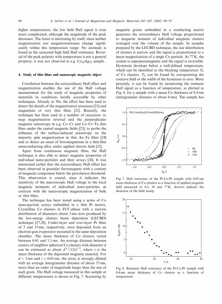
each grain. The Hall voltage measured in this sample at
different temperatures is shown in Fig. 7. Scattering by
magnetic grains embedded in a conducting matrix
generates the extraordinary Hall voltage proportional
to magnetic moment of individual magnetic clusters
averaged over the volume of the sample. In samples
prepared by the LECBD technique, the size distribution
of clusters is narrow and the signal is proportional to a
mean magnetization of a single Co particle. At 77K, the
system is superparamagnetic and the signal is reversible.
Hysteresis develops below a well-defined temperature,
which can be identified as the blocking temperature Tbof Co clusters. Tb can be found by extrapolating the
coercive field or the width of the hysteresis to zero. More
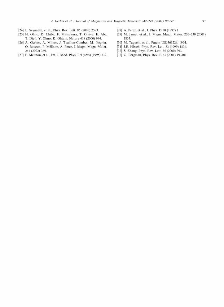
precisely, it can be found by monitoring the remnant
Hall signal as a function of temperature, as plotted in
Fig. 8, for a sample with a mean Co thickness of 0.4 nm
(intergranular distance of about 6 nm). The sample has
-1.0 -0.5 0.0 0.5 1.0
-1.0
-0.5
0.0
0.5
1.0 Pt(11nm)/Co(0.01nm)/Pt(5nm)
4K
10K
77K
RH
, a.
u.
B0,T
Fig. 7. Hall resistance of the Pt/Co/Pt sample with 0.01 nm
mean thickness of Co clusters as a function of applied magnetic
field measured at 4.2, 10 and 77K. Arrows indicate the
direction of the field sweep.
10 20 30 40
0
5
10
15
20
RH
(0),
mΩ
T, K
Fig. 8. Remnant Hall resistance of the Pt/Co/Pt sample with
0.4 nm mean thickness of Co clusters as a function of
temperature.
A. Gerber et al. / Journal of Magnetism and Magnetic Materials 242–245 (2002) 90–9794

been magnetized at 4.2K and slowly heated at zero
external field. The remnant Hall signal decreases
monotonically and approaches zero at about 25K,
which indicates the blocking temperature of Co clusters
in this sample. Determination of Tb in this experiment is
equivalent to the zero-field versus field-cooled magneti-
zation measurement. Magnetic anisotropy energy den-
sity C of a nano-particle can be calculated using e.g.
CVE25kBTb; where V is the particle volume, and kB is
the Boltzmann constant. For Tb ¼ 30K, we calculateCE7 106 erg/cm3 which is close to the value found in3D films [29]. The absolute value of the particle’s
magnetic moment can be found from the fit of the
measured Hall signal by the Langevin function at
temperatures above Tb; as shown in Fig. 9. Perfect fitof the 0.01 nm thick Co sample is found for
M ¼ 4:6 1017 erg/G, which corresponds to about
3 103 atoms of Co with a bulk value of atomic
magnetic moment (1.7 mB).The very use of the Hall resistivity for the study of
magnetic properties is attractive. Standard magneto-
metric techniques, like VSM, SQUID, Hall probe and
optical, detect magnetization of a sample by an external
measurement apparatus. In the present approach,
magnetization is revealed by an intrinsic transport
property of the material itself. The technique is
remarkable due to its simplicity; it is unlimited by field
and temperature constrains and is well adapted for the
study of ultrathin magnetic films and arrays of diluted
nano-particles.
5. Technical applications
So far, the extraordinary Hall effect has been almost
entirely ignored as a possible tool for technical applica-
tions in field sensors and memory devices. Time is
probably ripe to change this attitude. The basic
requirements for competitive magnetic field sensors
are: (a) high sensitivity; (b) linear field response; and
(3) absence of hysteresis in field dependence. Fig. 10
presents the Hall resistance of a 10 nm thick nickel film
(out of series (b), Fig. 3) as a function of an applied
magnetic field. One can mention at least three advan-
tages of this film as compared with bulk material and
thick films (see Fig. 1): (a) improved linearity of the Hall
signal versus magnetic field; (b) improved
sensitivityFdRH=dBE10O/T versus 2 102O/T in
130 nm thick film, and (c) hysteresis width less than
5G at room temperature. The magnitude of the
extraordinary Hall coefficient and, therefore, sensitivity
to magnetic field can be enhanced in a number of ways.
One of them is by decreasing the film thickness and
enhancing the surface scattering. A typical enhancement
of the field sensitivity in the low thickness limit of
chemically pure Ni films (series (a) Fig. 3) is shown in
Fig. 11. The data presented here are limited for uniform
continuous films and the thinnest sample shown is 7 nm
thick. Since the surface scattering resistivity diverges in
the zero-thickness limit, the sensitivity can be dramati-
cally increased in ultra-thin continuous films.
Combination of the Hall effect measurement techni-
que and use of films with perpendicular magnetic
anisotropy can be applied for memory devices [30].
The Hall resistance measured in a 6 nm thick Ni film is
plotted in Fig. 12. The signal is sharp with an almost
rectangular hysteresis. The difference between the up
and down magnetized states is about 2O, the width ofthe hysteresis is 300G and the magnetization reverse
slope is about 50O/T.Field sensitivity of the order of 10O/T in the simplest
Ni films justifies more work to be done. Materials with
0.0 0.2 0.4 0.6 0.8 1.0
0.0
0.2
0.4
0.6
0.8
1.0
Mfit=4.6×10⁻²⁰Am2
Pt(11nm)/Co(0.01nm)/Pt(5nm)
T=77 K
RH
, a.
u.
B0, T
Fig. 9. Measured Hall resistance of the Pt/Co/Pt sample with
0.01 nm mean thickness of Co clusters as a function of the
applied magnetic field at 77K (symbols). Solid line is the
Langevin function calculated with Mfit ¼ 4:6 1020 Am2.
-0.15 -0.10 -0.05 0.00 0.05 0.10 0.15
-0.50
-0.25
0.00
0.25
0.50 Ni 10nm
T=290 K
dRH 0/dB 10Ω/T
RH
, Ω
B0, T
∼∼
Fig. 10. Hall resistance of the 10 nm thick Ni film (out of series
(b), Fig. 4) as a function of applied field at 290K. Field
sensitivity is about 10O/T.
A. Gerber et al. / Journal of Magnetism and Magnetic Materials 242–245 (2002) 90–97 95

high extraordinary Hall response and low saturation
fields should be tried for the field sensing applications.
Films with perpendicular magnetic anisotropy should be
explored as the potential memory units.
6. Spin Hall effect
Finally, one should mention a particularly interesting
phenomenon closely related to the one discussed ear-
lierFspin Hall effect [31,32]. Asymmetric scattering of
spin-up versus spin-down electrons due to the spin–orbit
interaction, which is responsible for the anomalous Hall
effect, operates as a spin separation pump. This spin
Hall effect is predicted also in the cases with zero net
magnetization, e.g. in paramagnetic metals or doped
semiconductors. A variety of applications can be
anticipated. Use of the effect as an experimental tool
to measure spin current [33] is only one of them.
Acknowledgements
This research has been supported in part by AFIRST,
Franco–Israeli research program on nanotechnology,
grant No. 9841.
References
[1] E.M. Pugh, Phys. Rev. 36 (1930) 1503.
[2] C.M. Hurd, The Hall Effect in Metals and Alloys, Plenum
Press, New York, 1972.
[3] L. Berger, G. Bergmann, in: C.L. Chien, C.R. Westgate
(Eds.), The Hall Effect and its Applications, Plenum Press,
New York, 1980, p. 55 and references therein.
[4] A. Fert, A. Hamzi!c, in: C.L. Chien, C.R. Westgate (Eds.),
The Hall Effect and its Applications, Plenum Press, New
York, 1980, p. 77 and references therein.
[5] S.N. Song, C. Sellers, J.B. Ketterson, Appl. Phys. Lett. 59
(1991) 479.
[6] P. Xiong, G. Xiao, J.Q. Wang, J.Q. Xiao, J.S. Jiang,
C.L. Chien, Phys. Rev. Lett. 69 (1992) 3220.
[7] V. Korenivski, K.V. Rao, J. Colino, I.K. Schuller, Phys.
Rev. B 53 (1996) R11938.
[8] H. Sato, H. Henmi, Y. Kobayashi, Y. Aoki, H.
Yamamoto, T. Shinjo, V. Sechovsky, J. Appl. Phys. 76
(1994) 6919.
[9] J. Wang, G. Xiao, Phys. Rev. B 51 (1995) 5863.
[10] E.M. Kogan, V.V. Ustinov, Solid State Commun. 43
(1982) 743.
[11] J.M. Luttinger, Phys. Rev. 112 (1958) 739.
[12] S. Zhang, Phys. Rev. B 51 (1995) 3632.
[13] A. Crepieux, C. Lacroix, N. Ryzhanova, A. Vedyayev,
Phys. Lett. A 229 (1997) 401.
[14] N. Ryzhanova, A. Vedyayev, A. Crepieux, C. Lacroix,
Phys. Rev. B 57 (1998) 2943.
[15] A.V. Vedyaev, A.B. Granovskii, A.V. Kalitsov, F.
Brouers, JETP 85 (1997) 1204.
[16] E.H. Sondheimer, Adv. Phys. 1 (1952) 1.
[17] C.A. Neugebauer, Phys. Rev. 116 (1959) 1441.
[18] A.B. Pakhomov, X. Yan, B. Zhao, Appl. Phys. Lett. 67
(1995) 3497.
[19] B.A. Aronzon, D.Yu. Kovalev, A.N. Lagar’kov, E.Z.
Meilikhov, V.V. Ryl’kov, M.A. Sedova, N. Negre, M.
Gorian, J. Leotin, JETP Lett. 70 (1999) 90.
[20] J.C. Denardin, A.B. Pakhomov, M. Knobel, H. Liu,
X.X. Zhang, J. Phys.: Condens. Matter 12 (2000) 3397.
[21] S. Foner, Phys. Rev. 95 (1954) 652.
[22] R. Coren, H.J. Juretschke, J. Appl. Phys. 28 (1957) 806.
[23] S. Nakagawa, A. Sato, I. Sasaki, M. Naoe, J. Appl. Phys.
87 (2000) 5705.
0 20 40 60 80 100
0
1
2
3
4
5
Ni
T=290 K
dR
H/d
B0, Ω
/T
thickness, nm
Fig. 11. Field sensitivity of Ni films (series (a) Fig. 4) as a
function of their thickness.
-0.15 -0.10 -0.05 0.00 0.05 0.10 0.15
-1.0
-0.5
0.0
0.5
1.0
Ni, 6 nm, 4.2 K
RH
, Ω
B0, T
Fig. 12. Hall resistance of the 6 nm thick Ni film as a function
of applied field at 4.2KFprototype of the memory unit.
A. Gerber et al. / Journal of Magnetism and Magnetic Materials 242–245 (2002) 90–9796
[24] E. Seynaeve, et al., Phys. Rev. Lett. 85 (2000) 2593.
[25] H. Ohno, D. Chiba, F. Matsukura, T. Omiya, E. Abe,
T. Dietl, Y. Ohno, K. Ohtani, Nature 408 (2000) 944.
[26] A. Gerber, A. Milner, J. Tuaillon-Combes, M. N!egrier,
O. Boisron, P. M!elinon, A. Perez, J. Magn. Magn. Mater.
241 (2002) 369.
[27] P. M!elinon, et al., Int. J. Mod. Phys. B 9 (4&5) (1995) 339.
[28] A. Perez, et al., J. Phys. D 30 (1997) 1.
[29] M. Jamet, et al., J. Magn. Magn. Mater. 226–230 (2001)
1833.
[30] M. Taguchi, et al., Patent US5361226, 1994.
[31] J.E. Hirsch, Phys. Rev. Lett. 83 (1999) 1834.
[32] S. Zhang, Phys. Rev. Lett. 85 (2000) 393.
[33] G. Bergman, Phys. Rev. B 63 (2001) 193101.
A. Gerber et al. / Journal of Magnetism and Magnetic Materials 242–245 (2002) 90–97 97