extra class exam study guide march 2013 - k4vrc€¦ · extra class exam study guide march 2013...
TRANSCRIPT

Extra Class Exam Study Guide March 2013
Page 1

Extra Class Exam Study Guide March 2013
Page 2
Introduction
Amateur radio has been around for a long time and has grown itself into a worldwide community of
licensed hams on the airwaves with all sorts of communications technology. Ham radio attracts
those who have never held a microphone as well as deep technical experts who grew up with a
soldering iron and computer. Your United States Amateur Service license gives you the most
powerful wireless communications capability available to any private citizen anywhere in the world.
In the United States, amateur radio licensing is governed by the Federal Communications
Commission (FCC) under strict federal regulations. Licenses to operate amateur stations for
personal use are granted to individuals of any age once they demonstrate an understanding of both
pertinent FCC regulations and knowledge of radio station operation and safety considerations.
December 2012 marked one hundred years of amateur radio operator and station licensing by the
United States government. Operator licenses are divided into different classes, each of which
correlates to an increasing degree of knowledge and corresponding privileges. Over the years, the
details of the classes have changed significantly, leading to the current system of three open
classes and two grandfathered but closed to new applicants. The top US license class is Amateur
Extra Class. The Extra Class license requires an applicant pass 35 of a 50 question multiple-choice
theory exam. Those with Amateur Extra licenses are granted all privileges on all US amateur
bands.
The ARRL Extra Class License description says it best; “General licensees may upgrade to Extra
Class by passing a 50-question multiple-choice examination. No Morse code test is required.
In addition to some of the more obscure regulations, the test covers specialized operating
practices, advanced electronics theory and radio equipment design. Non-licensed individuals
must pass Element 2, Element 3 and Element 4 written exams to earn an Extra License. The
FCC grants exam element 3 credit to individuals that previously held certain older types of
licenses. The HF bands can be awfully crowded, particularly at the top of the solar cycle.
Once one earns HF privileges, one may quickly yearn for more room. The Extra Class license is
the answer. Extra Class licensees are authorized to operate on all frequencies allocated to
the Amateur Service.”
The Extra Class workshop must cover a vast amount of material in six classes. This workshop will
be conducted as peers sitting around a table discussing a technical topic. This is the format
requested as specific technical topics not a rote review of the questions. The material in this study
guide is formatted as abbreviated points or a quick reference format instead of slides. It is intended
that the guide combined with the reference material supplied will have long-term value.
The workshop is specially presented for those with amateur radio experience who want to learn
more. The workshop will primarily focus on technical aspects of the exam and regulatory questions
are expected to be self-study. This is intended to help members advance in the hobby we love and
give a little boost to those on the fence.
Looking forward to congratulating you in your advancement to Amateur Extra Class,
Rick
WD4JJI Richard Silverston
President
The Villages Amateur Radio Club

Extra Class Exam Study Guide March 2013
Page 3
How to best use this guide
This study guide is written to help you understand the radio theory with a practical slant, not just teach the answers, although the scope is limited to question pool topics due to the limited workshop time. This guide presents and explains the Extra Class License Exam questions by discussing each sub-group as an individual topic. There are fifty-four topics in this guide which represent approximately one for each of the fifty exam questions. This study guide is not intended to circumvent reading the assigned ARRL textbook chapter(s) but to support a better understanding of the radio theory. Start by reading the next few pages to be sure you have all your supplies and look at the summary of the math required during the exam. This will give you time to order material without the last minute rush. Everything is provided as a PDF format for your use. Determine how you want to read your personal copy of this guide and supporting material. In today’s world an electronic reader may be the right choice or if you prefer paper you can print out the workshop material and place it in a three-ring binder. Do not wait until the weekend prior to the workshop to prepare. Read the ARRL textbook completely before the workshops. You will not understand everything but it will help put everything into perspective during the workshops. Take online practice tests prior to the workshops but don’t worry about the score yet.
Online Practice Tests
http://aa9pw.com/radio/ www.eham.net/exams http://kb0mga.net/exams/ www.radioexam.org
A few days before each workshop read the ARRL textbook chapter(s) assigned and work the problems. It is a good idea to work your problems in a notebook and bring it to class for your reference and help finding where that decimal point got lost. Review the exam question group(s) assigned in this study guide to help focus on the key takeaways and scribble down questions to ask during the workshop. Again, take the online practice tests and review the questions you failed in your ARRL textbook and this guide. If you are still having trouble, review the technical references on the workshop CD ROM. These documents have much more detail and are explained in different ways from the book. You will find over a hundred technical references on the workshop CD ROM and you are not expected to have time to read all of them. The references are arranged by Question Pool Group Number; E0, E1, E2… E9 followed by a subject title and number (i.e.1,2,3). Start with title #1 and progress to the higher numbers as they increase in detail. If you have questions about decibels or just want more information read “E9-dB-1” before “E9-dB-2”. If you still are having difficulties with a question(s), the workshop discussion should clarify the problem. Do NOT be self-conscious if you are having trouble understanding; it is very likely the rest of the workshop is also not sure. This will be a discussion group format so every workshop is intended to address your questions even if they are not part of assignment, just be considerate of the workshop’s limited time. The last workshop will be devoted to topic(s) as requested.

Extra Class Exam Study Guide March 2013
Page 4
Supplies you will need
ARRL Tenth Edition of the Extra Class License Manual
ARRL Extra Class License Manual 10th Edition ISBN: 978-0-87259-517-0 for use July 1, 2012 to June 30, 2016 Available from ARRL, book stores or ham radio retailers
Pencil/pen and note pad to take notes and work out problems The workshop CD-ROM You will need access to a home computer to read the documents on the workshop CD-ROM and to take practice exams. Scientific Calculator with the following functions;
Add
Subtract
Divide
Multiple
Squares
Square Roots
Sine
Cosine
Arctan or tan-1 (Inverse Tangent)
Base Ten Logarithms (10^x) The formal test will require you to clear your memory so purchase a calculator with little or no memory. You want to use the same calculator during home study, practice tests, workshop exercises and the real test. Many points are lost to math errors so you want a calculator that you can operate with confidence.

Extra Class Exam Study Guide March 2013
Page 5
Math you will need to use
Calculations Add, Subtract, Divide & Multiple Squares & Square Roots Sine & Cosine Arctan or tan-1 (Inverse Tangent) Base Ten Logarithms (10^x) The workshop and license exam requires you to use a small amount of algebra and trigonometry to solve problems. Every equation you need to use is listed below. Working solving the example problems will help you be at ease with using the math. If you would like to learn a bit about trigonometry, or brush up on it, then you can but do not lose focus on the radio theory. These equations are more of an introduction and guide and the actual exam question calculations will be shown step by step during the workshop. For more help you should read the math reference material on your CD-ROM.
Conversions dB to ratio >> ratio = 10 ^ (dB/10) > Solve for 5.2 dB > ? = 10 ^ (5.2dB / 10) = 10 ^ 0.52 = 3.311
0dB = 1 3 dB = 1.995 6 dB = 3.981 9dB = 7.943 12dB = 15.849 ratio to dB >> dB = 10 x log ( ratio/10 ) > Solve for 800 > ? = 10 x log (800) = 10 X 2.9031= 29.031dB
2 = 3dB 75 = 18.75dB 500 = 26.99dB 1500 = 31.76dB
Inductor Impedance >> Ω = 2 π FL = 2 x π x MHz x uH
Solve for 18 uH @ 3.505 MHz > ? = 3.505 x 18 = 396.41 Ω Capacitor Impedance >> Ω = 1/ (2 π FC) = 1/ (2 x π x MHz x uF) Solve for 38 pF @ 14 MHz >
? = 1 / (2 x 3.14 x 14 x 0.000038) = 1 / 0.00334096 = 299.32 Ω
Series RLC Impedance >> Freq = 1/[2π√(LC)] Note the R drops out!
Solve for 40 pF + 50 uH + 22 Ω >
? = 1/[6.28x√(0.00005x0.00000000004)] = 1/(2.808501379739736e-7) = 3560618 Hz = 3.56 MHz Parallel RLC Impedance >> Freq = 1/[2π√(LC)] Note the R drops out and use same equation for resonance!
Solve for 10 pF + 25 uH + 47 Ω >
? = 1/[6.28x√(0.000025x0.00000000001)] = 1/(9.929551852911e-8) = 10.070948 MHz
RC Time Constant >> TC (sec) = R (MΩ) x C (uF) Solve for 440 pF + 500K Ω > ? = 0.5 x 440 = 220 Seconds
Polar to Rectangular Coordinates >> Magnitude at an angle or a vector >> X = M x Cos ϑ and Y = M x Sin ϑ Solve for 200 at 30° > X = 200 x Cos 30° = 173.20 Y = 200 x Sin 30° = 100
Rectangular to Polar Coordinates >> Magnitude = √[X2 + Y
2] and the angle = tan^-1 [Y / X]
Solve for X = 400 and Y = 300
M = √[4002 +
3002] = √ 250,000 = 500
ϑ = tan^-1 [300/400] = tan^-1 (0.75) = 36.87°

Extra Class Exam Study Guide March 2013
Page 6
TVARC 2013 Workshop Meeting Schedule
Class Date ARRL Chap
Question Pool Group rev Dec 18, 2012
E1 COMMISSION’S RULES
Self Study 3 E1A Operating Standards
Self Study 3 E1B Station restrictions & special operations
Self Study 3 E1C Station control
Self Study 3 E1D Amateur Satellite service
Self Study 3 E1E Volunteer examiner program
Self Study 3 E1F Misc
E5 ELECTRICAL PRINCIPLES
Mon 3/4 4 E5A Resonance & Q: resonant circuits
Mon 3/4 4 E5B Time constants & phase relationships
Mon 3/4 4 E5C Impedance plots & coordinate systems
Mon 3/4 4 E5D AC & RF in real circuits
E6 CIRCUIT COMPONENTS
Wed 3/6 5 E6A Semiconductors
Wed 3/6 5 E6B Semiconductor diodes
Wed 3/6 5 E6C Integrated circuits
Wed 3/6 4,5 E6D Optical & Toroids
Wed 3/6 5,6 E6E Piezoelectric crystals & MMICs
Wed 3/6 5 E6F Optical
E7 PRACTICAL CIRCUITS
Mon 3/11 5 E7A Digital circuits
Mon 3/11 6 E7B Amplifiers Classes
Mon 3/11 6 E7C Filters & impedance matching networks
Mon 3/11 6 E7D Power supplies & voltage regulators
Mon 3/11 6 E7E Modulation & demodulation
Mon 3/11 5 E7F Frequency markers & counters
Mon 3/11 6 E7G Active filters & op-amps
Mon 3/11 6 E7H Oscillators & signal sources
E8 SIGNALS & EMISSIONS
Wed 3/13 7,8 E8A AC waveforms
Wed 3/13 7 E8B Modulation & demodulation methods
Wed 3/13 8 E8C Digital signals: digital modes
Wed 3/13 7 E8D Waves, measurements, RF grounding

Extra Class Exam Study Guide March 2013
Page 7
TVARC 2013 Workshop Meeting Schedule
Class Date ARRL Chap
Question Pool Group rev Dec 18, 2012
E2 OPERATING PROCEDURES
Wed 3/13 2 E2A Amateur radio in space
Wed 3/13 8 E2B Television practices
Wed 3/13 2 E2C DX; spread-spectrum; Operating Frequency
Wed 3/13 2 & 8 E2D VHF and UHF digital modes; APRS
Wed 3/13 8 E2E HF digital modes
E4 AMATEUR PRACTICES
Mon 3/18 7,8,9 E4A Test equipment
Mon 3/18 7&9 E4B Measurement limitations
Mon 3/18 8 E4C Phase noise, image rejection, S/N
Mon 3/18 7&8 E4D Dynamic range, IMD, 3rd order intercept
Mon 3/18 7 E4E Noise suppression
E9 ANTENNAS & TRANSMISSION LINES
Wed 3/20 9 E9A Isotropic & gain antennas
Wed 3/20 9 E9B Antenna patterns
Wed 3/20 9 E9C Wire & phased antennas
Wed 3/20 9 E9D Directional antennas
Wed 3/20 9 E9E Matching
Wed 3/20 9 E9F Transmission lines
Wed 3/20 9 E9G Smith Charts
Wed 3/20 9 E9H Effective radiated power
Wed 3/20 9 E9H Radio Direction Finding Antennas
E3 RADIO WAVE PROPAGATION
Self Study 10 E3A Earth-Moon-Earth, meteor scatter
Self Study 10 E3B Long path; gray-line; multi-path propagation
Self Study 10 E3C Aurora, fading; radio horizon; take-off angle
E0 SAFETY
Self Study 11 E0A Amateur radio safety practices
Mon 3/25 Topic(s) determined by class requests
Wed 3/27 VEC Testing all Levels

Extra Class Exam Study Guide March 2013
Page 8
Table of Contents
INTRODUCTION ............................................................................................................................................. 2 HOW TO BEST USE THIS GUIDE ..................................................................................................................... 3 SUPPLIES YOU WILL NEED ............................................................................................................................. 4 MATH YOU WILL NEED TO USE ..................................................................................................................... 5 TVARC 2013 WORKSHOP MEETING SCHEDULE ............................................................................................ 6
SUBELEMENT E0 – SAFETY - [1 exam question -– 1 group] E0A Safety: amateur radio safety practices; RF radiation hazards; hazardous materials .......................... 10
SUBELEMENT E1 - COMMISSION’S RULES [6 Exam Questions - 6 Groups] E1A Operating Standards ............................................................................................................................ 15 E1B Station restrictions and special operations ......................................................................................... 17 E1C Station control ..................................................................................................................................... 21 E1D Amateur Satellite service ..................................................................................................................... 22 E1E Volunteer examiner program............................................................................................................... 24 E1F Miscellaneous rules .............................................................................................................................. 25
SUBELEMENT E2 - OPERATING PROCEDURES [5 Exam Questions - 5 Groups] E2A Amateur radio in space ........................................................................................................................ 27 E2B Television practices .............................................................................................................................. 29 E2C Contest and DX operating; spread-spectrum transmissions; selecting an operating frequency ........ 31 E2D Operating methods: VHF and UHF digital modes; APRS ..................................................................... 32 E2E Operating methods: operating HF digital modes; error correction ..................................................... 33
SUBELEMENT E3 - RADIO WAVE PROPAGATION [3 Exam Questions - 3 Groups] E3A Propagation and technique, Earth-Moon-Earth communications; meteor scatter ............................ 34 E3B Propagation and technique, trans-equatorial; long path; gray-line; multi-path propagation ............ 35 E3C Propagation and technique, Aurora propagation; selective fading; radio-path horizon; take-off ...... 37
SUBELEMENT E4 - AMATEUR PRACTICES [5 Exam Questions - 5 Groups] E4A Test equipment: analog & digital instruments; spectrum,network analyzers, antenna analyzers ..... 39 E4B Measurement technique and limitations: instrument accuracy and performance limitations .......... 41 E4C Receiver, phase noise, capture effect, noise floor, image rejection, MDS .......................................... 43 E4D Receiver, blocking dynamic range, intermodulation and cross-modulation; 3rd order intercept ...... 46 E4E Noise suppression: system noise; electrical appliance noise; line noise; locating noise sources ....... 48
SUBELEMENT E5 - ELECTRICAL PRINCIPLES [4 Exam Questions - 4 Groups] E5A Resonance and Q: characteristics of resonant circuits: series and parallel resonance ....................... 49 E5B Time constants and phase relationships: RLC time constants: definition ........................................... 51 E5C Impedance plots and coordinate systems: polar coordinates; rectangular coordinates .................... 53 E5D AC and RF energy in real circuits: skin effect; electrostatic and electromagnetic fields ..................... 57
SUBELEMENT E6 - CIRCUIT COMPONENTS [6 Exam Questions - 6 Groups] E6A Semiconductor materials and devices: germanium, silicon: NPN, PNP, field-effect transistors ......... 59 E6B Semiconductor diodes ......................................................................................................................... 61 E6C Integrated circuits: TTL digital integrated circuits; CMOS digital integrated circuits; gates................ 63 E6D Optical devices and toroids: cathode-ray tube devices; CCDs; LCDs; toroids: permeability .............. 64 E6E Piezoelectric crystals and MMICs: crystals; crystal oscillators & filters; monolithic amplifiers ........... 66 E6F Optical components and power systems: photovoltaic, optical couplers, sensors, optoisolators...... 68

Extra Class Exam Study Guide March 2013
Page 9
Table of Contents
SUBELEMENT E7 - PRACTICAL CIRCUITS [8 Exam Questions - 8 Groups] E7A Digital circuits: classes of logic elements; negative logic; frequency dividers; truth tables ................ 69 E7B Amplifiers: Class; tubes; distortion, intermodulation; spurious, parasitic; microwave amplifiers ...... 71 E7C Filters and matching networks; filter applications; impedance matching; DSP filtering ..................... 73 E7D Power supplies and voltage regulators ............................................................................................... 75 E7E Modulation and demodulation: reactance, phase and balanced; detectors; mixer; DSP , SDR .......... 77 E7F Frequency markers and counters: divider circuits; generators; frequency counters .......................... 79 E7G Active filters and op-amps: active audio filters; basic circuit design; operational amplifiers ............. 80 E7H Oscillators and signal sources: oscillators; phase-locked loops; direct digital synthesizers ............... 82
SUBELEMENT E8 - SIGNALS AND EMISSIONS [4 Exam Questions - 4 Groups] E8A AC waveforms: sine, square, sawtooth and irregular waveforms ....................................................... 84 E8B Modulation methods; modulation index and deviation ratio; pulse modulation; FDMA,TDMA ........ 86 E8C Digital signals: digital communications modes; CW; data rate vs. bandwidth; spread-spectrum ...... 88 E8D Waves, measurements, and RF grounding: peak-to-peak values, polarization; RF grounding ........... 90
SUBELEMENT E9 - ANTENNAS AND TRANSMISSION LINES [8 Exam Questions - 8 Groups] E9A Isotropic and gain antennas; radiation pattern; resistance and reactance, gain, BW, efficiency ....... 92 E9B Antenna patterns: E and H plane patterns; gain as a function of pattern; Yagi antennas .................. 94 E9C Wire and phased vertical antennas: beverage; rhombic antennas; ground ....................................... 95 E9D Directional antennas: gain; satellite antennas; beamwidth; SWR bandwidth; efficiency .................. 97 E9E Matching: matching antennas to feed lines; power dividers .............................................................. 99 E9F Transmission lines: open and shorted feed lines: coax versus open-wire; velocity factor ............... 101 E9G Smith chart ........................................................................................................................................ 102 E9H Effective radiated power; system gains and losses; radio direction finding antennas ..................... 104
INDEX ........................................................................................................................................................ 107

Extra Class Exam Study Guide March 2013
Page 10
E0A Safety
Chapters 11 of ARRL Extra Class License Manual Estimated 1 Exam Question
Radioactive materials emit ionizing radiation, while RF signals have less energy and can only cause heating
RF exposure levels at your station at a neighbor’s home must be less than the uncontrolled MPE limits
Using an antenna modeling program to calculate field strength is a practical way to estimate whether the RF fields produced by an amateur radio station are within permissible MPE limits

Extra Class Exam Study Guide March 2013
Page 11
Every transmitter that produces 5% or more of its MPE exposure limit at accessible locations for multiple transmitters operating at the same time each of the operators and licensees of which transmitters are responsible for mitigating over-exposure situations
Localized heating of the body from RF exposure in excess of the MPE limits result from using high-power UHF or microwave transmitters
Editor’s note: The body heating from RF exposure is analysis below is included to show how the body surface is heated by RF. This means the primary RF hazard in your shack is your skin and eyes.
The National Institute of Information and Communications Technology (NICT) disclosed a numerical model database of a whole-body Japanese pregnant woman. The database was jointly developed with Chiba University. Numerical Model Data of Pregnant Woman Disclosed for Electromagnetic Field Analysis The distribution of the Specific Absorption Rate (SAR) per unit mass, at the time of frontal exposure to radio waves. Frequencies: 80MHz and 2GHz. Strength: 1mW/cm2), is shown by color.
SAR is the rate at which RF energy is absorbed by the body
The high gain antennas commonly used can result in high RF exposure levels using microwaves in the amateur radio bands
Why are there separate electric (E) and magnetic (H) field MPE limits? A. The body reacts to electromagnetic radiation from both the E and H fields B. Ground reflections and scattering make the field impedance vary with location C. E field and H field radiation intensity peaks can occur at different locations D. All of these choices are correct
Dangerous levels of carbon monoxide from an emergency generator can be detected with a carbon monoxide detector
Beryllium Oxide commonly used as a thermal conductor for some types of electronic devices is extremely toxic if broken or crushed and the particles are accidentally inhaled
Polychlorinated biphenyls found in some electronic components such as high-voltage capacitors and transformers is considered toxic

Extra Class Exam Study Guide March 2013
Page 12
Remember this question from the General License Exam?
G0A03 | (D) How can you determine that your station complies with FCC RF exposure regulations? A. By calculation based on FCC OET Bulletin 65 B. By calculation based on computer modeling C. By measurement of field strength using calibrated equipment D. All of these choices are correct
You will NOT see this on the Extra exam but you should have analysis on file like the one below!

Extra Class Exam Study Guide March 2013
Page 13

Extra Class Exam Study Guide March 2013
Page 14

Extra Class Exam Study Guide March 2013
Page 15
E1A Operating Standards
Chapters 3 of ARRL Extra Class License Manual Estimated 1 Exam Question
Upper Sideband (USB) emissions will be 3 kHz above the carrier frequency
Lower Sideband (LSB) emissions will be 3 kHz below the carrier frequency
With your transceiver displaying the carrier frequency of phone signals, you hear a DX station's CQ on 14.349 MHz USB it is NOT legal to return the call using upper sideband on the same frequency
With your transceiver displaying the carrier frequency of phone signals, you hear a DX station calling CQ on 3.601 MHz LSB it is NOT legal to return the call using lower sideband on the same frequency
With your transceiver displaying the carrier frequency of CW signals, you hear a DX station's CQ on 3.500 MHz it is NOT legal to return the call using CW on the same frequency
100 watts PEP effective radiated power relative to the gain of a half-wave dipole is the maximum power output permitted on the 60 meter band
Operation is restricted to specific emission types and specific channels describes the rules for operation on the 60 meter band
60 meter band is the only amateur band where transmission on specific channels rather than a range of frequencies is permitted

Extra Class Exam Study Guide March 2013
Page 16
If a station in a message forwarding system inadvertently forwards a message that is in violation of FCC rules, the control operator of the originating station is primarily accountable for the rules violation
The first action you should take if your digital message forwarding station inadvertently forwards a communication that violates FCC rules is to discontinue forwarding the communication as soon as you become aware of it
Operation of an amateur station is installed aboard a ship or aircraft must be approved by the master of the ship or the pilot in command of the aircraft
A FCC-issued amateur license or a reciprocal permit for an alien amateur licensee is required when operating an amateur station aboard a US-registered vessel in international waters
A FCC-issued amateur license or a reciprocal permit for an alien amateur licensee is required when operating an amateur station aboard any vessel or craft that is documented or registered in the United States

Extra Class Exam Study Guide March 2013
Page 17
E1B Station restrictions & Special operations
Chapters 3 of ARRL Extra Class License Manual Estimated 1 Exam Question
An emission outside its necessary bandwidth that can be reduced or eliminated without affecting the information transmitted constitutes a spurious emission
The mean power of any spurious emission must be at least - 43 dB relative to the mean power of the fundamental emission from a station transmitter or external RF amplifier installed after January 1, 2003, and transmitting on a frequency below 30 MHZ
1.0 is the highest modulation index permitted at the highest modulation frequency for angle modulation

Extra Class Exam Study Guide March 2013
Page 18
Operating with a 2.5kHz filter, an Upper Sideband transmitter set at 1.5kHz below the center-of-channel frequency, with a typical voice bandpass of 300Hz to 2800Hz, the signal will just barely meet the requirements of the FCC rules for the 2.8kHz channel.
2.8 kHz is the maximum bandwidth for a data emission on 60 meters
The carrier frequency of a CW signal must be at the center frequency of the channel to comply with FCC rules for 60 meter operation
Locations of environmental importance or significant in American history, architecture, or culture might cause the physical location of an amateur station apparatus or antenna structure to be restricted
An Environmental Assessment must be submitted to the FCC before placing an amateur station within an officially designated wilderness area or wildlife preserve, or an area listed in the National Register of Historical Places
The 60 Met er BandOpened t o gener al and above on Jul y 1, 2003
5,332 KHZ 5,348 KHZ 5,368 KHZ 5,405 KHZ5,373 KHZ
• On assigned frequencies (channels) only
• Maximum 2.8 KHz occupied bandwidth (± 1.4 KHz from channel freq.)
•Therefore must tune 1.4 KHz lower than channel frequency
• (USB) Upper Side Band Only
• Max ERP (Effective Radiated Power of 50 Watts referenced to a dipole
Tune to 5,330.5 KHZ
Tune to 5,371.5 KHZ
Tune to 5,36.5 KHZ Tune to 5,403.5 KHZ
Tune to 5,345.5 KHZ

Extra Class Exam Study Guide March 2013
Page 19
If you are installing an amateur station antenna at a site at or near a public use airport you may have to notify the Federal Aviation Administration and register it with the FCC as required by Part 17 of FCC rules
FCC monitoring facility must protect that facility from harmful interference. Failure to do so could result in imposition of operating restrictions upon the amateur station by an EIC pursuant to Sec. 97.121 of this part. Geographical coordinates of the facilities that require protection are listed in Sec. 0.121 (c) of this chapter. There are 14 such stations listed in 47 CFR 0.121(b) and are shown below.
Within 1 mile an amateur station must protect an FCC monitoring facility from harmful interference

Extra Class Exam Study Guide March 2013
Page 20
Any FCC-licensed amateur station certified by the responsible civil defense organization for the area served may be operated in RACES
All amateur service frequencies authorized to the control operator are authorized to an amateur station participating in RACES
An amateur station could be required to avoid transmitting during certain hours on frequencies that cause the interference if its signal causes interference to domestic broadcast reception, assuming that the receiver(s) involved are of good engineering design

Extra Class Exam Study Guide March 2013
Page 21
E1C Station Control
Chapters 3 of ARRL Extra Class License Manual Estimated 1 Exam Question
The use of devices and procedures for control so that the control operator does not have to be present at a control point is automatic control of a station
Under automatic control the control operator is not required to be present at the control point
An automatically controlled station may retransmit third party communications when transmitting RTTY or data emissions
An automatically controlled station may NOT originate third party communications
29.500 - 29.700 MHz are available for an automatically controlled repeater operation
Only auxiliary, repeater or space stations may automatically retransmit the radio signals of other amateur stations
A control operator must be present at the control point of a remotely controlled amateur station
A station controlled indirectly through a control link is a remotely controlled station
3 minutes is the maximum permissible duration of a remotely controlled station’s transmissions if its control link malfunctions
Direct manipulation of the transmitter by a control operator is meant by local control

Extra Class Exam Study Guide March 2013
Page 22
E1D Amateur Satellite Service
Chapters 3 of ARRL Extra Class License Manual Estimated 1 Exam Question
The amateur satellite service is a radio communications using amateur radio stations on satellites
A telecommand station is an amateur station that transmits communications to initiate, modify or terminate functions of a space station
A telecommand station is designated by the space station licensee, subject to the privileges of the class of operator license held by the control operator
A space station must terminate transmissions by telecommand when directed by the FCC
Telemetry is one-way transmission of measurements at a distance from the measuring instrument

Extra Class Exam Study Guide March 2013
Page 23
40m, 20m, 17m, 15m, 12m and 10m bands have HF frequencies authorized to space stations
2M, 70 cm, 23 cm, 13 cm bands have frequencies authorized to space stations
An Earth station is an amateur station within 50 km of the Earth's surface intended for communications with amateur stations by means of objects in space
An Earth station is any amateur station, subject to the privileges of the class of operator license held by the control operator
All classes of licensee is authorized to be the control operator of a space station

Extra Class Exam Study Guide March 2013
Page 24
E1E Volunteer Examiner Program
Chapters 3 of ARRL Extra Class License Manual Estimated 1 Exam Question
A Volunteer Examiner Coordinator (VEC) is an organization that has entered into an agreement with the FCC to coordinate amateur operator license examinations
The Volunteer Examiner (VE) accreditation process is the procedure by which a VEC confirms that the VE applicant meets FCC requirements to serve as an examiner
Three is the minimum number of qualified VEs required to administer an Element 4 amateur operator license examination
Three VEs must certify that the examinee is qualified for the license grant and that they have complied with the administering VE requirements
The questions for all written US amateur license examinations are listed in a question pool maintained by all the VECs
A score of 74% is the minimum passing score on amateur operator license examinations
Each administering VE is responsible for the proper conduct and necessary supervision during an amateur operator license examination session
Immediately terminate the candidate’s examination if a candidate fails to comply with the examiner’s instructions during an amateur operator license examination
A VE not administer an examination to relatives of the VE as listed in the FCC rules
The penalty for a VE who fraudulently administers or certifies an examination is revocation of the VE’s amateur station license grant and the suspension of the VE’s amateur operator license grant
The administering VEs must submit the application document to the coordinating VEC according to the coordinating VEC instructions after the administration of a successful examination for an amateur operator license
The VE team must return the application document to the examinee with the application form if the examinee does not pass the exam
Preparing, processing, administering and coordinating an examination for an amateur radio license are out-of-pocket expenses that may be reimbursed VEs and VECs
The licensee's license will be cancelled for failing to appear for re-administration of an examination when so directed by the FCC

Extra Class Exam Study Guide March 2013
Page 25
E1F Miscellaneous Rules
Chapters 3 of ARRL Extra Class License Manual Estimated 1 Exam Question
LINE A is an area roughly parallel to and about 75 miles south of the US-Canadian border
Amateur stations may not transmit on 420 - 430 MHz if they are located in the contiguous 48 states and north of Line A
The National Radio Astronomy Observatory sites are located in Green Bank West Virginia, Socorro New Mexico, and Charlottesville NC.
The National Radio Quiet Zone is an area surrounding the National Radio Astronomy Observatory
Spread spectrum transmissions permitted on amateur frequencies above 222 MHz
10 W is the maximum transmitter power for an amateur station transmitting spread spectrum
Which of the following conditions apply when transmitting spread spectrum emission? A. A station transmitting SS emission must not cause harmful interference to other stations employing other authorized emissions B. The transmitting station must be in an area regulated by the FCC or in a country that permits SS emissions C. The transmission must not be used to obscure the meaning of any communication D. All of these choices are correct

Extra Class Exam Study Guide March 2013
Page 26
An external RF power amplifier if it is to qualify for a grant of FCC certification must satisfy the FCC's spurious emission standards when operated at the lesser of 1500 watts, or its full output power
A dealer sell an external RF power amplifier capable of operation below 144 MHz if it has not been granted FCC certification if it was purchased in used condition from an amateur operator and is sold to another amateur operator for use at that operator's station
Communications transmitted for hire or material compensation, except as otherwise provided in the rules are prohibited
Communications incidental to the purpose of the amateur service and remarks of a personal nature may be transmitted to amateur stations in foreign countries
CEPT agreement allows an FCC-licensed US citizen to operate in many European countries, and alien amateurs from many European countries to operate in the US
The FCC may issue a "Special Temporary Authority" (STA) to an amateur station to provide for experimental amateur communications
Only Technician, General, Advanced or Amateur Extra Class operators may be the control operator of an auxiliary station (no Novice!)
An amateur station may send a message to a business when neither the amateur nor his or her employer has a pecuniary interest in the communications

Extra Class Exam Study Guide March 2013
Page 27
E2A Amateur Radio in Space
Chapters 2 of ARRL Extra Class License Manual Estimated 1 Exam Question
A Geostationary satellite appears to stay in one position in the sky
The orbital period is the time it takes for a satellite to complete one revolution around the Earth
Calculations using Keplerian Elements for a satellite is one way to predict the location of a satellite
From south to north is the direction of an ascending pass for an amateur satellite
From north to south is the direction of a descending pass for an amateur satellite?

Extra Class Exam Study Guide March 2013
Page 28
The term mode (as applied to an amateur radio satellite) is the uplink and downlink frequency bands
The letters in a satellite's mode designator specify the uplink and downlink frequency ranges
A circularly polarized antenna can be used to minimize the effects of spin modulation and Faraday rotation
If the signal from an amateur satellite exhibit a rapidly repeating fading effect means the satellite is spinning
Limit YOUR power to a satellite which uses a linear transponder to avoid reducing the downlink power to others
In a linear transponder the largest received signal sets the transponder output power. Signals less than the larger signal are attenuated and therefore are re-sent at a lower power than the larger signal. Using the minimum power needed to access the transponder will allow more users to have access to the transponder. – AD7FO Which of the following types of signals can be relayed through a linear transponder?
A. FM and CW B. SSB and SSTV C. PSK and Packet D. All of these choices are correct

Extra Class Exam Study Guide March 2013
Page 29
E2B Television Practices
Chapters 8 of ARRL Extra Class License Manual Estimated 1 Exam Question
NTSC is the video standard used by North American Fast Scan ATV stations
30 frames per second are transmitted in a fast-scan (NTSC) television system
525 horizontal lines make up a fast-scan (NTSC) television frame
An interlaced scanning pattern generated by scanning odd numbered lines in one field and even numbered ones in the next in a fast-scan (NTSC) television system
Blanking in a video signal is turning off the scanning beam while it is traveling from right to left or from bottom to top
Chroma is the name of the signal component that carries color information in NTSC video
Vestigial sideband reduces bandwidth while allowing for simple video detector circuitry for standard fast- scan TV transmissions
Vestigial sideband is amplitude modulation in which one complete sideband and a portion of the other are transmitted
1255 MHz is one likely to find FM ATV transmissions
Which of the following is a common method of transmitting accompanying audio with amateur fast-scan television?
A. Frequency-modulated sub-carrier B. A separate VHF or UHF audio link C. Frequency modulation of the video carrier D. All of these choices are correct

Extra Class Exam Study Guide March 2013
Page 30
Digital Radio Mondiale (DRM) can be decoded using a receiver with SSB capability and a suitable computer
Digital Radio Mondiale (DRM) based voice or SSTV digital transmissions made on the HF amateur bands has a 3 KHz bandwidth
3 kHz is the approximate bandwidth of a slow-scan TV signal
Slow scan TV transmissions are restricted to phone band segments and their bandwidth can be no greater than that of a voice signal of the same modulation type
Analog SSTV images typically transmitted on the HF bands by varying tone frequencies representing the video are transmitted using single sideband
Tone frequency of an amateur slow-scan television signal encodes the brightness of the picture
128 or 256 lines are commonly used in each frame on an amateur slow-scan color television picture
Specific tone frequencies signal SSTV receiving equipment to begin a new picture line
The Vertical Interval Signaling (VIS) code transmitted as part of an SSTV transmission identifies the SSTV Mode

Extra Class Exam Study Guide March 2013
Page 31
E2C Operating Frequency & DX
Chapters 2 of ARRL Extra Class License Manual Estimated 1 Exam Question
Operators are permitted to make contacts even if they do not submit a log during contest operation
“self-spotting” is the prohibited practice of posting one’s own call sign and frequency on a call sign spotting network
146.52 MHz is a frequency that contest contact generally discouraged
30 meters bands is amateur radio contesting generally excluded
During a VHF/UHF contest the weak signal segment of the band, with most of the activity near the calling frequency would have the highest level of activity
Send your full call sign once or twice when attempting to contact a DX station working a pileup or in a contest
Switching to a lower frequency HF band might help to restore contact when DX signals become too weak to copy across an entire HF band a few hours after sunset
Why might a DX station state that they are listening on another frequency? A. Because the DX station may be transmitting on a frequency that is prohibited to some responding stations B. To separate the calling stations from the DX station C. To reduce interference, thereby improving operating efficiency D. All of these choices are correct
The function of a DX QSL Manager is to handle the receiving and sending of confirmation cards for a DX station
Cabrillo format is a standard for submission of electronic contest logs
Spread-spectrum signals resistant to interference because the spreading algorithm suppresses in the receiver
Spread-spectrum technique of frequency hopping works by the transmitted signal is changing very rapidly according to a particular sequence also used by the receiving station

Extra Class Exam Study Guide March 2013
Page 32
E2D VHF and UHF digital modes
Chapters 2 & 8 of ARRL Extra Class License Manual Estimated 1 Exam Question
FSK441 is especially designed for use for meteor scatter signals
JT65 is especially useful for EME communications
JT65 is can decode signals many dB below the noise floor using FEC
The purpose of digital store-and-forward functions on an Amateur Radio satellite is to store digital messages in the satellite for later download by other stations
Store-and-forward is normally used by low Earth orbiting digital satellites to relay messages around the world
144.39 MHz is a commonly used 2-meter APRS frequency
AX.25 is the digital protocol is used by APRS
Unnumbered Information is used to transmit APRS beacon data
An APRS station with a GPS unit can automatically transmit information to show a mobile station's position
Latitude and longitude are used by the APRS network communicate your location
BAUD is the number of data symbols transmitted per second

Extra Class Exam Study Guide March 2013
Page 33
E2E HF Digital Modes
Chapters 8 of ARRL Extra Class License Manual Estimated 1 Exam Question
300 baud is the most common data rate used for HF packet communications
Forward Error Correction (FEC) is implemented by transmitting extra data that may be used to detect and correct transmission errors
With ARQ if errors are detected, a retransmission is requested
FSK modulation is common for data emissions below 30 MHz
Selective fading has occurred when one of the ellipses in an FSK crossed-ellipse display suddenly disappears
Direct FSK applies the data signal to the transmitter VFO
PACTOR can be used to transfer binary files
PSK31 uses variable-length coding for bandwidth efficiency
PSK31 uses has the narrowest bandwidth
316 Hz is the typical bandwidth of a properly modulated MFSK16 signal
Winlink does not support keyboard-to-keyboard operation

Extra Class Exam Study Guide March 2013
Page 34
E3A Earth-Moon-Earth Communications
Chapters 10 of ARRL Extra Class License Manual Estimated 1 Exam Question
12,000 miles is the approximate maximum separation measured along the surface of the Earth between two stations communicating by Moon bounce
Scheduling EME contacts when the Moon is at perigee will generally result in the least path loss
A fluttery irregular fading characterizes libration fading of an Earth-Moon-Earth signal
Time synchronous transmissions with each station alternating describes a method of establishing EME contacts
The theoretical noise of a perfect resistor at room temperature is approximately -174 dBm / Hz. The lower the noise figure of the receiver front end the better it can hear weak signals. A noise figure of around 0.25 dB for VHF and UHF is desired. When attempting an EME contact on 432 MHz two-and-one-half minute time sequences are used, where one station transmits for a full 2.5 minutes and then receives for the following 2.5 minutes. – AD7FO
Receivers with very low noise figures is desirable for EME communications
144.000 - 144.100 MHz to find EME signals in the 2 meter band
432.000 - 432.100 MHz to find EME signals in the 70 cm band
Which of the following is a good technique for making meteor-scatter contacts? A. 15 second timed transmission sequences with stations alternating based on location B. Use of high speed CW or digital modes C. Short transmission with rapidly repeated call signs and signal reports D. All of these choices are correct
When a meteor strikes the Earth's atmosphere, a cylindrical region of free electrons is formed at the E layer of the ionosphere
28 - 148 MHz is well suited for meteor-scatter communications

Extra Class Exam Study Guide March 2013
Page 35
E3B Long path, Gray-line, Multi-path Propagation
Chapters 10 of ARRL Extra Class License Manual Estimated 1 Exam Question
Transequatorial propagation is between two mid-latitude points at approximately the same distance north and south of the magnetic equator
5000 miles is the approximate maximum range for signals using transequatorial propagation
Afternoon or early evening is the best time of day for transequatorial propagation
Long-path propagation is probably occurring if an HF beam antenna must be pointed in a direction 180 degrees away from a station to receive the strongest signals
160 to 10 meters typically support long-path propagation
20 meters most frequently provides long-path propagation?
Receipt of a signal by more than one path account for hearing an echo on the received signal of a distant station

Extra Class Exam Study Guide March 2013
Page 36
Gray-line HF propagation is probably occurring if radio signals travel along the terminator between daylight and darkness
Gray-line propagation most likely to occur sunrise and sunset
At twilight, D-layer absorption drops while E-layer and F-layer propagation remain strong causing Gray-line propagation
Gray-line propagation is long distance communications at twilight on frequencies less than 15 MHz

Extra Class Exam Study Guide March 2013
Page 37
E3C Aurora, Radio Horizon, Take-off Angle
Chapters 10 of ARRL Extra Class License Manual Estimated 1 Exam Question
Aurora activity is the interaction of charged particles from the Sun with the Earth’s magnetic field and the ionosphere
Aurora activity occurs in the E-region of the ionosphere
An antenna should be pointed north to take maximum advantage of aurora propagation
CW mode is best for Aurora propagation
Which of the following effects does Aurora activity have on radio communications?
A. SSB signals are raspy B. Signals propagating through the Aurora are fluttery C. CW signals appear to be modulated by white noise D. All of these choices are correct
Vertical polarization is best for ground-wave propagation
Ground-wave propagation decreases when the signal frequency is increased
The VHF/UHF radio-path horizon distance exceed the geometric horizon by approximately 15%
The radio-path horizon distance exceeds the geometric horizon due to downward bending due to density variations in the atmosphere

Extra Class Exam Study Guide March 2013
Page 38
Pedersen ray is the name of the high-angle wave in HF propagation that travels for some distance within the F2 region
Tropospheric ducting is usually responsible for causing VHF signals to propagate for hundreds of miles
The main lobe takeoff angle decreases with increasing height of a horizontally polarized 3-element beam antenna vary with its height above ground
Selective fading is the partial cancellation of some frequencies within the pass band

Extra Class Exam Study Guide March 2013
Page 39
E4A Test Equipment
Chapters 7, 8 & 9 of ARRL Extra Class License Manual Estimated 1 Exam Question
An oscilloscope displays signals in the time domain
An Oscilloscope could be used for detailed analysis of digital signals
A spectrum analyzer displays signals in the frequency domain
A spectrum analyzer displays frequency on the horizontal axis
A spectrum analyzer displays amplitude on the vertical axis
A spectrum analyzer is used to display spurious signals from a radio transmitter
A spectrum analyzer is used to display intermodulation distortion products in an SSB transmission?
Attenuate the transmitter output signal going to the spectrum analyzer
Transmit into a dummy load, receive the signal on a second receiver, and feed the audio into the sound card of a computer running an appropriate PSK program describes a good method for measuring the intermodulation distortion of your own PSK signal
The following could be determined with a spectrum analyzer;
A. The degree of isolation between the input and output ports of a 2 meter duplexer
B. Whether a crystal is operating on its fundamental or overtone frequency
C. The spectral output of a transmitter
D. All of these choices are correct

Extra Class Exam Study Guide March 2013
Page 40
Antenna analyzers have an internal RF source
An antenna analyzer would be best for measuring the SWR of a beam antenna
A silicon NPN junction transistor is biased on base-to-emitter voltage is approximately 0.6 to 0.7 volts

Extra Class Exam Study Guide March 2013
Page 41
E4B Measurement Techniques
Chapter 7 & 9 of ARRL Extra Class License Manual Estimated 1 Exam Question
Time base accuracy most affects the accuracy of a frequency counter
E4B03 If a frequency counter with a specified accuracy of +/- 1.0 ppm reads 146,520,000 Hz, what is the most the actual frequency being measured could differ from the reading? = C. 146.52 Hz
Error = Freq x Accuracy = (146.52 MHz) x (1 / 1,000,000) = 146.52 Hz
E4B04 If a frequency counter with a specified accuracy of +/- 0.1 ppm reads 146,520,000 Hz, what is the most the actual frequency being measured could differ from the reading? = A. 14.652 Hz
Error = Freq x Accuracy = (146.52 MHz) x (10 / 1,000,000) = 1,465.20 Hz
A less accurate reading results when a dip meter is too tightly coupled to a tuned circuit being checked
Bandwidth can be used as a relative measurement of the Q for a series-tuned circuit
More power goes into the antenna when the current increases as the transmitter is tuned to resonance
E4B06 How much power is being absorbed by the load when a directional power meter connected between a transmitter and a terminating load reads 100 watts forward power and 25 watts reflected power? = D. 75 watts
Load Power = TX Output – Power Reflected = 100W - 25W = 25W

Extra Class Exam Study Guide March 2013
Page 42
Keep the oscilloscope probe ground connection of the probe as short as possible
E4B13 How is the compensation of an oscilloscope probe typically adjusted? = A. A square wave is displayed and the probe is adjusted until the horizontal portions of the displayed wave are as nearly flat as possible
Intermodulation distortion (IMD) >> SSB TX non-harmonically two tones & observe RF on a spectrum analyzer
Antenna analyzer measures antenna resonance and feed point impedance
High impedance input is a characteristic of a good DC voltmeter
The (full scale voltmeter) x (ohms per volt rating) = input impedance of the voltmeter
The bridge circuit measurement is based on obtaining a signal null, which can be done very precisely

Extra Class Exam Study Guide March 2013
Page 43
E4C Phase Noise, Image Rejection, Signal / Noise
Chapter 8 of ARRL Extra Class License Manual Estimated 1 Exam Question
Minimum discernible signal (MDS) represents the receiver minimum discernible signal
Lowering the receiver noise figure improves weak signal sensitivity
The noise figure of a receiver >> ratio in dB of the noise generated by the receiver vs. theoretical minimum noise
The theoretical noise at the input of a perfect receiver at room temperature = -174 dBm/Hz
Receiver oscillator phase noise causes nearby frequencies to interfere with reception of weak signals
Atmospheric noise is the primary source of noise that can be heard from receiver connected to an antenna
E4C06 A CW receiver with the AGC off has an equivalent input noise power density of -174 dBm/Hz. What would be the level of an unmodulated carrier input to this receiver that would yield an audio output SNR of 0 dB in a 400 Hz noise bandwidth? = D. -148 dBm
You are given the MDS for the receiver in Hz but you need to determine the MDS for 400 Hz
BW Ratio for 400 vs. 1 Hz >> 10 X log BW Factor = 10 X log (400 / 1) = 10 x 2.6 = 26 dB
MDS for 400 Hz = MDS 1 Hz + BW Ratio = -174 + 26 = -148 dBm
A narrow-band roofing filter improves dynamic range by attenuating strong signals near the receive frequency

Extra Class Exam Study Guide March 2013
Page 44
A wide IF filter bandwidth in a receiver causes undesired signals to be heard
A higher frequency IF requires less for front-end circuitry to eliminate image responses
A front-end filter or pre-selector can be effective in eliminating image signal interference

Extra Class Exam Study Guide March 2013
Page 45
300 Hz is a desirable amount of selectivity for an RTTY HF receiver
2400 Hz is a desirable amount of selectivity for an SSB phone receiver
E4C14 On which of the following frequencies might a signal be transmitting which is generating a spurious image signal in a receiver tuned to 14.300 MHz and which uses a 455 kHz IF frequency? = D. 15.210 MHz
When a local oscillator signal is mixed with an incoming signal in generates the sum and the difference of the two signals. If we assume High side mix (the LO is higher than the tuned frequency then the LO will be the tuned frequency + 455KHz. A signal 455 KHz above the LO would also generate a 455 KHz IF spurious or image signal. So taking the receive frequency of 14.300 MHz and 2 times the IF frequency of 0.455 MHz (14.300 – (2x.455) we get 15.210 MHz – AD7FO.
CAPTURE EFFECT is the term for the blocking of one FM phone signal by another, stronger FM phone signal

Extra Class Exam Study Guide March 2013
Page 46
E4D Dynamic Range, IMD, 3rd Order Intercept
Chapter 7 & 8 of ARRL Extra Class License Manual Estimated 1 Exam Question
The BLOCKING DYNAMIC RANGE of a receiver is the difference in dB between the noise floor and the level of an incoming signal which will cause 1 dB of gain compression.
Nonlinear circuits or devices cause intermodulation in an electronic circuit
Intermodulation interference is the term for unwanted signals generated by the mixing of two or more signals?
Intermodulation between repeaters occur when they are in close proximity and the signals mix in the final amplifier of one or both transmitters
Cross-modulation interference >> the off-frequency unwanted signal is heard in addition to the desired signal
Cross-modulation and desensitization from strong adjacent signals are caused by poor dynamic range

Extra Class Exam Study Guide March 2013
Page 47
A properly terminated circulator at the output of the transmitter may reduce or eliminate intermodulation in a repeater caused by another transmitter operating in close proximity
Desensitization is the reduction in receiver sensitivity caused by a strong signal near the received frequency
Strong adjacent-channel signals can cause receiver desensitization
Decreasing the RF bandwidth of a receiver will reduce the likelihood of receiver desensitization
A PRESELECTOR increases the rejection of unwanted signals
Receiver third-order intercept level of 40 dBm means a pair of 40 dBm signals will theoretically generate a third-order intermodulation product with the same level as the input signals
E4D05 What transmitter frequencies would cause an intermodulation-product signal in a receiver tuned to 146.70 MHz when a nearby station transmits on 146.52 MHz? = A. 146.34 MHz and 146.61 MHz
There are many possible IMD solutions; You know 146.70 MHz = FIMD and you know transmitter A (TXa) = 146.52 MHz you are being asked to find transmitter B!
#1) 2nd
FIMD = TXa + TXb > too high for the receiver
#2) 2nd
FIMD = TXa - TXb > too low for the receiver
#3) 3rd
FIMD = 2TXa + TXb > too high for the receiver
#4) 3rd
FIMD = 2TXa - TXb > 146.70= (2 x 146.52) - TXb >> TXb = (2 x 146.52) - 146.70 = (293.04) - 146.70 = 146.34 MHz
#5) 3rd
FIMD = 2TXb + TXa > too high for the receiver
#6) 3rd
FIMD = 2TXb - TXa > 146.70 = (2 x TXb) - 146.52 >> TXb = (146.70 + 146.52) / 2 = (293.22) / 2 = 146.61 MHZ

Extra Class Exam Study Guide March 2013
Page 48
E4E Noise Suppression
Chapter 7 of ARRL Extra Class License Manual Estimated 1 Exam Question
Broadband white noise, ignition noise & power line noise can often be reduced with a DSP noise filter
A noise blanker may remove signals which appear across a wide bandwidth
Electric motor noise may be suppressed by installing a brute-force AC-line filter in series with the motor leads
Alternator noise may be suppressed by connecting the radio's power leads directly to the battery and by installing coaxial capacitors in line with the alternator leads
Ignition noise can often be reduced by use of a receiver noise blanker
Thunderstorms are the major cause of atmospheric static
You can determine if line noise interference is being generated within your home by turning off the AC power line main circuit breaker and listening on a battery operated radio
Common-mode signal at the frequency of the radio transmitter is picked up by electrical wiring near a radio antenna
An IF noise blanker makes nearby signals may appear to be excessively wide even if they meet emission standards
This is because a peak of the signal is removed and the broader lower section is only received. The observed 3 dB bandwidth of the blanked signal would appear to be much wider than if referred to the original peak signal level. - AD7FO
Interference caused by a touch controlled electrical device >> Rx AC Hum on SSB & CW, slow drifting signal or interfering signal can be several kHz in width and usually repeats at regular intervals across a HF band
Nearby corroded metal joints are mixing and re-radiating the broadcast signals cause if you are hearing combinations of local AM broadcast signals within one or more of the MF or HF ham bands?
Corroded joints act like diodes and then function as a mixer generating sum and difference frequencies from nearby strong signals. - AD7FO
What is one disadvantage of using some types of automatic DSP notch-filters when attempting to copy CW signals is the DSP filter can remove the desired signal at the same time as it removes interfering signals
Arcing thermostat contacts, defective doorbell transformer or a malfunctioning illuminated advertising display may cause a loud roaring or buzzing AC line interference that comes and goes at intervals
The appearance of unstable modulated or unmodulated signals at specific frequencies might be caused by the operation of a nearby personal computer

Extra Class Exam Study Guide March 2013
Page 49
E5A Characteristics of Resonant Circuits
Chapter 4 of ARRL Extra Class License Manual Estimated 1 Exam Question
Resonance is the frequency at which the capacitive reactance equals the inductive reactance
Resonance can cause the voltage across reactances in series to be larger than the voltage applied to them
The voltage and current are in phase across a series resonant circuit at resonance
The voltage and current are in phase across a parallel resonant circuit at resonance
The impedance of a series RLC circuit at resonance is equal to circuit resistance (looks like R)
Maximum current is at the input of a series RLC circuit as the frequency is resonance
The impedance of a circuit with a RLC all in parallel, at resonance is equal to circuit resistance (looks like R)
The maximum circulating current of a parallel LC circuit occurs at resonance within the components
Minimum current is at the input of a parallel RLC circuit as the frequency is resonance

Extra Class Exam Study Guide March 2013
Page 50
E5A10 What is the half-power bandwidth of a parallel resonant circuit that has a resonant frequency of 1.8 MHz and a Q of 95? = A. 18.9 kHz
B/W = Freq/Q = 1.8 MHz / 95 = 18.9474 KHz
E5A11 What is the half-power bandwidth of a parallel resonant circuit that has a resonant frequency of 7.1 MHz and a Q of 150? = C. 47.3 kHz
B/W = Freq/Q = 7.1 MHz / 150 = 47.3333 KHz
E5A12 What is the half-power bandwidth of a parallel resonant circuit that has a resonant frequency of 3.7 MHz and a Q of 118? = C. 31.4 kHz
B/W = Freq/Q = 3.7 MHz / 118 = 31.3559 KHz
E5A13 What is the half-power bandwidth of a parallel resonant circuit that has a resonant frequency of 14.25 MHz and a Q of 187? = B. 76.2 kHz
B/W = Freq/Q = 14.25 MHz / 187 = 76.2032 KHz
E5A14 What is the resonant frequency of a series RLC circuit if R is 22 ohms, L is 50 microhenrys and C is 40 picofarads? = C. 3.56 MHz
Freq = 1/[2π√(LC)] = 1/[6.28x√(0.00005x0.00000000004)] = 1/(2.808501379739736e-7) = 3560618 Hz = 3.56 MHz
E5A15 What is the resonant frequency of a series RLC circuit if R is 56 ohms, L is 40 microhenrys and C is 200 picofarads? = B. 1.78 MHz
Freq = 1/[2π√(LC)] = 1/[6.28x√(0.00004x0.0000000002)] = 1/(5.617002759479472e-7) = 1.780309 MHz
E5A16 What is the resonant frequency of a parallel RLC circuit if R is 33 ohms, L is 50 microhenrys and C is 10 picofarads? = D. 7.12 MHz
Freq = 1/[2π√(LC)] = 1/[6.28x√(0.00005x0.00000000001)] = 1/(1.404250689869868e-7) = 7.121236 MHz
E5A17 What is the resonant frequency of a parallel RLC circuit if R is 47 ohms, L is 25 microhenrys and C is 10 picofarads? = A. 10.1 MHz
Freq = 1/[2π√(LC)] = 1/[6.28x√(0.000025x0.00000000001)] = 1/(9.929551852928711e-8) = 10.070948 MHz

Extra Class Exam Study Guide March 2013
Page 51
E5B Time Constants & Phase Angles
Chapter 4 of ARRL Extra Class License Manual Estimated 1 Exam Question
One time constant is the time required for the capacitor in an RC circuit to charge 63.2%
One time constant is the time required for a charged capacitor in an RC circuit to discharge to 36.8%
The capacitor in an RC circuit is discharged to 13.5% of the starting voltage after two time constants
One time constant = TC (sec) = R (MΩ) x C (uF) Check your decimal point!
When a voltage is applied to a capacitor through a resistance (all circuits have resistance) it takes time for the voltage across the capacitor to reach the applied voltage. At the instant the voltage is applied the current in the circuit is at a maximum limited only by the circuit resistance. As time passes the voltage across the capacitor rises and the current decreases until the capacitor charge reaches the applied voltage at which point the current goes to zero. - AD7FO
E5B04 What is the time constant of a circuit having two 220-microfarad capacitors and two 1-megohm resistors, all in parallel? = D. 220 seconds
TC (sec) = R (MΩ) x C (uF) = 0.5 x 440 = 220 Sec
E5B05 How long does it take for an initial charge of 20 V DC to decrease to 7.36 V DC in a 0.01-microfarad capacitor when a 2-megohm resistor is connected across it? = A. 0.02 seconds
7.36/20 = 0.368 = 36.8% i.e. One Time Constant >> TC (sec) = R (MΩ) x C (uF) = 2 x .01 = .02 Sec
E5B06 How long does it take for an initial charge of 800 V DC to decrease to 294 V DC in a 450-microfarad capacitor when a 1-megohm resistor is connected across it? = C. 450 seconds
294/800 = 0.3675 = 36.8% i.e. One Time Constant >> TC (sec) = R (MΩ) x C (uF) = 1 x 450 = 450 Sec

Extra Class Exam Study Guide March 2013
Page 52
XL > XC Voltage Leads Current XC > XL Voltage Lags Current
Voltage leads current by 90 deg through an inductor
Current leads voltage by 90 deg through a capacitor
E5B07 What is the phase angle between the voltage across and the current through a series RLC circuit if XC is 500 ohms, R is 1 kilohm, and XL is 250 ohms? = C. 14.0 degrees with the voltage lagging the current
Θ = tan^-1 [(250-500)/1000] = tan^-1 (-0.25) = -14.036° (Negative Phase = Volt Lags Current)
E5B08 What is the phase angle between the voltage across and the current through a series RLC circuit if XC is 100 ohms, R is 100 ohms, and XL is 75 ohms? = A. 14 degrees with the voltage lagging the current
Θ = tan^-1 [(75-100)/100] = tan^-1 (-0.25) = -14.036° (Negative Phase = Volt Lags Current)
E5B11 What is the phase angle between the voltage across and the current through a series RLC circuit if XC is 25 ohms, R is 100 ohms, and XL is 50 ohms? = B. 14 degrees with the voltage leading the current
Θ = tan^-1 [(50-25)/100] = tan^-1 (+0.25) = +14.036° (Positive Phase = Volt Leads Current)
E5B12 What is the phase angle between the voltage across and the current through a series RLC circuit if XC is 75 ohms, R is 100 ohms, and XL is 50 ohms? = C. 14 degrees with the voltage lagging the current
Θ = tan^-1 [(50-75)/100] = tan^-1 (-0.25) = -14.036° (Negative Phase = Volt Lags Current)
E5B13 What is the phase angle between the voltage across and the current through a series RLC circuit if XC is 250 ohms, R is 1 kilohm, and XL is 500 ohms? = D. 14.04 degrees with the voltage leading the current
Θ = tan^-1 [(500-250)/1000] = tan^-1 (+0.25) = +14.036° (Positive Phase = Volt Leads Current)
Editors Comment: Note ALL answers are 14 Degrees on exam. You must know:
XL > XC Voltage Leads Current XC > XL Voltage Lags Current

Extra Class Exam Study Guide March 2013
Page 53
E5C Impedance Plots & Coordinate Systems
Chapter 4 of ARRL Extra Class License Manual Estimated 1 Exam Question
Polar coordinates display the phase angle of a circuit resistance, inductive and/or capacitive reactance
(# Ω at zz°)
Rectangular coordinates to display the resistive, inductive, and/or capacitive reactance (R+jX)
The values along the horizontal and vertical axes define a point on a graph using rectangular coordinates
The horizontal axis represents the resistive component
The vertical axis represents the reactive component

Extra Class Exam Study Guide March 2013
Page 54
E5C01 In polar coordinates, what is the impedance of a network consisting of a 100-ohm-reactance inductor in series with a 100-ohm resistor? = B. 141 ohms at an angle of 45 degrees
Z = √[1002 +
1002] = √ 20,000 = 141.42 Ω >> Θ = tan^-1 [100/100] = tan^-1 (1) = 45°
E5C02 In polar coordinates, what is the impedance of a network consisting of a 100-ohm-reactance inductor, a 100-ohm-reactance capacitor, and a 100-ohm resistor, all connected in series? = D. 100 ohms at an angle of 0 degrees
Z = √[1002 +
02] = √ 10,000 = 100 Ω >> Θ = tan^-1 [100-100/100] = tan^-1 (0) = 0°
E5C03 In polar coordinates, what is the impedance of a network consisting of a 300-ohm-reactance capacitor, a 600-ohm-reactance inductor, and a 400-ohm resistor, all connected in series? = A. 500 ohms at an angle of 37 degrees
Z = √[4002 +
3002] = √ 250,000 = 500 Ω >> Θ = tan^-1 [600-300/400] = tan^-1 (0.75) = 36.87°
E5C04 In polar coordinates, what is the impedance of a network consisting of a 400-ohm-reactance capacitor in series with a 300-ohm resistor? = D. 500 ohms at an angle of -53.1 degrees
Z = √[3002 +
4002] = √ 250,000 = 500 Ω >> Θ = tan^-1 [-400/300] = tan^-1 (-1.333) = –53.12°
E5C05 In polar coordinates, what is the impedance of a network consisting of a 400-ohm-reactance inductor in parallel with a 300-ohm resistor? = A. 240 ohms at an angle of 36.9 degrees
Z =1 /√[(1/300)2 +1 / (400)
2] =1/√ 1.73611e-5 =1/ 0.004166 = 240 Ω >> Θ = tan^-1 [1/400/1/300] = tan^-
1 (0.75) = 36.87°
E5C06 In polar coordinates, what is the impedance of a network consisting of a 100-ohm-reactance capacitor in series with a 100-ohm resistor? = D. 141 ohms at an angle of -45 degrees
Z = √[1002 +
1002] = √ 20,000 = 141.42 Ω >> Θ = tan^-1 [-100/100] = tan^-1 (-1) = -45°
E5C07 In polar coordinates, what is the impedance of a network comprised of a 100-ohm-reactance capacitor in parallel with a 100-ohm resistor? = C. 71 ohms at an angle of -45 degrees
Z =1 /√[(1/100)2 +1 / (100)
2] =1/√ 0.0002 =1/ 0.0141 = 70.71 Ω >> Θ = tan^-1 [1/-100/1/100] = tan^-1 (-1)
= -45°
E5C08 In polar coordinates, what is the impedance of a network comprised of a 300-ohm-reactance inductor in series with a 400-ohm resistor? = B. 500 ohms at an angle of 37 degrees
Z = √[4002 +
3002] = √ 250,000 = 500 Ω >> Θ = tan^-1 [300/400] = tan^-1 (0.75) = 36.87°

Extra Class Exam Study Guide March 2013
Page 55
E5C15 In polar coordinates, what is the impedance of a circuit of 100 -j100 ohms impedance? = A. 141 ohms at an angle of -45 degrees
Z = √[1002 +
1002] = √ 20,000 = 141.42 Ω >> Θ = tan^-1 [-100/100] = tan^-1 (-1) = -45°
E5C18 In polar coordinates, what is the impedance of a series circuit consisting of a resistance of 4 ohms, an inductive reactance of 4 ohms, and a capacitive reactance of 1 ohm? = B. 5 ohms at an angle of 37 degrees
Z = √[42 +
32] = √ 25 = 5 Ω >> Θ = tan^-1 [3/4] = tan^-1 (0.75) = 36.87°
E5C16 In polar coordinates, what is the impedance of a circuit that has an admittance of 7.09 millisiemens at 45 degrees? = B. 141 ohms at an angle of -45 degrees
Siemens = 1/R so R = 1/0.00709 Ω = 141.044 Ω Polar angle = 1 / j (admittance angle) = 1/j(45°) = -45°
E5C17 In rectangular coordinates, what is the impedance of a circuit that has an admittance of 5 millisiemens at -30 degrees? = C. 173 +j100 ohms
Siemens = 1/R so R = 1/0.005 Ω = 200 Ω Polar angle = 1 / j (admittance angle) = 1/j(-30°) = 30°
R = R X Cos ϑ = 200 X Cos 30° = 173.20 >> X = R X Sin ϑ = 200 X Sin 30° = 100

Extra Class Exam Study Guide March 2013
Page 56
E5C19 Which point on Figure E5-2 best represents that impedance of a series circuit consisting of a 400 ohm resistor and a 38 picofarad capacitor at 14 MHz? = B. Point 4
R = 400 >> X = 1/ (2 π FC) = X = 1/ (2 x π x MHz x uF) = 1/0.0033427 = -299.16 Ω or 400 R – 300 j
E5C20 Which point in Figure E5-2 best represents the impedance of a series circuit consisting of a 300 ohm resistor and an 18 microhenry inductor at 3.505 MHz? = B. Point 3
R = 300 >> X = 2 π FL = 2 x π x MHz x uH = 396.41 Ω or 300 R + 400 j
E5C21 Which point on Figure E5-2 best represents the impedance of a series circuit consisting of a 300 ohm resistor and a 19 picofarad capacitor at 21.200 MHz? = A. Point 1
R = 300 >> X = 1/ (2 π FC) = 1/ 0.002531 = -395.12 Ω or 300 R – 400 j
E5C22 In rectangular coordinates, what is the impedance of a network consisting of a 10-microhenry inductor in series with a 40-ohm resistor at 500 MHz? = A. 40 + j31,400
R = 40 >> X = 2 π FL = 31415.93 Ω or 40 R + 31,416 j
E5C23 Which point on Figure E5-2 best represents the impedance of a series circuit consisting of a 300-ohm resistor, a 0.64-microhenry inductor and an 85-picofarad capacitor at 24.900 MHz? = D. Point 8
R = 300 >> XL = 2 π FL = 100.13 Ω >> XC = 1/ (2 π FC) = -75.20 Ω
or 300 R + 100 j – 75 j = 300 R + 25 j

Extra Class Exam Study Guide March 2013
Page 57
E5D AC and RF Energy in Circuits
Chapter 4 of ARRL Extra Class License Manual Estimated 1 Exam Question
SKIN EFFECT >> As frequency increases, RF current flows in a thinner layer of the conductor, closer to the surface
SKIN EFFECT is why the resistance at RF currents is different at DC
Potential energy is stored in an electromagnetic or electrostatic field
A capacitor stores electrical energy in an electrostatic field
Joule >> Unit measures electrical energy stored in an electrostatic field
Electric current creates a magnetic field
MAGNETIC FIELD around a conductor is determined by the left-hand rule
Current determines the strength of a magnetic field around a conductor
Wattless, nonproductive power is REACTIVE POWER
REACTIVE POWER in an AC circuit is exchanged between magnetic and electric fields, but is not dissipated
POWER FACTOR = Real Power (Watts) / Total Power (V x A)
POWER FACTOR = COS (Voltage to Current Phase

Extra Class Exam Study Guide March 2013
Page 58
E5D10 How can the true power be determined in an AC circuit where the voltage and current are out of phase? = A. By multiplying the apparent power times the power factor
PF = COS (Voltage to Current Phase) = COS 60° = 0.5
E5D11 What is the power factor of an R-L circuit having a 60 degree phase angle between the voltage and the current? = C. 0.5
PF = COS 60° = 0.5
E5D12 How many watts are consumed in a with a power factor of 0.2 if the input is 100-V AC at 4 amperes? = B. 80 watts
PF = Real Pwr / Total Pwr >> therefore >> Real Pwr = PF x Total Pwr = 0.2 x VA = 0.2 x 400 = 80 W
E5D13 How much power is consumed in a circuit consisting of a 100 ohm resistor in series with a 100 ohm inductive reactance drawing 1 ampere? = B. 100 Watts
Trick question Resistor has Real Power >> therefore W = I2 R >> Real Pwr = 1
2 x 100 = 100 W
E5D15 What is the power factor of an RL circuit having a 45 deg phase between the voltage and the current? = D. 0.707
PF = COS 45° = 0.707
E5D16 What is the power factor of an RL circuit having a 30 deg phase between the voltage and the current? = C. 0.866
PF = COS 30° = 0.866
E5D17 How many watts are consumed in a circuit having a PF of 0.6 if the input is 200V AC at 5 amperes? = D. 600 watts
PF = Real Pwr / Total Pwr >> therefore >> Real Pwr = PF x Total Pwr = 0.6 x VA = 0.6 x 1000 = 600 W
E5D18 How many watts are consumed in a circuit having a PF of 0.71 if the apparent power is 500 VA? = B. 355 W
PF = Real Pwr / Total Pwr >> therefore >> Real Pwr = PF x Total Pwr = 0.71 x VA = 0.71 x 500 = 355 W

Extra Class Exam Study Guide March 2013
Page 59
E6A Semiconductor Materials & Devices
Chapter 5 of ARRL Extra Class License Manual Estimated 1 Exam Question
N-type semiconductor materials contains excess free electrons
Free electrons are the majority charge carriers in N-type semiconductor material
Holes are the majority charge carriers in P-type semiconductor material
A P-type semiconductor materials contains an excess of holes in the outer shell of electrons
Acceptor impurity is the name given to an impurity atom that adds holes to a semiconductor crystal structure
A bipolar transistor has low input impedance
The change of collector current with respect to emitter current is the alpha of a bipolar junction transistor
The change in collector current with respect to base current is the beta of a bipolar junction transistor
Alpha cutoff is the frequency at which the gain of a transistor has decreased to 0.7 of the gain obtainable at 1 kHz
At microwave frequencies gallium arsenide is used as a semiconductor material in preference to germanium or silicon
Complementary Metal-Oxide Semiconductor (CMOS)
An FET has high input impedance
Gate, drain, source are the names of the three terminals of a field-effect transistor
Many MOSFET devices have internally connected Zener diodes on the gates to reduce the chance of the gate insulation being punctured by static discharges or excessive voltages
A depletion-mode FET exhibits a current flow between source and drain when no gate voltage is applied

Extra Class Exam Study Guide March 2013
Page 60
E6A07 In Figure E6-1, what is the schematic symbol for a PNP transistor? = A. 1
E6A10 In Figure E6-2, what is the schematic symbol for an N-channel dual-gate MOSFET? = B. 4
E6A11 In Figure E6-2, what is the schematic symbol for a P-channel junction FET? = A. 1

Extra Class Exam Study Guide March 2013
Page 61
E6B Semiconductor Diodes
Chapter 5 of ARRL Extra Class License Manual Estimated 1 Exam Question
Metal-semiconductor junction describes a type of semiconductor diode
Excessive junction temperature is the failure mechanism when a junction diode fails due to excessive current
A Zener diode maintains a constant voltage drop under conditions of varying current
A Schottky diode has less forward voltage drop silicon diode when used as a power supply rectifier
A Varactor diode is designed for use as a voltage-controlled capacitor
A Tunnel diode is capable of both amplification and oscillation

Extra Class Exam Study Guide March 2013
Page 62
E6B10 In Figure E6-3, what is the schematic symbol for a light-emitting diode? = B. 5
A VHF / UHF mixer or detector is a common use of a hot-carrier diode
An RF detector is a common use for point contact diodes
A PIN diode has a large region of intrinsic material making it useful as an RF switch or attenuator
Forward DC bias current is used to control the attenuation of RF signals by a PIN diode
An RF switch is one common use for PIN diodes
Forward bias is required for an LED to emit light

Extra Class Exam Study Guide March 2013
Page 63
E6C Integrated Circuits
Chapter 5 of ARRL Extra Class License Manual Estimated 1 Exam Question
5 volts is the recommended power supply voltage for TTL series integrated circuits?
TTL device assume logic-high state if they are left open
A logic device with 0, 1, and high impedance output states describes tri-state logic
Ability to connect many device outputs to a common bus is the primary advantage of tri-state logic
CMOS logic devices have lower power consumption compared to TTL devices
CMOS input switching threshold is about one-half the power supply voltage providing a high immunity to noise
BiCMOS is an integrated circuit logic family using both bipolar and CMOS transistors
BiCMOS has the high input impedance of CMOS and the low output impedance of bipolar transistors
E6C07 In Figure E6-5, what is the schematic symbol for an AND gate? = A. 1
E6C08 In Figure E6-5, what is the schematic symbol for a NAND gate? = B. 2
E6C09 In Figure E6-5, what is the schematic symbol for an OR gate? = B. 3
E6C10 In Figure E6-5, what is the schematic symbol for a NOR gate? = D. 4
E6C11 In Figure E6-5, what is the schematic symbol for the NOT operation (inverter)? = C. 5

Extra Class Exam Study Guide March 2013
Page 64
E6D Optical Devices & Toroids
Chapter 4 & 5 of ARRL Extra Class License Manual Estimated 1 Exam Question
Exceeding the anode voltage design rating can cause a cathode ray tube (CRT) to generate X-rays
CRT persistence is the length of time the image remains on the screen after the beam is turned off
A CRT uses electrostatic deflection is better when high-frequency waveforms are to be displayed on the screen
A charge-coupled device (CCD) samples an analog signal and passes it in stages from the input to the output
CCD in a modern video camera stores photo-generated charges as signals corresponding to pixels
A liquid-crystal display (LCD) uses polarizing filters that become opaque when voltage is applied

Extra Class Exam Study Guide March 2013
Page 65
LCD devices consume less power than most other types of display devices
Permeability of the core material determines the inductance of a toroidal inductor
Powdered-iron toroids maintain their characteristics at higher currents rather than ferrite toroids
Ferrite toroids generally require fewer turns to produce a given inductance value
20 Hz to 300 MHz is the usable frequency range of inductors that use toroidal cores
Toroidal cores confine most of the magnetic field within the core material unlike a solenoidal
Ferrite beads are commonly used as VHF and UHF parasitic suppressors on HF amplifiers
E6D11 How many turns will be required to produce a 1-mH inductor using a ferrite toroidal core that has an inductance index (A L) value of 523 millihenrys/1000 turns? = C. 43 turns
N = required number of turns, L = desired inductance (in mH), AL = inductance index of the core (in mH/1000 turns)
N = 1000 x √ ( L / AL ) = 1000 x √(1/523) = 1000 x √( 0.001912) = 1000 x 0.043727 = 43.727 Turns
E6D12 How many turns will be required to produce a 5-microhenry inductor using a powdered-iron toroidal core that has an inductance index (A L) value of 40 microhenrys/100 turns? = A. 35 turns
N = required number of turns, L = desired inductance (in mH), AL = inductance index of the core (in mH/1000 turns)
N = 100 x √ ( L / AL ) = 100 x √(5/40) = 100 x √( 0.125) = 100 x 0. 0.353553 = 35.355 Turns

Extra Class Exam Study Guide March 2013
Page 66
E6E Piezoelectric Crystals & MMICs
Chapters 5 & 6 of ARRL Extra Class License Manual Estimated 1 Exam Question
50 ohms is the most common input and output impedance of circuits that use MMICs
Controlled gain, low noise figure, constant impedance makes the MMIC good for VHF to microwave circuits
The B+ supply is furnished through a resistor and/or RF choke connected to the MMIC output lead
Microstrip construction is typically used to construct a MMIC based microwave amplifier
Gallium nitride is likely to provide the highest frequency of operation when used in MMICs
2 dB is a typical noise value of a low-noise UHF preamplifier
A crystal lattice filter is a filter with narrow bandwidth and steep skirts made using quartz crystals
The relative frequencies of the each crystal determine the bandwidth and response shape of a crystal ladder filter
A variable bandwidth crystal lattice filter is a "Jones filter" as used as part of a HF receiver IF stage

Extra Class Exam Study Guide March 2013
Page 67
Physical deformation of a crystal by the application of a voltage is one aspect of the piezoelectric effect
The equivalent circuit of a quartz crystal is motional capacitance, motional inductance and loss resistance in series, with a shunt capacitance representing electrode and stray capacitance
A parallel capacitor is added to insure a crystal oscillator provides the frequency specified

Extra Class Exam Study Guide March 2013
Page 68
E6F Optical Components & Power Systems
Chapters 5 of ARRL Extra Class License Manual Estimated 1 Exam Question
The increased conductivity of an illuminated semiconductor is PHOTOCONDUCTIVITY
The conversion of LIGHT to ELECTRICAL energy is the photovoltaic effect
A crystalline semiconductor is affected the most by photoconductivity
The conductivity of a photoconductive material increases when light shines on it
An LED and a phototransistor is the most common configuration of an optoisolator or optocoupler
A solid state relay uses semiconductor devices to implement the functions of an electromechanical relay
Optoisolators provide electrical isolation between a control circuit and the circuit being switched
An optical shaft encoder detects rotation of a control by interrupting a light source with a patterned wheel
Electrons absorb the energy from light falling on a photovoltaic cell
Silicon is the most common type of photovoltaic cell used for electrical power generation
The efficiency of a photovoltaic cell is the relative fraction of light that is converted to current
0.5 V is the approximate open-circuit voltage produced by a fully-illuminated silicon photovoltaic cell

Extra Class Exam Study Guide March 2013
Page 69
E7A Digital Circuits & Logic Circuits
Chapters 5 of ARRL Extra Class License Manual Estimated 1 Exam Question
Astable multivibrator is a circuit that continuously alternates between two states without an external clock
A monostable multivibrator switches momentarily to the opposite binary state and then returns, after a set time
A flip-flop is a bistable circuit
A flip-flop can divide the frequency of a pulse train by 2
Two flip-flops are required to divide a signal frequency by 4
SR or RS flip-flop is a set/reset flip-flop whose output is low when R is high and S is low, high when S is high and R is low, and unchanged when both inputs are low
Two output level changes are obtained for every two trigger pulses applied to the input of a T flip-flop circuit
JK flip-flop is similar to an RS except that it toggles when both J and K are high
A D flip-flop output takes on the state of the D input when the clock signal transitions from low to high

Extra Class Exam Study Guide March 2013
Page 70
A TRUTH TABLE is a list of inputs and corresponding outputs for a digital device
NAND gate produces a logic "0" at its output only when all inputs are logic "1"
OR gate produces a logic "1" at its output if any or all inputs are logic "1"
NOR gate produces a logic "0" at its output if any single input is a logic “1”
Positive Logic is the name for logic which represents a logic "1" as a high voltage
Negative logic is the name for logic which represents a logic "0" as a high voltage

Extra Class Exam Study Guide March 2013
Page 71
E7B Amplifiers
Chapters 6 of ARRL Extra Class License Manual Estimated 1 Exam Question
A Class A common emitter amplifier would bias normally be set half-way between saturation and cutoff
A Class AB amplifier operates more than 180 degrees but less than 360 degrees
Signal distortion and excessive bandwidth result when a Class C amplifier is used to amplify a SSB phone signal
A Class D amplifier that uses switching technology to achieve high efficiency
A class D amplifier uses low-pass output filter to remove switching signal components
Amplifier classes: Power amplifiers are classified primarily by the design of the output stage. Classification is based on the amount of time the output device(s) operate during each cycle of the input signal.
Class A operation is where the tube conducts continuously for the entire cycle of the input signal, or a bias current flows in the output devices at all times. The key ingredient of class A operation is that the output is always on. Conversely the output device is never turned off. Because of this, class A amplifiers are single-ended designs. Class A is the most inefficient of all power amplifier designs, averaging only around 20%. Because of this, class A amplifiers are large, heavy and run very hot. On the positive side, class A designs are inherently the most linear, and have the least amount of distortion. When driving an A class amplifier care should be taken to insure the peak to peak input voltage stays within the linear range of the amplifier.
Class B has conduction occurring for only for ½ of the input cycle. Class B amplifiers typically have dual output devices operating 180º out of phase with each other in a push / pull configuration to allow the full cycle of the input to be amplified. Both output devices are never allowed to be on at the same time, bias is set so that current flow in a specific output device is zero without an input signal. Current only flows in each of the push / pull amplifier output amplifiers for one half cycle. Thus each output amplifier is only on for ½ of a complete sinusoidal signal cycle. Class B push pull designs show high efficiency but poor linearity around the 0 voltage crossover region. This is due to the time it takes to turn one device off and
the other device on, which translates into extreme crossover distortion. Thus restricting class B designs to power consumption critical applications, e.g., battery operated equipment. Class B push / pull transmitter power amplifiers reduce or prevent even order harmonics in the output signal.
Class AB operation allows both devices to be on at the same time (like in class A), but just barely. The output bias is set so that current flows in a specific output device appreciably more than a half cycle but less than the entire cycle. That is, only a small amount of current is allowed to flow through both devices, unlike the complete load current of class A designs, but enough to keep each device operating so they respond instantly to input voltage demands. Thus the inherent non-linearity of class B designs is eliminated, without the gross inefficiencies of the class A design. It is this combination of good efficiency (around 50%) with excellent linearity that makes class AB the most popular audio amplifier design.
Class C operation allows current flows for less than one half cycle of the input signal. The class C operation is achieved by reverse biasing the amplifier to point below cutoff and allows only the portion of the input signal that overcomes the reverse bias to cause current flow. The class C operated amplifier is used as a radio-frequency amplifier in frequency modulated or CW transmitters. - AD7FO

Extra Class Exam Study Guide March 2013
Page 72
Intermodulation products in a linear power amplifier result in transmission of spurious signals
Third-order intermodulation distortion products are relatively close in frequency to the desired signal
RF power amplifier be neutralized by feeding a 180-degree out-of-phase portion of the output back to the input
Install parasitic suppressors and/or neutralize the stage prevent unwanted oscillations in an RF power amplifier
Push-pull amplifier types reduces or eliminates even-order harmonics
Use a resistor in series with the emitter to prevent thermal runaway in a bipolar transistor amplifier
Field effect transistor is generally best suited for UHF or microwave power amplifier applications
Low input impedance is a characteristic of a grounded-grid amplifier?
A klystron is a VHF, UHF, or microwave vacuum tube that uses velocity modulation
A parametric amplifier is a low-noise VHF or UHF amplifier relying on varying reactance for amplification
When tuning a vacuum tube RF power amplifier that employs a pi-network output circuit the tuning capacitor is adjusted for minimum plate current, while the loading capacitor is adjusted for maximum permissible plate current
E7B10 In Figure E7-1, what is the purpose of R1 and R2? = B. Fixed bias
E7B11 In Figure E7-1, what is the purpose of R3? = D. Self bias
E7B12 What type of circuit is shown in Figure E7-1? = C. Common emitter amplifier
E7B13 In Figure E7-2, what is the purpose of R? = A. Emitter load
E7B14 In Figure E7-2, what is the purpose of C2? = A. Output coupling

Extra Class Exam Study Guide March 2013
Page 73
E7C Filters & Impedance Matching Networks
Chapters 6 of ARRL Extra Class License Manual Estimated 1 Exam Question
Pi Network is the common name for a filter network which is equivalent to two L networks connected back-to-back with the inductors in series and the capacitors in shunt at the input and output
A low-pass filter Pi-network has a capacitor is connected between the input and ground, another capacitor is connected between the output and ground, and an inductor is connected between input and output
A Pi-L network with a series inductor on the output is used for matching a vacuum-tube final amp to 50-ohm output
An impedance-matching circuit transforms a complex impedance to a resistive impedance by cancelling the reactive part of the impedance and changes the resistive part to a desired value
The Q of Pi networks can be varied depending on the component values chosen
A Pi-L-network has greater harmonic suppression over a Pi-network for impedance matching between the final amplifier of a vacuum-tube transmitter and an antenna
A T-network with series capacitors and a parallel shunt inductor is a high-pass filter
A Chebyshev filter is described as having ripple in the passband and a sharp cutoff?
A notch filter would be used to attenuate an interfering carrier signal while receiving an SSB transmission

Extra Class Exam Study Guide March 2013
Page 74
An elliptical filter has extremely sharp cutoff with one or more notches in the stop band
An adaptive filter DSP audio filter can be used to remove unwanted noise from a received SSB signal
A Hilbert-transform is a DSP filter might be used to generate an SSB signal
A cavity filter would be the best choice for use in a 2 meter repeater duplexer
Digital modes are most affected by non-linear phase response in a receiver IF filter

Extra Class Exam Study Guide March 2013
Page 75
E7D Power Supplies & Voltage Regulators
Chapters 6 of ARRL Extra Class License Manual Estimated 1 Exam Question
The conduction of a control element is varied to maintain a constant output voltage in a LINEAR electronic voltage regulator
A Zener diode is typically used as a stable reference voltage in a linear voltage regulator?
Of the linear voltage regulators a series regulator usually makes the most efficient use of the primary power source
Editors Note: This is a trick question due to sentence structure > > Linear regulators are NOT efficient, so the correct answer is saying the series regulator is the best of the worst type (linear) for efficiency.
A shunt regulator is a linear voltage regulator with a constant load on the unregulated voltage source
A "bleeder" resistor in a conventional (unregulated) power supply is used to improve output voltage regulation
E7D16 When several electrolytic filter capacitors are connected in series to increase the operating voltage of a power supply filter circuit, why should resistors be connected across each capacitor?
A. To equalize, as much as possible, the voltage drop across each capacitor B. To provide a safety bleeder to discharge the capacitors when the supply is off C. To provide a minimum load current to reduce voltage excursions at light loads D. All of these choices are correct

Extra Class Exam Study Guide March 2013
Page 76
A "step-start" circuit in a high-voltage power supply allows the filter capacitors to charge gradually
The control device’s duty cycle is controlled to produce a constant average output voltage in a SWITCHING electronic voltage regulator
The high frequency inverter design uses much smaller transformers and filter components for an equivalent power output making it both less expensive and lighter in weight than a conventional power supply
E7D06 What is the purpose of Q1 in the circuit shown in Figure E7-3? = C. It increases the current-handling capability of the regulator
E7D07 What is the purpose of C2 in the circuit shown in Figure E7-3? = A. It bypasses hum around D1
E7D08 What type of circuit is shown in Figure E7-3? = C. Linear voltage regulator
E7D09 What is the purpose of C1 in the circuit shown in Figure E7-3? = D. It filters the supply voltage
E7D10 What is the purpose of C3 in the circuit shown in Figure E7-3? = A. It prevents self-oscillation
E7D11 What is the purpose of R1 in the circuit shown in Figure E7-3? = C. It supplies current to D1
E7D12 What is the purpose of R2 in the circuit shown in Figure E7-3? = D. It provides a constant minimum load for Q1
E7D13 What is the purpose of D1 in the circuit shown in Figure E7-3? = B. To provide a voltage reference

Extra Class Exam Study Guide March 2013
Page 77
E7E Modulation and Demodulation
Chapters 6 of ARRL Extra Class License Manual Estimated 1 Exam Question
The frequency components present in the modulating signal is called BASEBAND
A diode detector functions by rectification and filtering of RF signals
A reactance modulator on the oscillator can be used to generate FM phone emissions
The function of a reactance modulator is to produce PM signals by using an electrically variable inductance or capacitance
An analog phase modulator functions by varying the tuning of an amplifier tank circuit to produce PM signals
The frequency DISCRIMINATOR stage in a FM receiver is used for detecting FM signals

Extra Class Exam Study Guide March 2013
Page 78
A SSB phone signal can be generated by using a BALANCED modulator followed by a filter
A pre-emphasis network circuit is added to an FM transmitter to boost the higher audio frequencies
De-emphasis commonly used in FM communications receivers for compatibility with transmitters using phase modulation
A PRODUCT detector is well suited for demodulating SSB signals
The two input frequencies along with their sum and difference frequencies appear at the output of a MIXER CIRCUIT
SPURIOUS MIXER PRODUCTS are generated when an excessive amount of signal energy reaches a mixer circuit
A means of generating a SSB signal when using DSP is QUADRATURE
SDR Direct conversion is when incoming RF is mixed to “baseband” for analog-to-digital conversion and subsequent processing

Extra Class Exam Study Guide March 2013
Page 79
E7F Frequency Markers & Counters
Chapters 5 of ARRL Extra Class License Manual Estimated 1 Exam Question
A PRESCALER divides a high frequency signal so a low-frequency counter can display the input frequency
A PRESCALER would be used to reduce a signal’s frequency by a factor of ten
Two flip-flops must be added to a 100-kHz crystal-controlled marker generator so as to provide markers at 50 and 25 kHz
A marker generator provides a means of calibrating a receiver's frequency settings
A decade counter digital IC produces one output pulse for every ten input pulses
The accuracy of the time base determines the accuracy of a frequency counter
A frequency counter counts the number of input pulses occurring within a specific period of time
A frequency counter provides a digital representation of the frequency of a signal
Period measurement plus mathematical computation is used by some counters
Period measurement provides improved resolution of low-frequency signals
High stability oscillators needed for microwave transmission and reception A. Use a GPS signal reference B. Use a rubidium stabilized reference oscillator C. Use a temperature-controlled high Q dielectric resonator D. All of these choices are correct

Extra Class Exam Study Guide March 2013
Page 80
E7G Active Filters & Operational Amplifiers
Chapters 6 of ARRL Extra Class License Manual Estimated 1 Exam Question
An integrated circuit operational amplifier is a high-gain, direct-coupled differential amplifier with very high input and very low output impedance
The typical input impedance of an integrated circuit op-amp is very high
The typical output impedance of an integrated circuit op-amp is very low
The gain of an ideal operational amplifier does not vary with frequency
The values of capacitors and resistors external to the op-amp determines the gain and frequency characteristics of an op-amp RC active filter
An operational amplifier is one of the most useful linear devices that have been developed with integrated circuitry. While it is possible to build an op amp with discrete components, the symmetry of this circuit requires a close match of many components and is more effective, and much easier, to implement in integrated circuitry. The op amp approaches a perfect analog circuit building block. Ideally, an op amp has infinite input impedance (Zi), zero output impedance (Zo) and an open loop voltage gain (Av) of infinity. Obviously, practical op amps do not meet these specifications, but they do come closer than most other types of amplifiers. The gain of an op amp is the function of the input resistor and the feedback resistor. Gain in calculated by dividing the input resistor R1 value into the feedback resistor Rf. In figure E7-4 if the input resistor,R1, is 10,000 ohms and the feedback resistor ,Rf, 1s 1,000,000 ohms the gain would be 1,000,0000 / 10,000 or a gain of 100. The output is inverted in this configuration when the signal is feed into the negative pin of the op amp. This is the most commonly used configuration. Op amp can be configured in a non-inverting so the output signal is the same polarity as the input signal. – AD7FO
Restrict both gain & Q to prevent ringing and audio instability in a multi-section op-amp RC audio filter
Undesired oscillations added to the desired signal is the effect of ringing in a filter
A Polystyrene capacitor best suited for use in high-stability op-amp RC active filter circuits?
As an audio filter in a receiver is an appropriate use of an op-amp active filter
Op-amps exhibit gain rather than insertion loss compared to LC elements for an audio filter
Op-amp input-offset voltage is the differential input voltage needed to bring the open-loop output voltage to zero

Extra Class Exam Study Guide March 2013
Page 81
E7G07 What magnitude of voltage gain can be expected from the circuit in Figure E7-4 when R1 is 10 ohms and RF is 470 ohms? = C. 47
Gain = - RF /R1 = -470/10 = -47
E7G09 What will be the output voltage of the circuit shown in Figure E7-4 if R1 is 1000 ohms, RF is 10,000 ohms, and 0.23 volts dc is applied to the input? = D. -2.3 volts
Vop = Input x Gain >> Gain = - RF /R1 = -10K/1K = -10 >> Vop = 0.23 x -10 = - 2.3 V
E7G10 What absolute voltage gain can be expected from the circuit in Figure E7-4 when R1 is 1800 ohms and RF is 68 kilohms? = C. 38
Gain = - RF /R1 = -68K/1800 = -37.78
E7G11 What absolute voltage gain can be expected from the circuit in Figure E7-4 when R1 is 3300 ohms and RF is 47 kilohms? = B. 14
Gain = - RF /R1 = -47K/3300 = -14.24

Extra Class Exam Study Guide March 2013
Page 82
E7H Oscillators & Signal Sources
Chapters 6 of ARRL Extra Class License Manual Estimated 1 Exam Question
Colpitts, Hartley and Pierce are three oscillator circuits used in Amateur Radio equipment
Colpitts and Hartley oscillator circuits are commonly used in VFOs
For a circuit to oscillate it must have positive feedback with a gain greater than 1
Positive feedback supplied in a Hartley oscillator through a tapped coil
Positive feedback supplied in a Colpitts oscillator through a capacitive divider
Positive feedback supplied in a Pierce oscillator through a quartz crystal
Phase accumulator is a principal component of a Direct Digital Synthesizer (DDS)
A Direct Digital Synthesizer (DDS) circuit uses a phase accumulator, lookup table, digital to analog converter and a low-pass anti-alias filter
The amplitude values that represent a sine-wave output is contained in the lookup table of a DDS
Spurious signals at discrete frequencies are the major spectral impurity components of DDS

Extra Class Exam Study Guide March 2013
Page 83
A Phase-Locked Loop (PPL) circuit an electronic servo loop consisting of a phase detector, a low-pass filter, a voltage-controlled oscillator, and a stable reference oscillator
A PLL is used as VFO because it has the same degree of frequency stability as a crystal oscillator
The frequency range over which the circuit can lock is the capture range of a PLL circuit
Frequency synthesis, FM demodulation can be performed by a PLL
Why is the short-term stability of the reference oscillator important in because any phase variations in the reference oscillator signal will produce phase noise in the synthesizer output in a PLL
Phase noise is the major spectral impurity components of PLL
A magnetron oscillator is a UHF or microwave oscillator consisting of a diode vacuum tube with a specially shaped anode, surrounded by an external magnet
A Gunn diode oscillator is an oscillator based on the negative resistance properties of properly-doped semiconductors

Extra Class Exam Study Guide March 2013
Page 84
E8A AC Waveforms
Chapters 7 & 8 of ARRL Extra Class License Manual Estimated 1 Exam Question
The time required to complete one cycle is the period of a wave
A square wave is made up of a sine wave plus all of its ODD harmonics
A sawtooth wave has a rise time significantly faster than its fall time (or vice versa)
A sawtooth wave is made up of sine waves of a given fundamental frequency plus ALL ITS harmonics
The DC voltage causing the same amount of heating in a resistor as the RMS AC voltage
Measuring the heating effect in a known resistor would be the most accurate way of measuring the RMS voltage of a complex waveform
2.5 to 1 is the approximate ratio of PEP-to-average power in a typical SSB phone signal
The modulating signal determines the PEP-to-average power ratio of a SSB phone signal
Irregular waveform is produced by human speech

Extra Class Exam Study Guide March 2013
Page 85
Narrow bursts of energy separated by periods of no signal is a distinguishing characteristic of a pulse waveform
Digital signals can be regenerated multiple times without error is an advantage of using digital signals instead of analog signals to convey the same information
Digital data transmission is one use for a pulse modulated signal
Digital data bits would look like a series of pulses with varying patterns on a conventional oscilloscope
What type of information can be conveyed using digital waveforms? A. Human speech B. Video signals C. Data D. All of these choices are correct
Sequential sampling is commonly used to convert analog signals to digital signals

Extra Class Exam Study Guide March 2013
Page 86
E8B Modulation & Demodulation
Chapters 7 of ARRL Extra Class License Manual Estimated 1 Exam Question
The maximum carrier frequency deviation compared to the highest audio modulating frequency is the deviation ratio
Modulation index is the term for the ratio between the frequency deviation of an RF carrier wave, and the modulating frequency of its corresponding FM-phone signal
The maximum carrier frequency deviation compared to the highest audio modulating frequency is the deviation ratio
E8B03 What is the modulation index of an FM-phone signal having a maximum frequency deviation of 3000 Hz either side of the carrier frequency, when the modulating frequency is 1000 Hz? = A. 3
Modulation index = Max Carrier Dev / Max Modulation Dev = 3000 / 1000 = 3
E8B04 What is the modulation index of an FM-phone signal having a maximum carrier deviation of plus or minus 6 kHz when modulated with a 2-kHz modulating frequency? = B. 3
Modulation index = Max Carrier Dev / Max Modulation Dev = 6000 / 2000 = 3
E8B05 What is the deviation ratio of an FM-phone signal having a maximum frequency swing of plus-or-minus 5 kHz when the maximum modulation frequency is 3 kHz? = D. 1.67
Modulation index = Max Carrier Dev / Max Modulation Dev = 5000 / 3000 = 1.6667
E8B06 What is the deviation ratio of an FM-phone signal having a maximum frequency swing of plus or minus 7.5 kHz when the maximum modulation frequency is 3.5 kHz? = A. 2.14
Modulation index = Max Carrier Dev / Max Modulation Dev = 7500 / 3500 = 2.1429

Extra Class Exam Study Guide March 2013
Page 87
A pulse-width modulation system transmitter's peak power is greater than its average power or the signal duty cycle is less than 100%
The time at which each pulse occurs vary in a pulse-position modulation system
The time at which each pulse occurs vary in a pulse-position modulation system
The modulation index of a phase-modulated emission does not depend on the RF carrier frequency
Frequency division multiplexing can be used to combine several separate analog information streams into a single analog radio frequency signal
Frequency division multiplexing is two or more information streams are merged into a "baseband", which then modulates the transmitter
Digital time division multiplexing is two or more signals are arranged to share discrete time slots of a data transmission
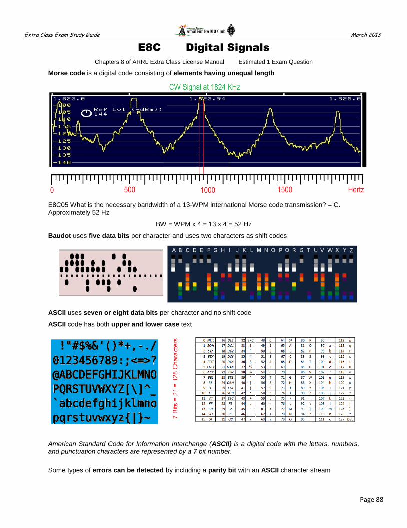
Extra Class Exam Study Guide March 2013
Page 88
E8C Digital Signals
Chapters 8 of ARRL Extra Class License Manual Estimated 1 Exam Question
Morse code is a digital code consisting of elements having unequal length
E8C05 What is the necessary bandwidth of a 13-WPM international Morse code transmission? = C. Approximately 52 Hz
BW = WPM x 4 = 13 x 4 = 52 Hz
Baudot uses five data bits per character and uses two characters as shift codes
ASCII uses seven or eight data bits per character and no shift code
ASCII code has both upper and lower case text
American Standard Code for Information Interchange (ASCII) is a digital code with the letters, numbers, and punctuation characters are represented by a 7 bit number.
Some types of errors can be detected by including a parity bit with an ASCII character stream

Extra Class Exam Study Guide March 2013
Page 89
Editors Note: Narrow band two state or digital modulation requires a bandwidth (BW) = (Constant Factor multiplied by Frequency Shift) plus the Baud rate. The constant factor depends on how much signal distortion. The constant commonly used for audio rates and amateur HF digital communications is 1.2.
E8C06 What is the necessary bandwidth of a 170-hertz shift, 300-baud ASCII transmission? = C. 0.5 kHz
BW = (Constant Factor x Shift) + Baud = (1.2 X 170 Hz) + 300 = (204) + 300 = 504 Hz
E8C07 What is the necessary bandwidth of a 4800-Hz frequency shift, 9600-baud ASCII FM transmission? = A. 15.36 kHz
BW = (Constant Factor x Shift) + Baud = (1.2 X 4800 Hz) + 9600 = (5760) + 9600 = 15,360 Hz
Spread-spectrum causes a digital signal to appear as wide-band noise to a conventional receiver
Direct sequence spread-spectrum (DSSS) communications technique uses a high speed binary bit stream to shift the phase of an RF carrier
Frequency hopping spread-spectrum (FHSS) communications technique alters the center frequency of a conventional carrier many times per second in accordance with a pseudo-random list of channels
Frequency hopping Spread-spectrum (FHSS) communication is a wide-bandwidth communications system in which the transmitted carrier frequency varies according to some predetermined sequence
JT-65 coding has the ability to decode signals which have a very low signal to noise ratio
Sinusoidal data pulses are used to minimize the bandwidth requirements of a PSK31 signal
In PSK31 (1's) are represented by a tone with no phase shift compared to the previous bit and (0's) are tone with a 180 degree phase shift relative to the phase of the previous bit. The phase shift occurs during the zero level modulation to minimize bandwidth. When the modulation level returns, the positions of the sine wave top and bottom are reversed from the previous bit. Thus the phase changes by 180 degrees while the frequency remains constant. – AD7FO

Extra Class Exam Study Guide March 2013
Page 90
E8D Waveforms
Chapters 7 of ARRL Extra Class License Manual Estimated 1 Exam Question
A wave consisting of an electric field and a magnetic field oscillating at right angles to each other is an electromagnetic wave
Changing electric and magnetic fields propagate the energy electromagnetic waves traveling in free space
Waves with a rotating electric field are circularly polarized electromagnetic waves
Peak-to-peak voltage is the easiest voltage amplitude parameter to measure when viewing a pure sine wave signal on an analog oscilloscope
Peak-to-peak voltage is the easiest voltage amplitude parameter to measure when viewing a pure sine wave signal on an analog oscilloscope
A peak-reading wattmeter gives a more accurate display of the output of a SSB phone transmitter
A peak-reading wattmeter should be used to monitor the output signal of a voice-modulated single-sideband transmitter to ensure you do not exceed the maximum allowable power

Extra Class Exam Study Guide March 2013
Page 91
E8D02 What is the relationship between the peak-to-peak voltage and the peak voltage amplitude of a symmetrical waveform? = B. 2:1
Vpp = 2 x Vp
E8D04 What is the PEP output of a transmitter that develops a peak voltage of 30 volts into a 50-ohm load? = B. 9 watts
W = E x I >> E = RMS (30 Vp) = 21.21 V >> I = E/R = 21.21 / 50 = 0.4242 A
W = E x I = 21.21 x 0.4242 = 8.997 W
E8D05 If an RMS-reading AC voltmeter reads 65 volts on a sinusoidal waveform, what is the peak-to-peak voltage? = D. 184 volts
Vpp = 2 xVp = 2 x (Vrms / 0.707) = 2 x (65 /0.707) = 2 x (91.94) = 183.88 Vpp
E8D11 What is the average power dissipated by a 50-ohm resistive load during one complete RF cycle having a peak voltage of 35 volts? = A. 12.2 watts
W = E x I >> E = RMS (35 Vp) = 24.745 V >> I = E/R = 24.745 / 50 = 0.4949 A
W = E x I = 24.745 x 0.4949 = 12.246 W
E8D12 What is the peak voltage of a sinusoidal waveform if an RMS-reading voltmeter reads 34 volts? = D. 48 volts
Vp = Vrms / 0.707 = 34 / 0.707 = 48.091 Vp
The typical value for the RMS voltage at a standard U.S. household power outlet is 120V AC
E8D13 Which of the following is a typical value for the peak voltage at a standard U.S. household electrical outlet? = B. 170 volts
Vp = Vrms / 0.707 = 120 / 0.707 = 169.731 Vp
E8D14 Which of the following is a typical value for the peak-to-peak voltage at a standard U.S. household electrical outlet? = C. 340 volts
Vpp = 2 xVp = 2 x (Vrms / 0.707) = 2 x (120 /0.707) = 2 x (169.731) = 339.463 Vpp
E8D16 What is the RMS value of a 340-volt peak-to-peak pure sine wave? = A. 120V AC
Vpp = 2 x Vp or Vp = Vpp / 2 = 340 / 2 = 170 Vp
Vrms = Vp x 0.707 = 170 x 0.707 = 120.19 Vrms

Extra Class Exam Study Guide March 2013
Page 92
E9A Antennas & Parameters
Chapter 9 of ARRL Extra Class License Manual Estimated 1 Exam Question
An ISOTROPIC antenna is a theoretical antenna used as a reference for antenna gain
An ISOTROPIC antenna has no gain in any direction
GAIN is the ratio of radiated signal strength in the direction of maximum radiation to a reference antenna
Radiation resistance + Ohmic resistance equal the total resistance of an antenna system
Antenna efficiency = (radiation resistance / total resistance) x 100%
Matching the feed point impedances minimize SWR on the transmission line
Antenna height, length/diameter ratio & location of conductive objects affect the feed point impedance
Antenna BANDWIDTH is the frequency range over which an antenna satisfies a performance requirement

Extra Class Exam Study Guide March 2013
Page 93
A folded dipole constructed from one wavelength of wire forming a very thin loop
A 1/2-wavelength dipole in free space 2.15 dB Gain over an isotropic antenna
A good radial system is a way to improve the efficiency of a ground-mounted quarter-wave vertical antenna
Soil conductivity determines ground losses for a ground-mounted vertical antenna operating in the 3-30 MHz range
E9A13 How much gain does an antenna have compared to a 1/2-wavelength dipole when it has 6 dB gain over an isotropic antenna? = A. 3.85 dB
Unknown Ant Gain – DP Gain >> 6 dBi – 2.15 dBi = 3.85 dB
E9A14 How much gain does an antenna have compared to a 1/2-wavelength dipole when it has 12 dB gain over an isotropic antenna? = B. 9.85 dB
Unknown Ant Gain – DP Gain >> 12 dBi – 2.15 dBi = 9.85 dB

Extra Class Exam Study Guide March 2013
Page 94
E9B Antenna Patterns
Chapter 9 of ARRL Extra Class License Manual Estimated 1 Exam Question
Numerical Electromagnetics Code (NEC) >> antenna modeling programs
Method of Moments is a computer program technique is commonly used for modeling antennas
Antenna modeling program can provide; Gain, SWR vs. frequency, Polar plots of the far-field Az & El patterns
Method of Moments analysis is a wire modeled as a series of segments with the same current
Decreasing the wire segments below 10 segments per half-wavelength may result in feed impedance errors
FAR-FIELD is the region where the shape of the antenna pattern is independent of distance
BEAMWIDTH is the angle between two points where the signal strength of the antenna is 3 dB less than max
The front-to-back ratio decreases if a YAGI is designed solely for maximum forward gain
If the boom of a YAGI is lengthened the gain increases
A directional antenna gain may change depending on frequency
The total radiation emitted by a directional gain antenna is the same as an isotropic antenna
E9B01 In the antenna radiation pattern in Figure E9-1, what is the 3-dB beamwidth? = B. 50 degrees
3 dB from Max Gain are shown in red at +/- 25° = 50°
E9B02 In the antenna radiation pattern shown in Figure E9-1, what is the front-to-back ratio? = B. 18 dB
Back = -18 dB >> Front = 0 dB >> the difference is 18 dB
E9B03 In the antenna radiation pattern shown in Figure E9-1, what is the front-to-side ratio? = B. 14 dB
Side = -14 dB >> Front = 0 dB >> the difference is 14 dB

Extra Class Exam Study Guide March 2013
Page 95
E9C Wire & Phased Vertical Antennas
Chapter 9 of ARRL Extra Class License Manual Estimated 1 Exam Question
E9C07 What type of antenna pattern over real ground is shown in Figure E9-2? = A. Elevation
E9C08 What is the elevation angle of peak response in the radiation pattern shown in Figure E9-2? = C. 7.5 degrees
E9C09 What is the front-to-back ratio of the radiation pattern shown in Figure E9-2? = B. 28 dB
E9C10 How many elevation lobes appear in the forward direction of the radiation pattern shown in Figure E9-2? = A. 4
A vertically polarized antenna low-angle radiation increases over seawater versus rocky ground
Placing a vertical antenna over an imperfect ground reduces low-angle radiation
A BEVERAGE antenna should be one or more wavelengths long
An UNTERMINATED RHOMBIC antenna is Bidirectional; four-sides, each WL long; open opposite the feed point
An HF TERMINATED RHOMBIC antenna requires a large physical area & 4 separate supports
The terminating resistor on a rhombic antenna provides a unidirectional radiation pattern

Extra Class Exam Study Guide March 2013
Page 96
E9C01 What is the radiation pattern of two 1/4-wavelength vertical antennas spaced 1/2-wavelength apart and fed 180 degrees out of phase? = D. A figure-8 oriented along the axis of the array
E9C02 What is the radiation pattern of two 1/4-wavelength vertical antennas spaced 1/4-wavelength apart and fed 90 degrees out of phase? = A. A cardioid
E9C03 What is the radiation pattern of two 1/4-wavelength vertical antennas spaced 1/2-wavelength apart and fed in phase? = C. A Figure-8 broadside to the axis of the array

Extra Class Exam Study Guide March 2013
Page 97
E9D Directional Antennas
Chapter 9 of ARRL Extra Class License Manual Estimated 1 Exam Question
A linearly polarized Yagi antennas be used to produce circular polarization by arranging two Yagis perpendicular to each other with the driven elements at the same point on the boom and fed 90 degrees out of phase
Antenna beamwidth decreases as the gain increases
Tracking a satellite in orbit the ground antenna moves in both azimuth and elevation
HF mobile antenna >> Resistance decreases & Capacitive increases as the frequency decreases
To minimize losses an HF mobile antenna loading coil have a high ratio of reactance to resistance

Extra Class Exam Study Guide March 2013
Page 98
Place a high-Q loading coil at center of the vertical radiator to minimize losses in a shortened antenna
Multiband operation is an advantage of using a trapped antenna
A multiband trapped antenna might radiate harmonics
Loading coils used with an HF mobile antenna to cancel capacitive reactance
The bandwidth decreases in an antenna shortened through the use of loading coils
Top loading in a shortened HF vertical antenna improves radiation efficiency
The feed point impedance of a folded dipole antenna is 300 ohms
Best RF station ground >> short connection to 3 or 4 interconnected ground rods driven into the Earth
A wide flat copper strap is best for minimizing losses in a station's RF ground system
Gain increases 6 dB on a parabolic dish antenna when the operating frequency is doubled

Extra Class Exam Study Guide March 2013
Page 99
E9E Matching
Chapter 9 of ARRL Extra Class License Manual Estimated 1 Exam Question
The delta matching system matches a high-impedance transmission line to a lower impedance antenna by connecting the line to the driven element in two places spaced a fraction of a wavelength each side of element center
The gamma match that matches an unbalanced feed line to an antenna by feeding the driven element both at the center of the element and at a fraction of a wavelength to one side of center
A Gamma match is an effective match of a 50-ohm feed to a grounded tower so it can be a vertical antenna
The series capacitor in a gamma matching network cancels the inductive reactance of the matching network
The stub match uses a section of transmission line connected in parallel with the feed line at or near the feed point
The universal stub matching technique is an effective way of matching a feed line to a VHF or UHF antenna when the impedances of both the antenna and feed line are unknown
The driven element must be capacitive in a 3-element Yagi be tuned to use a hairpin matching system
An L network is the equivalent network for a hairpin matching system on a 3-element Yagi

Extra Class Exam Study Guide March 2013
Page 100
An SWR greater than 1:1 is a characteristic of a mismatched transmission line
Reflection coefficient describes the interactions at the load end of a mismatched transmission line
Insert a 1/4-wavelength piece of 75-ohm coaxial cable transmission line in series between the antenna and the 50-ohm feed cable to match an antenna with 100-ohm feed point impedance to a 50-ohm coaxial cable feed line
The primary purpose of a phasing line when used with an antenna having multiple driven elements is to ensure that each driven element operates in concert with the others to create the desired antenna pattern
A Wilkinson divider divides power equally among multiple loads while preventing changes in one load from disturbing power flow to the others

Extra Class Exam Study Guide March 2013
Page 101
E9F Transmission Lines
Chapter 9 of ARRL Extra Class License Manual Estimated 1 Exam Question
Velocity factor of a transmission line is the transmission line velocity divided by the velocity of light in a vacuum
VELOCITY FACTOR is the ratio of a signal speed through a transmission line to the speed of light in a vacuum
Dielectric determines the velocity factor of a transmission line
Electrical signals move more slowly in a coaxial cable than in air
The significant differences between foam-dielectric coaxial cable and solid-dielectric cable are; reduced safe operating voltage limits, reduced losses per unit of length and higher velocity factor
Coaxial cable with solid polyethylene dielectric 0.66 is the typical velocity factor
Ladder line has lower loss than coaxial cable such as RG-58 at 50 MHz?
E9F05 What is the approximate physical length of a solid polyethylene dielectric coaxial transmission line that is electrically one-quarter wavelength long at 14.1 MHz? = C. 3.5 meters
VF x WL/4 = 0.66 x (300 / 14.1) / 4 = 0.66 x (21.28 / 4) = 0.66 x 5.319 = 3.511 M
E9F06 What is the approximate physical length of an air-insulated, parallel conductor transmission line that is electrically one-half wavelength long at 14.10 MHz? = C. 10 meters
VF x WL/2 = 0.95 x (300 / 14.1) / 2 = 0.95 x (21.28 / 2) = 0.95 x 10.64 = 10.11 M
E9F09 What is the approximate physical length of a solid polyethylene dielectric coaxial transmission line that is electrically one-quarter wavelength long at 7.2 MHz? = B. 6.9 meters
VF x WL/4 = 0.66 x (300 / 7.2) / 4 = 0.66 x (41.66 / 4) = 0.66 x 10.417 = 6.875 M

Extra Class Exam Study Guide March 2013
Page 102
E9G Smith Charts
Chapter 9 of ARRL Extra Class License Manual Estimated 1 Exam Question
Impedance along transmission lines can be calculated using a Smith chart
Resistance circles and reactance arcs coordinate system is used in a Smith chart
Resistance and reactance are the two families of circles and arcs that make up a Smith chart
The arcs on a Smith chart represent Points with constant Reactance
Impedance and SWR values in transmission lines are often determined using a Smith chart
The wavelength scales on a Smith chart calibrated in fractions of transmission line electrical wavelength
Reassigning impedance values with regard to the prime center is the process of normalization on a Smith chart

Extra Class Exam Study Guide March 2013
Page 103
E9G06 On the Smith chart shown in Figure E9-3, what is the name for the large outer circle on which the reactance arcs terminate? = B. Reactance axis
E9G07 On the Smith chart shown in Figure E9-3, what is the only straight line shown? = D. The resistance axis
< Figure E9-3
Standing-wave ratio circles is the third family of circles is often added to a Smith chart solving problems
Think about it as moving around the Smith Chart which is 1/2 a wavelength all the way around (180 degrees). If we move 90° on the smith chart our transmission line does the opposite of our input, so a short at 90º will appear as an open to the generator (transmitter input) end and an open will look like a short. Moving to ½ wavelength or 180º brings us back to the starting point so there is no opposite transformation, therefore a short at the output will look like a short at the input and an open will look like an open. For partial wavelengths the impedance between 0 and ¼ wavelength the line will look like an inductive reactance and for a ¼ to ½ wavelength the line will look like a capacitive reactance depending on the actual fractional wavelength. – AD7FO

Extra Class Exam Study Guide March 2013
Page 104
E9H ERP, Gain, Loss
Chapter 9 of ARRL Extra Class License Manual Estimated 1 Exam Question
Decibel (dB) is a ratio expressed as a log of 10 or Gain/loss ratio = 10^(dB/10)
Ratios e.g.,2 = 3db =10^(dB/10) = 10^(3/10) = 10^0.3 = 2 >> 0dB=1, 1dB=1.26, 2dB=1.58, 3dB=2, -6dB=1/4
Watts e.g., 1 milliwatt = −30 dBW, 1 watt = 0 dBW, 10 watts = 10 dBW, 100 watts = 20 dBW, and 1,000 W = 30 dBW dBi >> dB (isotropic) – the gain of an antenna compared with the hypothetical isotropic antenna
dBd >> dB (dipole) – the gain of an antenna compared with a half-wave dipole antenna. 0 dBd = 2.15 dBi
EFFECTIVE RADIATED POWER describes station output, including the transmitter, antenna and everything in between, when considering transmitter power and system gains and losses
E9H01 What is the effective radiated power relative to a dipole of a repeater station with 150 watts transmitter power output, 2-dB feed line loss, 2.2-dB duplexer loss and 7-dBd antenna gain? = D. 286 watts
ERP = Power X (Gain - Loss)
ERP = 150W X (7.0 - 2.0 - 2.2) dB
ERP = 150W X 2.8dB
Head math check 3dB is about 2 ratio so the answer is about 300W
2.8dB = Gain/loss ratio = 10^(dB/10)or 10^(2.8/10) or 10^.28 or 1.905
ERP = 150W X 1.905
ERP = 285.75W
E9H02 What is the effective radiated power relative to a dipole of a repeater station with 200 watts transmitter power output, 4-dB feed line loss, 3.2-dB duplexer loss, 0.8-dB circulator loss and 10-dBd antenna gain? = A. 317 watts
ERP = Power X (Gain - Loss)
ERP = 200W X (10.0 - 4.0 - 3.2 – 0.8) dB
ERP = 200W X 2.0dB
Head math check 2dB is about 1.5 ratio so the answer is about 300W
2.0dB = Gain/loss ratio = 10^(dB/10)or 10^(2.0/10) or 10^.20 or 1.584
ERP = 200W X 1.584
ERP = 316.80 W

Extra Class Exam Study Guide March 2013
Page 105
E9H03 What is the effective isotropic radiated power of a repeater station with 200 watts transmitter power output, 2-dB feed line loss, 2.8-dB duplexer loss, 1.2-dB circulator loss and 7-dBi antenna gain? = B. 252 watts
ERP = Power X (Gain - Loss)
ERP = 200W X (7.0 - 2.0 - 2.8 – 1.2) dB
ERP = 200W X 1.0dB
Head math check 1dB is about 1.2 ratio so the answer is about 240W
1.0dB = Gain/loss ratio = 10^(dB/10)or 10^(1.0/10) or 10^.10 or 1.2589
ERP = 200W X 1.2589
ERP = 251.78 W
Editors Comment: There is another way to work these problems
by converting the transmitter power to dBW.
Here is the same problem as above in all dB math.
You will get the same answer, see if it is easier for you.
ERP = Power + Gain - Loss
ERP = (200W) + 7.0 - 2.0 - 2.8 – 1.2
ERP = 23.0103 dBw + 7.0 - 2.0 - 2.8 – 1.2
ERP = 24.0103 dBW
24.0103 dBW = 10^(dB/10)or 10^(24.0103/10) or 10^2.40103 or 251.7851 Watts
ERP = 251.78 W
This method is good for complex transmission paths
you just add and subtract dBs and only convert at the TX end

Extra Class Exam Study Guide March 2013
Page 106
E9H Direction Finding Antennas
Chapter 9 of ARRL Extra Class License Manual Estimated 1 Exam Question
The main drawback of a wire-loop antenna for direction finding is the bidirectional pattern
A cardioid-pattern antenna has a very sharp single null useful for direction finding
A sense antenna modifies the pattern of a DF antenna array to provide a null in one direction
The triangulation method uses headings from several different receiving locations to locate a signal
An RF attenuator prevents receiver overload making it difficult to determine peaks or nulls
RECEIVING LOOP ANTENNA >> One or more turns of wire wound in the shape of a large open coil
The output loop antenna be increased by adding turns in the loop or add area to the loop
Shielded loop antenna is electro-statically balanced against ground, giving better nulls

Extra Class Exam Study Guide March 2013
Page 107
INDEX
A 3rd order intercept ............... 46 AC circuits ............................ 57 AC energy in real circuits ..... 57 AC measurements ................ 84 AC waveforms ...................... 84 Active audio filters ................ 80 Active filters .......................... 80 Administration of exams ....... 24 Amateur radio in space ........ 27 Amateur radio safety ............ 10 Amateur Satellite service ...... 22 Amateur satellites ................. 27 Amplifiers .............................. 71 Analog instruments ............... 39 Angles, antenna take-off ...... 95 Antenna analyzers ................ 39 Antenna Beam width ............ 92 Antenna beam width ............. 97 Antenna design..................... 94 Antenna Efficiency ................ 92 Antenna efficiency ................ 97 Antenna elevation ................. 95 Antenna Gain........................ 92 Antenna gain ........................ 97 Antenna ground effects ........ 95 Antenna grounding ............... 97 Antenna Losses .................... 97 Antenna mobile..................... 97 Antenna parameters ............. 92 Antenna patterns .................. 94 Antenna shortened ............... 97 Antenna structure restriction 17 Antenna SWR bandwidth ..... 97 Antenna take-off angles ....... 95 Antennas DF ......................... 104 Antennas matching ............... 99 APRS .................................... 32 Audio filters ........................... 80 Aurora propagation ............... 37 Automatic control operation .. 21 Automatic message forward . 15 Auxiliary stations................... 25 B Balanced modulators ............ 77 Basic circuit design ............... 80 Beam width antenna ............. 92 Beam width, antenna ............ 97 Beverage antennas .............. 95 Blocking dynamic range ....... 46 Business communications .... 25 C Capture effect ....................... 43 Cathode-ray tube .................. 64 CEPT licenses ...................... 25 Charge-coupled devices ....... 64
C con’t Class of amplifiers................. 71 CMOS ................................... 59 CMOS integrated circuits ...... 63 Coax feed lines ..................... 101 Compensated comm ............. 25 Contest operating.................. 31 Control Opr reimbursement .. 17 Control Opr responsibilities ... 21 Coordinate systems .............. 57 Core material ........................ 64 Counters ............................... 79 Cross-modulation interfer ..... 46 Crystal filters ......................... 66 Crystal oscillators .................. 66 CW ........................................ 88 D DDS ...................................... 82 Demodulation ........................ 77 Demodulation ........................ 86 Depletion mode transistor ..... 59 Desensitization ...................... 46 Detectors ............................... 77 DF antennas ......................... 104 Digital circuit .......................... 69 Digital circuits ........................ 69 Digital instruments ................ 39 Digital logic ............................ 63 Digital modes ........................ 88 Digital modes HF .................. 33 Digital error correction .......... 33 Digital modes UHF ................ 32 Digital modes VHF ................ 32 Digital signals ........................ 88 Digital waveforms.................. 84 Diodes ................................... 61 Direct digital synthesizers ..... 82 Direction finding antennas .... 104 Directional antennas ............. 97 Distortion, amplifiers ............. 71 Dividers, power ..................... 99 DSP ....................................... 77 DSP demodulation ................ 77 DSP filtering .......................... 73 DSP modulation .................... 77 DSP noise reduction ............. 48 DX operating ......................... 31 E E H plane patterns ................ 94 E patterns .............................. 94 Earth-Moon-Earth comm ...... 34 Effective radiated power ....... 104 Effects grd on propagation .... 37 Efficiency, antenna................ 92 Efficiency, antenna................ 97 Electrical appliance noise ..... 48
E con’t Electrical length feed lines ... 101 Electromagnetic fields .......... 57 Electrostatic fields ................ 57 Elevation above real ground 95 Emission standards .............. 15 Enhancement mode transistor 59 ERIP ..................................... 104 ERP ...................................... 104 Error correction HF digital .... 33 Exam documentation............ 24 Exam question pools ............ 24 Examiner definitions ............. 24 External RF amplifiers .......... 25 F Fast scan television .............. 29 FDMA ................................... 86 Feed lines ............................. 101 Feed lines 1/2 wavelength ... 101 Feed lines 1/4 wavelength ... 101 Feed lines 1/8 wavelength ... 101 Feed lines matching ............. 99 FET ....................................... 59 Field-effect transistors .......... 59 Filter applications ................. 73 Filter characteristics ............. 73 Filters crystal ........................ 66 Filters networks .................... 73 Flat terrain ............................ 37 Foreign communications ...... 25 Frequency counters.............. 79 Frequency divider circuits .... 79 Frequency dividers ............... 69 Frequency division multiplex 86 Frequency marker generator 79 Frequency markers .............. 79 Frequency privileges ............ 15 Frequency sharing ................ 15 G Gain antennas ...................... 97 Gain as a function of pattern 94 Gain, antenna ....................... 92 Gates Logic .......................... 63 General operating restriction 17 Gray-line ............................... 35 Ground effects ...................... 95 Ground effects, antennas ..... 95 Grounding ............................. 90 Grounding antennas ............. 97 H H patterns ............................. 94 Half-power bandwidth........... 49 Hazardous materials ............ 10 HF digital modes .................. 33

Extra Class Exam Study Guide March 2013
Page 108
I IARP licenses ....................... 25 Image rejection ..................... 43 Impedance coordinates ........ 53 Impedance matching ............ 73 Impedance matching feeds .. 101 Impedance plots ................... 53 Information rate vs. BW ........ 88 Instrument accuracy ............. 41 Instrument calibration ........... 41 Integrated circuits ................. 63 Intermodulation ..................... 46 Intermodulation, amplifiers ... 71 Irregular waveforms .............. 84 Isotropic antennas ................ 92 J K L Junction transistor ................ 59 Line noise ............................. 48 Liquid crystal displays .......... 64 Local Control restrictions ...... 21 Locating noise sources ......... 48 Logic circuits ......................... 69 Logic elements ..................... 69 Logic gates ........................... 63 Long path .............................. 35 Losses, antenna ................... 97 M Markers ................................. 79 Matching ............................... 99 Matching antennas ............... 99 Matching feed lines .............. 99 Matching networks ............... 73 MDS ...................................... 43 Measurement errors ............. 41 Measurement limitations ...... 41 Measurement of "Q" ............. 41 Measurements ...................... 90 Meteor Scatter ...................... 34 Microwave amplifiers ............ 71 Mixer stages ......................... 77 MMIC .................................... 66 Mobile antennas ................... 97 Modulation ............................ 77 Modulation & Demodulation . 77 Modulation deviation ratio .... 86 Modulation index& dev ratio . 86 Modulation methods ............. 86 Modulation methods ............. 88 Monolithic amplifiers ............. 66 MOS ..................................... 59 Multi-path propagation .......... 35 N National quiet zone ............... 25 N-channel ............................. 59 Negative logic ....................... 69 Network analyzers ................ 39 Networks impedance match . 73 Noise blanker........................ 48 Noise floor ............................ 43
N con’t Noise suppression ................ 48 NPN ...................................... 59 N-type transistor .................... 59 O Op-amps ............................... 80 Open feed lines ..................... 101 Open-wire feed lines ............. 101 Operating frequency ............. 31 Operating Standards ............. 15 Operational amplifiers ........... 80 Optical components .............. 68 Optical couplers .................... 68 Optical devices ...................... 64 Optical sensors ..................... 68 Opto-Isolators ....................... 68 Orbital mechanics ................. 27 Oscillators ............................. 82 Oscillators crystal .................. 66 Oscilloscopes ........................ 39 P Parallel resonance ................ 49 Parameters antennas ........... 92 Parasitic suppression, amp ... 71 P-channel .............................. 59 Peak of RF signals ................ 84 Peak-to-peak values ............. 90 PEP of RF signals ................. 84 Permeability .......................... 64 Phase angle V & I ................. 51 Phase angles parallel Ckt ..... 51 Phase angles series Ckt ....... 51 Phase modulators ................. 77 Phase noise .......................... 43 Phase reactive circuits .......... 49 Phase relationships............... 51 Phased vertical antennas ..... 95 Phase-locked loops............... 82 Photoconductive principles ... 68 Photovoltaic systems ............ 68 Piezoelectric crystals ............ 66 Plotting impedances Polar .... 53 Plotting impedances Rect ..... 53 PM ......................................... 86 PNP ....................................... 59 Polar coordinates .................. 53 Polarization ........................... 90 Positive logic ......................... 69 Power dividers ...................... 99 Power factor .......................... 57 Power supplies ...................... 75 Power systems ...................... 68 PPL ....................................... 82 Preselection .......................... 46 Probes ................................... 41 Propagation ........................... 34 Propagation ........................... 35 Propagation ........................... 37
P con’t Propagation modes .............. 37 P-type transistor ................... 59 Pulse modulation .................. 86 Pulse waveforms .................. 84 Q Q factor ................................. 49 Q Measurement .................... 41 Quartz crystals ..................... 66 R RACES operations ............... 17 Radiation pattern .................. 92 Radiation reactance ............. 92 Radiation resistance ............. 92 Radio-path horizon ............... 37 RC Time constants ............... 51 Reactance ............................ 77 Reactive power ..................... 57 Receiver performance .......... 43 Receiver performance .......... 46 Reciprocal privileges ............ 25 Rectangular coordinates ...... 53 Reference antennas ............. 92 Remote control operation ..... 21 Resonance ........................... 49 Resonant circuits .................. 49 Resonant rhombic antennas 95 Restricted Station location ... 17 RF circuits ............................ 57 RF energy in real circuits ..... 57 RF grounding ........................ 90 RF measurements ................ 39 RF radiation hazards ............ 10 Rhombic antennas ............... 95 RL Time constants ............... 51 RLC definition ....................... 51 RLC time constants .............. 51 RMS of RF signals ............... 84 S Safety ................................... 10 Satellite antennas ................. 97 Satellite frequencies modes . 27 Satellite hardware ................. 27 Satellite operations ............... 27 Satellite service definitions ... 22 Saw tooth waveforms ........... 84 SDR ...................................... 77 Selecting ............................... 64 Selective fading .................... 37 Selectivity ............................. 43 Semiconductor devices ........ 59 Semiconductor diodes .......... 61 Semiconductor germanium .. 59 Series resonance ................. 49 Shorted feed lines ................ 101 Shortened antennas ............. 97 Signal-to-noise-ratio ............. 43 Silicon ................................... 59 Sine waveforms .................... 84

Extra Class Exam Study Guide March 2013
Page 109
S con’t Skin effect ............................. 57 Sloping terrain ...................... 37 Slow scan television ............. 29 Smith chart ........................... 102 Software defined radio ......... 77 Solid-state amplifiers ............ 71 Space stations frequencies .. 22 Space stations licenses ........ 22 Space stations notification .... 22 Space stations restrictions ... 22 Space stations provisions ..... 22 Special temporary authority .. 25 Spectrum analyzers .............. 39 Spread Spectrum ................. 25 Spread-spectrum Restrict ..... 88 Spread-Spectrum Tx ............ 31 Spurious emissions .............. 17 Spurious suppression, amp .. 71 Square waveforms ............... 84 Standard antennas ............... 92 Station control....................... 21 Station control definitions ..... 21 Station restrictions ................ 17 Station special operations .... 17 Stations aboard Aircraft ........ 15 Stations aboard Ships .......... 15 SWR bandwidth, antenna ..... 97 Synthesizers ......................... 82 System gains ........................ 104 System losses ...................... 104 System noise ........................ 48 T Take-off angle....................... 37 Take-off angles, antennas .... 95 TDMA ................................... 86 Tele-command...................... 22 Telemetry .............................. 22 Television ............................. 29 Terminated Rhombic ............ 95 Test equipment ..................... 39 Testing transistors ................ 39 Third party communications . 25 Time constants ..................... 51 Time constants in RC Ckt ..... 51 Time constants in RL Ckt ..... 51 Time division multiplexing .... 86 Toroids .................................. 64 Trans-equatorial ................... 35 Transistor types .................... 59 Transistors testing ................ 39 Transmission lines ................ 101 Truth tables ........................... 69 TTL integrated circuits .......... 63 Types of filters ...................... 73 Types of networks ................ 73
U V UHF digital modes ................ 32 Vacuum tube amplifiers ........ 71 VEC ....................................... 24 VEC accreditation ................. 24 VEC Preparation ................... 24 VEC Qualifications ................ 24 Velocity factor feed lines ....... 101 Vertical antennas .................. 95 VHF digital modes................. 32 Voltage regulators ................. 75 Volunteer examiner program 24 W X Y Z Waves ................................... 90 Winding ................................. 64 Wire antennas ....................... 95 YAGI antennas ...................... 94