exterior insulation: strategies and cladding attachment...exterior insulation and cladding...
TRANSCRIPT

11/17/2017
1
Exterior Insulation:Strategies and Cladding Attachment
Peter Baker
November 16, 2017
Exterior Insulation and Cladding Attachment
Overview• Building Insulation Retrofit Strategies• Exterior Insulation Approaches
– Insulation and Separate Cladding– Exterior Insulation and Finish System (EIFS)– Insulated Metal Panels
• Cladding Attachment Research
Exterior Insulation and Cladding Attachment
Insulation Retrofit Options
Exterior Insulation and Cladding Attachment
Insulation Retrofit
• Existing buildings are often un‐insulated/poorly insulated
• Insulation options are:– Cavity fill– Interior insulation– Exterior insulation

11/17/2017
2
Exterior Insulation and Cladding Attachment
Cavity Fill Insulation
• Cavity fill insulation is most common retrofit –but has limitations– 4” cavity for older wood frame– ¾” cavity for mass masonry
Exterior Insulation and Cladding Attachment
Interior Insulation
• Interior insulation retrofit concerns– Continuity of insulation (partition walls, floors, etc.)– Loss of floor space– Occupant disruption
• Desirable if exterior appearance is needed/wanted to be maintained
• Often the best approach for historic buildings• Not ideal from a building physics perspective
Exterior Insulation and Cladding Attachment
Exterior Insulation
• Exterior insulation retrofit– Ideal from a building physics perspective– Can be completed with less disruption to occupants– May come at a higher cost than other approaches
Exterior Insulation and Cladding Attachment
• New approach!• New approach?• Not a new approach…• Pesky Canadians…
• Benefits discussed in Canadian Building Digests produced by the National Research Council of Canada in the 1960’s
Exterior Insulation

11/17/2017
3
Exterior Insulation and Cladding Attachment
• CBD 44 (W.P. Brown, A.G. Wilson) – Published in 1963
“Application of insulation over the entire exterior of a wall provides an ideal solution to the problems presented by thermal bridges.”
“It should be stressed that many of the thermal bridges occurring in present‐day construction can be avoided, or their effects minimized, if they are recognized in the early stages of design.”
Exterior Insulation
Exterior Insulation and Cladding Attachment
• The “Perfect” Wall
• Increase overall thermal performance
• Minimize thermal bridges• Minimize potential
for air leakagecondensation
• Improve air tightness?• Improve rainwater
management?
Exterior Insulation
Exterior Insulation and Cladding Attachment
1980s ON – a “weird” builder
Exterior Insulation and Cladding Attachment
1990s ON – a “good” builder

11/17/2017
4
Exterior Insulation and Cladding Attachment
2000s ON – a “typical” builder
Exterior Insulation and Cladding Attachment
Exterior Insulation Approaches
Exterior Insulation and Cladding Attachment
Exterior Insulation Approaches
• Insulation and cladding (discrete components)
Exterior Insulation and Cladding Attachment
• Insulation and cladding (discrete components)
• Exterior Insulation and Finish System (EIFS)
Exterior Insulation Approaches

11/17/2017
5
Exterior Insulation and Cladding Attachment
• Insulation and cladding (discrete components)
• Exterior Insulation and Finish System (EIFS)
• Insulated Metal Panels (IMP)– Used as a complete enclosure
Exterior Insulation Approaches
Exterior Insulation and Cladding Attachment
• Insulation and cladding (discrete components)
• Exterior Insulation and Finish System (EIFS)
• Insulated Metal Panels (IMP)– Used as a complete enclosure– Used as an insulated cladding
Exterior Insulation Approaches
Exterior Insulation and Cladding Attachment
Brick Veneer
• Brick veneer has some of the longest history with exterior insulation– Long history = more common– More common = less questions
• Not always well done
Exterior Insulation and Cladding Attachment
Brick Veneer

11/17/2017
6
Exterior Insulation and Cladding Attachment
Brick Veneer
Exterior Insulation and Cladding Attachment
Brick Veneer
Exterior Insulation and Cladding Attachment
Brick Veneer
Exterior Insulation and Cladding Attachment
• Alternate details and support options exist• Support systems for brick can be modified for other building elements– Decks– Balconies– Canopies– Etc.
Brick Veneer

11/17/2017
7
Exterior Insulation and Cladding Attachment
Brick Veneer
Exterior Insulation and Cladding Attachment
Brick Veneer
Exterior Insulation and Cladding Attachment
Other Claddings• For insulation less than 1.5” – direct attachment of cladding
though insulation back to the structure is practical• For insulation greater than 2” – a secondary cladding
support structure is often needed.
Exterior Insulation and Cladding Attachment
• Lighter weight claddings (metal/wood/fiber cement)– Less common = less experience– Less experience = more questions
• Cladding support systems historically done poorly
• Systems are getting better
Other Claddings

11/17/2017
8
Exterior Insulation and Cladding Attachment
• Single “z‐furring”– Poor thermal performance (steel stud wall on the exterior – why bother?)
Other Claddings
Exterior Insulation and Cladding Attachment
Other Claddings
Exterior Insulation and Cladding Attachment
• Single “z‐furring”• Double “z‐furring”
– Can be made to function reasonably well provided that two layers of insulation are used.
– Often designed with first layer bridging insulation and second layer creating a gap behind the cladding = single “z‐furring”
Other Claddings
Exterior Insulation and Cladding Attachment
• Single “z‐furring”• Double “z‐furring”
Other Claddings

11/17/2017
9
Exterior Insulation and Cladding Attachment
• Single “z‐furring”• Double “z‐furring”• Clip and “z‐furring” or hat channel– Metal clip– Fiberglass clip
Other Claddings
Exterior Insulation and Cladding Attachment
Other Claddings
Exterior Insulation and Cladding Attachment
• Single “z‐furring”• Double “z‐furring”• Clip and “z‐furring” or hat channel– Metal clip– Fiberglass clip
• Attach furring directly back to structure through insulation
Other Claddings
Exterior Insulation and Cladding Attachment
Other Claddings

11/17/2017
10
Exterior Insulation and Cladding Attachment
EIFS
• Exterior Insulation and Finish System (EIFS)– Lightweight– Cost effective– Water managed
• Minimal Thermal Bridging• R‐4 per inch• System has a tainted history
Exterior Insulation and Cladding Attachment
• Commonly installed using adhesive
• The adhesive can also form the drainage gap in water managed systems
EIFS
Exterior Insulation and Cladding Attachment
EIFS
Exterior Insulation and Cladding Attachment
Insulated Metal Panels
• Insulated Metal Panels (IMP)– Lightweight– Moderate cost– Water managed
• Minimal Thermal Bridging• R‐7.5+ per inch• Can be an excellent enclosure system
• Requires some consideration for retrofit applications
11/17/2017
11
Exterior Insulation and Cladding Attachment
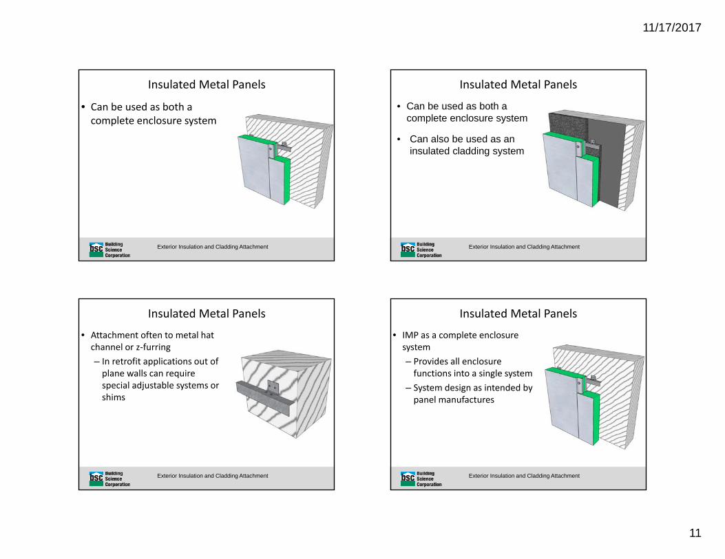
• Can be used as both a complete enclosure system
Insulated Metal Panels
Exterior Insulation and Cladding Attachment
• Can be used as both a complete enclosure system
• Can also be used as an insulated cladding system
Insulated Metal Panels
Exterior Insulation and Cladding Attachment
• Attachment often to metal hat channel or z‐furring– In retrofit applications out of plane walls can require special adjustable systems or shims
Insulated Metal Panels
Exterior Insulation and Cladding Attachment
• IMP as a complete enclosure system– Provides all enclosure functions into a single system
– System design as intended by panel manufactures
Insulated Metal Panels

11/17/2017
12
Exterior Insulation and Cladding Attachment
• IMP as a complete enclosure system– May require special detailing for compartmentalization at floors or partition walls, particularly in retrofit applications
Insulated Metal Panels
Exterior Insulation and Cladding Attachment
• IMP as an insulated cladding system– Provides thermal insulation and cladding
– Rain water management and air tightness are provided by other elements
– Modification to manufacturers intended design
Insulated Metal Panels
Exterior Insulation and Cladding Attachment
Insulated Metal Panels (Retrofits)
• IMP as an insulated cladding system– Need to fill space between the panel and back up wall to prevent air by‐pass of the insulation
– Can simplify certain details such as interfaces at balconies, lower roofs, and compartmentalization
– More in line with common construction detailing
Exterior Insulation and Cladding Attachment
Cladding Support System:Direct Attachment Through
Insulation

11/17/2017
13
Exterior Insulation and Cladding Attachment
Background• Industry trend to using exterior rigid insulation
– Increased thermal value– Condensation resistance– Increased air tightness (possibly)– Increased rainwater management (possibly)
• Need to develop a means to attach cladding over thick layers of exterior insulation that can meet the following requirements:– Provides good thermal performance– Low cost– Easy to construct/install (low cost)
Exterior Insulation and Cladding Attachment
• Current pneumatic nailers have maximum fastener lengths of 3” to 3.5” which limits insulation thicknesses to 1.5” max– 3.5” fastener, ¼” to ½” siding, 1 ½” embedment (3.5‐0.5‐1.5 = 1.5” max insulation)
• Therefore, for insulation greater than 1.5” direct attachment of cladding though the insulation back to the structure is often not practical
Background
Exterior Insulation and Cladding Attachment
Direct Attachment Through Insulation
Wood structure
2” to 4” of exterior rigid insulation
1x3 wood furring strips
Masonry Structure
2x4 framing attached to surface of masonry
2” to 4” of exterior rigid insulation
1x3 wood furring strips
Exterior Insulation and Cladding Attachment
Direct Attachment Through Insulation

11/17/2017
14
Exterior Insulation and Cladding Attachment
• Lots of practical experience with this approach for lightweight cladding systems over thick layers of insulation (several decades).
• Approach has demonstrated very good long term performance• High resistance from industry
– Compression resistance of insulation– Long term creep
Direct Attachment Through Insulation
Exterior Insulation and Cladding Attachment
“Myths”
• “Does the insulation crush under load?”• YES!• Loading a system until failure (500lbs to 1000lbs or more per screw fastener) will crush most rigid insulations
…..Unfortunately that is the wrong question
Exterior Insulation and Cladding Attachment
• “Does the insulation crush under a load similar to what will be imposed on it in a cladding support application?”
• The answer is no!...
Context is important
“Myths”
Exterior Insulation and Cladding Attachment
Typical Loads• Typical cladding weights (psf)
low high
Vinyl 0.6 1.0
wood 1.0 1.5
fiber cement 3.0 5.0
stucco 10.0 12.0
adhered stone veneers 17.0 25.0
11/17/2017
15
Exterior Insulation and Cladding Attachment
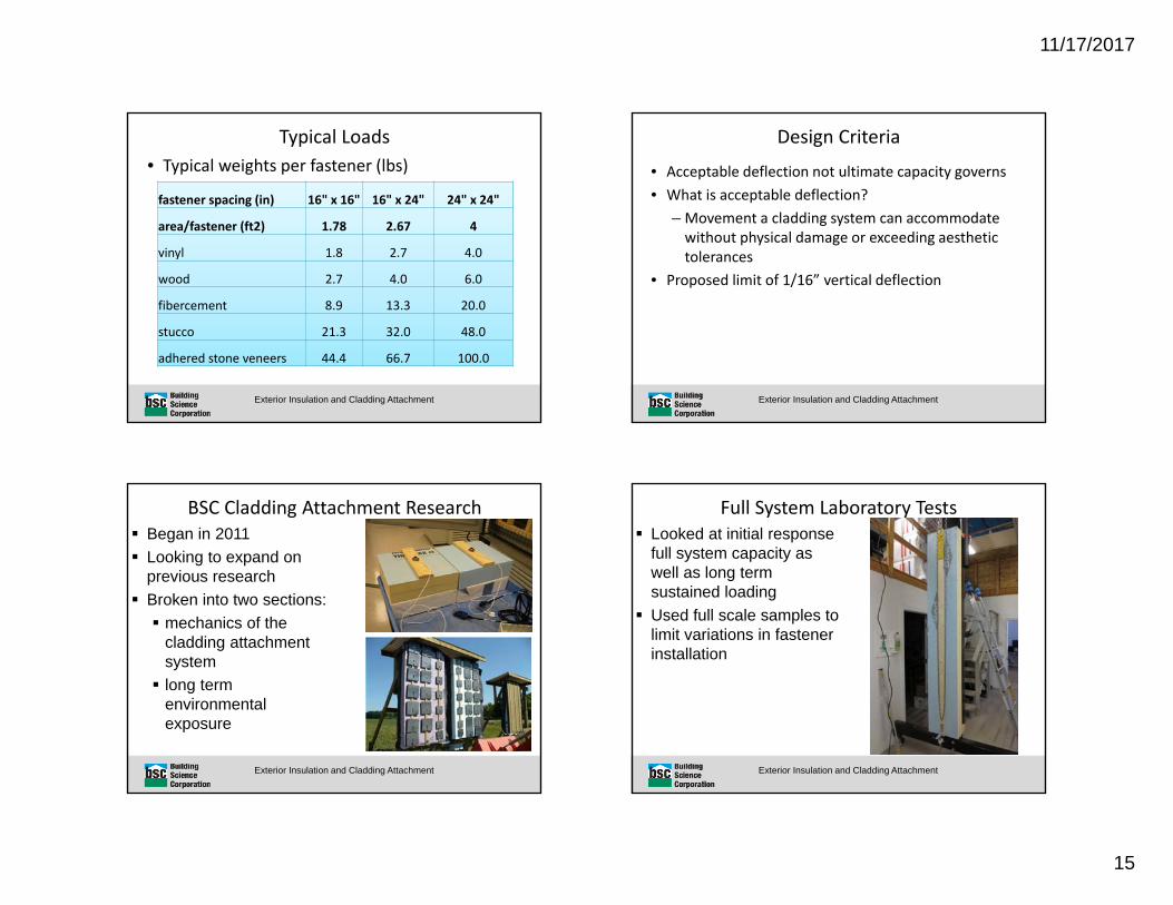
Typical Loads• Typical weights per fastener (lbs)
fastener spacing (in) 16" x 16" 16" x 24" 24" x 24"
area/fastener (ft2) 1.78 2.67 4
vinyl 1.8 2.7 4.0
wood 2.7 4.0 6.0
fibercement 8.9 13.3 20.0
stucco 21.3 32.0 48.0
adhered stone veneers 44.4 66.7 100.0
Exterior Insulation and Cladding Attachment
Design Criteria
• Acceptable deflection not ultimate capacity governs• What is acceptable deflection?
– Movement a cladding system can accommodate without physical damage or exceeding aesthetic tolerances
• Proposed limit of 1/16” vertical deflection
Exterior Insulation and Cladding Attachment
BSC Cladding Attachment Research Began in 2011 Looking to expand on
previous research Broken into two sections: mechanics of the
cladding attachment system long term
environmental exposure
Exterior Insulation and Cladding Attachment
Full System Laboratory Tests Looked at initial response
full system capacity as well as long term sustained loading
Used full scale samples to limit variations in fastener installation

11/17/2017
16
Exterior Insulation and Cladding Attachment
Full System Laboratory Tests Results Insulation type not a
significant influence on system capacity
System capacity is a function of the number of fasteners used
High measured capacities and stable performance under controlled environmental conditions
Exterior Insulation and Cladding Attachment
0
50
100
150
200
250
300
350
400
450
500
550
600
650
700
750
800
850
900
950
1000
0.00 0.02 0.03 0.05 0.06 0.08 0.09 0.11 0.12 0.14 0.15 0.17 0.18 0.20 0.21 0.23 0.24
Load
(lbs)
deflection (in)
Total Load vs. Vertical Displacement of Furring Strip over 4" of PIC Insulation
4" Thermax‐ 24" OC 4" Thermax‐ 16" OC 4" Thermax‐ 8" OC
8” oc (13 Fasteners)16” oc (7 Fasteners)
24” oc (5 Fasteners)
Full System Laboratory Tests
Exterior Insulation and Cladding Attachment
0
5
10
15
20
25
30
35
40
45
50
55
60
65
70
75
0.00 0.02 0.03 0.05 0.06 0.08 0.09 0.11 0.12 0.14 0.15 0.17 0.18 0.20 0.21 0.23 0.24
Load
(lbs per fasten
er)
defelction (in)
Per Fastener Load vs. Vertical Displacement of Furring Strip over 4" PIC Insulation
4" Thermax‐ 24" OC 4" Thermax‐ 16" OC 4" Thermax‐ 8" OC
Full System Laboratory Tests
Exterior Insulation and Cladding Attachment
BSC Cladding Attachment Research System Mechanics

11/17/2017
17
Exterior Insulation and Cladding Attachment
Screw Bending Cantilever Double Bending Screw Shaft Bearing
Exterior Insulation and Cladding Attachment
Double bending resistance was significantly higher (~4 times) than simple cantilever.
Double bending is more in line with the expected performance of the assemblies but still only accounted for a fraction of the total measured system capacity
Screw shaft bearing on the insulation was hard to quantify, but appeared to be significant in short term (initial response) tests
Screw Bending
Exterior Insulation and Cladding Attachment
y = 13.223x
y = 65.263x
0
1
2
3
4
5
6
7
8
9
10
11
12
13
14
15
16
0 0.015 0.03 0.045 0.06 0.075 0.09 0.105 0.12 0.135 0.15 0.165 0.18 0.195 0.21 0.225 0.24
Load
per fasten
er (lbf)
Deflection (inches)
Load vs. displacement for #10 wood screws under simple cantilever and double bending
#10 Cantilever #10 Double Bending Linear (#10 Cantilever) Linear (#10 Double Bending)
Screw Bending
Exterior Insulation and Cladding Attachment
System Friction Compression Forces Coefficients of Friction

11/17/2017
18
Exterior Insulation and Cladding Attachment
Compression Forces were measured at around 150lbf/fastener to drive a #10 wood screw flush with face of furring
Coefficients of frictions were typically around 0.25 Compression forces were also measured to drop
off over time (around 20% to 30%) after initial loading and be highly sensitive to environmental conditions
System Friction
Exterior Insulation and Cladding Attachment
Compression Strut Function of fastener tension
and insulation compression Measured insulation
compression properties Difficult to measure directly Fastener bending present Hard to create a
“frictionless” system May have a more significant
contribution in the form of additional friction than compression resistance
Exterior Insulation and Cladding Attachment
Exterior Exposure Testing Looked at long term
movement of systems under sustained loads in an exposed environment
Exterior Insulation and Cladding Attachment
‐1/32"
1/32"
1/16"
1/8"
1/4"
‐20
0
20
40
60
80
100
‐0.10
‐0.08
‐0.05
‐0.03
0.00
0.03
0.05
0.08
0.10
0.13
0.15
0.18
0.20
0.23
0.25
0.28
0.30
0.33
0.35
0.38
0.40
0.43
0.45
0.48
0.50
7/1/12 8/31/12 10/31/12 12/31/12 3/2/13 5/2/13 7/2/13 9/1/13
Tempe
rature (F) / Relative Hum
idity (%
)
XPS EPS MF PIC Temperature RH
Vertical deflectionmovement of a wood furring strip (loaded to 8lbs/fastener) over time in an exposedenvironment
MF installed but not loaded during this timeDate
Deflection(in
)
MF and PIC assembliesloaded at this time
Exterior Exposure Testing

11/17/2017
19
Exterior Insulation and Cladding Attachment
‐1/32"
1/32"
1/16"
1/8"
1/4"
‐20
0
20
40
60
80
100
‐0.10
‐0.08
‐0.05
‐0.03
0.00
0.03
0.05
0.08
0.10
0.13
0.15
0.18
0.20
0.23
0.25
0.28
0.30
0.33
0.35
0.38
0.40
0.43
0.45
0.48
0.50
7/1/12 8/31/12 10/31/12 12/31/12 3/2/13 5/2/13 7/2/13 9/1/13
Tempe
rature (F) / Relative Hum
idity (%
)
XPS EPS MF PIC Temperature RH
Vertical deflectionmovement of a wood furring strip (loaded to 15lbs/fastener) over time in an exposedenvironment
MF installed but not loaded during this timeDate
Deflection(in
)
MF and PIC assembliesloaded at this time
Exterior Exposure Testing
Exterior Insulation and Cladding Attachment
‐1/32"
1/32"
1/16"
1/8"
1/4"
‐20
0
20
40
60
80
100
‐0.10
‐0.08
‐0.05
‐0.03
0.00
0.03
0.05
0.08
0.10
0.13
0.15
0.18
0.20
0.23
0.25
0.28
0.30
0.33
0.35
0.38
0.40
0.43
0.45
0.48
0.50
7/1/12 8/31/12 10/31/12 12/31/12 3/2/13 5/2/13 7/2/13 9/1/13
Tempe
rature (F) / Relative Hum
idity (%
)
XPS EPS MF PIC Temperature RH
Vertical deflectionmovement of a wood furring strip (loaded to 30lbs/fastener) over time in an exposedenvironment
MF installed but not loaded during this timeDate
Defle
ction(in
)
MF and PIC assembliesloaded at this time
Exterior Exposure Testing
Exterior Insulation and Cladding Attachment
0
10
20
30
40
50
60
70
80
90
100
‐0.03
‐0.025
‐0.02
‐0.015
‐0.01
‐0.005
4E‐17
0.005
0.01
0.015
0.02
0.025
0.03
12/31 00/01 12/01 00/02 12/02 00/03 12/03
Tempe
rature and
Relative Hum
idity
(C, %)
Relative
Deflection (in
)
Time and Date (hours/day)
Deflection‐T‐Corrected (in) Ambient Air Temperature (°F) Relative Humidity (%)
Diurnal Movement of the Furring Strip with Respect to the Stud Framing (recorded over a three day period)
Exterior Exposure Testing
Exterior Insulation and Cladding Attachment
Conclusions (System Mechanics) Initial load response measurements are on the order of 40
to 50lbf/fastener at 1/16” deflection and 4” of insulation Insulation type does not appear to be overly significant Capacity is a function of the number of fasteners used. Capacity would be expected to increase for less insulation
due to higher fastener component at a smaller cantilever Friction component is significant, but highly variable due to
initial clamping magnitudes and thermal expansion and contraction of materials
Compression strut component is present, however the magnitude of the impact is difficult to quantify.

11/17/2017
20
Exterior Insulation and Cladding Attachment
Conclusions (Long Term Exposure) System creep was apparent at high per fastener sustained
loading (30lbs/fastener) At low per fastener loads (8lbs/fastener) the system
demonstrated stable performance At moderate per fastener load (15lbs/fastener) the system
demonstrated relatively stable performance, though there is some possible slight indication of system creep
Exterior Insulation and Cladding Attachment
Recommendations Based on the results of the testing it is currently
recommended to use a maximum load per fastener of no more than 10lbs for up to 4” of insulation
Cladding weight (psf)
16” oc Furring 24” oc Furring
5 18 12
10 9 6
15 6 4
20 4 3
25 3 2
Vertical fastener spacing (in) per cladding weight