extensions for autodesk® revit® structure 2013 for...
TRANSCRIPT

Extensions for Autodesk® Revit® Structure 2013 for
the Precast Concrete Industry Reinhard Lackner – IDAT
FB2147
This class shows how extensions to Autodesk Revit Structure software can dramatically speed up creation of precast elements. You will learn how to define families for hollow core slabs with profiles and the strand patterns. These families will be used for automatic dividing of hollow core slabs into producible panels. We will look at assemblies and describe how the same precast elements can be found automatically. The class also covers how to use the split tools in Revit Structure to split the slabs manually. We will go through the automatic creation of shop drawings and data for the production in the precast factory. With the defining of the transport stacks and the production line, we will see the full workflow from design to production for hollow core slabs inside of Revit Structure.
Learning Objectives At the end of this class, you will be able to:
• Automatically create precast elements in Revit Structure
• Create hollow core slabs and split them into producible panels
• Create reinforcement for precast elements
• Automatically create shop drawings for precast elements
About the Speaker
Reinhard is from Austria and studied computer science at the Technical University Vienna. He has been
the general manager for the company IDAT (www.idat.de) since 1990. His technical know-how is in the
precast industry.

Extensions for Autodesk® Revit® Structure 2013 for the Precast Concrete Industry
2
1. Introduction
What are the Revit Precast Tools?
The Revit Precast Tools are Extensions to and around Revit to support the workflow from design to
fabrication for the Precast Concrete Industry. These tools are developed by the company IDAT
(www.idat.de) in cooperation with Autodesk.
Who is IDAT?
IDAT is German based company developing software for the Building Industry since 1981. The main
product is a full developed software solution for the Precast Concrete Industry based on AutoCAD
Architecture. This software is used by clients in over 30 countries world wide.
The following modules are currently available for AutoCAD Architecture:
Walls:
Solid/Sandwich
Double
Slabs:
Solid
Girder
Hollow core
TT
Stairs:
Straight
Winding
Podest
Colums/Beams:
Facades:
Extensions for Autodesk® Revit® Structure 2013 for the Precast Concrete Industry
3
Revit Precast Tools for Autodesk Revit Structure
A preview version of the Revit Precast Tools was released in autumn 2011 and can be downloaded from
the IDAT website: www.idat.de
From now on each module will be released step by step for Revit Structure. The first module is for the
hollow core slabs and will be described here.
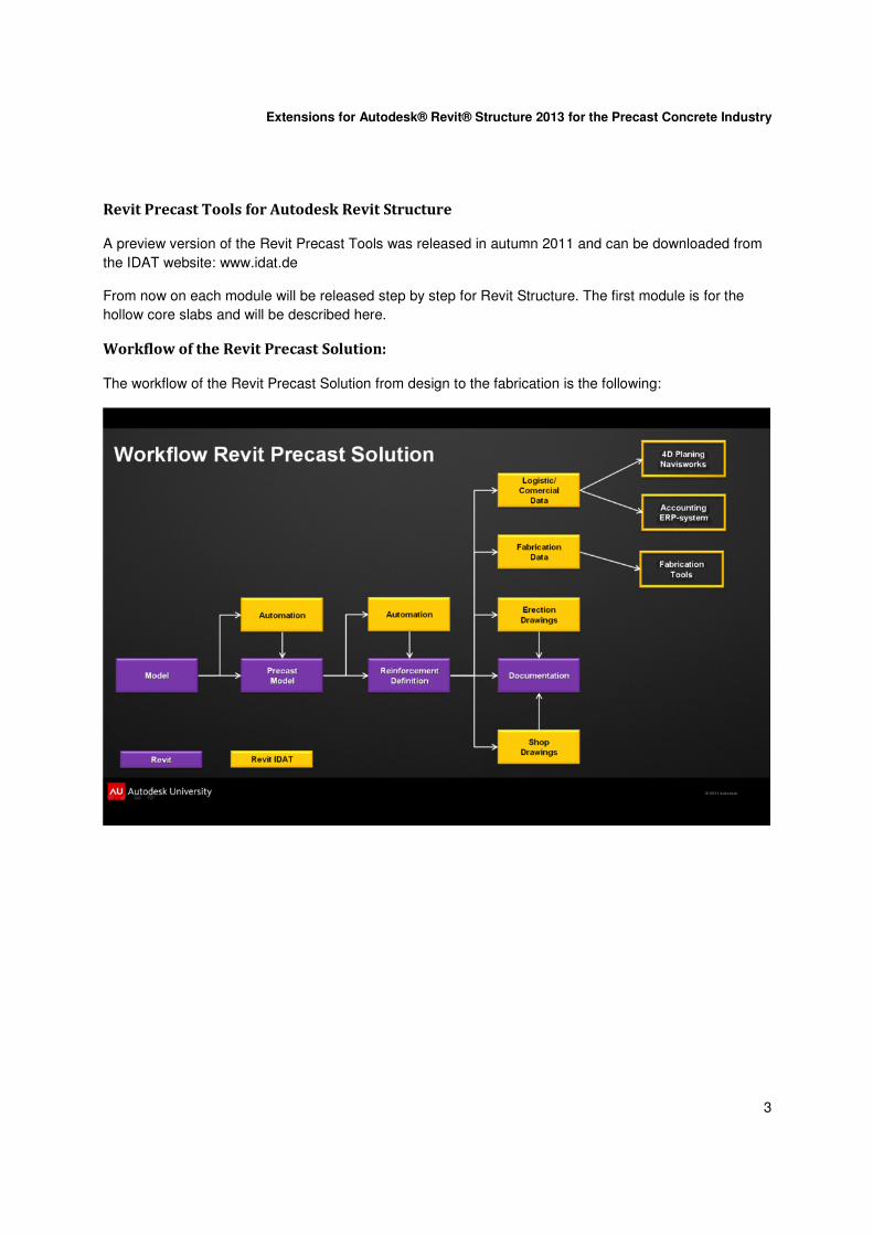
Workflow of the Revit Precast Solution:
The workflow of the Revit Precast Solution from design to the fabrication is the following:

Extensions for Autodesk® Revit® Structure 2013 for the Precast Concrete Industry
4
2. Creation of hollow core families For each hollow core type an own family must be defined. Within the family the section, the side profile
and the strand patterns are defined.
For the definition of the families some shared parameters are needed. These parameters must be load
from the shared parameters file ItSharedParameter.txt. This file is located in the program install folder e.g.
C:\ProgramData\IDAT\Revit Precast Tools 2013\.
Hole definition
For defining the holes of the elements you must start with the following template:
Metric Generic Model face based.rft
First create in the front view a reference plan and select Defines Origin:

Extensions for Autodesk® Revit® Structure 2013 for the Precast Concrete Industry
5
Now draw in the center an extrusion which represents the hole and dimension the center of the hole to
the top of the element. For the label of the dimension line choose “add parameter” and choose the shared
parameter “Position from Top” from the parameter group “IDAT GmbH”:
After ending the definition of the extrusion mark it as a void:
After that go to the Floor Plan view and dimension the length of the extrusion. For the label of the
dimension line choose the shared parameter “Element Length”.

Extensions for Autodesk® Revit® Structure 2013 for the Precast Concrete Industry
6
In the properties of the family set the two options “Cut with Voids When Loaded” and “Shared”:
The family must be stored in the program data folder e.g. C:\ProgramData\IDAT\Revit Precast Tools
2013\IDATFamilies\en-US\Hollow Core Slab.

Extensions for Autodesk® Revit® Structure 2013 for the Precast Concrete Industry
7
Side Profile
The profile on the left and right side of the panels must be defined in an own family. The template for this
family must be:
Metric Division Profile.rft
Draw on the left side lines which represents the side profile of the elements. The start and end of the lines
must be on the upper and lower reference plane.
The family must be stored in the program data folder e.g. C:\ProgramData\IDAT\Revit Precast Tools
2013\IDATFamilies\en-US\Profiles.
Cross section
For defining the cross section of the element you must start with the following template:
Metric Generic Model.rft
First create in the front view an extrusion with the width and height of the hollow core element:
Load now the hole family into this family and place one hole in the 3D-view inside of the element. After
that switch to the front view and place and copy all the holes on the right position. The position in vertical
direction can be set with the parameter “Position from Top” in the Type Properties of the hole.

Extensions for Autodesk® Revit® Structure 2013 for the Precast Concrete Industry
8
The side profile of the hollow core elements must be defined as a parameter. Therefore add the shared
parameter “ProfileType” and give as value the name of the family which you defined for the side profile.
The regions where the hollow core elements can be sawn in the factory (typically where no strands are)
must be defined. This must be done with the shared parameter “Valid widths”. The regions are defined
from left in the format [xxx-yyy] where xxx is start and yyy is the end of the region where the slab can be
cut.
Example:
[120-180][330-370][520-580][730-770][920-980][1130-1170]
After that save the family with the name hbd_xx.rfa were xx is the thickness of the slab. If you segment a
floor with the structural thickness xx the program searches for a family hbd_xx.rfa.
The family must be stored in the program data folder e.g. C:\ProgramData\IDAT\Revit Precast Tools
2013\IDATFamilies\en-US\Hollow Core Slab.
Strand pattern
With the strand pattern family the exact location of the strands can be defined. The easiest way to do this
is to open the family with the cross section and save it with the name hbd_xx_yyyy.rfa where xx is the
thickness of the slabs and yyyy is a name for the strand pattern. For one section family several strand
pattern families can be defined. All strand pattern families for a given section will be listed in a combo box
at the start of the segmentation.
To define the strands switch to the front view and create cylindrical extrusions with the diameter of the
strands at their exact location.

Extensions for Autodesk® Revit® Structure 2013 for the Precast Concrete Industry
9
After that delete the holes and the two defined parameters.
The family must be stored in the program data folder e.g. C:\ProgramData\IDAT\Revit Precast Tools
2013\IDATFamilies\en-US\Hollow Core Slab.
Title block family
The following shared parameter from the IDAT shared parameter file (C:\ProgramData\IDAT\Revit
Precast Tools 2013\ItSharedParameter.txt) can be used in the title block family:
Parameter Name Description
PosNoSheet The position number of the hollow core element
NumberElements Number of same elements with one position number
ListOfProduction Each element has a unique production number. This number will be used in external programs like the database and the UNITECHNIK file. This parameter gives a list of production numbers for one position.
FloortypeSheet The name of the hollow core type
ThicknessSheet The thickness of the hollow core element
WeightSheet The weight of the hollow core element
VolumeSheet The volume of the hollow core element

Extensions for Autodesk® Revit® Structure 2013 for the Precast Concrete Industry
10
3. Segmentation
A floor can be divided into hollow core slab elements. Therefor it is important that the span direction in the
floor is defined correct:
If you edit the boundary of the floor you can chose the span direction with the marked command:

Extensions for Autodesk® Revit® Structure 2013 for the Precast Concrete Industry
11
In the type properties of the floor there must exist a structural layer with a structural material:
For the thickness of the structural layer a hollow core family with this thickness must be defined. If this
preconditions are given you can use the splitting command from the IDAT Ribbon bar:
If no hollow core family with the thickness of the selected slab exists the following dialog with the
selection of the strands type is empty:

Extensions for Autodesk® Revit® Structure 2013 for the Precast Concrete Industry
12
If a valid hollow core family exists you can choose the strands type:
After that the segmentation starts. The program converts the selected floor into a part and divides the part
into parts with the width of the hollow core family. After the segmentation the program adds the holes and
the strands to the parts and converts all together to an assembly.
If the last element has not a full width, it must be cut. If the cut is in an area where it is not allowed to cut
(valid cuts are defined inside of the family) the following warning will be given:
The result will be shown in the structural plan view where the position number of the elements can be
seen. Same elements will get the same position number:

Extensions for Autodesk® Revit® Structure 2013 for the Precast Concrete Industry
13
In this view also the shifting direction is shown:
The program starts during the segmentation with the first element and puts the next elements in shifting
direction. The shifting direction can be changed by clicking the control arrows
If the last element has not the standard width, it must be cut. The side where the element must be cut in
the factory is marked with a saw symbol:
The side of the saw cut can also be changed with clicking the control arrows of the cut symbol.

Extensions for Autodesk® Revit® Structure 2013 for the Precast Concrete Industry
14
4. Assemblies Each hollow core element is converted to an assembly. During the creation of the assembly the system
checks which assemblies are the same and gives them the same assembly type name. In the data of the
assembly the strands type is stored and can be changed if needed:
Extensions for Autodesk® Revit® Structure 2013 for the Precast Concrete Industry
15
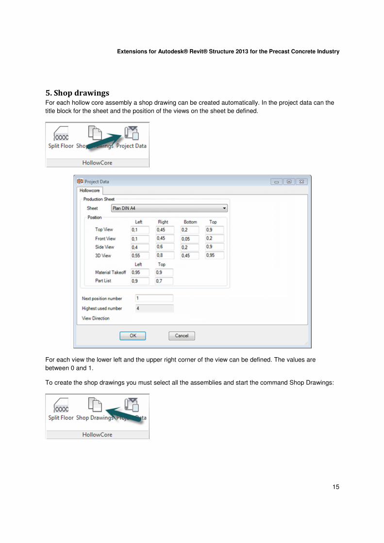
5. Shop drawings For each hollow core assembly a shop drawing can be created automatically. In the project data can the
title block for the sheet and the position of the views on the sheet be defined.
For each view the lower left and the upper right corner of the view can be defined. The values are
between 0 and 1.
To create the shop drawings you must select all the assemblies and start the command Shop Drawings:

Extensions for Autodesk® Revit® Structure 2013 for the Precast Concrete Industry
16
If no valid title block is set in the project dialog, the following error message will appear:
The created shop drawings can be found in the project browser of Revit under Assemblies.
Extensions for Autodesk® Revit® Structure 2013 for the Precast Concrete Industry
17
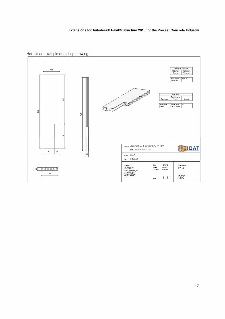
Here is an example of a shop drawing:

Extensions for Autodesk® Revit® Structure 2013 for the Precast Concrete Industry
18
6. Creating data for external programs
Data for external database
Call the command Database:
The data for all assemblies in the project will be written to an external database. This contains the geometric data, all the mounting parts and the reinforcement. Lists can be created out of this data or they can be exported to other programs like ERP systems.

Extensions for Autodesk® Revit® Structure 2013 for the Precast Concrete Industry
19
Machine files for the Stacker program
Select one or more hollow core assemblies and call the command UNITECHNIK:
For each selected wall assembly a UNITECHNIK file will be created. The UNITECHNIK file format is a
well know format in the Precast Concrete Industry. With this file all the needed information like the
geometry, the concrete, the mounting parts and the reinforcement are transferred to the factory for an
automated production.
This file can also be used to define the transport stacks with the Stacker program:
Extensions for Autodesk® Revit® Structure 2013 for the Precast Concrete Industry
20
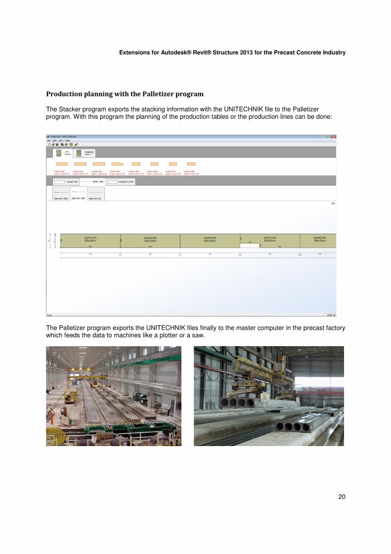
Production planning with the Palletizer program
The Stacker program exports the stacking information with the UNITECHNIK file to the Palletizer program. With this program the planning of the production tables or the production lines can be done:
The Palletizer program exports the UNITECHNIK files finally to the master computer in the precast factory which feeds the data to machines like a plotter or a saw.

Extensions for Autodesk® Revit® Structure 2013 for the Precast Concrete Industry
21
Change to the model
If there is a change in the Revit model after all the machine files are created only the UNITECHNIK files for the according assemblies must be created again.
Summary:
The module Hollow Core Slabs of the Revit Precast Tools supports the Precast Concrete Industry in the
following areas:
� Automatic segmentation
� Creation of hollow core elements with correct sections and strand patterns
� Converting to assemblies with equality check
� Creation of shop drawings
� Exporting data to external programs
� Changes in the model
� Production
The Revit Precast Tools supports and speeds up the full workflow from design to fabrication for Precast
Elements inside of Revit
A preview version of the Revit Precast Tools can be downloaded: www.idat.de