extending e-business to pervasive computing … mryhij muhammed ... 2.6.4 uninstall and secureway...
TRANSCRIPT

ibm.com/redbooks
Extending e-business to Pervasive Computing DevicesUsing WebSphere Everyplace Suite Version 1.1.2
Juan R. RodriguezJose L. Jacob
Amir MryhijMuhammed Omarjee
Amy PattonHao Wang
Learn about overall WebSphere Everyplace Suite architecture
Understand WebSphere Everyplace Suite integration
Identify the basic steps for planning a deployment


International Technical Support Organization SG24-5996-00
Extending e-business to Pervasive Computing DevicesUsing WebSphere Everyplace Suite Version 1.1.2
April 2001

© Copyright International Business Machines Corporation 2001. All rights reserved.Note to U.S Government Users - Documentation related to restricted rights - Use, duplication or disclosure is subject to restrictionsset forth in GSA ADP Schedule Contract with IBM Corp.
First Edition (April 2001)
This edition applies to Version 1.1.2 of IBM WebSphere Everyplace Suite for use with the AIX and Sun Solaris operating systems.
Comments may be addressed to:IBM Corporation, International Technical Support OrganizationDept. HZ8 Building 662P.O. Box 12195Research Triangle Park, NC 27709-2195
When you send information to IBM, you grant IBM a non-exclusive right to use or distribute the information in any way it believes appropriate without incurring any obligation to you.
Before using this information and the product it supports, be sure to read the general information in Appendix A, “Special notices” on page 261.
Take Note!
Contents
Preface . . . . . . . . . . . . . . . . . . . . . . . . . . . . . . . . . . . . . . . . . . . . . . . . . . . . . . viiThe team that wrote this redbook . . . . . . . . . . . . . . . . . . . . . . . . . . . . . . . . . . . . . . viiComments welcome . . . . . . . . . . . . . . . . . . . . . . . . . . . . . . . . . . . . . . . . . . . . . . . . viii
Chapter 1. Overview . . . . . . . . . . . . . . . . . . . . . . . . . . . . . . . . . . . . . . . . . . . .11.1 Introduction . . . . . . . . . . . . . . . . . . . . . . . . . . . . . . . . . . . . . . . . . . . . . . . . .1
1.1.1 WAP . . . . . . . . . . . . . . . . . . . . . . . . . . . . . . . . . . . . . . . . . . . . . . . . . .31.1.2 Wireless Internet . . . . . . . . . . . . . . . . . . . . . . . . . . . . . . . . . . . . . . . . .31.1.3 Home automation products . . . . . . . . . . . . . . . . . . . . . . . . . . . . . . . . .31.1.4 Meeting the challenges . . . . . . . . . . . . . . . . . . . . . . . . . . . . . . . . . . . .4
1.2 Pervasive computing requirements . . . . . . . . . . . . . . . . . . . . . . . . . . . . . . .41.2.1 Extending e-business to pervasive computing devices . . . . . . . . . . . .4
1.3 IBM WebSphere Everyplace Suite overview . . . . . . . . . . . . . . . . . . . . . . . .61.3.1 WES implementation . . . . . . . . . . . . . . . . . . . . . . . . . . . . . . . . . . . . . .7
1.4 WES scenario . . . . . . . . . . . . . . . . . . . . . . . . . . . . . . . . . . . . . . . . . . . . . .101.5 WES Authentication Server . . . . . . . . . . . . . . . . . . . . . . . . . . . . . . . . . . . .111.6 Everyplace Wireless Gateway . . . . . . . . . . . . . . . . . . . . . . . . . . . . . . . . . .141.7 IBM WebSphere Transcoding Publisher . . . . . . . . . . . . . . . . . . . . . . . . . .161.8 WebSphere Edge Server . . . . . . . . . . . . . . . . . . . . . . . . . . . . . . . . . . . . .19
1.8.1 Edge Server - Caching Proxy . . . . . . . . . . . . . . . . . . . . . . . . . . . . . .201.8.2 Edge Server - Load Balancer . . . . . . . . . . . . . . . . . . . . . . . . . . . . . .20
1.9 Subscriber and Device Management Services . . . . . . . . . . . . . . . . . . . . .211.9.1 Subscriber Management Services . . . . . . . . . . . . . . . . . . . . . . . . . . .22
1.10 MQSeries Everyplace . . . . . . . . . . . . . . . . . . . . . . . . . . . . . . . . . . . . . . .241.11 Data Synchronization Manager . . . . . . . . . . . . . . . . . . . . . . . . . . . . . . . .251.12 Other software included in WES . . . . . . . . . . . . . . . . . . . . . . . . . . . . . . .27
Chapter 2. Installation guidelines . . . . . . . . . . . . . . . . . . . . . . . . . . . . . . . .292.1 WebSphere Everyplace Suite 1.1.2 functional content . . . . . . . . . . . . . . .292.2 Everyplace component prerequisites. . . . . . . . . . . . . . . . . . . . . . . . . . . . .30
2.2.1 WES CD-ROM contents . . . . . . . . . . . . . . . . . . . . . . . . . . . . . . . . . .312.3 WES installation overview . . . . . . . . . . . . . . . . . . . . . . . . . . . . . . . . . . . . .312.4 Supporting WES installation . . . . . . . . . . . . . . . . . . . . . . . . . . . . . . . . . . .34
2.4.1 Information sharing and cross component communications . . . . . . . .342.5 WES installation process . . . . . . . . . . . . . . . . . . . . . . . . . . . . . . . . . . . . .38
2.5.1 Create and Retrieve from LDIF file . . . . . . . . . . . . . . . . . . . . . . . . . .612.5.2 Troubleshooting . . . . . . . . . . . . . . . . . . . . . . . . . . . . . . . . . . . . . . . .612.5.3 Validation procedure . . . . . . . . . . . . . . . . . . . . . . . . . . . . . . . . . . . . .62
2.6 Uninstall . . . . . . . . . . . . . . . . . . . . . . . . . . . . . . . . . . . . . . . . . . . . . . . . . .622.6.1 Starting the uninstall program . . . . . . . . . . . . . . . . . . . . . . . . . . . . . .622.6.2 Selecting and uninstalling components . . . . . . . . . . . . . . . . . . . . . . .622.6.3 DB2 and its database removal. . . . . . . . . . . . . . . . . . . . . . . . . . . . . .632.6.4 Uninstall and SecureWay Directory (LDAP). . . . . . . . . . . . . . . . . . . .64
Chapter 3. Administration Console . . . . . . . . . . . . . . . . . . . . . . . . . . . . . . .653.1 Overview. . . . . . . . . . . . . . . . . . . . . . . . . . . . . . . . . . . . . . . . . . . . . . . . . .65
3.1.1 Functionality . . . . . . . . . . . . . . . . . . . . . . . . . . . . . . . . . . . . . . . . . . .653.1.2 Starting the Administration Console . . . . . . . . . . . . . . . . . . . . . . . . .66
3.2 Launching a component’s Administration Console . . . . . . . . . . . . . . . . . .683.3 Port numbers . . . . . . . . . . . . . . . . . . . . . . . . . . . . . . . . . . . . . . . . . . . . . .69
3.3.1 Changing port numbers . . . . . . . . . . . . . . . . . . . . . . . . . . . . . . . . . . .69
© Copyright IBM Corp. 2001 iii

Chapter 4. WebSphere Everyplace Suite sample scenario . . . . . . . . . . . . 714.1 Overview . . . . . . . . . . . . . . . . . . . . . . . . . . . . . . . . . . . . . . . . . . . . . . . . . 71
4.1.1 Scope . . . . . . . . . . . . . . . . . . . . . . . . . . . . . . . . . . . . . . . . . . . . . . . 714.1.2 Description . . . . . . . . . . . . . . . . . . . . . . . . . . . . . . . . . . . . . . . . . . . 714.1.3 Wireless application design . . . . . . . . . . . . . . . . . . . . . . . . . . . . . . . 72
4.2 The solution. . . . . . . . . . . . . . . . . . . . . . . . . . . . . . . . . . . . . . . . . . . . . . . 734.3 Topology and component implementation . . . . . . . . . . . . . . . . . . . . . . . . 754.4 Sample Scenario code. . . . . . . . . . . . . . . . . . . . . . . . . . . . . . . . . . . . . . . 77
4.4.1 Sample XMLs . . . . . . . . . . . . . . . . . . . . . . . . . . . . . . . . . . . . . . . . . 774.4.2 Style sheets (XSLs) . . . . . . . . . . . . . . . . . . . . . . . . . . . . . . . . . . . . . 784.4.3 WML wes1.wml starting page for the Nokia Emulator. . . . . . . . . . . . 844.4.4 ServeXML_news.java Servlet . . . . . . . . . . . . . . . . . . . . . . . . . . . . . 844.4.5 HelloWorldServlet.java. . . . . . . . . . . . . . . . . . . . . . . . . . . . . . . . . . . 854.4.6 Default index.htm. . . . . . . . . . . . . . . . . . . . . . . . . . . . . . . . . . . . . . . 86
Chapter 5. End-user enrollment . . . . . . . . . . . . . . . . . . . . . . . . . . . . . . . . . 895.1 Overview . . . . . . . . . . . . . . . . . . . . . . . . . . . . . . . . . . . . . . . . . . . . . . . . . 895.2 Enrollment and service provisioning . . . . . . . . . . . . . . . . . . . . . . . . . . . . 90
5.2.1 Subscriber registration . . . . . . . . . . . . . . . . . . . . . . . . . . . . . . . . . . . 915.2.2 Business account options . . . . . . . . . . . . . . . . . . . . . . . . . . . . . . . . 915.2.3 Multiple enrollment channels . . . . . . . . . . . . . . . . . . . . . . . . . . . . . . 92
5.3 Customer care services . . . . . . . . . . . . . . . . . . . . . . . . . . . . . . . . . . . . . . 935.4 Device Manager . . . . . . . . . . . . . . . . . . . . . . . . . . . . . . . . . . . . . . . . . . . 945.5 Enrollment: a sample scenario. . . . . . . . . . . . . . . . . . . . . . . . . . . . . . . . . 95
5.5.1 Web-based enrollment . . . . . . . . . . . . . . . . . . . . . . . . . . . . . . . . . . . 975.5.2 LDAP . . . . . . . . . . . . . . . . . . . . . . . . . . . . . . . . . . . . . . . . . . . . . . . 1045.5.3 Banner ad enrollment. . . . . . . . . . . . . . . . . . . . . . . . . . . . . . . . . . . 104
Chapter 6. User authentication . . . . . . . . . . . . . . . . . . . . . . . . . . . . . . . . . 1096.1 Overview . . . . . . . . . . . . . . . . . . . . . . . . . . . . . . . . . . . . . . . . . . . . . . . . 109
6.1.1 Everyplace Authentication Server modes. . . . . . . . . . . . . . . . . . . . 1106.1.2 HTTP access authentication framework . . . . . . . . . . . . . . . . . . . . . 1106.1.3 Basic access authentication. . . . . . . . . . . . . . . . . . . . . . . . . . . . . . 1116.1.4 Security considerations . . . . . . . . . . . . . . . . . . . . . . . . . . . . . . . . . 1116.1.5 How reverse proxy works. . . . . . . . . . . . . . . . . . . . . . . . . . . . . . . . 1126.1.6 Configuration . . . . . . . . . . . . . . . . . . . . . . . . . . . . . . . . . . . . . . . . . 112
6.2 Sample scenario: Authentication Proxy (AP) . . . . . . . . . . . . . . . . . . . . . 1136.2.1 Authentication Proxy (AP) . . . . . . . . . . . . . . . . . . . . . . . . . . . . . . . 1136.2.2 Authentication Proxy (AP) configuration. . . . . . . . . . . . . . . . . . . . . 1146.2.3 Securing AP connections . . . . . . . . . . . . . . . . . . . . . . . . . . . . . . . . 1186.2.4 Running the scenario . . . . . . . . . . . . . . . . . . . . . . . . . . . . . . . . . . . 118
6.3 Sample scenario: Transparent Authentication Proxy (TP) . . . . . . . . . . . 1216.3.1 Transparent Proxy (TP) . . . . . . . . . . . . . . . . . . . . . . . . . . . . . . . . . 1226.3.2 Transparent Proxy (TP) configuration . . . . . . . . . . . . . . . . . . . . . . 1236.3.3 Client configuration . . . . . . . . . . . . . . . . . . . . . . . . . . . . . . . . . . . . 1266.3.4 Running the scenario . . . . . . . . . . . . . . . . . . . . . . . . . . . . . . . . . . . 126
Chapter 7. Transcoding . . . . . . . . . . . . . . . . . . . . . . . . . . . . . . . . . . . . . . . 1297.1 Overview . . . . . . . . . . . . . . . . . . . . . . . . . . . . . . . . . . . . . . . . . . . . . . . . 1297.2 Basic flow for Transcoding Publisher acting as a proxy . . . . . . . . . . . . . 1307.3 WES Authentication Server and Transcoding . . . . . . . . . . . . . . . . . . . . 1317.4 Configuration . . . . . . . . . . . . . . . . . . . . . . . . . . . . . . . . . . . . . . . . . . . . . 132
7.4.1 Port mapping . . . . . . . . . . . . . . . . . . . . . . . . . . . . . . . . . . . . . . . . . 1327.4.2 Using a caching proxy . . . . . . . . . . . . . . . . . . . . . . . . . . . . . . . . . . 133
iv Extending e-business to Pervasive Computing Devices Using IBM WebSphere Everyplace Suite V1.1.2

7.4.3 Firewall configuration . . . . . . . . . . . . . . . . . . . . . . . . . . . . . . . . . . .1337.5 Transcoding tools . . . . . . . . . . . . . . . . . . . . . . . . . . . . . . . . . . . . . . . . . .134
7.5.1 Request Viewer. . . . . . . . . . . . . . . . . . . . . . . . . . . . . . . . . . . . . . . .1347.5.2 The Transform Tool. . . . . . . . . . . . . . . . . . . . . . . . . . . . . . . . . . . . .1407.5.3 Using XML style sheets with the Transform Tool . . . . . . . . . . . . . . .144
7.6 Sample scenario . . . . . . . . . . . . . . . . . . . . . . . . . . . . . . . . . . . . . . . . . . .1457.6.1 Proxy configuration in the Authentication Server . . . . . . . . . . . . . . .1467.6.2 Using the WTP Administration Console . . . . . . . . . . . . . . . . . . . . . .1467.6.3 Running the WAS application from a Web browser . . . . . . . . . . . . .1537.6.4 Running the application from a WAP simulator . . . . . . . . . . . . . . . .156
Chapter 8. Caching transcoded pages . . . . . . . . . . . . . . . . . . . . . . . . . . .1618.1 Overview. . . . . . . . . . . . . . . . . . . . . . . . . . . . . . . . . . . . . . . . . . . . . . . . .161
8.1.1 Relationship to external cache . . . . . . . . . . . . . . . . . . . . . . . . . . . .1618.1.2 Understanding caching . . . . . . . . . . . . . . . . . . . . . . . . . . . . . . . . . .162
8.2 Configuration . . . . . . . . . . . . . . . . . . . . . . . . . . . . . . . . . . . . . . . . . . . . .1648.2.1 Considerations for configuring the external cache . . . . . . . . . . . . . .1668.2.2 When is caching beneficial? . . . . . . . . . . . . . . . . . . . . . . . . . . . . . .1668.2.3 Web Traffic Express (WTE) configuration . . . . . . . . . . . . . . . . . . . .1678.2.4 Tuning cache server . . . . . . . . . . . . . . . . . . . . . . . . . . . . . . . . . . . .167
8.3 Troubleshooting . . . . . . . . . . . . . . . . . . . . . . . . . . . . . . . . . . . . . . . . . . .167
Chapter 9. Wireless Gateway . . . . . . . . . . . . . . . . . . . . . . . . . . . . . . . . . . .1719.1 Introduction . . . . . . . . . . . . . . . . . . . . . . . . . . . . . . . . . . . . . . . . . . . . . . .1719.2 Overview. . . . . . . . . . . . . . . . . . . . . . . . . . . . . . . . . . . . . . . . . . . . . . . . .171
9.2.1 Supported features . . . . . . . . . . . . . . . . . . . . . . . . . . . . . . . . . . . . .1729.2.2 Optimization techniques . . . . . . . . . . . . . . . . . . . . . . . . . . . . . . . . .174
9.3 Deployment of the Everyplace Wireless Gateway . . . . . . . . . . . . . . . . . .1759.3.1 Delivery enterprise . . . . . . . . . . . . . . . . . . . . . . . . . . . . . . . . . . . . .1769.3.2 Internet Service Provider (ISP) . . . . . . . . . . . . . . . . . . . . . . . . . . . .1779.3.3 Content provider . . . . . . . . . . . . . . . . . . . . . . . . . . . . . . . . . . . . . . .177
9.4 Install Everyplace Wireless Gateway. . . . . . . . . . . . . . . . . . . . . . . . . . . .1789.5 Basic configuration . . . . . . . . . . . . . . . . . . . . . . . . . . . . . . . . . . . . . . . . .1829.6 WAP Gateway configuration . . . . . . . . . . . . . . . . . . . . . . . . . . . . . . . . . .1909.7 Wireless Gateway Clustering . . . . . . . . . . . . . . . . . . . . . . . . . . . . . . . . .195
9.7.1 Cluster Manager (CM) . . . . . . . . . . . . . . . . . . . . . . . . . . . . . . . . . . .1969.8 Gateway security scenarios . . . . . . . . . . . . . . . . . . . . . . . . . . . . . . . . . .1989.9 A sample WAP scenario . . . . . . . . . . . . . . . . . . . . . . . . . . . . . . . . . . . . .202
Chapter 10. Wireless Gateway administration . . . . . . . . . . . . . . . . . . . . .20710.1 Why a Gatekeeper? What does it solve?. . . . . . . . . . . . . . . . . . . . . . . .20710.2 Terms to be familiar with . . . . . . . . . . . . . . . . . . . . . . . . . . . . . . . . . . . .20710.3 Gatekeeper security tips . . . . . . . . . . . . . . . . . . . . . . . . . . . . . . . . . . . .208
10.3.1 Gatekeeper-to-Gateway communication . . . . . . . . . . . . . . . . . . . .20810.3.2 Encryption . . . . . . . . . . . . . . . . . . . . . . . . . . . . . . . . . . . . . . . . . . .20910.3.3 Administrator’s password . . . . . . . . . . . . . . . . . . . . . . . . . . . . . . .20910.3.4 User management tips . . . . . . . . . . . . . . . . . . . . . . . . . . . . . . . . .209
10.4 Installing the Gatekeeper - initial configuration tips . . . . . . . . . . . . . . . .20910.5 Configuring resources . . . . . . . . . . . . . . . . . . . . . . . . . . . . . . . . . . . . . .21010.6 Sample configurations. . . . . . . . . . . . . . . . . . . . . . . . . . . . . . . . . . . . . .211
10.6.1 Creating an MNI . . . . . . . . . . . . . . . . . . . . . . . . . . . . . . . . . . . . . .21110.6.2 Creating an administrator . . . . . . . . . . . . . . . . . . . . . . . . . . . . . . .21410.6.3 Setting up an ACL . . . . . . . . . . . . . . . . . . . . . . . . . . . . . . . . . . . . .216
10.7 Troubleshooting tips . . . . . . . . . . . . . . . . . . . . . . . . . . . . . . . . . . . . . . .218
v

10.8 Need more help? . . . . . . . . . . . . . . . . . . . . . . . . . . . . . . . . . . . . . . . . . 21910.9 Sample WAP Gateway configuration . . . . . . . . . . . . . . . . . . . . . . . . . . 219
Chapter 11. Secure Sockets Layer (SSL) . . . . . . . . . . . . . . . . . . . . . . . . . 22511.1 Overview . . . . . . . . . . . . . . . . . . . . . . . . . . . . . . . . . . . . . . . . . . . . . . . 225
11.1.1 Symmetric cryptography versus asymmetric cryptography . . . . . . 22511.1.2 Digital certificate . . . . . . . . . . . . . . . . . . . . . . . . . . . . . . . . . . . . . 22711.1.3 Certificate Authority (CA) . . . . . . . . . . . . . . . . . . . . . . . . . . . . . . . 22711.1.4 Trusted root . . . . . . . . . . . . . . . . . . . . . . . . . . . . . . . . . . . . . . . . . 22811.1.5 Certificate Revocation List (CRL) . . . . . . . . . . . . . . . . . . . . . . . . . 22811.1.6 Digital signature . . . . . . . . . . . . . . . . . . . . . . . . . . . . . . . . . . . . . . 22811.1.7 Public Key Infrastructure (PKI) . . . . . . . . . . . . . . . . . . . . . . . . . . . 22911.1.8 Security methods and standards . . . . . . . . . . . . . . . . . . . . . . . . . 22911.1.9 SSL tunneling . . . . . . . . . . . . . . . . . . . . . . . . . . . . . . . . . . . . . . . 231
11.2 Secure connections . . . . . . . . . . . . . . . . . . . . . . . . . . . . . . . . . . . . . . . 23211.3 Steps to establish SSL server authentication . . . . . . . . . . . . . . . . . . . . 234
11.3.1 Obtaining a digital certificate . . . . . . . . . . . . . . . . . . . . . . . . . . . . 23411.3.2 Configuring SSL. . . . . . . . . . . . . . . . . . . . . . . . . . . . . . . . . . . . . . 241
11.4 SSL Client authentication . . . . . . . . . . . . . . . . . . . . . . . . . . . . . . . . . . 24711.5 Configuring the browser to add a new trusted root . . . . . . . . . . . . . . . . 248
11.5.1 Using a self-signed certificate . . . . . . . . . . . . . . . . . . . . . . . . . . . 24911.5.2 Using a VeriSign free trial certificate . . . . . . . . . . . . . . . . . . . . . . 250
Chapter 12. Wireless Transport Layer Security (WTLS) . . . . . . . . . . . . . 25112.1 Why WTLS? . . . . . . . . . . . . . . . . . . . . . . . . . . . . . . . . . . . . . . . . . . . . 251
12.1.1 Principles of WTLS . . . . . . . . . . . . . . . . . . . . . . . . . . . . . . . . . . . 25112.2 WTLS implementation in IBM WebSphere Everyplace Suite . . . . . . . . 255
12.2.1 Steps to establish WTLS server authentication . . . . . . . . . . . . . . 255
Appendix A. Special notices . . . . . . . . . . . . . . . . . . . . . . . . . . . . . . . . . . . . . .261
Appendix B. Related publications . . . . . . . . . . . . . . . . . . . . . . . . . . . . . . . . .263B.1 IBM Redbooks . . . . . . . . . . . . . . . . . . . . . . . . . . . . . . . . . . . . . . . . . . . . . . . .263B.2 IBM Redbooks collections . . . . . . . . . . . . . . . . . . . . . . . . . . . . . . . . . . . . . . .263B.3 Other resources . . . . . . . . . . . . . . . . . . . . . . . . . . . . . . . . . . . . . . . . . . . . . . .263B.4 Referenced Web sites . . . . . . . . . . . . . . . . . . . . . . . . . . . . . . . . . . . . . . . . . .264
How to get IBM Redbooks . . . . . . . . . . . . . . . . . . . . . . . . . . . . . . . . . . . . . 267IBM Redbooks fax order form . . . . . . . . . . . . . . . . . . . . . . . . . . . . . . . . . . . . . . . .268
Glossary . . . . . . . . . . . . . . . . . . . . . . . . . . . . . . . . . . . . . . . . . . . . . . . . . . . 269
Index . . . . . . . . . . . . . . . . . . . . . . . . . . . . . . . . . . . . . . . . . . . . . . . . . . . . . . 273
IBM Redbooks review . . . . . . . . . . . . . . . . . . . . . . . . . . . . . . . . . . . . . . . . . 277
vi Extending e-business to Pervasive Computing Devices Using IBM WebSphere Everyplace Suite V1.1.2

Preface
IBM WebSphere Everyplace Suite Version 1.1.2 is an integrated, end-to-end software solution for mobile e-business. This redbook is about deploying this product to enable Web and enterprise application access from pervasive computing devices. This redbook helps you to understand the requirements of this product and focuses on how Everyplace Suite components fit together. You will find information on the implemented functionality such as user enrollment, end-user authentication, transcoding, wireless communications, and security, among other topics.
The information included in this redbook will help you plan to successfully implement solutions that businesses must address to be able to access Web and enterprise applications from desktop browsers and the new class of client devices such as WAP phones, Palm Pilots, WorkPads, and others.
A basic knowledge of HTTP and WAP protocols as well as some understanding of Web and Java technologies (XML, HTML, WML, servlets, and JSPs) and the terminology used in Web and enterprise applications is assumed.
The team that wrote this redbook
This redbook was produced by a team of specialists from around the world working at the International Technical Support Organization, Raleigh Center.
Juan R. Rodriguez is a consulting IT professional at the IBM ITSO Center, Raleigh. He received his M.S. degree in Computer Science from Iowa State University. He writes extensively and teaches IBM classes worldwide on such topics as networking, Web technologies and data security. Before joining the IBM ITSO, he worked at the IBM laboratory in Research Triangle Park (North Carolina, USA) as a designer and developer of networking products.
Jose L. Jacob is an Information Technology Specialist in IBM Canada. He specializes in system management, including Tivoli products. He holds a degree in Engineering and has 28 years of experience with IBM, which includes the development of finance industry systems at the IBM Toronto Laboratory and consulting on the implementation of system management solutions for the banking industry.
Hao Wang is a senior executive of Deuk Company, a technology and management consulting firm based in Cambridge, Massachusetts. He has a Ph.D. in optoelectronics from Massachusetts Institute of Technology (MIT) and an MPA degree from Harvard University. Hao is the founder of Deuk Company and Noah.Net, Inc., a wireless application service provider (ASP) enabling business-to-business and business-to-consumer pervasive computing. Hao has published many technical journal articles.
© Copyright IBM Corp. 2001 vii
Amir Mryhij is a principal consultant with more than 16 years of experience in the IT industry. He has participated as a Software Engineer, consultant, project manager, and chief architect in projects around the world. He holds a Master’s degree in Information Technology from the University of Western Sydney. He is IBM-certified as an e-business Designer and is Microsoft-certified for SQL server, Windows architecture, and Windows NT. He is the country consulting services manager for GBM Bahrain and Qatar.
Amy Patton is a technical developer at Immersant in Cambridge, Massachusetts. Amy specializes in Web applications development, from network and database design to Java user interfaces. Amy graduated from Boston University with a Bachelor of Arts in Computer Science.
Muhammed Omarjee is an IT specialist with IBM Business Innovation Services in Johannesburg, South Africa. He started with IBM as an applications software developer in e-business and Web-oriented solutions. His current area of expertise is centered around Web technologies such as Java, markup languages, and related object-oriented technologies. He holds a National Diploma in Information Technology from the Technikon Witwatersrand of South Africa.
Thanks to the following people for their invaluable contributions to this project:
Anthony Wrobel, CD Choi, Barbara Wetmore, George Hall, Henry Welborn, Samuel Camut, Pinwu Xu, Ronnie Jones, Salim Zeitouni, Allen LakeIBM Research Triangle Park, North Carolina, USA
Richard ApplebyIBM United Kingdom
Bernt BisgaardIBM Denmark
Adrienne McGroryIBM United Kingdom
Comments welcome
Your comments are important to us!
We want our Redbooks to be as helpful as possible. Please send us your comments about this or other Redbooks in one of the following ways:
• Fax the evaluation form found in “IBM Redbooks review” on page 277 to the fax number shown on the form.
• Use the online evaluation form found at ibm.com/redbooks
• Send your comments in an Internet note to [email protected]
viii Extending e-business to Pervasive Computing Devices Using IBM WebSphere Everyplace Suite V1.1.2

Chapter 1. Overview
IBM WebSphere Everyplace Suite is a comprehensive, integrated software platform for extending the reach of e-business applications, enterprise data, and Internet content into the realm of pervasive computing. In this chapter we introduce the features, functions and benefits of the IBM WebSphere Everyplace Suite (WES) product.
1.1 Introduction
If we look at the way we use computing today and think about the future we will find that new options are needed to satisfy customer requirements and to keep up with the way we do business nowadays. Users expect to use mobile phones to access Web applications. In addition, users expect to subscribe to services instead of buying products. Many access and portal service providers are evolving to provide a higher added value in services, such as e-commerce and application hosting. In fact, many software vendors are already providing software products as online subscription based services instead of PC-based applications. The whole industry is moving rapidly from proprietary connectivity to standard-based connectivity (for example, Wireless Application Protocol) and the fragmented development platform market is moving to share one consolidated framework.
Today, professionals are conducting an increasing number of business activities outside traditional office settings. These "mobile professionals" (see Figure 1) need tools and services that allow them to access and interact with information and services relevant to their enterprises. In this portable business climate, devices must work together seamlessly. In this environment, given the sensitive nature of business information, it is imperative that transactions must be conducted with the highest levels of security.
© Copyright IBM Corp. 2001 1

Figure 1. Pervasive computing (PvC) mobile e-business users
This means we are increasingly relying on the electronic creation, storage, and transmittal of personal, financial, and other confidential information. At thesame time, we demand the highest security for all these transactions. Also, we increasingly require complete access to time-sensitive data, regardless of its physical location. We expect devices, such as personal digital assistants, mobile phones, office PCs and home entertainment systems, to access that information and work together in one seamless, integrated system.
These new intelligent appliances or "smart devices" are embedded with microprocessors that allow users to plug into intelligent networks and gain direct, simple, and secure access to both relevant information and services. These devices are as simple to use as calculators, telephones, or kitchen toasters.
Pervasive computing technology aims to enable people to accomplish an increasing number of personal and professional transactions, using a new class of intelligent and portable devices. It gives people convenient access to relevant information stored on powerful networks, allowing them to easily take action anywhere and anytime, as illustrated in Figure 2.
2 Extending e-business to Pervasive Computing Devices Using IBM WebSphere Everyplace Suite V1.1.2
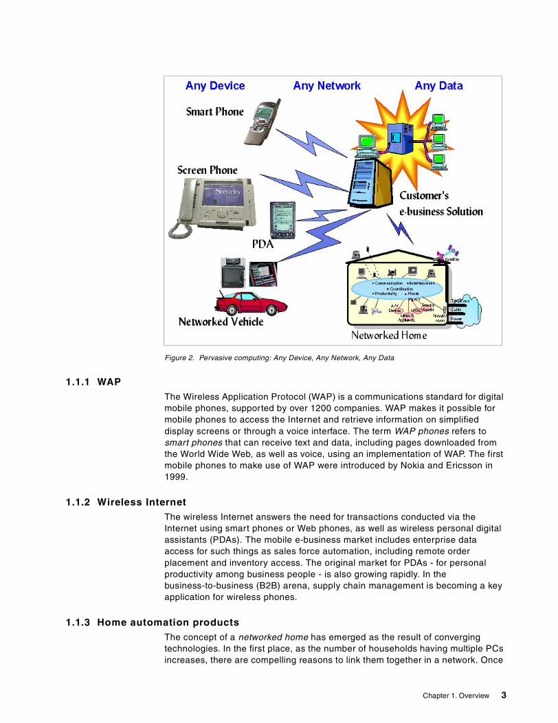
Figure 2. Pervasive computing: Any Device, Any Network, Any Data
1.1.1 WAPThe Wireless Application Protocol (WAP) is a communications standard for digital mobile phones, supported by over 1200 companies. WAP makes it possible for mobile phones to access the Internet and retrieve information on simplified display screens or through a voice interface. The term WAP phones refers to smart phones that can receive text and data, including pages downloaded from the World Wide Web, as well as voice, using an implementation of WAP. The first mobile phones to make use of WAP were introduced by Nokia and Ericsson in 1999.
1.1.2 Wireless InternetThe wireless Internet answers the need for transactions conducted via the Internet using smart phones or Web phones, as well as wireless personal digital assistants (PDAs). The mobile e-business market includes enterprise data access for such things as sales force automation, including remote order placement and inventory access. The original market for PDAs - for personal productivity among business people - is also growing rapidly. In the business-to-business (B2B) arena, supply chain management is becoming a key application for wireless phones.
1.1.3 Home automation productsThe concept of a networked home has emerged as the result of converging technologies. In the first place, as the number of households having multiple PCs increases, there are compelling reasons to link them together in a network. Once
Chapter 1. Overview 3

that is done, they can share peripherals as well as access to the Internet. When a household has established a common connection to the Internet, it becomes possible to add the convenience of remote control to many home automation functions, such as security systems, climate control, and so on. The Internet connection facilitates access to those controls from any computing device, such as your office computer or your Web phone. As functionality increases, the manufacturers and vendors of home automation products have an important role to play in the evolution of pervasive systems.
1.1.4 Meeting the challengesAs pervasive systems evolve, organizations are developing and implementing solutions for automation that address such complex requirements as the following:
• Leveraging existing e-business investments
• Supporting a wide variety of pervasive devices
• Adjusting for unique screen size, memory, and display capabilities of PvC devices
• Managing and supporting pervasive computing devices that are often used over mobile networks, such as dial-up and wireless networks, some of which have non-IP protocols (WAP, phone.com, Mobitex, etc.)
• Considering variations in speed, costs, and coverage
• Securing online or intermittently connected transactions
• Supporting pervasive computing application models (client/server, browser-based, etc.)
1.2 Pervasive computing requirements
Pervasive computing is about connecting a wide variety of client devices to a modern Web environment. These devices include:
• Personal digital assistants (PDAs) such as Palm and Windows CE • Cellular phones • Automotive computers • Home gateways • Wearable computers • Traditional PCs
It is also about enabling interaction and e-business to occur via technology that is virtually invisible to the end user.
This is accomplished by leveraging the IBM Application Framework for e-business and other proven Web technologies, such as WebSphere Application Server, DB2, MQSeries Everyplace, enterprise connectors, etc. to include support for PDAs and WAP phones, network independence and, more importantly, open standards.
1.2.1 Extending e-business to pervasive computing devicesWhen compared to e-business solutions that connect desktop PCs to servers, pervasive computing introduces the following unique requirements:
4 Extending e-business to Pervasive Computing Devices Using IBM WebSphere Everyplace Suite V1.1.2

• Generate and process different types of input/output content.
Some devices have only text capabilities, others also have graphical capabilities, and others may add or be limited to audio capabilities. The industry is separating content from presentation using XML. Pervasive middleware must be capable of generating and processing multiple types of markup languages such as subsets of HTML (HTML 3.2, CompactHTML) or other XML presentation languages (WML, VoiceXML).
• Customize content and distribution based on user, device, and network characteristics.
Content delivered to pervasive devices needs to be personalized, not only to reflect the user's content preferences (content selection and filtering), but also to reflect the environment (for example, to reduce content size to match network bandwidth or re-format content to match a particular target device). Simply selecting the right markup language is insufficient, because different pervasive devices will present the same content differently.
• Support asynchronous client-server messaging and data synchronization.
Pervasive devices, unlike desktop PCs, typically are not always connected to the network. Instead, they need to be able to queue outbound requests and asynchronously receive messages delivered from the network. Similarly, pervasive devices typically contain a local data store that can be modified offline and therefore must be synchronized with the primary data server.
• Enable alternative access protocols, such as the Wireless Application Protocol (WAP).
The pervasive device space is dominated by non-IP protocols that are particularly optimized for wireless connectivity. Besides a variety of radio and satellite protocols, the industry is rallying around the Wireless Application Protocol standard. In the future, devices may communicate using various optimized TCP/IP dialects.
• Manage the device from the network to reduce support costs and enhance user experience.
Pervasive devices are often accessed by non-computer-literate users or by mobile workers who are far removed from the physical control of the enterprise’s IT department. Consequently, extremely easy-to-use device management is needed to upgrade client software, detect or even predict device faults, and perform other management functions on behalf of an inexperienced user.
• Virtual private network (VPN) and security services.
Pervasive devices typically connect to the enterprise using various public carrier networks. To access enterprise content or personal data, the device needs to be assured of end-to-end security that prevents data from being observed or altered by unauthorized users.
For a more detailed introduction to e-business and pervasive computing (PvC), see An Introduction to IBM WebSphere Everyplace Suite Version 1.1, SG24-5995.
Chapter 1. Overview 5

Figure 3. IBM WebSphere Everyplace Suite extends e-business for pervasive computing (PvC)
To meet these requirements, a service provider or enterprise needs to install an infrastructure server between the pervasive devices and the servers that those devices need to access. This infrastructure server (hereafter referred to as the pervasive WebSphere Everyplace Suite or WES) provides the necessary connectivity, content manipulation, synchronization, and management functions required to support pervasive devices.
1.3 IBM WebSphere Everyplace Suite overview
IBM WebSphere Everyplace Suite has been designed in response to the following set of fundamental business objectives:
• Preserve existing investment by integrating into existing applications and subsystems easily
• Increase customer loyalty for greater retention and/or less turnover
• Deploy new services quickly and cost effectively
• Support future (unknown) client devices quickly and cost effectively
• Adjust end-user experience appropriate to multiple client devices
• Provide end-to-end security, with minimal end-user disruption
• Provide usage information appropriate to existing accounting and billing systems
These software components provide reliable access to online information from a wide variety of pervasive devices such as cellular phones, personal digital assistants (PDAs), and mobile computers, among other wireless and traditionally connected devices.
6 Extending e-business to Pervasive Computing Devices Using IBM WebSphere Everyplace Suite V1.1.2
Together, the IBM WebSphere Everyplace Suite components provide solutions for connectivity, security, content handling, optimization, and subscriber and device management.
IBM WebSphere Everyplace Suite addresses these needs for three types of customer sets:
• Enterprise customers who seek to extend their intranet applications to pervasive devices. These include job-task devices (such as electronic package delivery and tracking systems) and multifunction devices (such as laptop computers and PDAs). These customers may also wish to deliver select Internet content to users.
• Content providers who wish to deliver data and applications to consumers. These customers include enterprises providing Internet commerce, finance, information sites, and Internet portals.
• Internet service providers who wish to provide connection services to consumers and enterprise users.
In support of these customers and providers, WebSphere Everyplace Suite does the following:
• Allows you to leverage your existing e-business investments by extending e-business applications across new communications channels such as wireless networks to users of new classes of devices such as PDAs, browser-equipped phones, and internet appliances.
• Offers you the flexibility to support your users' requirements for client/server or browser- based applications and online or intermittent networking models.
• Provides investment protection and interoperability through its support for open standards.
• Enables you to support your deployments through user, software, and device management.
• Includes the capability for you to deliver existing content to new devices.
• Allows you to extend your portal to users who can self-subscribe, and receive personalized information on a broad range of cellular phones, Internet appliances, PDAs, and PCs.
• Is a security-rich, reliable and flexible IT infrastructure that can scale to the growing number of network-connected devices.
• Enables you to start now and to add support for new technology, such as the latest hand-held device or next-generation network technology, as it becomes available.
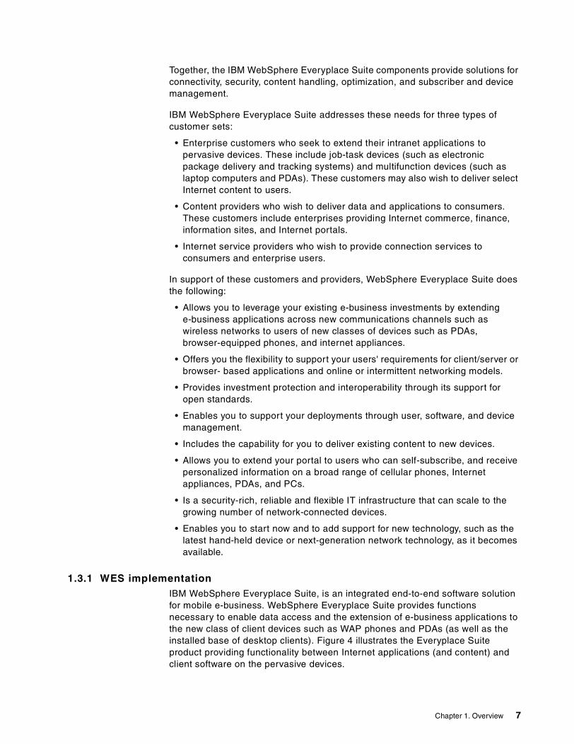
1.3.1 WES implementationIBM WebSphere Everyplace Suite, is an integrated end-to-end software solution for mobile e-business. WebSphere Everyplace Suite provides functions necessary to enable data access and the extension of e-business applications to the new class of client devices such as WAP phones and PDAs (as well as the installed base of desktop clients). Figure 4 illustrates the Everyplace Suite product providing functionality between Internet applications (and content) and client software on the pervasive devices.
Chapter 1. Overview 7

Figure 4. WebSphere Everyplace Suite, end-to-end solution
WebSphere Everyplace Suite can be looked at as an integrated suite that packages many IBM technologies into a comprehensive offering that brings value to the customer through simplified pricing and ordering, easier installation and configuration, and a common security and accounting architecture.
The IBM WebSphere Everyplace Suite provides a solid foundation of products and technologies for extending e-business by providing the following support as illustrated in Figure 4:
• Connectivity
WebSphere Everyplace Suite provides a point of entry into the network for pervasive computing devices. Currently, the IBM WebSphere Everyplace Suite includes the following client connections:
• Internet and third-party infrastructure using the HTTP protocol to connect to the WebSphere Everyplace Suite Authentication Server
• Wireless connectivity (including dial and LAN connections) to the Everyplace Wireless Gateway
• Smart phone connectivity to the WAP Gateway
• MQSeries Everyplace (MQe) client connections via TCP/IP or HTTP
• Synchronization Manager client connections
• Content handling and content transformation
Since pervasive computing devices come in all sizes and have widely varying display capabilities, transmitted content must be customized to fit the capabilities of the requesting device. IBM WebSphere Transcoding Publisher (WTP) technology performs this transformation automatically and on-the-fly. This eliminates the need to store and maintain multiple versions of content.
• Security
The IBM WebSphere Everyplace Suite provides the following security features:
• End-user (client) authentication provided by the Authentication Server and Wireless Gateway
8 Extending e-business to Pervasive Computing Devices Using IBM WebSphere Everyplace Suite V1.1.2

• Secure connections can be established with the Authentication Server via the Secure Sockets Layer (SSL) for server authentication and data encryption
• Secure WAP connections to WAP Gateway via Wireless Transport Layer Security (WTLS)
• Back-end secure connection via SSL between Wireless Gateway and Authentication Serve.
• Directory Server (LDAP) security
• Secure connections for wireless clients connected to radio networks, dial connections (PPP) and LAN connections
• MQSeries Everyplace (MQe) secure connections for online and store-and-forward messaging applications
• Optimization
Scalability is an absolute requirement for handling peak loads and future growth. The following services are provided by WebSphere Everyplace Suite:
• Caching servers provided by the WebSphere Edge Server - Caching Proxy - WebSphere Traffic Express (WTE)
• Load balancing software to distribute traffic among multiple servers provided by the WebSphere Edge Server - Load Balancer.
• Subscriber and device management services
In the world of pervasive computing, a single device may have multiple users, and a single user may access the network using multiple devices. WebSphere Everyplace Suite includes Tivoli technology to manage devices and users separately, easing the burden of administration and system maintenance. In addition, Tivoli Subscription Manager allows you to add value and build loyalty by providing personalized services and personal space for mail, bookmarks, etc. This support is provided by the Tivoli Personalized Services Manager (TPSM).
In addition to this functionality, IBM WebSphere Everyplace Suite Version 1.1.2 also provides for the following support:
• Messaging
A very strong requirement to support online and store-and-forward applications in lightweight devices, such as PDAs and laptop computers.
In addition, the following security issues must be taken into consideration when using WebSphere Everyplace Suite:
• In general, firewalls must be deployed properly in a WebSphere Everyplace Suite (WES) domain. However, firewalls are not included in the WES product.
•In this release, administrators are not authenticated by the WebSphere Everyplace Suite Authentication Server. That is, authentication of administrators is component-dependent (for example, Wireless Gateway Gatekeeper, Transcoding administration console and others).
Note
Chapter 1. Overview 9

Messaging supports mobility and the requirements that arise from the use of potentially fragile communications in pervasive computing networks. WebSphere Everyplace Suite includes MQSeries Everyplace (MQe) to provide the standard MQSeries quality of service (that is, once-only assured delivery). Messages can also be exchanged with other MQSeries family members. Since it is expected to be deployed outside the corporate intranet, it also provides sophisticated security capabilities.
• Data synchronization
Synchronization is a critical capability in the wireless market due to cost, availability of signal, and signal quality. IBM WebSphere Everyplace Suite has the capability to manage the automatic exchange and updating of e-mail, schedules, transactions, and database exchanges between popular hand-held devices (Palm, WorkPad, WinCE and Zaurus) and popular database servers (DB2, Notes, Domino, MQSeries, Oracle, and Exchange). This allows users to perform work offline, and connect to the network whenever it is convenient.
1.4 WES scenario
A common WES scenario is shown in Figure 5. It illustrates how IBM WebSphere Everyplace Suite components fit together. The sample scenario includes users, user enrollment, customer care, ways to connect to the WES domain, end-user authentication provided by the Authentication Server (proxy), the Everyplace Wireless Gateway, WebSphere Transcoding Publisher, and other components.
Figure 5. IBM WebSphere Everyplace Suite - A sample configuration
10 Extending e-business to Pervasive Computing Devices Using IBM WebSphere Everyplace Suite V1.1.2

In this sample scenario, we can see the following:
• WAP devices, wireless clients (radio, dial and LAN) connect to the Everyplace Wireless Gateway (including the WAP Gateway). For more information see 1.6, “Everyplace Wireless Gateway” on page 14.
• Internet clients using the HTTP protocol connect to the Authentication Server. In this scenario, a load balancer is used in front of the Authentication Server. See 1.5, “WES Authentication Server” on page 11.
• If required, a third-party gateway would also connect to the Authentication Server (using the HTTP protocol). For example, a vendor can develop a gateway to support devices not supported by WES.
• For protection, two firewalls are deployed. Firewalls are not provided by WES.
• The Authentication Server (proxy) and the Wireless Gateway implement a handshake process to authenticate end users by using the RADIUS server, and sessions are created in the Active Session Table (AST) database.
• End users enroll by accessing the TPSM enrollment applications. See 1.9, “Subscriber and Device Management Services” on page 21.
• Administrators enroll end users using the TPSM customer-care application.
• For selected applications transcoding canbe enabled using the WebSphere Trancoding Publisher proxy. See also 1.7, “IBM WebSphere Transcoding Publisher” on page 16.
• An LDAP Directory Server is used to store configurations and user, device, and network profiles used for transcoding.
• A caching proxy is used for better performance. Transcoded pages can be cached and the Wireless Gateway can also cache binary WML documents.
• TPSM Device Manager is used to support management of client devices, such as screen-phones, PCs, PDAs, and other portable devices for software distribution, device identification, inventory, and remote configuration. See 1.9, “Subscriber and Device Management Services” on page 21.
• Synchronization Manager clients can access the Synchronization Manager Gateway. See 1.11, “Data Synchronization Manager” on page 25 for details.
• MQe clients can access the MQe Gateway. For more information see 1.10, “MQSeries Everyplace” on page 24.
• The WES administration console is used to launch component specific administration applications. For example, the Wireless Gateway Gatekeeper and the WebSphere Trancoding Publisher administration console.
1.5 WES Authentication Server
The IBM WebSphere Everyplace Suite is designed to achieve single sign-on, namely to authenticate the users only once for their access to the services hosted by the WES domain. This authentication design is achieved by sharing user credentials through a centralized repository. The Authentication Server uses the following components and features:
• It only supports the HTTP protocol, and HTTP basic authentication must be enabled.
Chapter 1. Overview 11

• A RADIUS server provided with WES is actually used for end-user authentication.
• An Active Session Table (AST) is used to store session information.
• The IBM Directory Server (LDAP) is used for configuration and preferences profiles (user, device and network information).
• The Authentication Server provides a handshake scheme based on trusted IP addresses with the Wireless Gateway to authenticate users connected to it (WAP, wireless clients, dial and LAN).
• The Authentication Server supports the Secure Sockets Layer (SSL) for incoming requests. SSL can also be enabled to access back-end resources.
• The Authentication Server in a WES environment can be referred to as the common point of entry, since Everyplace Wireless Gateway (EWG) in turn connects to the Authentication Server. Therefore, it can be used as the starting point for problem determination, given that all traffic must go across it.
Figure 6. End-user authentication and the WES Authentication Server (proxy)
As illustrated in Figure 6, users from the Internet or third-party gateways may connect to the WES Server through the Everyplace Authentication Server. In addition, users may also access the Everyplace Wireless Gateway using three types of links (see also 1.6, “Everyplace Wireless Gateway” on page 14):
• Dial-up connection based on the Point-to-Point Protocol (PPP)
• Wireless client connections over wireless or IP networks
• Wireless connections based on the Wireless Application Protocol (WAP)
12 Extending e-business to Pervasive Computing Devices Using IBM WebSphere Everyplace Suite V1.1.2

The Wireless Gateway communicates with the Authentication Server via HTTP to provide a complete end-user authentication process. The Authentication Server runs in one the two following modes:
• Authentication Proxy (AP)
The Everyplace Authentication Server is the point of entry to the WES domain for devices and users that do not connect through the Everyplace Wireless Gateway. It is the next, non-firewall hop for connections through the Everyplace Wireless Gateway. At least one Authentication Server is required to enable integration of most components.
The Authentication Proxy intercepts all HTTP requests destined for WES services. In AP mode, users can only access services in the WES domain.
• Transparent Proxy (TP)
A Transparent Authentication Proxy also performs user authentication based on HTTP authentication headers. However, the Transparent Authentication Proxy allows other Suite components such as content and application servers to do their own user authentication. A Transparent Authentication Proxy also allows users to access material outside the WES domain (for example, the Internet).
The Authentication Server can also be configured in series to provide a combination of TP and AP scenario. For example, in order for client devices to access both Internet and services hosted by the WebSphere Everyplace Suite, the Authentication Server can be configured in the way illustrated in Figure 7.
In this case, a client can access applications in the WES domain as well as accessing other Internet sites outside the WES domain.
Chapter 1. Overview 13

Figure 7. Authentication Server - AP/TP configuration
In this scenario, the Authentication Server configured in TP mode provides the following function:
• Enables passthrough of Internet-destined traffic.
• Enables secure connections to Internet sites.
1.6 Everyplace Wireless Gateway
IBM WebSphere Everyplace Suite includes the IBM Everyplace Wireless Gateway Version 1.1. The Everyplace Wireless Gateway provides secure wired and wireless connectivity between the IT network and the Communications Network (for example, GSM, CDMA/TDMA, ISDN, GPRS), protocol translation (for example, TCP/IP - WAP), and support for Short Message Service (SMS).
Figure 8 illustrates the Wireless Gateway components that provide support for WAP, wireless, dial and LAN connections. It also includes the Gatekeeper application used for administration of the gateway.
14 Extending e-business to Pervasive Computing Devices Using IBM WebSphere Everyplace Suite V1.1.2

Figure 8. Everyplace Wireless Gateway
The Everyplace Wireless Gateway integrates data access from multiple data packet, radio, cellular and wireline networks to enterprise LAN and WAN networks. In addition to supporting TCP/IP to TCP/IP connections, the Everyplace Wireless Gateway also supports protocol translation between UDP/WSP (WAP) and TCP/IP, thereby enabling the extension of existing LAN/WAN environments to WAP compliant devices.
The Everyplace Wireless Gateway integrates all supported networks within a single gateway host. The gateway can connect radio networks to any wireline network from local area networks (LANs) to wide area networks (WANs). This means that all mobile and stationary units can be linked to the same wireless gateway, regardless of the radio network, and all units can access the same set of applications. Users with different application needs (based on transmission costs, coverage, or devices) can select the best radio network for their situation.
Everyplace Wireless Gateway optimizes communication over the wireless link by implementing a range of optimization techniques that reduce traffic:
• Compression enables the size of each IP packet to be reduced in a way that it can completely be restored at the receiver. This is done without having any knowledge of the content of the IP packet. This increases the effective data rate of the wireless network. It also decreases the amount of data to be transmitted and therefore transmission costs in most cases.
• TCP Header Reduction minimizes redundancy in TCP traffic. TCP normally adds a 40-byte header to each packet it transmits. But for a point-to-point
Chapter 1. Overview 15

connection between the Gateway and client, some of the fields in the TCP header are redundant and can be removed. Everyplace Wireless Gateway removes these redundant header fields.
• Retransmission Optimization reduces the fairly common occurrence of packet retransmissions over TCP. These wasteful retransmissions are caused by insufficient bandwidth availability or high latency over the wireless link. Retransmission optimization in the Gateway and client addresses this problem.
• Short hold mode helps reduce air time on connection-oriented wireless networks and PSTN. In short-hold mode there is no established physical connection over the mobile network, but client and gateway are in a state such that they remain virtually connected. If the client or gateway is requested by the IP stack to transmit an IP packet, this component will re-establish the physical connection and start the transmission immediately. Short-hold mode is entered when there is no traffic on the line for a certain amount of time.
• Supports binary WML caching using the Edge Server Cache Server.
The Wireless Gateway provides the following benefits:
• Companies can support multiple networks, which enables mobile users to use the network that meets their individual needs and cost objectives.
• Everyplace Wireless Gateway supports many worldwide protocols, including DataTac, Mobitex, AMPS, GSM, PSTN, Satellite, and Japanese networks.
• Everyplace Wireless Gateway supports applications using industry-standard sockets programming interface, so users do not need to learn special programming interfaces or proprietary tools and protocols. In effect, TCP/IP applications can run unchanged with wireless networks.
• The comprehensive network access solution features bi-directional user and server authentication and data encryption for security.
• Everyplace Wireless Gateway data compression and header reduction may result in faster response times and lower network fees.
• Everyplace Wireless Gateway automatically disconnects from connection-oriented dial networks during idle periods and reconnects for new data transmissions. This lowers connection fees and preserves a virtual connection when the physical connection is dropped accidentally or intentionally.
• Everyplace Wireless Gateway provides its own Java-based user interface that enables easy setup and configuration across multiple platforms.
1.7 IBM WebSphere Transcoding Publisher
The WebSphere Transcoding Publisher proxy transforms arbitrary content into a form that can be presented on a device that is different from the originally intended target, such as changing HTML content intended for desktop PCs to WML content suitable for the new class of smart phones.
In general, transcoding is the process of transforming content from one format into another, including conversion between alternative screen sizes or window sizes and aspect ratios so that the content can be displayed on a wide and growing variety of devices.
16 Extending e-business to Pervasive Computing Devices Using IBM WebSphere Everyplace Suite V1.1.2

Both enterprise and Web content may be filtered, transformed, converted, or reformatted to enable it to be universally accessed by a variety of devices, to exploit specific application requirements for content customization, and to enable personalization of general content. Moreover, this content may be delivered over a wide range of networks and, as a result, the network bandwidth and latency encountered will vary greatly.
IBM WebSphere Everyplace Suite includes the IBM WebSphere Transcoding Publisher (WTP) Version 1.1.2 product to support content adaptation. The WTP release has been enhanced to support specific integration functions with WES, such as:
• Directory Server (LDAP) support. WTP implementation and support of LDAP enables better information sharing among WES components. The following WTP information is stored by WES Authentication Server in the Directory Server:
Device Profiles Contains characteristics of various device types.
Network Profiles Contains characteristics of various network types.
User Profiles Contains general and connection-specific information about subscribers.
Configuration information Contains configuration for one or more installations of a component or subcomponent
• Active session exploitation as follows:
a. WTP caches aggregated preference information as it is calculated for each new request. The primary benefit is to improve performance by giving transcoders quicker access to relevant preference-based parameters.
b. WTP relies on WES to determine which device and network profiles should be used with each request. It is expected that users profiles will also be used for transcoding personalization in a future release.
• No operation (No-op) transcoding header. This new option in WTP can be used either because all transcoding has already ocurred in the content source (preventing double transcoding), or because the content owner wants to prevent transcoding for copyright reasons. WTP detects the presence of this header and bypasses any WTP plug-ins that could modify the input content.
Chapter 1. Overview 17

Figure 9. WebSphere Transcoding Publisher in WES environment
WebSphere Transcoding Publisher offers the following features:
• A pluggable framework that hosts third-party and IBM-provided transformation plug-ins, or transcoders. New transcoders can be added and can interact with existing transcoders. All plug-ins can leverage a set of core services, such as the ability to acquire preference information in order to respond to different requests for different users or different devices.
• A base set of transcoder plug-ins that transform content. For example, one of the transcoders can select and apply the appropriate eXtensible Stylesheet Language (XSL) style sheet to transcode an eXtensible Markup Language (XML) document for rendering on a particular device.
The framework can also host transcoders for other purposes, such as personalizing Web pages, transcoding printable documents for Web viewing, and converting from legacy formats such as AFP (Advanced Function Presentation) to Internet formats, such as the World Wide Web Consortium’s (W3C) Scalable Vector Graphics (SVG).
Other examples include converting HTML for display on Palm, EPOC or WinCE devices, Image re-sizing, and converting HTML to imode.
• Administrator control over configuration information and preference profiles. Administrators can also view and control message and trace logging.
• The IBM Transcoding Technology toolkit. This is a developer's toolkit which contains a set of samples, instructions, documentation and procedures to enable you to easily build and implement your own custom transcoder plug-ins.
Custom transcoder plug-ins can be used to process additional data formats, to support new pervasive client devices, to extract the most important elements
18 Extending e-business to Pervasive Computing Devices Using IBM WebSphere Everyplace Suite V1.1.2

of a particular full screen application for display on a pervasive client device, or to improve the transcoding associated with specific Web applications
As the use of the Web becomes more commonplace in peoples' work and home lives, there are an increasing number of requirements that WebSphere Transcoding Publisher can easily satisfy:
• Legacy data
WebSphere Transcoding Publisher enables easy mobile access to legacy data. This is crucial to enterprises as their workforces become more mobile and widespread in order to penetrate new e-business markets.
• New standards
Isolating the content presentation from the application enables existing applications to exploit emerging presentation trends, such as Scalable Vector Graphics (SVG), without requiring the application to be rewritten.
• Pervasive devices
In the same way, transcoding allows developers to exploit the capabilities of new client devices as they emerge, without re-writing the application.
• Freedom of choice
Transcoding enables customers to choose from a wider range of client devices.
1.8 WebSphere Edge Server
The WebSphere Edge Server provides highly scalable caching functions on a server to reduce bandwidth costs and improve response times when processing URLs. In addition, WebSphere Edge Server dynamically monitors and load-balances activity across the set of WebSphere Everyplace Suite processors which are deployed in a configuration.
Figure 10 illustrates the caching and load balancer functions provided by the Edge Server.
Although WebSphere Transcoding Publisher (WTP) runs in different models, in the IBM WebSphere Everyplace Suite integration only the proxy model is available (using a caching proxy is optional).
In others words, the servlet (as WebSphere Application Server filters) and JavaBean models are not supported.
Note
Chapter 1. Overview 19

Figure 10. WebSphere Edge Server - caching and load balancing
As illustrated in Figure 10, the following two components are available:
• Edge Server - Caching Proxy (ESCP)
• Edge Server - Load Balancer (ESLB)
1.8.1 Edge Server - Caching ProxyThe Edge Server - Caching Proxy (ESCP) provides highly scalable caching functions associated with receiving requests and serving URLs. With tunable caching capable of supporting high cache hit rates, this component can reduce bandwidth costs and provide more consistently rapid customer-response times.
ESCP provides a valuable and scalable solution to some of the major traffic management problems. These are the main benefits it offers:
• Reduction of costs and constraints on network bandwidth, particularly during periods of peak concurrent activity.
• Scalable infrastructure that provides cost-effective growth paths and essentially unlimited capacity potential with minimum redesign or disruption.
ESCP provides the above benefits irrespective of browser type. For example, WAP phone browsers, PalmOS browsers and EPOC browsers each receive equal benefit from ESCP.
1.8.2 Edge Server - Load BalancerWithin WebSphere Everyplace Suite, ESLB is used to balance the load across servers performing the same kind of function. For example, a WebSphere Everyplace Suite configuration may require multiple processors to execute its TPSM or WebSphere Transcoding Publisher components. In these scenarios,
20 Extending e-business to Pervasive Computing Devices Using IBM WebSphere Everyplace Suite V1.1.2

ESLB will distribute each of the loads (TPSM or WebSphere Transcoding Publisher) across like-function servers so as to provide very high levels of availability.
The Edge Server- Load Balancer provides the following benefits:
• Scalability
As the number of client requests increases, you can add servers dynamically, providing support for tens of millions of requests per day, on tens or even hundreds of servers.
• Efficient use of equipment
Load balancing ensures that each group of servers makes optimum use of its resources by minimizing the hot spots that frequently occur with a standard round-robin method.
• Easy integration
ESLB uses standard TCP/IP protocols. You can add it to your existing network without making any physical changes to the network (provided the servers are all on LANs). It is simple to install and configure.
• Low overhead
ESLB needs only to look at the inbound client-to-server flows. It does not need to see the outbound server-to-client flows. This significantly reduces its impact on the application compared with other approaches, and can result in improved network performance.
• Non-invasive technology
ESLB does not modify any packets, nor does it require any modifications to the operating system on which it runs.
• Content-Based Routing
CBR gives an ESCP administrator the ability to proxy requests to specific servers based on the content requested.
• High availability
The Dispatcher component of ESLB offers built-in high availability, utilizing a standby machine that remains ready at all times to take over load balancing should the primary Dispatcher machine fail.
• Co-location option
The Dispatcher component can be installed on the same machine where one of the application servers reside. This option is particularly useful if you want your Web site to benefit from the high availability and scalability options of the Load Balancing component with a minimal investment. The co-location option is currently available on AIX and Solaris platforms.
1.9 Subscriber and Device Management Services
IBM WebSphere Everyplace Suite includes the Tivoli Personalized Services Manager (TPSM) Version 1.1. TPSM is an integrated solution that enables businesses to manage subscribers and their pervasive devices.
Chapter 1. Overview 21
TPSM provides the following functions:
1. Subscriber Management Services. A comprehensive set of management services including content personalization, enrollment, self-care, customer-care, interfaces to external billing systems, reporting, among others. This function is provided by the TISM component of TPSM.
2. Device Management Services (DMS). It provides for user-initiated software download to client devices. DMS is also a component of TPSM.
3. Tivoli interoperability/integration.
4. Administrator console.
5. Support for integration with third-party subscription management databases
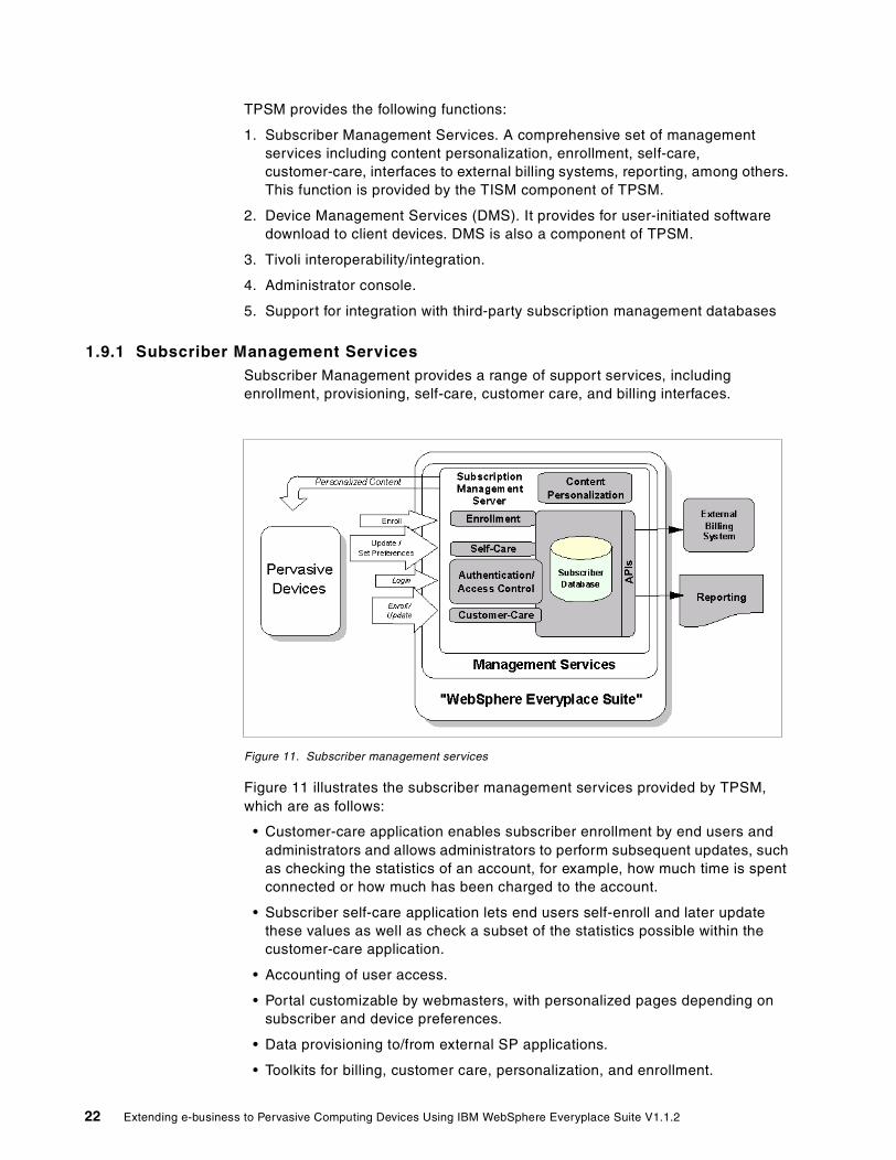
1.9.1 Subscriber Management ServicesSubscriber Management provides a range of support services, including enrollment, provisioning, self-care, customer care, and billing interfaces.
Figure 11. Subscriber management services
Figure 11 illustrates the subscriber management services provided by TPSM, which are as follows:
• Customer-care application enables subscriber enrollment by end users and administrators and allows administrators to perform subsequent updates, such as checking the statistics of an account, for example, how much time is spent connected or how much has been charged to the account.
• Subscriber self-care application lets end users self-enroll and later update these values as well as check a subset of the statistics possible within the customer-care application.
• Accounting of user access.
• Portal customizable by webmasters, with personalized pages depending on subscriber and device preferences.
• Data provisioning to/from external SP applications.
• Toolkits for billing, customer care, personalization, and enrollment.
22 Extending e-business to Pervasive Computing Devices Using IBM WebSphere Everyplace Suite V1.1.2

• Several levels of subscriber grouping are supported and can be configured by the SP (for example, realms, groups, and business accounts).
• Subscriber data can contain both basic preferences (for example, name and address) and ISP specific preferences (for example, hobbies, advertising profile, etc.).
Device Management ServicesDevice Management provides services to support management of client devices such as screen phones, PCs, PDAs, and other portable devices with network access (see Figure 12). Services include software distribution, device identification, inventory, and remote configuration.
Figure 12. Device Management Services (DMS)
Device vendors can extend the framework through a toolkit, enabling the services provided by TPSM to be extended to their specific devices. Features include:
• Device identification services to identify the device when it joins the network.
• Enrollment/initial device setup provides any initial setup required by the device before, during, and after the enrollment process.
• Device configuration provides services for saving and restoring device configuration information for applications such as dialer, web browser, mail and TCP/IP.
• Rest page management is a type of software configuration for device-resident initial start pages. The rest page may contain clickable icons, and advertising remotely changed by the ISP. DMS provides a way to distribute rest pages to devices.
• Software package definition: name, version, hardware and software prerequisites.
Chapter 1. Overview 23

• Software distribution (download) of system and application software.
• Device event management to log, filter, and forward events to the Tivoli server.
• Device Resource API to maintain device information in the TPSM database.
1.10 MQSeries Everyplace
MQSeries Everyplace (MQe) is a toolkit designed with an emphasis on the frugal use of system resources, both in the messaging client and over the associated client network link. It enables pervasive devices to queue messages and transactions, and assure their completion (once and only once), in a secure and efficient manner in both connected (online) and disconnected (offline and store-and-forward) end-user scenarios.
MQe integrates many of the functions that require application programming in other MQSeries family members. Thus encryption and compression are built-in. Similarly, MQe efficiently supports both reliable and unreliable communications (for example, local area networks, PSTN over land lines or mobile links, and communications over selected packet radio networks). This communication support is designed to operate with a minimum of user intervention, with system entities such as channels and transmission queues being effectively hidden from users, programmers, and administrators.
Figure 13 illustrates the MQe client and server configuration in the IBM WebSphere Everyplace Suite environment.
Figure 13. MQe Everyplace in WES environment
MQe supports the EPOC, PalmOS, PocketPC (Windows CE), Windows 95, Windows 98, Windows NT and Windows 2000 device platforms. Java support is offered for EPOC, PalmOS, and Windows CE devices.
MQSeries Everyplace allows mobile workers to access corporate data and applications on many platforms in an MQSeries network with all the trusted benefits of MQSeries such as:
24 Extending e-business to Pervasive Computing Devices Using IBM WebSphere Everyplace Suite V1.1.2

• Industrial strength messaging
• Reliable communications
• Assured, once-only delivery of messages
• Powerful encryption
• Optimized data streams
• Runs on laptops and hand-held devices
• Provides immediate server or mainframe interaction when a link is available, and queues messages when it is not
• Has simple setup options for security, and can easily work through firewalls
• Enables up-to-the-minute information, like stock prices, to be received automatically from servers
1.11 Data Synchronization Manager
Synchronization Manager enables pervasive devices to operate applications “offline”, and synchronize the results of their activities with a server database when connectivity is re-established.
Everyplace Synchronization Manager (ESM) is included in the IBM WebSphere Everyplace Suite bundle. It provides open APIs for application development to allow organizations to transfer information from multiple hand-held devices directly to corporate databases without the need to synchronize via the PC. It enables two-way relational database synchronization with any ODBC database source, two-way file transfer, and the remote installation of applications.
Everyplace Synchronization Manager supports the EPOC, PalmOS, and Windows CE device platforms. Figure 14 illustrates the ESM client and server configuration in the IBM WebSphere Everyplace Suite environment.
Chapter 1. Overview 25

Figure 14. Everyplace Synchronization Manager in WES environment
ESM also supports direct synchronization with Lotus Notes and Microsoft Exchange for server-based synchronization of e-mail, calendars, contacts, and tasks.
Finally, ESM provides the support for synchronizing relational database information between a server relational database and IBM DB2 Everyplace, a compact relational database for PalmOS and Windows CE platforms.
Deploying ESM can increase customer satisfaction by equipping mobile customer-contact personnel with vital information related to their customers. Customers will perceive faster responsiveness, higher credibility, and more value in the relationship.
Specifically, with ESM, users can access and perform updates with applications including:
• Authentication may be done using the existing authentication capabilities of WebSphere Everyplace Suite
• Users can access Notes databases for mail, calendar, address book, to-do lists, memos or corporate application databases
In the IBM WebSphere Everyplace Suite environment, ESM client devices are connected via TCP/IP or as a wireless client (radio network, dial, or LAN connection).
Note
26 Extending e-business to Pervasive Computing Devices Using IBM WebSphere Everyplace Suite V1.1.2

• Users can access Microsoft Exchange for mail, calendar, address book or to-do lists
• Access to corporate relational databases supporting ODBC Version 4
• Binary files can be transferred to hand-held devices
• Server-based e-mail attachments can be sent to Windows CE devices provided a corresponding converter for the type of file exists
• Hand-held program and data files can be backed up and restored to each device
• Each client can establish size limitation parameters for the amount of mail and calendar information they receive
• Each client can connect to the ESM server while cradled to the user’s desktop system, eliminating the need to dial in while at home
• Synchronize relational database information between DB2 Everyplace and a server or mainframe relational database.
1.12 Other software included in WES
Some of the main components in WES require specific software for proper operation. The following software pre-requisites are shipped with WES:
• IBM Directory Server (LDAP) Version 3.2. It is required by the majority of the WES components, including the Wireless Gateway, Transcoding Publisher, Authentication Server, TPSM, and the installation process.
• WebSphere Application Server (WAS) Standard Edition Version 3.5. It is a prerequisite for TPSM.
• IBM HTTP Server Version (IHS) 1.3.12. It is required by TPSM.
• IBM DB2 UDB Version 7.1. It is used by LDAP, Wireless Gateway, and TPSM.
In some specific components, Oracle database can also be used but it is not included in the WES bundle.
• IBM JDK 1.1.8 and JDK 1.2.2 for AIX
Be aware that WAS 3.5, IHS 1.3.12 and DB2 7.1 are licensed for WES usage only.
Note
Chapter 1. Overview 27

28 Extending e-business to Pervasive Computing Devices Using IBM WebSphere Everyplace Suite V1.1.2

Chapter 2. Installation guidelines
IBM WebSphere Everyplace Suite (WES) is the largest integrated suite product offered by IBM to date. The integration of the suite is not only reflected by the functional collaboration among WES components, but also by the centralized installation of the components. This chapter addresses how the WebSphere Everyplace Suite is installed.
2.1 WebSphere Everyplace Suite 1.1.2 functional content
As illustrated in Figure 15, the WebSphere Everyplace Suite connects client devices to Internet and enterprise data.
Figure 15. Suite functional contents
The Everyplace Suite components provide the following services through the corresponding components:
• Connectivity
– Everyplace Wireless Gateway
– Everyplace Authentication Server
– MQSeries Everyplace for Multiplatforms
– Synchronization Manager
• Security
– Everyplace Wireless Gateway
– Everyplace Authentication Server
– Subscriber and Device Management
– Tivoli Personalized Services Manager
• Content Handling
– WebSphere Transcoding Publisher (Proxy model only)
• Optimization
– WebSphere Edge Server - Caching Proxy (Web Traffic Express)
© Copyright IBM Corp. 2001 29

– WebSphere Edge Server - Load Balancer (Network Dispatcher)
• Packaged prerequisites
– SecureWay Directory 3.2
– IBM JDK 1.1.8 and IBM JDK 1.2.2 for AIX
– WebSphere Application Server 3.5 Standard Edition*
– IBM HTTP Server 1.3.12*
– IBM DB2 UDB 7.1*
The previous three packages are licensed for WES purposes only.
• In addition the following components have been added to provide Suite Integration
– Suite Install and Configuration Program
– Suite Administration Console
– Suite Uninstall
2.2 Everyplace component prerequisites
Some of the Everyplace Suite components require other Everyplace Suite components for installation, as well as other prerequisite software. These prerequisite components are listed in Table 1.
Table 1. Suite functional contents
In addition, a Lightweight Directory Access Protocol (LDAP) directory is required for running the Everyplace Suite components. The Everyplace Suite relies on a specific directory schema that is only implemented in SecureWay Directory Version 3.2. Therefore, SecureWay Directory can be seen as a prerequisite for all the Everyplace Suite components. It is strongly recommended that SecureWay Directory be installed within the Everyplace Suite domain.
There are instances when supporting software will automatically be installed, depending on which components and system configuration options you have selected in the installation program. Installation of the following components will automatically result in the installation of the corresponding components:
• SecureWay Directory: When this component is installed, IBM DB2 and the IBM HTTP Server are automatically installed on the server.
Everyplace Suite component Prerequisite components
Everyplace Authentication Server Edge Server - Caching ProxyTivoli Personalized Services Manager (with the domain)
Everyplace Wireless Gateway IBM DB2 Universal Database or Oracle Database (within the domain)
Tivoli Personalized Services Manager WebSphere Application Server Version 3.5IBM DB2 Universal Database or Oracle Database (within the domain)IBM HTTP Server
Edge Server - Load Balancer Edge Server - Caching Proxy
30 Extending e-business to Pervasive Computing Devices Using IBM WebSphere Everyplace Suite V1.1.2

• Tivoli Personalized Services Manager: When this component is installed, WebSphere Application Server and the IBM HTTP Server are automatically installed.
• Everyplace Authentication Server: When this component is installed, the Caching Proxy is automatically installed.
• Edge Server - Caching Proxy: When this component is installed, the Edge Server - Load Balancer administration package and device driver are automatically installed.
2.2.1 WES CD-ROM contentsIBM WebSphere Everyplace Suite Version 1.1.2 is available in a set of 11 CD-ROMs as follows:
1. Everyplace Suite installation program and IBM HTTP Server Version 1.3.12
2. DB2 Version 7.1 EE for AIX
3. DB2 Version 7.1 EE for Solaris
4. LDAP Directory Services Version 3.2 and MQSeries Everyplace Version 1.1
5. IBM WebSphere Application Server Version 3.5 Standard Edition
6. WSCS 1.0 GM part1 (WTE and ND)
7. WSCS 1.0 GM part2 and Everyplace Wireless Gateway Version 1.1
8. IBM WebSphere Transcoding Publisher Version 1.1.2 (includes WES support),Everyplace Suite Console, and Tivoli Personalized Services Manager (TPSM) Version 1.1
9. DB2 Version 7.1 EE DBCS for AIX
10.DB2 Version 7.1 EE DBCS for Solaris
11.Everyplace Synchronization Manager, TPSM Document, and Late Breaking News, 2039.tar
2.3 WES installation overview
IBM WebSphere Everyplace Suite contains many individual components and requires several additional server products. As we can imagine, installing so many components individually is not practical, let alone installing them into a distributed setting. Intuitively, the WES installation is designed to be a centralized installation of all components.
On the other hand, many of the components within WebSphere Everyplace Suite are already mature products with their own unique installation methodology. The centralized WES installation will still utilize the server software installation and upgrade mechanism already in place for the suite components. The suite installation is hence a truly coordinated effort. It determines what common configuration parameters can be “factored out” and supplied only once, but used by multiple components.
In addition, as components are installed and configured on specific systems, the WES installation process captures configuration parameters on writable media, such as diskette, or stores the information into LDAP for subsequent usage later in the installation process. This way, the installation parameters entered by the
Chapter 2. Installation guidelines 31

installer during the component install can be saved for other WES components installation. For the silent installation, script files will be updated based on the saved data. For the attendant installation, the information can be saved on diskette media shared via LDAP by providing URL of the LDAP server.
A case of a coordinated configuration is for example when provided IP address pools defined to be used by the Everyplace Wireless Gateway are also supplied to firewalls in order to protect the WES domain from unauthorized access through third-party gateways and the Internet. In other words, client devices with those IP address can only access the WES domain thru the Everyplace Wireless Gateway.
The architecture for the WES coordinated installation and configuration utility is depicted in Figure 16 on page 32. The installation environment is based on AIX 4.3 or Solaris 7 operating systems. It requires Java Runtime Environment (JRE) Version 1.1.8. The install tool is a Java-based installation and configuration wizard. It permits both silent installation and attentive installation. Both the installation wizard and the configuration process can interact with the LDAP directory to store and retrieve information about component installation and configuration. Finally, the process can generate a status report and log files that you can visually review.
Figure 16. IBM WebSphere Everyplace Suite installation and configuration environment process
To summarize, the WES installation and configuration is designed to achieve the following three principle objectives:
1. Sharing information
A set of wizards are used to collect required parameters for installation and configuration of all WebSphere Everyplace Suite components. This information will be used to run the suite component products’ installation and configuration in a silent mode. The information is also available on a diskette, to be referenced when the suite component products’ installation and configuration is run in an interactive mode. When the installation and configuration is done, this data will be stored in the LDAP directory.
Note: When the previously saved information about the WebSphere Everyplace Suite installation and configuration is found in either removable media or LDAP directories, some of the suite installation and configuration options will not be asked again.
WESInstall/Config
Wizard
Solaris 7AIX 4.3
SilentInstall
StatusReport
JRE 1.1.8
Install Tool for Java
Configuration
LDAP/fsWES
property
AttentiveInstall
32 Extending e-business to Pervasive Computing Devices Using IBM WebSphere Everyplace Suite V1.1.2

2. Silent mode
The WebSphere Everyplace Suite utilizes the native installation commands provided by the operating system. For AIX, this command is installp while for SUN Solaris, this command is pkgadd. The collected installation parameters will be parsed into command line options. This enables the silent mode of the suite installation where no human-machine interaction is required. Once the installation is completed, the suite installation process invokes the component configuration program or shell scripts, with the collected configuration parameters.
3. Interactive mode
The WebSphere Everyplace Suite installation process is designed for interactive installation and configuration as well. The user can provide installation, configuration, and custom information using each component’s installation user interface. The user can also share the information saved by the suite installation program with other installation activities in the same organization. Moreover, selected components may be installed on different file systems. Users can choose a subcomponent selection that satisfies the component interdependencies.
During the interactive installation, the suite installation program will:
• Confirm the selections shown in the summary window
• Prompt the user to insert the proper CD-ROM
• Follow the component’s installation instructions, including configuration in an interactive mode
• Wait until the component installation is complete and seamlessly switch to the next selected component’s installation
In addition, the following WES installation and configuration characteristics might be useful for you during a WES installation:
• WES installation is a media-based (CD ROM) installation. Network installation capability is not available in this release. The content of the media is arranged according to the order by which the components are installed.
• All WES components (except for the Synchronization Manager) are presented to select components and subcomponents you want to install.
• Installing all WES components on a single server is allowed even if it is not a common customer scenario.
• The WES installation pre-checks the required prerequisite products before the dependent components are actually installed.
• If required the WES installation utilizes the operating system install command to invoke the component configuration programs in a silent mode.
WES does not impose specific server requirements at this time. WES permits any combination of products to be installed on any machines. All products can be installed on a single server or installed separately on individual servers in a distributed format. However, scalability and functionality needs will dictate the exact configuration.
It is recommended that the distributed format be used to separate security services, content adaptation, management services, base services, and
Chapter 2. Installation guidelines 33

connection services. On the other hand, centralized environment is achieved by installing all products on a single logical or physical processor, either a larger single processor system, or multiple partitions of the single processor system, or symmetrical multiprocessors known as SMP.
In a distributed environment, most WebSphere Everyplace Suite components can be installed on their own physical machines to provide scalability, higher reliability, and improved performance. Single function machines can be tuned more easily with fewer interruptions due to cross-product problems. However, geographic distribution closer to the devices means smaller network latency and better disaster recovery.
2.4 Supporting WES installation
WebSphere Everyplace Suite integrates its components over a supporting environment. This supporting environment enables information sharing and cross-component communications. The key ingredients for this supporting environment are LDAP directory services, DB2 database, and IBM HTTP Server. This section will explains how these key prerequisites form the supporting environment for the WES domain.
2.4.1 Information sharing and cross component communicationsImportant information is frequently shared by WES components. Enabling such information sharing is part of the effort to achieve suite integration.To achieve this, the WES architecture is based on a common and shared directory structure as well as a dynamically shared database structure. The information about the system, user, device, network, and configurations is stored in the shared directory structure, while more dynamic information (such as session information) is stored in the dynamic database structure. Within WebSphere Everyplace Suite, the directory structure is built on the LDAP server, and the dynamic information sharing is built on DB2 UDB.
Within WES, LDAP acts as a specialized database, providing a central repository describing the infrastructure and component configuration, in addition to its normal operational data. This specialized database is optimized mainly for read access, and information is usually written during the initial install or when new components are added to the WES environment. WebSphere Everyplace Suite implements the IBM SecureWay Directory, which provides Lightweight Directory Access Protocol (LDAP) services. LDAP is an open industry standard that defines a method or communications protocol for accessing and updating information in a directory. For further information on LDAP structure, refer to the redbook LDAP Implementation Cookbook, SG24-5110.
The directory contains the following entries:
• Users • Groups • Profiles • Services
The WES subscriber management service (TPSM) stores user entries in and LDAP directory for people who are enrolled in WES, as described in Chapter 5, “End-user enrollment” on page 89. LDAP user entries are read by other WES
34 Extending e-business to Pervasive Computing Devices Using IBM WebSphere Everyplace Suite V1.1.2

components. However, other WES components will not write or delete user entries. One exception is Everyplace Wireless Gateway. Wireless Gateway may need to modify the user entries in LDAP and it does so by invoking a WebSphere Application Server servlet to call the subscriber management service to connect to the LDAP directory. The servlet is illustrated in Figure 17 on page 36.
Group entries contain a list of users who share common attributes. This is useful for brand management and access control.
The profiles include device and network profiles. Device profiles contain information such as screen size, color depth, and device types. WES components such as the Transcoding Publisher need the device profiles to render the transcoding services. The network profiles contain information such as network name, type, and image processing about the network types.
The service entries contain unique configuration information about each of the WES component.
Directory entries in LDAP are organized hierarchically by their distinguished name (DN). The DN consists of a sequence of parts called relative distinguished names (RDNs), much as a file name consists of a path and directory name in most operating systems. Entries that contain the distinguished name of another entry as a suffix are considered to reside under that entry in the hierarchy structure. The suffix(es) and collection of directory entries forms a hierarchical tree-like structure based on their distinguished names. This tree is called a Directory Information Tree (DIT).
2.4.1.1 SchemasA schema in LDAP is a common information model that defines rules of definitions about objects and their attributes. To organize the information stored in the directory entries, the schema defines object classes. An object class consists of a set of mandatory and optional attributes and each entry in the directory has an object class associated with it.
Schemas define what object classes are allowed where in the directory, what attributes are optional and the syntax of each attribute. For example, a schema could define a person object class, which requires a surname attribute that is a character string.
2.4.1.2 LDAP implementation within WESSubscriber and device enrollment is performed to the WES environment using the Tivoli Personalized Subscription Manager (TPSM) or the Everyplace Wireless Gateway component.
With TPSM, information for each enrolled user is stored by the TPSM in its relational database (RDB) for fast access. This information is also provided by TPSM as a user entry in an LDAP directory.
The common LDAP database should not be confused with other databases in WebSphere Everyplace Suite which are used primarily to store offline information until a user becomes active.
Note
Chapter 2. Installation guidelines 35

Other WES components, such as WebSphere Transcoding Publisher, use LDAP to do the following:
1. Read the user entries
2. Read and write their component specific configuration entries
3. Read and write specific device profile entries
Figure 17 on page 36 illustrates a graphical view of WES integrating the LDAP service and other WES components.
Figure 17. LDAP usage in WES
LDAP Data Interchange Format (LDIF) can be described as a convenient data management mechanism, enabling easy manipulation of data. It is typically used to import and export directory information between LDAP-,based servers, for example when an LDAP server has to be moved to other hardware or to describe a set of changes that are to be applied to the directory.
2.4.1.3 IBM SecureWay DirectoryIBM SecureWay Directory is a central LDAP directory that contains run-time information about active sessions, users, devices, and networks. This database makes it easy for the various components of WebSphere Everyplace Suite (and any server that is added to the configuration) to access the run-time information centrally, without having to replicate the data in other repositories.
The IBM SecureWay Directory is used to access and manage information in a shared directory structure. It allows you to store information in a directory service
TPSM
Schema
LDAP Server
IBM SecureWayDirectory 3.2
UDB
Entries
ACL so only SDP Admincan write entries in SDPsubtree.
Read User EntriesR/W WG User Attributes
R/W Configuration
R/W Configuration
Read User Entries
R/W Configuration
Read Profile Entries
R/W Configuration
Read Profile Entries
Update User Entries
Write User Entries
Write Profile Entries
Update User Entries
UDB
EnrolledUsers
LDIF2DBLDIF
Enroll Users
WESWESInstall/ConfigInstall/Config
WebsphereWebsphereApplicationApplication
ServerServer
WebsphereWebsphereTranscodingTranscoding
PublisherPublisher
WES AuthWES AuthServerServer
SecureWaySecureWayDirectoryDirectory
Servlet
36 Extending e-business to Pervasive Computing Devices Using IBM WebSphere Everyplace Suite V1.1.2

and query it in a database fashion since it has DB2 as its back-end data store. Any LDAP enabled application can store information once, such as user authentication information, and other applications using the LDAP server will recognize it.
SecureWay Directory supports Lightweight Directory Access Protocol (LDAP) Version 3. This is a protocol that provides access to the LDAP directory over a TCP or SSL connection. For SSL secure connections to LDAP, see Chapter 11, “Secure Sockets Layer (SSL)” on page 225.
2.4.1.4 Importing the LDIF file into LDAPIf Everyplace Suite components have been installed prior to the installation of SecureWay Directory, then the LDIF file must be imported into the SecureWay Directory after it is installed and running in the domain. If the SecureWay Directory is installed as part of WebSphere Everyplace Suite, the WebSphere Everyplace Suite schema is installed in the LDAP automatically.
This is done using the ldif2db utility. The following command must be run on the SecureWay Directory server:
ldif2db -i file_name
where ldif2db is the import command and file_name is the name of the LDIF file that was specified during installation.
2.4.1.5 DB2WebSphere Everyplace Suite utilizes the relational database DB2 UDB to store and share dynamic information. In addition, the IBM SecureWay Directory utilizes DB2 database technology as the back-end data store. Utilizing DB2 as the back-end data store provides:
• Industry-leading search performance
• Scale for large directory size
• Reliability, management, and use of database technology
TPSM in the WES domain use DB2 to store user, accounting, and billing information. Everyplace Wireless Gateway uses DB2 for the persistent data storage, while the IBM Everyplace Authentication Server and Everyplace Wireless Gateway use DB2 to store user session information. DB2 is shipped with the IBM WebSphere Everyplace Suite. The IBM Directory has an “optimized” edition of DB2 Version 6.1 bundled in. In addition, WebSphere Everyplace Suite ships DB2 Version 7 with license to be used by TPSM, Everyplace Wireless Gateway, and IBM Everyplace Authentication Server only.
TPSM can only use DB2 UDM Version 7. It is recommended that the LDAP server use its local DB2 Version 6.1 rather than using the remote DB2 UDB Version 7 server.
Note
Chapter 2. Installation guidelines 37

2.5 WES installation process
In this section we explain the installation process step by step. WES provides the installation program tool. A typical WES installation will go through the following steps:
1. Step 1: Starting the WES installation
In this step you start the installation shell script. The tasks performed by the script include checking whether the installation runs with user “root” and with the correct JDK and JRE level.
Note: Be sure to issue these commands from the root directory. Type cd / to get to the root directory. If any command window is in the /cdrom directory, you will not be able to unmount the CD.
For example, use the following command sequence to start the WES installation program:
# mount /cdrom# pwd/# /cdrom/install.sh
This will result in the following output:
CDROM directory = /cdromjava full version "JDK 1.1.8 IBM build a118-20000210 (JIT enabled: jitcV3.1-JDK1.1-20000210)"Now installing Swing 1.1.8.Please enter your JAVA_HOME path:If you press Enter without entering a path, the path will default to/usr/jdk_base
If you install Tivoli Personalized Services Manager, you must also installJava2.Do you want to install Java2 for Tivoli Personalized Services Manager? [y/n]yNow installing Java2 1.2.2 and the PTF.# Java Installer V1.65Copyright (C) IBM 1997-2000
2. Step 2: JDK
The WES installation process installs and configures JDK 1.1.8 and JRE 1.1.8.
3. Step 3: Welcome window
The welcome window is displayed, as shown in Figure 18.
38 Extending e-business to Pervasive Computing Devices Using IBM WebSphere Everyplace Suite V1.1.2

Figure 18. WES installation program welcome window
4. Step 4: Previous install
The WES install process performs a check for any previously installed WES components on the machine.
5. Step 5: Operating system
A check is performed for the right operating system level.
WES requires AIX Version 4.3.3 or higher, or SUN Solaris 7 SPARC with the native threads package. Installation may fail if the right level of OS is not present. The installation program does not support upgrades or operating system fixes.
6. Step 6: License agreement
If required, the license agreement window is displayed.
DB2 UDB Version 7.1 is licensed to be used by WES components only, namely TPSM (see Chapter 5, “End-user enrollment” on page 89), LDAP and Everyplace Wireless Gateway (see Chapter 9, “Wireless Gateway” on page 171).
7. Step 7: View online documentation option
As illustrated in Figure 19 on page 40, an option to view the online IBM WebSphere Everyplace Suite documentation is displayed.
Chapter 2. Installation guidelines 39

Figure 19. View online documentation and Readme file options
8. Step 8: Existing WES installation check
In this step, the WES installation process checks for an existing WES installation. If the same version of WES is found on the machine, the installation process will assume that you want to add new WES components to the server.
On AIX systems, the command lslpp can be used to check for a previous version of WES. On Solaris, the command pkginfo and/or pkgchk can be used.
9. Step 9: Information sharing options
Next, the WES installation process prompts you to enter how you want to share the WES install and configuration information (see Figure 20).
40 Extending e-business to Pervasive Computing Devices Using IBM WebSphere Everyplace Suite V1.1.2

Figure 20. Information sharing options, select an install path
Three options are presented:
– Install SecureWay Directory on this server.
– Retrieve information from LDAP directory.
– Retrieve information from a file system (usually a diskette media).
This is a very critical step during WES installation. The implication of choosing one option is profound and the decision should be made based on the overall deployment architecture.
Table 2 shows an explanation of the actions associated with each of these options.
Table 2. WES install options
Option 1
Setting up SWD, LDAP and Install WES components
Option 2
Retrieving information from LDAP
Option 3
Sharing information via File System
Install SWD Yes No YesSWD is selectable
LDAP Access User ID
Yes Yes and the activeSWD is required
Yes
Import LDIF file Done automatically No need Done automatically
Chapter 2. Installation guidelines 41

10.Step 10: Preparing to share WES install and configuration information
In this step the following options are available:
a. If you select the option to install SecureWay Directory on the server, the SecureWay Directory Configuration window appears asking you to enter data to configure the SecureWay Directory 3.2. The data required includes, for example, the directory suffix, the object type, the directory database name, instance and home directory, as well as the directory server port.
If any version of the SecureWay Directory is found on the server. The installation program allows you to terminate the program, upgrade an older version, refresh a current version, or downgrade from a later version.
b. If you select the option to retrieve information from SecureWay Directory, the SecureWay Directory Server information window appears and asks you for data to access the LDAP server. The request includes the LDAP server name, administrator user ID and password (and password confirm), and the LDAP server port.
The WES installation program can also recover from LDAP connection errors, security errors, or WES Directory Information Tree (DIT) errors. When this happens, the installation program always returns to the LDAP access information input window to allow you to correct the problem. In addition, the WES installation program can also help you to start the LDAP server locally or remotely via the TCP/IP remote execution command.
If an error occurs because the WES DIT was not created, you will have the option to select another LDAP server or create the WES DIT. However, the creation of the WES DIT requires that the LDAP server must have the WES schema already installed.
c. If the user decides to retrieve information from the file system, the Choose File to Retrieve Install/Configuration Information appears and asks the user to locate the file where WebSphere Everyplace Suite installation and configuration information will be saved and retrieved.
The default file name is /tmp/everyplace/everyplace.ldif. You may choose to use a diskette; however, the file size may exceed 1.44 MB. If this is the case, the WES installation program issues a warning message and will ask you for a different file system.
In addition, the everyplace.ldif file can be imported into the SecureWay Directory using either the ldif2db command or the SecureWay client DMT tool provided by LDAP.
For example, for a new LDAP server (see Figure 21) the directory suffix specifies a distinguished name for the directory root. The directory suffix is the highest level entry stored in the directory by a server.
Usage Recommended 1st install in the domain
Recommended subsequent install after the 1st install
Sophisticated user, LDAP install is the last install, when LAN is not available
Option 1
Setting up SWD, LDAP and Install WES components
Option 2
Retrieving information from LDAP
Option 3
Sharing information via File System
42 Extending e-business to Pervasive Computing Devices Using IBM WebSphere Everyplace Suite V1.1.2

Figure 21. New LDAP server sample configuration
The default TCP/IP port numbers are:
– IBM HTTP Server: 80 for server and for administration.
– SecureWay Directory Server: 389
– Tivoli Personalized Services Manager JBDC: 1521 for Oracle, 6789 for DB2
– DB2Instance: 50000/50001
11.Step 11: Retrieving WES installation and configuration data from LDAP
The collected data is stored in local configuration files. The data includes the LDAP server name, access user ID, password, and port number. The password is stored encrypted, using a 40-bit encryption library.
Figure 22 shows the window requesting the administrator’s user ID and password.
Chapter 2. Installation guidelines 43
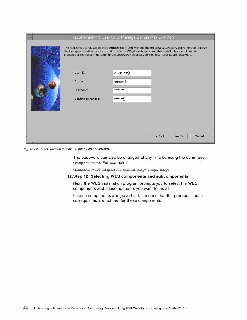
Figure 22. LDAP access administration ID and password
The password can also be changed at any time by using the command ChangePassword. For example:
ChangePassword ldapserver userid curpw newpw newpw
12.Step 12: Selecting WES components and subcomponents
Next, the WES installation program prompts you to select the WES components and subcomponents you want to install.
If some components are grayed out, it means that the prerequisites or co-requisites are not met for these components.
44 Extending e-business to Pervasive Computing Devices Using IBM WebSphere Everyplace Suite V1.1.2

Figure 23. Selecting WES components and subcomponents
As illustrated in Figure 23, you choose the Everyplace Suite components by selecting the check boxes of the WES components you wish to install in a specific machine. All the Everyplace Suite components are displayed in the left-hand pane and you may select any combination of components for installation. The Everyplace Suite components you can select are:
– The Everyplace Authentication Server is the central point of user authentication for the Everyplace Suite. At least one Authentication Server must exist in the Everyplace Suite domain. For details about the Everyplace Authentication Server, see Chapter 6, “User authentication” on page 109.
– The Everyplace Administration Console provides a central location from which to launch the Administration Console of any installed Everyplace Suite component. For details about the Everyplace Administration Console see Chapter 3, “Administration Console” on page 65.
– The Everyplace Wireless Gateway enables Internet Protocol (IP) and Wireless Application Protocol (WAP) applications to run in both wireless and wired environments. It provides wireless access to host and network resources through wireless, dial-up, and wireline networks. For details about the Everyplace Wireless Gateway see Chapter 9, “Wireless Gateway” on page 171.
Chapter 2. Installation guidelines 45

Figure 24. Everyplace Wireless Gateway and subcomponents
Figure 24 illustrates the Everyplace Wireless Gateway and the subcomponents you can install. It includes, for example, the actual Gateway, the administration tool (Gatekeeper), dial support, IP LAN support and others.
– DB2 Universal Database provides reliable data management with complete integrity, high availability, and fast performance.
– Edge Server - Caching Proxy (Web Traffic Express) retrieves, caches and filters Internet data for multiple browser clients.
– Edge Server - Load Balancer (Network Dispatcher) provides dynamic load balancing, scalability, and high availability for servers. It boosts performance by automatically finding the optimal server in a group of servers to handle incoming requests.
46 Extending e-business to Pervasive Computing Devices Using IBM WebSphere Everyplace Suite V1.1.2

Figure 25. Edge Server - Load Balancer (Network Dispatcher) subcomponents
For example, Figure 25 shows the Edge Server - Load Balancer and its subcomponents.
– MQSeries Everyplace extends secure messaging to include dependable communications for mobile workers. It connects laptops, PDAs, phones, and unattended devices, such as servers, enabling users to perform business functions through their mobile devices.
– Tivoli Personalized Services Manager (TPSM) enables service providers to centrally manage subscribers and devices, including subscriber and device enrollment, self-care and customer-care, account maintenance, and billing. See also Chapter 5, “End-user enrollment” on page 89 for information on user enrollment with TPSM.
Figure 26 shows the Tivoli Personalized Services Manager subcomponents.
Chapter 2. Installation guidelines 47

Figure 26. Tivoli Personalized Services Manager (TPSM) and subcomponents
– WebSphere Transcoding Publisher (WTP) adapts Web content based on destination device characteristics and network service level. You can also enhance the WebSphere Transcoding Publisher performance by installing the Edge Server - Caching Proxy (Web Traffic Express). For details about how WebSphere Transcoding Publisher is used in the WES environment see Chapter 7, “Transcoding” on page 129.
13.Step 13: Prerequisites and co-requisites
In this step the WES install process checks for prerequisites and co-requisites. The installation will not continue if the requirements are not met. In some cases, the install program might take some system actions and inform you as shown in Figure 27.
Figure 27. Information message
14.Step 14: Previous install detect
In this step the WES install process checks for the existence of a previous WES installation and takes some action as follows:
48 Extending e-business to Pervasive Computing Devices Using IBM WebSphere Everyplace Suite V1.1.2

– If the installation wizard finds a previous version of the components, you will be prompted to upgrade.
– If it detects a current version of the components, you will be prompted to refresh the installation.
– If it detects a newer version of the components, the user will be prompted to downgrade the installation.
– If the answer is NO, a warning message is displayed indicating that unexpected results may occur.
15.Step 15: Selecting database management system
In this step, you select the database management system you will use in your system. IBM WebSphere Everyplace Suite supports DB2 and Oracle database. Figure 28 shows the window where you select this option.
Figure 28. Selecting database system
For DB2, you also need to specify whether you will use a local or remote DB2 server. For example, when you select Tivoli Personalized Services Manager (TPSM) or Everyplace Wireless Gateway from the component list, then you must also select the option to use either a local DB2 server or a remote DB2 server, as shown in Figure 29.
Chapter 2. Installation guidelines 49

Figure 29. Selecting local or remote DB2 server
When using a remote DB2 database you will need to provide access details. For example, Figure 30 shows the window where you enter the remote DB2 server name, port, instance, and user ID/password to access the database.
Figure 30. Configure remote DB2 server for TPSM
Additional information messages may also be displayed when required. For example, Figure 31 indicates that you need a certain level of the AIX operating
50 Extending e-business to Pervasive Computing Devices Using IBM WebSphere Everyplace Suite V1.1.2
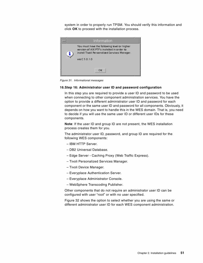
system in order to properly run TPSM. You should verify this information and click OK to proceed with the installation process.
Figure 31. Informational messages
16.Step 16: Administrator user ID and password configuration
In this step you are required to provide a user ID and password to be used when connecting to other component administration services. You have the option to provide a different administrator user ID and password for each component or the same user ID and password for all components. Obviously, it depends on how you want to handle this in the WES domain. That is, you need to decide if you will use the same user ID or different user IDs for these components.
Note: If the user ID and group ID are not present, the WES installation process creates them for you.
The administrator user ID, password, and group ID are required for the following WES components:
– IBM HTTP Server.
– DB2 Universal Database.
– Edge Server - Caching Proxy (Web Traffic Express).
– Tivoli Personalized Services Manager.
– Tivoli Device Manager.
– Everyplace Authentication Server.
– Everyplace Administrator Console.
– WebSphere Transcoding Publisher.
Other components that do not require an administrator user ID can be configured with user “root” or with no user specified.
Figure 32 shows the option to select whether you are using the same or different administrator user ID for each WES component administration.
Chapter 2. Installation guidelines 51

Figure 32. Administrator’s user IDs
Figure 33 shows the panel where you will enter the user ID, group and password when using the same administrator user ID values for all WES components.
52 Extending e-business to Pervasive Computing Devices Using IBM WebSphere Everyplace Suite V1.1.2

Figure 33. Same administrator user ID for all components
Figure 34 shows a sample window (DB2 Universal Database ,in this case) where you will enter the administrator user ID, group, and password for each component. The option to configure a different user ID for each component is selected in the window shown in Figure 32 on page 52.
Chapter 2. Installation guidelines 53

Figure 34. Administrator user ID information by component
17.Step 17: TPSM configuration information
When installing TPSM, you will be prompted for TPSM configuration information as shown in Figure 35.
54 Extending e-business to Pervasive Computing Devices Using IBM WebSphere Everyplace Suite V1.1.2

Figure 35. TPSM configuration
The webmaster user ID must be entered in the TPSM configuration in the following format: webmasterid@domain_name.com.
18.Step 18: Specify Authentication Server configuration information
In this step you will be prompted to enter Authentication Server configuration information, which is common to all Authentication Servers in the WES domain and will be stored in SecureWay Directory (LDAP).
Chapter 2. Installation guidelines 55

Figure 36. Common Authentication Server configuration information (part 1 of 2)
The following Authentication Server values are configured (see Figure 36 and Figure 37):
– Primary Active Session Table (AST) server name: The host name of the primary server that is used to manage the active session table and its entries.
– Maximum RADIUS retries: The maximum number of times that the Authentication Server sends a User Datagram Protocol (UDP) authentication request to a RADIUS server before it gives up.
– RADIUS shared secret: This value is shared (must be exactly the same value) with the RADIUS server to protect (encrypt) the user password.
– Maximum RADIUS retry timeout (milliseconds): The maximum amount of time the Authentication Server waits for a response from a RADIUS server before sending another request for access. The Authentication Server will wait for a response as many times as the specified maximum number of RADIUS retries.
– Maximum session age (minutes): The maximum amount of time the Authentication Server maintains information about a user’s session. After this time has passed, the Authentication Server will clear the information. Server resources, such as disk space, are used while the information is maintained, but once the information is cleared, additional time may be necessary to re-create it.
56 Extending e-business to Pervasive Computing Devices Using IBM WebSphere Everyplace Suite V1.1.2

– Default retry-after delay (seconds): When the Authentication Server is suspended by the administrator, requests to the RADIUS server are rejected. The default retry-after delay value is the default amount of time the device should wait to retry the request.
Figure 37. Common Authentication Server configuration information (part 2 of 2)
– Authentication Server role: The Authentication Server may operate as an Authentication Proxy (AP) that intercepts all requests made to resources within the Everyplace Suite, or as a transparent Authentication Proxy (TP) that allows access to content provided by third-party content servers while using authentication and transcoding.
– Maximum session cache size (Kbytes): The maximum size of the local in-memory cache for this particular proxy.
– AST daemon clean-up interval (seconds): The amount of time in which session information should be cleared from the active session table server.
19.Step 19: Installation summary window
In this step, the WES installation process displays a summary list with all the components to be installed. All the selected components, subcomponents, and configuration information are displayed as illustrated in Figure 38.
Chapter 2. Installation guidelines 57

Figure 38. Installation Summary window
You can click the Back button to go back to the component selection window to add or remove components from the list, or to change other configuration information. When the Install button is clicked, the installation process starts.
20.Step 20: Installation in progress panel
As the installation process commences, a progress indicator is displayed that shows the status of the install. Any errors or problems that occur during the install process are displayed here, they are also logged in the Everyplace Suite log file. Figure 39 shows an example of the installation in progress window.
58 Extending e-business to Pervasive Computing Devices Using IBM WebSphere Everyplace Suite V1.1.2

Figure 39. WES installation in progress window
21.Step 21: Prompt to load next CD
The installation program asks you to unmount, remove, mount and insert the CDs of the components to install. This process is illustrated in Figure 40 and Figure 41 on page 60.
Figure 40. Remove CD
Chapter 2. Installation guidelines 59

Figure 41. Insert new CD-ROM
22.Step 22: Install selected WES components and subcomponents
The following WES components (when selected) are installed and configured in this step:
– BM HTTP Server
– DB2 UDB Version 7.1 Enterprise Edition for SecureWay Directory use only
– IBM SecureWay Directory
– Everyplace Wireless Gateway and Gatekeeper
– WebSphere Application Server
Web server must be stopped before installing WebSphere Application Server (WAS). In some cases, the WES installation program can stop the Web server. In others, the program may tell you to end the install program and shutdown the Web server if it is running. If the installation of the WebSphere Application Server fails, a message is presented and the WES installation program will end.
– IBM Network Dispatcher
If an earlier version of Network Dispatcher has been previously installed, you should uninstall that copy before installing the current version. First, ensure that both the dispatcher executor and the server are stopped. To uninstall use the command installp -u intnd.
– Edge Server - Caching Proxy
– IBM WebSphere Transcoding Publisher
– TPSM (requires DB2 Version 7 or Oracle Version 8.1.5)
– Tivoli DMS
– WES Administration Console
– IBM Everyplace Authentication Server
23.Step 23: Database administrator’s environment
The WES installation process starts the database administrator’s environment configuration.
24.Step 24: Save installation and configuration information
The information is saved and will be used to install other WES components on the same server or install WES components on different servers in the same
60 Extending e-business to Pervasive Computing Devices Using IBM WebSphere Everyplace Suite V1.1.2

network. This information is saved into LDAP or, if the option is selected, a designated file system.
25.Step 25: Readme dialog
The WES installation process displays an option to read the Readme file.
26.Step 26: Installation and configuration failure
If an error occurs, all WES direct configuration and installation will be undone. However, if the WES installation completed successfully, you will need to use the uninstall procedure to undo the installation. See 2.6, “Uninstall” on page 62 for details.
27.Step 27: Product registration
The WES installation process displays the product registration at this time.
28.Step 28: Exit Install
The WES installation process terminates. You will be given the option to start the Administration Console at the end of the Everyplace Suite installation.
2.5.1 Create and Retrieve from LDIF fileIf you selected the option Retrieve existing Everyplace Suite information from a file in the Sharing Options window in Figure 20 on page 41, the installation process will allow you to install without using SecureWay Directory (LDAP).
In this case, you will need to provide the LDIF file where the installation and configuration information will be stored.
The installation information will be retrieved from the file system or diskette at a later time.
In addition, when you select this option, SecureWay Directory (LDAP) will also appear on the component selection panel as a selectable component.
2.5.2 TroubleshootingIf errors occur during installation, you will be notified of the specific problem. Follow the instructions indicated by the error message. Some problems may require termination of the installation wizard. During the installation, all actions and outcomes are logged to an install log file in /tmp/everyplace.log. This file contains a sequence of information that can assist you in identifying and analyzing problems. The /tmp/everyplace_install.trace file contains details about the program execution. These files are in ASCII text format and can be viewed using any text editor.
Other logs to check are:
• /tmp/IBMEPS/Createdb.CREATEDB.log
• /tmp/slapd.errors
These are some tips to avoid problems during the Everyplace Suite installation:
• Install window disappears on Solaris systems
If you click in the background area outside the install window, the install window goes to the background and is not visible. To bring the install window back in view, press the Alt+Tab keys.
Chapter 2. Installation guidelines 61

• Remote X-Windows session install does not work
Installation of Everyplace Suite components must be done on an AIX or Solaris X-Windows workstation. Installation from a remote X-Windows session or emulator is not supported and may cause problems.
2.5.3 Validation procedureThe following procedure can be performed for a quick test of your WES installation:
1. Run the DMT utility to access LDAP.
2. Start the WES Administration Console.
3. Start the Wireless Gateway administration (Gatekeeper).
4. Execute the TPSM validation procedures.
5. Use Authentication Proxy-provided sample configurations (AP and TP modes).
6. Look for any problems in WES install logs.
2.6 Uninstall
Any or all of the Everyplace Suite components can be removed using the Everyplace Suite uninstallation program. The uninstall program allows users to select any combination of Everyplace Suite components and subcomponents to be removed. Only components installed on the local server where the uninstall program is being run can be uninstalled.
WES uninstalls the WES files, folders, and registry entries. Restarting the computer is required after running the WES uninstall, since some server components require rebooting after uninstalling them. Also, WES uninstall will not remove any custom data.
When a WES component is uninstalled, the LDAP entry for this component is also removed from the LDAP directory. Therefore, an active LDAP directory is required to retrieve related information.
Note: The LDAP database will lose integrity if uninstall is done without the proper and active LDAP directory.
2.6.1 Starting the uninstall programTo start the WES uninstall program type in the following commands on the command line:
• On AIX systems: /usr/lpp/IBMEPS.Inst/uninstall.sh
• On Solaris systems: /opt/IBMEPSIn/uninstall.sh
2.6.2 Selecting and uninstalling componentsAfter starting the uninstall program, a list of all currently installed components and their corresponding subcomponents are listed. The subcomponents appear in the right-hand pane and these subcomponents can be individually selected.
62 Extending e-business to Pervasive Computing Devices Using IBM WebSphere Everyplace Suite V1.1.2

Figure 42. Uninstall selection window
There are a number of supporting components (such as the IBM HTTP Server and the WebSphere Application Server) that will automatically be uninstalled when there are no more components installed that need these products as prerequisites.
Note: If any selected components are still required by other components not being uninstalled then you will be notified of this problem before any uninstall takes place.
After all the components have been selected for uninstall, click the Next button. A list of all the components and subcomponents to be uninstalled will be presented. To proceed with the uninstall click the Uninstall button.
A progress window will display the progress of the uninstall and inform you when it is complete. You can view the uninstall log file to verify the results of the uninstallation.
The uninstall program uses the same log as the install does. That is /tmp/everyplace.log and the /tmp/everuplace_install.trace files contain details about the program execution.
Note: The uninstall program will not remove any customer data files. Only files installed during Everyplace Suite component installation will be removed. After uninstalling Everyplace Suite components that use a user ID and a group ID, be sure to delete these IDs from the system to avoid any problems.
2.6.3 DB2 and its database removalUninstallation of IBM DB2 Universal Database will not be allowed until there are no instances of SecureWay Directory (LDAP), Tivoli Personalized Services
Chapter 2. Installation guidelines 63

Manager (TPSM), Everyplace Wireless Gateway (EWG), and Everyplace Synchronization Manager found in the Everyplace Suite domain.
The following resources must be also removed:
• DB2 instances
• DB2 application server
• DB2 user IDs and directories
• Database directory (for example: /db)
2.6.4 Uninstall and SecureWay Directory (LDAP)The uninstall program determines which components are still required by the remaining installed components. This is done by retrieving the Everyplace Suite install and configuration information from the SecureWay Directory (LDAP) server. Therefore, the active LDAP server must be available when the uninstall program is running to ensure the integrity of the Everyplace Suite environment.
Note: As previously mentioned in this chapter, if components are uninstalled without the SecureWay Directory server active, system consistency will be compromised and unexpected results may occur.
64 Extending e-business to Pervasive Computing Devices Using IBM WebSphere Everyplace Suite V1.1.2

Chapter 3. Administration Console
The focal point for administering WebSphere Everyplace Suite is the Administration Console. This chapter briefly describes the console and its associated functions.
3.1 Overview
The IBM WebSphere Everyplace Suite is an integrated suite of products, comprising a number of different components. Although these components are integrated with WebSphere Everyplace Suite, they can be installed independently on a number of different machines, thus having their own unique set of installation and administrative techniques.
Administering each component on a different machine is possible, but performing administration on numerous machines can be a tedious task. In order to eliminate this problem, the WebSphere Everyplace Suite provides a centralized method to launch the administration modules of each component within the WebSphere Everyplace Suite domain. The reason for adopting such an approach is to provide a single interface making navigation and integration between subcomponent administration modules easier and more efficient.
3.1.1 FunctionalityIn this release, the WebSphere Everyplace Suite console administration is simply a Java-based single interface from where administration modules of the WES components can be launched.
It lists all WES components servers that can be launched from configuration information provided by the WES LDAP directory server. However, there is no integration among the suite components’ administration functions.
As a central application, the WebSphere Everyplace Suite Administration Console has to provide some type of validation to ensure that all conditions for use, such as user access rights and prerequisite software, are correct. Figure 43 below provides a graphical illustration of this process.
When the WebSphere Everyplace Suite Administration Console is invoked, the validation is done by accessing the IBM Secureway Directory server (LDAP server), illustrated in Figure 43. The LDAP server provides a central repository that describes the infrastructure and component configuration in a particular WebSphere Everyplace Suite domain over a TCP/IP connection. It obtains the information regarding the installed components and where the servers are installed, and displays that information in a window of the WebSphere Everyplace Suite Administration Console.
The WebSphere Everyplace Suite Administration Console can be installed on AIX and Solaris server workstations only.
Note
© Copyright IBM Corp. 2001 65

Figure 43. Interaction of WebSphere Everyplace Suite Administration Console with components
3.1.2 Starting the Administration ConsoleBeing a Java-based application, the WebSphere Everyplace Suite Administration Console requires a Java Development Kit (JDK) or a Java Runtime Environment (JRE). For the first release of WES, a JDK 1.1.8 is required and it is installed by the WES installation utility
There are three ways to start the Everyplace Administration Console:
1. You will be given the option to start the console at the end of the Everyplace Suite installation process.
2. After installation, you can start the console by clicking the console icon, which was created during the installation process. On AIX, the icon can be found in /home/admin_userID/wesconsole, and on Solaris in /export/home/admin_userID/wesconsole, where admin_userID is the user ID specified in the Everyplace Administration Console installation.
3. After installation, you can also start the console from the command line as follows:
a. Log on with the Administration Console user ID specified during the installation (the Everyplace Administration Console can also be started using the root user ID).
66 Extending e-business to Pervasive Computing Devices Using IBM WebSphere Everyplace Suite V1.1.2

b. Open a terminal window.
c. Execute the following commands:
• In AIX:
cd /usr/lpp/IBMEPS.Admin./wesconsole.sh
• In Solaris:
cd /opt/IBMEPSAd./wesconsole.sh
The Everyplace Administration Console ensures that all of the conditions for use, such as user privileges and prerequisite software, are correct. If the conditions are met, the Everyplace Administration Console displays a list of the installed Everyplace Suite components.
Figure 44. WebSphere Everyplace Suite Administration Console
3.1.2.1 Navigating the WebSphere Everyplace Suite Administration Console
As seen in Figure 44 above, the WebSphere Everyplace Suite Administration Console comprises two main areas, which are the:
• Component List
The Component List, in the left-hand pane, displays a list of all the core components that are installed in the WES domain. As mentioned earlier, this information is retrieved from the LDAP directory, during the launch of WebSphere Everyplace Suite Administration Console.
• Server List
This Server List, in the right-hand pane, displays all the servers that contain an instance of a selected component. The information for this list is also retrieved from the LDAP directory during the launch of WebSphere Everyplace Suite Administration Console.
Chapter 3. Administration Console 67

3.2 Launching a component’s Administration Console
This section provides a brief example of how to launch a particular component’s Administration Console from the WebSphere Everyplace Suite’s Administration Console.
In this example, we launch the WebSphere Application Server Administration Console as follows:
1. To launch the WebSphere Everyplace Suite Administration Console, the user should click the WebSphere Everyplace Suite Administration Console icon on the desktop. The Everyplace Administration Console should be displayed.
2. From the component list in the left-hand pane, select the component you wish to launch. In this case, select the WebSphere Application Server component. See Figure 45.
3. The rest of the component list will be grayed out and the server list will be displayed. From the server list, select the server that contains the instance of the component, as illustrated in Figure 45 on page 68
Figure 45. Selecting the WebSphere Application Server component and corresponding server
4. Once the above steps are complete, the WebSphere Application Server (WAS) Administration Console would be launched, as illustrated in Figure 46.
68 Extending e-business to Pervasive Computing Devices Using IBM WebSphere Everyplace Suite V1.1.2
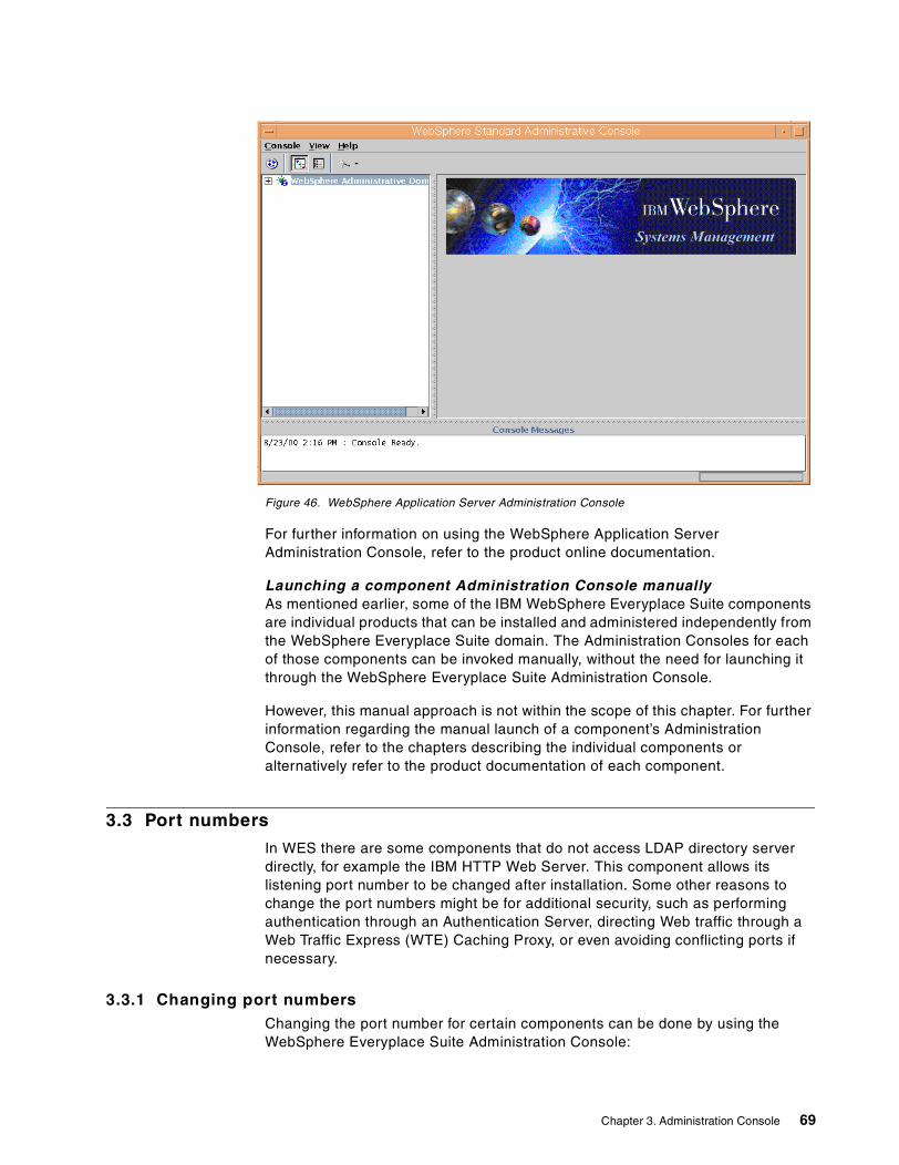
Figure 46. WebSphere Application Server Administration Console
For further information on using the WebSphere Application Server Administration Console, refer to the product online documentation.
Launching a component Administration Console manuallyAs mentioned earlier, some of the IBM WebSphere Everyplace Suite components are individual products that can be installed and administered independently from the WebSphere Everyplace Suite domain. The Administration Consoles for each of those components can be invoked manually, without the need for launching it through the WebSphere Everyplace Suite Administration Console.
However, this manual approach is not within the scope of this chapter. For further information regarding the manual launch of a component’s Administration Console, refer to the chapters describing the individual components or alternatively refer to the product documentation of each component.
3.3 Port numbers
In WES there are some components that do not access LDAP directory server directly, for example the IBM HTTP Web Server. This component allows its listening port number to be changed after installation. Some other reasons to change the port numbers might be for additional security, such as performing authentication through an Authentication Server, directing Web traffic through a Web Traffic Express (WTE) Caching Proxy, or even avoiding conflicting ports if necessary.
3.3.1 Changing port numbersChanging the port number for certain components can be done by using the WebSphere Everyplace Suite Administration Console:
Chapter 3. Administration Console 69

You can change both the IBM HTTP Server and the Caching Proxy’s port numbers after installation, using the WES Administration Console as follows:
1. Select either the IBM HTTP Server or the Caching Proxy from the list of components. A list of all the servers where that component is installed will be displayed in the right-hand pane.
2. Highlight the server you wish to change by clicking that server (do not double-click the name, because that will launch the component’s Administration Console).
3. Right-click the server name (or press Shift+F10). This will display a window with the selected server and port number listed.
4. As shown in Figure 47, enter the new port number in the Port Number field and then click OK.
Note: You cannot edit the Server field.
Figure 47. Changing the port number
5. After clicking OK, the new port number will be displayed in the list of servers in the Everyplace Administration Console.
70 Extending e-business to Pervasive Computing Devices Using IBM WebSphere Everyplace Suite V1.1.2

Chapter 4. WebSphere Everyplace Suite sample scenario
This chapter describes a sample scenario to be implemented as a Web application using several key components provided by the WebSphere Everyplace Suite. We assume that you have a basic understanding of XML, XSL, WML, HTML, Java servlet programming, and the WebSphere Everyplace Suite itself. Refer to An Introduction to IBM WebSphere Everyplace Suite Version 1.1, SG24-5995 for descriptions of associated components and deployment recommendations.
4.1 Overview
The scenario used in this redbook is designed to present the features of the WebSphere Everyplace Suite product in a working example. By implementing a sample application, we should be able to explore issues that otherwise may need extra documentation or consideration.
4.1.1 ScopeWe do not include all WES componentsin this scenario, but only a selection of the key features. Also, keep in mind that this is only a sample application. Concepts concerning features such as security, clustering, scalability and performance are discussed in An Introduction to IBM WebSphere Everyplace Suite Version 1.1, SG24-5995 and will not be implemented in this sample application. We chose to illustrate specific areas of interest that would display the wide range of functionality offered by the WebSphere Everyplace Suite, and provide tips that will aid in implementing your own system.
4.1.2 DescriptionFor this sample application we chose to offer a news service. Users connect to the application using a wireless device and are able to read the news based on subject and headline.
4.1.2.1 Why a news service? Although it is becoming fairly common to receive sports scores and stock updates on your wireless device, we decided to use a news service because it would touch more of the components of the WebSphere Everyplace Suite than, for example, an asynchronous application such as a stock ticker. Such components are the Everyplace Wireless Gateway, the Authentication Server, and the WebSphere Transcoding Publisher, to name a few. Each component and how it will be implemented is described in 4.3, “Topology and component implementation” on page 75.
We could have chosen a complex application such as a traveling employee connecting to his or her intranet checking when a meeting was supposed to start, etc. Such an application would be helpful, but for the sake of simplicity and for a heavier focus on the WebSphere Everyplace Suite components, we chose a small application. Our scenario is more concerned with WebSphere Everyplace Suite features than with Internet application design.
© Copyright IBM Corp. 2001 71

4.1.3 Wireless application designWhen designing a wireless application, there are three initial parameters to determine:
1. Who are our clients?
A client or user agent is the wireless device that will interface with our application. User agents can be anything from WAP-enabled phones to Palm VIIs to a screen phone.
We chose to support a WAP-enabled mobile phone emulator and a PC browser. These user agents have the widest range of physical viewing space and functionality. Mobile phones may have as few as five lines with no color while a laptop could have a full blown Web browser with JavaScript form validation and maybe even a bit of Flash animation.
Our scenario devices will be Netscape 4.7 and the Nokia WAP Toolkit 2.0.
2. What services are we offering?
A service is the functionality that we are offering to our users. Services can range from sending stock updates to your phone to updating your online checking account from your Palm Pilot. Think of it as a way to extend what your device can currently do.
As previously discussed, we chose a news service because it illustrated so many of the WES components.
3. What kind of back end are we integrating with?
In the context of this book, a back end is some kind of information resource that our application will need to connect to. This could be an enterprise database such as DB2, some kind of XML feed, or even a connection to a legacy system using MQSeries.
For our sample scenario we chose to simulate an XML feed to provide IBM news stories. Due to licensing issues, we could not obtain a true XML feed so we chose to fake one by using sample feeds that will reside on the same physical box as our application server. We will need to read in the XML file (our “feed”), apply an XSL style sheet for formatting, then present it to the user in a format they can view using their chosen device.
4.1.3.1 Other considerations: usabilityNow that we’ve figured out what our application is, who will use it, and what resources it will need, we must think about the requirements of a wireless application. The biggest challenge is usability.
On a normal Web browser you can surf to your favorite store’s Web site, browse their inventory, buy a gift for Mother’s Day, look up the latest news on a typhoon out in the Pacific, log in to your company’s intranet to find out when the meeting will be tomorrow morning, and then order a DVD movie to be delivered to your door.
Let’s try that from the beach... on your mobile phone. Browsing the store inventory to pick the perfect gift for mom is kind of clumsy when you have five lines to look at. Trying to find that movie whose title you can’t quite remember isn’t any easier.
72 Extending e-business to Pervasive Computing Devices Using IBM WebSphere Everyplace Suite V1.1.2

The solution in this case is to break down the information, using either categorization or personalization. Categorization is the grouping of related information under a descriptive label: By categorizing the store you’ll follow links (or pages) such as Mother’s Day Gifts->Flowers->Roses->Yellow Roses.
The other solution is personalization. When browsing all the different types of flowers for mom, looking at pictures of the different colored roses is a bit much for your five line phone. It’s a shame you can’t see color on your particular model anyway. The trick here is to let the user personalize what content is sent to the phone. He or she can choose not to see graphics, to look at only horror flicks, and view how well IBM stock is doing.
Let’s go back to our news application. We’d like to view our application on a wide range of user agents - laptop with a wireless modem and a WAP-enabled phone. Creating one application to cover both just isn’t an option: If we make an application for the laptop then the phone will have to keep clicking Continue over and over to see the whole page. If we design the application for the phone, then the laptop will see a page with just five text links.
In order to satisfy both clients, we will need to create two versions of the application - one designed for viewers with a larger screen and another for small screens. Yes, creating two applications is just what your site developer doesn’t want to hear, but if the sources that the application is connecting to are the same, - different navigation is a comparable solution. A suggestion would be to create applications for the large screen, then break down all the information for smaller browsers.
4.2 The solution
In this sample application, we chose to use categorization. In the case of the large screen, users will be given a page listing categories and corresponding headlines. The user then selects a headline to view the full story in the browser. In the case of the small screen version, users will get a menu of subjects. Each subject page will have a list of headlines. When a user chooses a headline, again the full story will be displayed in the browser.
Figure 48 details the different views for a large screen. The user begins at an HTML welcome page and chooses Click here. He is then given a list of categories and corresponding headlines. Choosing a headline, the full story is then displayed for viewing.
Chapter 4. WebSphere Everyplace Suite sample scenario 73

Figure 48. Large-screen version of the sample scenario
Figure 49 illustrates the small-screen version of our scenario. Users begin at a welcome WML page (wes1.wml) that links to the category screen of the application. The user chooses a category, then a headline, and may then finally read the chosen news article.
Figure 49. Small-screen version of the sample scenario
Our application will be driven by the servlet ServeXML_news. This servlet returns an XML file as specified in the URL parameter xml_file. See 4.4.4, “ServeXML_news.java Servlet” on page 84 for instructions on implementing this servlet.
4.2.0.1 Transcoding for HTML and WMLOur application is based on a series of XML files to provide our content. The first welcome page - depending on the client - is in a language native to the client. The default index.htm page that a browser begins on is in HTML. All subsequent
Welcome Pageindex.htm
(original HTML)
Category1Headline1Headline2Headline3
Category 2Headline1Headline2
(transcoded fromXML to WML)
Headlineand News Story...(transcoded from
XML to WML)
Headlineand News Story...(transcoded from
XML to WML)
Headlineand News Story...(transcoded from
XML to WML)
Large-screen version
Welcome WMLPage
wes1.wml(original WML)
Category1Category2Category3
(transcoded fromXML to WML)
Category1Headline1Headline2Headline3
(transcoded fromXML to WML)
Headlineand News Story...(transcoded from
XML to WML)
Headlineand News Story...(transcoded from
XML to WML)
Headlineand News Story...(transcoded from
XML to WML)
Small-screen version
(All one deck in the WAP phone)
Since we are using an emulator to simulate our sample scenario, we chose to write the first WML welcome page (wes1.wml) instead of having the emulator connect directly to our HTML “Welcome” page. The emulator was not designed to allow users to link to outside sites directly from the phone. Such applications were not included with our chosen emulator.
Note
74 Extending e-business to Pervasive Computing Devices Using IBM WebSphere Everyplace Suite V1.1.2

pages are transcoded XML to HTML. For our WAP client, the first page is in WML (wes1.wml) and all other screens are transcoded XMLs.
There are two types of XML files used by our application. The first is the XML containing categories and headlines (MainNewsfeed_new.xml). The second type is the news stories themselves (*_story.xml).
In the HTML version of our application, the user sees one transcoded page of categories and headlines. In the WML version, this file is broken into a deck for easier viewing on a small screen. The first card in the deck displays categories. Each category links to another card that contains headlines. When a user links to a headline, the emulator requests the transcoded news story from the application server.
Both versions of our application are transcoded using two XSL stylesheets. One for HTML and one for WML respectively. Refer to Chapter 7, “Transcoding” on page 129 for details on the WebSphere Transcoding Publisher. Refer to 4.4.2, “Style sheets (XSLs)” on page 78 for sample XSLs.
4.3 Topology and component implementation
We chose to describe the topology of our sample scenario by starting from the user agent and working our way back to the application. Each component will be discussed followed by a walk through of our news application on both clients. Sample code of our servlet, XML files and XSLs are provided 4.4, “Sample Scenario code” on page 77.
Figure 50 depicts our implementation of WES. Considerations such as firewall placement and performance optimization are detailed in An Introduction to IBM WebSphere Everyplace Suite Version 1.1, SG24-5995. We suggest you review this redbook before setting up your WES environment.
The following machines are used in this scenario:
• Everyplace Wireless Gateway
• Authentication Server
• WebSphere Transcoding Publisher
• WebSphere Application Server
• Web Traffic Express (WTE) Caching Proxy
Chapter 4. WebSphere Everyplace Suite sample scenario 75

Figure 50. WES sample scenario
4.3.0.1 Moving through the topologyWe will now describe a request moving through our WES environment. Each component in the scenario shown in Figure 50 and how it is configured will be described in other chapters.
Starting as a request from either the desktop browser (Netscape 4.7 in our case) or our WAP-enabled device (Nokia WAP Toolkit), a request for our news application server enters the Web Traffic Express (WTE) Authentication Server. The HTTP request is on a LAN so that it does not interact with the Wireless Gateway.
Since this is the first request into our WES environment, the Authentication Server returns a prompt to the client asking for a username and password (HTTP basic authentication). The user has already been enrolled in the Tivoli Personalized Services Manager (TPSM) so we enter the appropriate authentication (username including the realm and password).
The user is then validated against the LDAP store of users using the RADIUS server. Among other fields, authentication and user-agent fields are added to the HTTP header of the request. Once the user is authenticated, the request then continues to the WebSphere Transcoding Publisher where the user-agent field in the HTTP header is stored, so that WTP knows how to transcode the reply. In our
76 Extending e-business to Pervasive Computing Devices Using IBM WebSphere Everyplace Suite V1.1.2

case, we need HTML returned to the Web browser and WML to the Nokia emulator.
The request is then compared to the WTE’s cache to see if this request has already been cached. This is a new request, so it is forwarded on to the WebSphere Application Server. The request is processed and the reply is passed back to WTP. WTP transcodes the reply based on the user-agent field and caches the result in WTE before it is forwarded to the Authentication Server. The result is then proxied back to the client.
Alternatively, a WAP request is sent to the Wireless Gateway for authentication. The Wireless Gateway adds proper fields in the HTTP header, including a trusted IP address, and connects to the Authentication Server. Both the Wireless Gateway and the Authentication Server implement a handshake process to authenticate clients. For more information, see Chapter 6, “User authentication” on page 109.
4.4 Sample Scenario code
We have included all sample code and a few examples of our XML files to aid you in your implementation of the WebSphere Everyplace Suite.
4.4.1 Sample XMLs
4.4.1.1 MainNewsfeed_new.xmlThis is the XML that includes both the categories and headlines.
<?xml version='1.0'?><newsfeed>
<news category="Business Partners"><item1>IBM Extends Lead in Emerging $14 Billion Portal Market</item1><item2>IBM Expands Support for Linux</item2><item3>IBM and Vignette Develop Global Strategic E-business
Alliance</item3></news><news category="Research">
<item4>IBM Researchers Create New "Self-assembling" MagneticMaterials</item4>
<item5>IBM Research Breakthrough Doubles Computer Memory Capacity</item5><item6>IBM AS/400e Server Sets Domino Scalability and Performance
Records</item6></news><news category="Redbooks">
<item7>Videos on CD-ROM of IBM ITSO presentations at the 1999 AS400Technical Forum for V4R4</item7>
<item8>AS/400 Internet-Based Education/Presentation Offerings</item8></news>
</newsfeed>
4.4.1.2 Magnetic_story.xmlThis is an example of one of the XML news stories.
<?xml version='1.0'?><newsitem>
<subject>"IBM Researchers Create New "Self-assembling" MagneticMaterials"</subject>
Chapter 4. WebSphere Everyplace Suite sample scenario 77

<story>SAN JOSE, Calif. and YORKTOWN HEIGHTS, N.Y., March 17, 2000 -- IBMresearchers have combined nanotechnology with chemistry to make a radically newclass of magnetic materials that may one day allow computer hard disks andother data-storage systems to store more than 100 times more data than today'sproducts.
</story></newsitem>
4.4.2 Style sheets (XSLs)
4.4.2.1 Style sheet for HTMLBelow is the style sheet used to transcode our XML files to HTML:
<?xml version='1.0'?><!--* Application: IBM WebSphere Everyplace News (IBM WES Redbooks)* File: MainNewsFeed_New.xsl* Version: 0.0* Author: Muhammed Zubayr Omarjee, [email protected]* Created on: 08-09-2000* Description: XSL stylesheet to convert XML to HTML* Modified on: 08-24-2000--><xsl:stylesheet xmlns:xsl='http://www.w3.org/XSL/Transform/1.0'>
<xsl:output method="html"/>
<xsl:template match="newsfeed"><html><head><title>IBM WebSphere Everyplace News - By Subject and Headline</title></head><body bgcolor="#FFFFFF">
<!-- header & logo --><center><table border="0"><tr><td><font face="arial,sans-serif,helvetica" size="3"><b>IBM WebSphere
Everyplace News</b></font></td></tr></table>
<table border="0"><xsl:apply-templates/>
</table>
<!-- footer --><br/><table border="0"><tr align="center"><td><font face="arial,sans-serif,helvetica" size="2"
color="#FF0000"><b>IBM International Technical SupportOrganization</b></font></td></tr>
<tr align="center"><td><font face="arial,sans-serif,helvetica" size="2"><ahref="www.redbooks.ibm.com">http://www.redbooks.ibm.com</a></font></td></tr></table>
</center></body></html>
78 Extending e-business to Pervasive Computing Devices Using IBM WebSphere Everyplace Suite V1.1.2
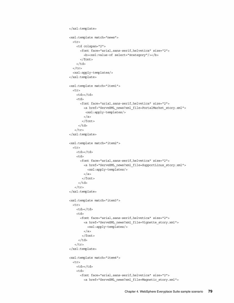
</xsl:template>
<xsl:template match="news"><tr><td colspan="2"><font face="arial,sans-serif,helvetica" size="2"><b><xsl:value-of select="@category"/></b>
</font></td>
</tr><xsl:apply-templates/>
</xsl:template>
<xsl:template match="item1"><tr><td></td><td><font face="arial,sans-serif,helvetica" size="2"><a href="ServeXML_news?xml_file=PortalMarket_story.xml"><xsl:apply-templates/></a></font>
</td></tr>
</xsl:template>
<xsl:template match="item2"><tr><td></td><td><font face="arial,sans-serif,helvetica" size="2"><a href="ServeXML_news?xml_file=SupportLinux_story.xml"><xsl:apply-templates/>
</a></font>
</td></tr>
</xsl:template>
<xsl:template match="item3"><tr><td></td><td><font face="arial,sans-serif,helvetica" size="2"><a href="ServeXML_news?xml_file=Vignette_story.xml"><xsl:apply-templates/>
</a></font>
</td></tr>
</xsl:template>
<xsl:template match="item4"><tr><td></td><td><font face="arial,sans-serif,helvetica" size="2"><a href="ServeXML_news?xml_file=Magnetic_story.xml">
Chapter 4. WebSphere Everyplace Suite sample scenario 79

<xsl:apply-templates/></a></font>
</td></tr>
</xsl:template>
<xsl:template match="item5"><tr><td></td><td><font face="arial,sans-serif,helvetica" size="2"><a href="ServeXML_news?xml_file=Memory_story.xml"><xsl:apply-templates/>
</a></font>
</td></tr>
</xsl:template>
<xsl:template match="item6"><tr><td></td><td><font face="arial,sans-serif,helvetica" size="2"><a href="ServeXML_news?xml_file=Dominorecords_story.xml"><xsl:apply-templates/>
</a></font>
</td></tr>
</xsl:template>
<xsl:template match="item7"><tr><td></td><td><font face="arial,sans-serif,helvetica" size="2"><a href="ServeXML_news?xml_file=ITSOPresentations_story.xml"><xsl:apply-templates/>
</a></font>
</td></tr>
</xsl:template>
<xsl:template match="item8"><tr><td></td><td><font face="arial,sans-serif,helvetica" size="2"><a href="ServeXML_news?xml_file=as400_story.xml"><xsl:apply-templates/>
</a></font>
</td></tr>
</xsl:template>
80 Extending e-business to Pervasive Computing Devices Using IBM WebSphere Everyplace Suite V1.1.2

<!-- news item sheet --><xsl:template match="newsitem"><html><head><title>IBM WebSphere Everyplace News - By Headline - Entertainment</title>
</head><body bgcolor="#FFFFFF">
<!-- header & logo --><center><table border="0"><tr><td><font face="arial,sans-serif,helvetica" size="3"><b>IBM WebSphere
Everyplace News</b></font></td></tr></table>
<!-- headlines will be pulled depending on selected subject --><table border="0"><xsl:apply-templates/></table>
<!-- footer --><br/><table border="0"><tr align="center"><td><font face="arial,sans-serif,helvetica" size="2"
color="#FF0000"><b>IBM International Technical SupportOrganization</b></font></td></tr>
<tr align="center"><td><font face="arial,sans-serif,helvetica" size="2"><ahref="www.redbooks.ibm.com">http://www.redbooks.ibm.com</a></font></td></tr></table>
</center></body></html>
</xsl:template>
<xsl:template match="subject"><tr><td><font size="2" face="arial,sans-serif,helvetica"><b><xsl:apply-templates/></b></font>
</td></tr>
</xsl:template>
<xsl:template match="story"><tr><td><font face="arial,sans-serif,helvetica" size="2"><xsl:apply-templates/>
</font></td>
</tr></xsl:template>
Chapter 4. WebSphere Everyplace Suite sample scenario 81

</xsl:stylesheet>
4.4.2.2 Style sheet for WMLBelow is the style sheet used to transcode our XML files to WML:
<?xml version="1.0"?><!--* Application: IBM WebSphere Everyplace News (IBM WES Redbooks)* File: MainNewsFeedForWAP.xsl* Version: 0.0* Author: Muhammed Zubayr Omarjee, [email protected]* Created on: 08-09-2000* Description: XSL stylesheet to convert XML to WML* Modified on: 08-24-2000-->
<xsl:stylesheet xmlns:xsl='http://www.w3.org/XSL/Transform/1.0'><xsl:template match="newsfeed">
<wml><xsl:text>
</xsl:text><card id="card1">
<p><xsl:apply-templates/>
<do type="prev" label="Back"><prev/></do></p>
</card><xsl:text>
</xsl:text><card id="card2">
<p><a
href="ServeXML_news?xml_file=PortalMarket_story.xml">IBM Extends Lead inEmerging $14 Billion Portal</a><br/>
<ahref="ServeXML_news?xml_file=SupportLinux_story.xml">IBM Expands Support forLinuxIBM Expands Support for Linux</a><br/>
<a href="ServeXML_news?xml_file=Vignette_story.xml">IBMand Vignette Develop Global Strategic E-business Alliance</a>
<do type="prev" label="Back"><prev/></do></p>
</card><xsl:text>
</xsl:text><card id="card3">
<p><a href="ServeXML_news?xml_file=Magnetic_story.xml">IBM
Researchers Create New "Self-assembling" Magnetic Materials</a><br/><a href="ServeXML_news?xml_file=Memory_story.xml">IBM
Research Breakthrough Doubles Computer Memory Capacity</a><br/><a
href="ServeXML_news?xml_file=DominoRecords_story.xml">IBM AS/400e Server SetsDomino Scalability and Performance Records</a>
<do type="prev" label="Back"><prev/></do></p>
</card>
82 Extending e-business to Pervasive Computing Devices Using IBM WebSphere Everyplace Suite V1.1.2

<xsl:text></xsl:text>
<card id="card4"><p><a
href="ServeXML_news?xml_file=ITSOpresentations_story.xml">Videos on CD-ROM ofIBM ITSO presentations at the 1999 AS400 Technical Forum for V4R4</a><br/>
<a href="ServeXML_news?xml_file=AS400_story.xml">AS/400Internet-Based Education/Presentation Offerings</a>-->
<do type="prev" label="Back"><prev/></do></p>
</card></wml>
</xsl:template>
<xsl:template match="news">
<xsl:if test="@category='Business Partners'">
<strong><b><a href="#card2"><xsl:value-ofselect="@category"/></a></b></strong><br/>
</xsl:if>
<xsl:if test="@category='Research'"><strong><b><a href="#card3"><xsl:value-of
select="@category"/></a></b></strong><br/>
</xsl:if>
<xsl:if test="@category='Redbooks'"><strong><b><a href="#card4"><xsl:value-of
select="@category"/></a></b></strong><br/></xsl:if>
</xsl:template>
<xsl:template match="newsitem"><wml>
<xsl:text></xsl:text>
<card><p>
<xsl:apply-templates/><do type="prev" label="Back"><prev/></do>
</p></card>
</wml></xsl:template>
<xsl:template match="subject"><strong><b><xsl:apply-templates/></b></strong><br/>
</xsl:template>
<xsl:template match="story"><xsl:apply-templates/>
</xsl:template>
Chapter 4. WebSphere Everyplace Suite sample scenario 83

</xsl:stylesheet>
4.4.3 WML wes1.wml starting page for the Nokia EmulatorThis is the starting page used by the Nokia Toolkit. By compiling this code, we were able to start with links to our HelloWorldServlet and to our application.
<?xml version="1.0"?><!DOCTYPE wml PUBLIC "-//WAPFORUM//DTD WML 1.1//EN""http://www.wapforum.org/DTD/wml_1.1.xml"><!-- Source Generated by WML Deck Decoder -->
<wml><card>
<p><strong> Select a site below </strong><br/><a
href="http://wesaix04:8001/9.67.130.184/servlet/HelloWorldServlet">HelloWorld</a>
<br/><a
href="http://wesaix04:8001/9.67.130.184/servlet/ServeXML_news?xml_file=MainNewsfeed_new.xml">Everyplace News</a>
<br/></p>
</card></wml>
4.4.4 ServeXML_news.java ServletThe servlet ServeXML_news.java was the driving force behind our application. This servlet reads and sends any XML file that is located in the C:\everyplace_xml_files directory. The file is specified in the URL parameter xml_file. If this parameter is not defined, ServeXML_news will return the HTML file index.htm (which should be located in the same directory as the XML files). If the servlet cannot find the file or there is some problem opening it, the servlet will return an HTML error message.
This servlet can be easily configured for different directory structures by changing the following line to point to your directory. This is especially useful if the servlet is moved to another platform:
File input = new File("C:\\everyplace_xml_files\\" + xml_file);BufferedReader in = new BufferedReader(new InputStreamReader(new
FileInputStream(input)));
This servlet was compiled using both JDK 1.1.8 and 1.2:
/** Application: WebSphere Everyplace News (WES Redbooks)* File: ServeXML_news.java* Version: 0.0* Author: Amy Patton, [email protected]* Created on: 08-09-2000* Parameters: xml_file - file to be displayed to screen, default is index.xml* Description: Servlet to display whatever xml file is given as a parameter* Modified on: 08-15-2000
84 Extending e-business to Pervasive Computing Devices Using IBM WebSphere Everyplace Suite V1.1.2

*/
import java.io.*;import javax.servlet.*;import javax.servlet.http.*;
public class ServeXML_news extends HttpServlet{ public void doGet(HttpServletRequest request, HttpServletResponse response)throws IOException, ServletException
{ String xml_file = request.getParameter("xml_file");
// give default page if no parameterrif (xml_file == null){ response.setContentType("text/html");
xml_file = "index.htm";}else{ // set context to xml
response.setContentType("text/xml");}
// read in the filetry {File input = new File("C:\\everyplace_xml_files\\" + xml_file);BufferedReader in = new BufferedReader(new InputStreamReader(new
FileInputStream(input)));
String line;PrintWriter out = response.getWriter();while((line = in.readLine()) != null)
out.println(line);
in.close();}catch (Exception e) {response.setContentType("text/html");PrintWriter out = response.getWriter();out.println("Problem accessing the file: " + e);
}}
}
4.4.5 HelloWorldServlet.javaThe HelloWorldServelet.java is used in our sample scenario to test the connection to our WebSphere Application Server. This servlet is a sample that is included with the product.
/** @(#)HelloWorldServlet.java1.11 97/10/25** Copyright (c) 1995-1997 Sun Microsystems, Inc. All Rights Reserved.** This software is the confidential and proprietary information of Sun* Microsystems, Inc. ("Confidential Information"). You shall not* disclose such Confidential Information and shall use it only in* accordance with the terms of the license agreement you entered into* with Sun.
Chapter 4. WebSphere Everyplace Suite sample scenario 85

** SUN MAKES NO REPRESENTATIONS OR WARRANTIES ABOUT THE SUITABILITY OF THE* SOFTWARE, EITHER EXPRESS OR IMPLIED, INCLUDING BUT NOT LIMITED TO THE* IMPLIED WARRANTIES OF MERCHANTABILITY, FITNESS FOR A PARTICULAR* PURPOSE, OR NON-INFRINGEMENT. SUN SHALL NOT BE LIABLE FOR ANY DAMAGES* SUFFERED BY LICENSEE AS A RESULT OF USING, MODIFYING OR DISTRIBUTING* THIS SOFTWARE OR ITS DERIVATIVES.** CopyrightVersion 1.0*/
import java.io.*;
import javax.servlet.*;import javax.servlet.http.*;
/*** Hello World. This servlet simply says hi.** <P> This is useful for testing the servlet configuration process,* since this servlet isn't installed.*/publicclass HelloWorldServlet extends HttpServlet {
public void doGet (HttpServletRequest req, HttpServletResponse res)throws ServletException, IOException{PrintWriterout;
res.setContentType("text/html");out = res.getWriter();
out.println("<html>");out.println("<head><title>Hello World</title></head>");out.println("<body>");out.println("<h1>Hello World</h1>");out.println("</body></html>");}
}
4.4.6 Default index.htmThis was the index.htm file that was the starting point for our sample scenario in the Netscape browser. This is also the default page if the servlet ServeXML_news does not have the URL parameter xml_file defined.
<!doctype html public "-//W3C//DTD HTML 4.0 Transitional//EN"><!--
Application: WebSphere Everyplace News (WES Redbooks)File: index.htmVersion: 0.0Author: Amy Patton, [email protected] on: 08-15-2000Parameters: noneDescription: Default page for ServeXML_news.classUsage: The servlet ServeXML_news takes a parameter of
'xml_file=filename.xml' where
86 Extending e-business to Pervasive Computing Devices Using IBM WebSphere Everyplace Suite V1.1.2

'filename.xml is any file in C:/everyplace_xml_files directory. For theservlet to
work correctly the files must be in xml format. When no parameter isprovided, this
page - index.htm (in C:/everyplace_xml_files) is displayed.Modified on: 08-21-2000
-->
<html><head>
<title>IBM WebSphere Everyplace News</title></head><body bgcolor="#FFFFFF">
<!-- header --><center><table border="0"><tr><td><font face="arial,sans-serif,helvetica" size="3"><b>IBM WebSphereEveryplace News</b></font></td></tr></table><br>
<!-- body table here --><table border="0"><tr align="center"><td><font face="arial,sans-serif,helvetica"size="2"><b>Welcome!</b></font></td></tr><tr align="center"><td><font face="arial,sans-serif,helvetica"size="2"><br>Please <ahref="ServeXML_news?xml_file=MainNewsfeed_new.xml">click here</a> to beginviewing your news.</font></td></tr></table>
<br><!-- footer --><table border="0"><tr align="center"><td><font face="arial,sans-serif,helvetica" size="2"color="#FF0000"><b>IBM International Technical SupportOrganization</b></font></td></tr><tr align="center"><td><font face="arial,sans-serif,helvetica" size="2"><ahref="http://www.redbooks.ibm.com">http://www.redbooks.ibm.com</a></font></td></tr></table></center>
</body></html>
Chapter 4. WebSphere Everyplace Suite sample scenario 87

88 Extending e-business to Pervasive Computing Devices Using IBM WebSphere Everyplace Suite V1.1.2

Chapter 5. End-user enrollment
End-user enrollment support is provided by the Tivoli Personalized Service Manager (TPSM) component in WebSphere Everyplace Suite (WES). In this chapter we present an overview and sample scenarios about this service in WES.
5.1 Overview
The Tivoli Personalized Services Manager (TPSM) provides a completely integrated infrastructure of software components for Internet service provisioning. It is an industrial-strength system designed to allow the Internet Service Provider (ISP) to support several separately branded offerings simultaneously, and to provide each brand with a unique marketplace identity, as well as a full range of business offerings.
The Tivoli Personalized Services Manager is designed for continuous operation, flexible enhancement, and high scalability. The system relies on industry-standard hardware and software components with a flexible architecture for integrating additional and varied components. ISPs using the Tivoli Personalized Services Manager can offer their subscribers an unlimited variety of Internet features without having to alter a core base of information management and customer service features in the system’s centralized database. The system's design anticipates growth and allows the Tivoli Personalized Services Manager (TPSM) owner to start with a size that comfortably accommodates the initial anticipated subscriber base while remaining poised to grow exponentially as needed. The TPSM basic configuration is shown in Figure 51.
Figure 51. Tivoli Personalized Services Manager (TPSM) overview
The following TPSM subcomponents are available:
• Database Integration enables the install program or the user to create either a DB2 or Oracle database. If you install Tivoli Personalized Services Manager, you must install this subcomponent.
© Copyright IBM Corp. 2001 89

• Device Manager enables service providers to manage subscribers’ mobile devices, including personal digital assistants, subnotebooks, and screen phones. Device Manager can distribute software to any supported mobile device.
• The Enrollment Server provides a subscriber/device enrollment engine for an Internet Service Provider, including customizable windows and unique banners, messages, billing plans, and payment options.
• Customer Care Support enables representatives to open new or child accounts, deactivate or reactivate accounts, and view and update personal information, service plans, payment methods, and e-mail settings.
• Member Self-Care Support enables subscribers to modify their portals window and some of their profile data, including address and telephone, billing plan, payment method, and registration for premium Tivoli Personalized Services Manager content.
• The Active Session Table (AST) server tracks user and session information.
• RADIUS provides user authentication when the user first signs on. If the user and account are valid, RADIUS allows the session to begin.
• System Management enables services providers to set up a group of users and domains and to create membership plans and deals. It also enables the user to access user profiles.
• The Everyplace Suite Enabler subcomponent allows Tivoli Personalized Services Manager to manage its subscriber database in SecureWay Directory.
• The Portal Toolkit subcomponent enables users to personalize their home pages, including background color, links, etc.
5.2 Enrollment and service provisioning
Every ISP relies on a centrally managed enrollment engine while being allowed total autonomy in presentation and payment plan offers. A standard set of enrollment windows can be customized to deliver uniquely branded messages and graphics as well as ISP-specific billing plans and payment options. Behind the scenes, a consistent array of data elements are captured from each new subscriber, thereby distributing all of Tivoli Personalized Services Manager's additional features to every subscriber, regardless of their ISP.
With individual branding comes unique realm name distinction. Every ISP hosted on Tivoli Personalized Services Manager is granted a realm - which is a partition within the overall database that distinguishes them and their subscribers from all others in the system and the Internet at large. Realms help extend brand name identification.
For example, Realm 1 could be "alpha.com", and Realm 2 could be "beta.com."
Every subscriber to the ISP named "Alpha" would receive a user name and e-mail address that is unique to the realm of "alpha.com" (for example, [email protected], [email protected],,etc.).
Every subscriber enrolled with the ISP named "Beta" would get a user name and e-mail address unique to "beta.com" (for example, [email protected], [email protected], etc.).
90 Extending e-business to Pervasive Computing Devices Using IBM WebSphere Everyplace Suite V1.1.2

Realm distinctions provide benefits to system management. Customer Care Representatives can be granted complete read and write security provisions, but only to specific realms. This keeps the privacy of one realm's data separate and secure from another's.
Figure 52. TPSM enrollment
5.2.1 Subscriber registrationTivoli Personalized Services Manager features a set of enrollment window templates to capture all the information necessary to register a subscriber in the Tivoli Personalized Services Manager system.
The registration windows interface directly with the Tivoli Personalized Services Manager database and capture all registration information. Panels can be added, removed, or rearranged to suit the service provider’s enrollment needs. Graphics and pull-down lists are configurable so that a business can customize the logos that appear in the window and can change some the choices for required entries.
Access codes, which drive the online enrollment process, provide a mechanism for tracking the source of a new subscriber and determine which billing plans and payment options are offered during registration. Automatic credit card checking is available in real time during enrollment to reduce fraud. Flexible filtering of user names ensures the ISP brand of appropriate naming for their subscriber community.
5.2.2 Business account optionsISPs can offer a service to businesses that allows them to create a realm that is synonymous with their company name (for example,"acme.com") and enroll subscribers into that realm. Businesses can own a special business account and only allow approved subscriber candidates to join. Small businesses can take
Chapter 5. End-user enrollment 91

advantage of Tivoli Personalized Services Manager's flexible account hierarchy and open one account and enroll many employees.
5.2.3 Multiple enrollment channelsTivoli Personalized Services Manager offers numerous enrollment channels and flexibility for marketing success. Marketers can solicit new subscribers through Web pages, banner ads, mail-out CDs, the referral service on PC desktops, and even phone calls to customer service/marketing personnel. Enrollment can also be accomplished using a subscriber's hand-held device, taking into account the distinct interface characteristics of the device.
The enrollment windows are easily configured to display whatever logo and enticement text the ISP wants. Deals and payment plans can be flexibly associated with the enrollment channels to allow various payment and pricing options. The enrollment channel is tracked, which allows the ISP to fine-tune its subscriber acquisition channels.
5.2.3.1 Enrollment through a non-PC deviceThe Device Manager feature allows the subscriber to enroll with many different types of small devices such as personal digital assistants (PDAs) and sub-notebooks. These devices do not have a direct way to connect to a service provider's Web site in order to retrieve their initial configuration programs or data. They require a PC and device accessories to do so. Other devices such as screen phones can connect directly however. So when a customer purchases a new device, it may or may not come already preconfigured for a particular service provider. Some service providers have a business relationship with device retailers. A service provider may, therefore, preconfigure the device, in order to offer the consumer Internet access solely by way of a portal that displays the retailer's advertising. If the device does not come preconfigured, configuration may be the first task performed on it after an enrolled subscriber connects for the first time and registers the device with the service provider.
5.2.3.2 Branded CD-ROMsUsing tools provided by leading browser vendors, the Service Provider can create a branded CD, containing a browser, startup files and an installation wizard that shows the subscriber how to temporarily connect to the Internet and begin signing up. The CD package is printed with an access code that the subscriber enters during registration. When sign-up is complete, an Internet sign-up file (INS) is downloaded to the subscriber's PC with dial-in number, DNS address, and account-specific parameters.
5.2.3.3 PC desktop enrollment using the Microsoft Referral ServerFor Windows users who launch the Internet Connection Wizard (ICW) from their PC desktop, the wizard provides a temporary connection to the Internet and the Microsoft Referral Server where the user is presented with a choice of ISPs including the Tivoli Personalized Services Manager's ISP. When a Tivoli Personalized Services Manager ISP is selected, a series of enrollment windows prompt the user for sign-up data. At the end of the sign-up process, an Internet sign-up file is downloaded to the subscriber's PC with dial-in number, DNS address, and account-specific parameters.
92 Extending e-business to Pervasive Computing Devices Using IBM WebSphere Everyplace Suite V1.1.2

5.2.3.4 Web-based enrollmentFor potential subscribers who already have Internet access (through work or school or a friend’s PC) the subscriber goes to a Tivoli Personalized Services Manager Web site and selects a link to the enrollment windows. From there, the person is prompted to enter sign-up data and, when the windows are complete, an Internet sign-up file (INS) is downloaded to the PC. The INS file can be used to customize the current PC or it can be copied to another PC. The INS file configures the browser and dialer with dial-in number, DNS address and account-specific parameters.
5.2.3.5 Banner ad enrollmentPhone enrollment through a Customer Service Representative (CSR) is accomplished by calling a Tivoli Personalized Services Manager Customer Service Representative and talking through the data collection process. The CSR prompts the subscriber for sign-up data and enters it into the online windows of the Tivoli Personalized Services Manager Customer Care application. Subscribers can complete the entire enrollment over the phone or they can simply leave their name and address and get a CD mailed out (and complete the process with a CD-ROM). If the process is completed over the phone, the subscriber is given a login ID and temporary password and talked though the process of configuring their PC with a dial-in number, DNS address and account-specific parameters.
5.2.3.6 Bulk enrollmentFlexible-enrollment APIs allow the ISP to acquire customers through other means and then programmatically enter the subscriber information into Tivoli Personalized Services Manager.
5.3 Customer care services
The customer care component of Tivoli Personalized Services Manager (TPSM) is used by Customer Services Representatives, to provide account management for customers. CSRs use the windows of the customer care component to enroll, query, and modify subscriber accounts. Subscribers contact CSRs by phone and identify themselves with secret personal data (accessible to CSRs on customer care windows). The customer care component provides linkage to custom reports concerning account usage and billing. Customer care windows have free-form text fields for CSRs to post notes and memos. The CSR can display information about the subscriber's personal devices, as illustrated in Figure 53.
Chapter 5. End-user enrollment 93

Figure 53. TPSM customer care services
5.4 Device Manager
The TPSM Device Manager provides a wide range of subscriber device management features, including:
• Enrolling subscribers and their devices • Distributing software to the device • Updating device configuration remotely • Listing the devices owned by a user • Updating rest pages (startup pages) for screen phones
The Device Manager feature provides a flexible framework and a set of services for managing a subscriber's pervasive devices. Device vendors can extend the system's framework and use it to enable their devices to be managed by the Tivoli Personalized Services Manager. Support is provided for several distinct types of devices such as:
• Personal digital assistants (PDAs) • Screen phones • Wireless Access Protocol (WAP) devices
The Device Manager includes device plug-ins, pluggable software that enables administrators to manage the following types of supported physical devices:
• IBM Internet Access Phone Model 500 (for Japan) • Palm Computing PDAs • Compaq Aero 8000 H/PC Pro • PvC client stack
The Device Manager provides and manages connections to:
• e-commerce sites • e-mail • Web sites • Web-based applications
The Device Manager offers easy enrollment and setup:
• Enroll new subscribers and their devices
94 Extending e-business to Pervasive Computing Devices Using IBM WebSphere Everyplace Suite V1.1.2

• Enroll devices for existing subscribers • Perform initial device setup • Change device setups as needed (at any time during enrollment or after)
Figure 54. TPSM Device Manager
The Device Manager offers complete customer service. CSRs have the tools necessary to display subscriber device information. The Device Manager does the following:
• Distributes software to devices.
The service provider can centrally manage software and configure Tivoli Personalized Services Manager to automatically distribute software to subscribers’ personal devices.
• Provides rest page support.
Rest pages are device-resident initial start pages. They may contain clickable icons and advertising that is remotely changed by the service provider. Tivoli Personalized Services Manager Device Manager controls the distribution of rest pages to devices.
• APIs provide flexibility.
The Device Management API allows device and related information to be maintained in the Device Manager database and used by external applications, Device Manager servers, and administrative clients. The Device Management Server API allows for configuration and distribution requests to be queued for distribution to devices. The Device Management Server API allows DMS servlet and device plug-ins to communicate.
5.5 Enrollment: a sample scenario
Before you connect clients to the WebSphere Everyplace Suite domain, users need to be registered. In WES, the Tivoli Personalized Services Manager (TPSM)
Chapter 5. End-user enrollment 95

enrollment function is used to subscribe users. The following section is a walk-through of the Tivoli Subscription Manager.
The registration name and access code are designed for end-user self-enrollment. The registration name is a special user name that is burned onto an enrollment CD or diskette. It is similar to other user names, in that it can be used to log in to the ISP, but it can only access the enrollment domain.
As illustrated in Figure 55, subscriber self-enrollment is provided by Tivoli Internet Services Manager (TISM), a component of TPSM not including the Tivoli Device Manager.
Figure 55. Subscriber self-enrollment
Because it is expensive to burn and distribute custom CDs, a mechanism is needed to allow a wider variety of options at actual enrollment time, which could be several months after a CD was created. Access codes are created for this purpose. They are essentially software-based extensions to the registration name. They are created in the registration database and are not on the enrollment CD. A registration name has one or more access codes. (At a minimum, it has one called “default”.)
A deal describes an enrollment option (such as $19.95 per month for unlimited access). The registration name/access code combination can be associated with one or more deals. The deal also contains a key field that is used to provide linkage to the billing system.
Over-the-phone enrollment doesn’t utilize the registration name as a key element. Subscribers call Customer Service Reps who enter enrollment data into Customer Care component windows. The CSR works with the subscriber to determine what deal they want (and qualify for). The CSR selects the appropriate deal/access code combination based upon their interaction (sometimes the subscriber knows the access code and sometimes they describe a particular deal and the CSR knows which deal/access code combination that is).
As illustrated in Figure 56, over-the-phone customer enrollment is also provided by TISM.
96 Extending e-business to Pervasive Computing Devices Using IBM WebSphere Everyplace Suite V1.1.2
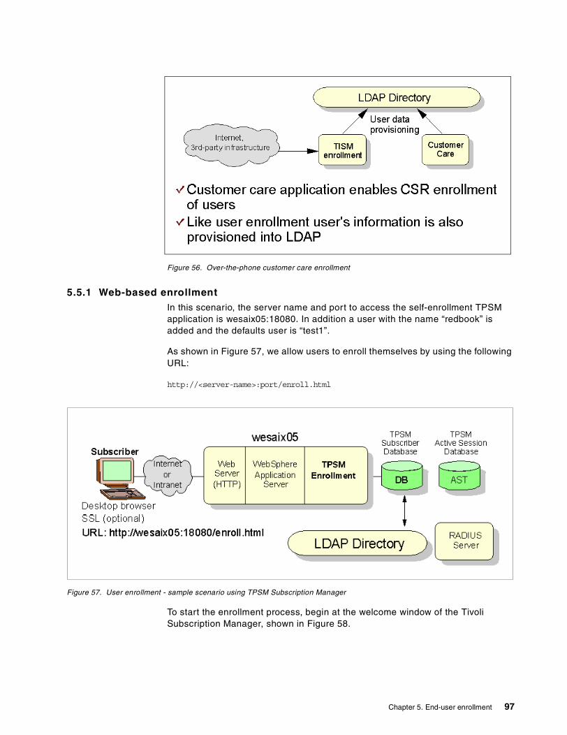
Figure 56. Over-the-phone customer care enrollment
5.5.1 Web-based enrollmentIn this scenario, the server name and port to access the self-enrollment TPSM application is wesaix05:18080. In addition a user with the name “redbook” is added and the defaults user is “test1”.
As shown in Figure 57, we allow users to enroll themselves by using the following URL:
http://<server-name>:port/enroll.html
Figure 57. User enrollment - sample scenario using TPSM Subscription Manager
To start the enrollment process, begin at the welcome window of the Tivoli Subscription Manager, shown in Figure 58.
Chapter 5. End-user enrollment 97

Figure 58. Tivoli enrollment welcome window
Clicking the ENROLL NOW button brings the user to Figure 59. Type Default as the access code.
Figure 59. Default access code for the Tivoli Subscription Manager
98 Extending e-business to Pervasive Computing Devices Using IBM WebSphere Everyplace Suite V1.1.2

The user begins by thoroughly reading the enrollment agreement, shown in Figure 60, and choosing to accept the terms.
Figure 60. IBM Realm Account registration section 1
Figure 61 is the second half of the terms and conditions window.
Figure 61. IBM Realm Account registration section 2
Chapter 5. End-user enrollment 99

After selecting to accept the terms, the user is given a form to enter personal information. See Figure 62.
Figure 62. Personal information
In section 2 of this form, shown in Figure 63, the user may choose between different billing plans. For this example, we select the $19.95 plan.
Figure 63. Choosing a membership plan
100 Extending e-business to Pervasive Computing Devices Using IBM WebSphere Everyplace Suite V1.1.2

In Figure 64, we choose a user name by following the instructions in the form. Our user name will be redbook@ibm, where ibm is the realm. We then continue to the next form. We also provide the password (“redbook” in this case).
Figure 64. Creating a user name and entering a password
In Figure 65, the user chooses an appropriate dial-in number. There are no phone numbers yet and since we are using a LAN connection to the Authentication Server, a number is unnecessary.
Chapter 5. End-user enrollment 101
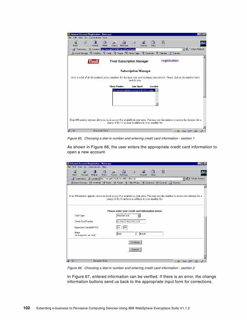
Figure 65. Choosing a dial-in number and entering credit card information - section 1
As shown in Figure 66, the user enters the appropriate credit card information to open a new account.
Figure 66. Choosing a dial-in number and entering credit card information - section 2
In Figure 67, entered information can be verified. If there is an error, the change information buttons send us back to the appropriate input form for corrections.
102 Extending e-business to Pervasive Computing Devices Using IBM WebSphere Everyplace Suite V1.1.2

Figure 67. Verifying personal and credit card information
Once you have verified the information and clicked Continue, a Congratulations window is obtained. Continuing from this form will give you instructions on reconnecting to the WES domain using a dial-in number. This is similar to signing up for an ISP using an 800 number and then reconnecting to a local number. Since we are using a LAN, this does not apply to us.
Figure 68. Final Congratulations window of enrollment
Chapter 5. End-user enrollment 103

5.5.2 LDAPBesides entering users in the enrollment database, new users are also added to the LDAP directory server, as illustrated in Figure 69.
Figure 69. User accounts in LDAP
Tivoli Subscription Manager has a daemon that then enters the user information into the central LDAP database. Refer to An Introduction to IBM WebSphere Everyplace Suite Version 1.1, SG24-5995 for a description of the Subscription Manager.
5.5.3 Banner ad enrollmentThe Customer Care component of Tivoli Personalized Services Manager is used by Customer Services Representatives to provide account management for customers. CSRs use the windows of the Customer Care component to enroll, query, and modify subscriber accounts. Subscribers contact CSRs by phone and identify themselves with secret personal data (accessible to CSRs on Customer Care windows). The Customer Care component provides linkage to custom reports concerning account usage and billing. Customer Care windows have
104 Extending e-business to Pervasive Computing Devices Using IBM WebSphere Everyplace Suite V1.1.2

free-form text fields for CSRs to post notes and memos. The CSR can display information about the subscribers’ personal devices.
Every CSR needs a login ID and access control profile. CSRs must be enrolled in the Customer Care system by an authorized administrator and assigned a login name and password. The access control profile controls the realms and the types of accounts that the CSR can access.
To log in, the CSR launches the Customer Care component, enters his/her login name and password on the login window (shown in Figure 70), and clicks OK.
Figure 70. Logging on to TPSM Customer Care
To update/view an existing subscriber, the CSR clicks Search on the menu bar to get to the search window. Then he/she enters the search criteria and clicks the Search button.
Chapter 5. End-user enrollment 105

Figure 71. Searching subscribers
The subscribers that satisfy the matching criteria are displayed in the list box at the bottom of the window (see arrow in Figure 72). A subscriber can be selected by double-clicking the subscriber’s name, and then the system will launch the maintenance window populating the subscriber information. The CSR can then make changes to the information, if required.
106 Extending e-business to Pervasive Computing Devices Using IBM WebSphere Everyplace Suite V1.1.2

Figure 72. Search results
To enroll a new subscriber, the CSR clicks the New Person button on the menu bar at the top of the pane. This will bring a new, blank enrollment window. The CSR fills in the data provided by the subscriber and clicks Enroll.
Figure 73. Enrolling a new subscriber
Chapter 5. End-user enrollment 107

To create a business account for a business organization, the CSR selects New Business from the menu bar at the top of any Customer Care window. This brings up the window shown in Figure 74.
Figure 74. Creating a business account
After all the required fields are completed and the meaningful optional fields are entered, the CSR clicks the Enroll button.
108 Extending e-business to Pervasive Computing Devices Using IBM WebSphere Everyplace Suite V1.1.2

Chapter 6. User authentication
In WebSphere Everyplace Suite (WES), end-user authentication for HTTP-connected client devices is provided by the Everyplace Authentication Server. Moreover, the Everyplace Wireless Gateway implements a handshake scheme with the Authentication Server in order to authenticate wireless, WAP, dial-in and LAN-connected clients. In this chapter, we present an overview and sample scenarios for the most common configurations of the WES Authentication Server.
6.1 Overview
As illustrated in Figure 75, WebSphere Everyplace Suite allows users to connect to the Suite through the Everyplace Wireless Gateway and the Everyplace Authentication Server.
Figure 75. Points of entry to the IBM WebSphere Everyplace Suite
Users from the Internet or third-party gateways connect directly to the Everyplace Authentication Server using the HTTP protocol. Other users may also access the Everyplace Wireless Gateway using the following supported links:
• Dial-up connections based on the Point-to-Point Protocol (PPP) • Wireless client connections over wireless or IP networks • Wireless connections based on the Wireless Application Protocol (WAP)
In either case, user connections must be authenticated before users can access the application servers in the WES domain. For a more detailed overview about how end-user authentication is accomplished in the WES environment, see An Introduction to WebSphere Everyplace Suite Version 1.1, SG24-5995. In this chapter, we focus our scenarios on the authentication done by the Everyplace Authentication Server for users from the Internet or third-party gateways.
The Everyplace Authentication Server is the point of entry to the WES domain for devices/users that do not connect through the Everyplace Wireless Gateway. It is also the next, non-firewall hop for connections through the Everyplace Wireless
WebSphereEveryplace Suite
ApplicationServers
ExternalNetworks
HTTP/IPtraffic
Dial-in
WAP / Wireless
EveryplaceWirelessGateway
EveryplaceAuthentication
Server
WirelessGatewayClients
© Copyright IBM Corp. 2001 109

Gateway. At least one Authentication Server is required to enable integration of most WES components.
Since no data-link-level authentication can be performed by the WebSphere Everyplace Suite for the connections from the Internet and third-party gateways, all authentication for these connections must take place at the HTTP level by the Everyplace Authentication Server. The client or the third-party gateway acting as the proxy for the client must support HTTP basic authentication, allowing the Everyplace Authentication Server to challenge the client for a user name and password for a particular domain.
The Everyplace Authentication Server runs on the Edge Server - Caching Proxy and is invoked as a Caching Proxy plug-in. Web Traffic Express is a prerequisite for the Everyplace Authentication Server on any machine where it is to be installed.
6.1.1 Everyplace Authentication Server modesThe Everyplace Authentication Server is a component of the Everyplace Suite that performs connectivity functions acting as a point of entry to the Everyplace Suite domain for devices/users that do not connect through the Everyplace Wireless Gateway, and security functions authenticating users defined to the Everyplace Suite when they attempt to access Everyplace Suite services.
The Authentication Server allows for single-user sign-on for all services within the Everyplace Suite domain. User authentication will need to be done once to access services requiring a user ID and password. The Authentication Server can be configured in one of two modes:
• Authentication Proxy (AP): Performs user authentication based on HTTP authentication headers. No other content server in the Everyplace domain may do its own user authentication. Users authenticated through the Authentication Proxy may not access content outside the Everyplace Suite domain. In this mode, the Web Traffic Express must be configured as a reverse proxy.
• Transparent Authentication Proxy (TP): Performs user authentication based on HTTP proxy authentication headers. Content servers in the Everyplace Suite domain may do their own user authentication. The Transparent Authentication Proxy allows users to access material outside the Everyplace Suite domain (for example, the Internet).
6.1.2 HTTP access authentication frameworkThe HTTP protocol (RFC 2616) defines a simple framework for access authentication schemes. The assumption is that a certain group of pages, usually referred to as a protected realm or just a realm, should only be accessible to certain people who are able to provide credentials if challenged by the server.
If an HTTP client, such as a Web browser, requests a page that is part of a protected realm, the server responds with a 401 Unauthorized status code and
The Authentication Server runs on a server hosted by Edge Server - Caching Proxy (Web Traffic Express or WTE) and is invoked as a Caching Proxy plug-in.
Note
110 Extending e-business to Pervasive Computing Devices Using IBM WebSphere Everyplace Suite V1.1.2

includes a WWW-Authenticate header field in his response. This header field must contain at least one authentication challenge applicable to the requested page.
Next, the client makes another request, this time including an authentication header field that contains the client's credentials applicable to the server's authentication challenge.
If the server accepts the credentials, it returns the requested page. Otherwise, it returns another 401 Unauthorized response to inform the client the authentication has failed.
The exact contents of the WWW-Authenticate and authentication header fields depend on the authentication scheme being used. As of this writing, two authentication schemes are in wide use.
6.1.3 Basic access authenticationThe basic authentication scheme assumes that the client's credentials consist of a user name and a password, where the latter is a secret known only to the user and the server.
The server's 401 response contains an authentication challenge consisting of the token "Basic" and a name-value pair specifying the name of the protected realm. For example:
WWW-Authenticate: Basic realm="Control Panel"
Upon receipt of the server's 401 response, your Web browser prompts you for the user name and password associated with that realm. The authentication header of your browser's follow-up request again contains the token "Basic" and the base64-encoded concatenation of the user name, a colon, and the password.
Authentication: Basic QWRtaW46Zm9vYmFy
The server base64 decodes the credentials and compares them against the user name-password database. If it finds a match, the user is in.
The major drawback of the basic authentication scheme is that it is relatively simple for eavesdroppers to steal a password, since it is transmitted in plain sight.
Note: HTTP basic authentication architecture also allows for the use of a message digest instead of a base64 encoding procedure. However, the WES Authentication Server does not support it in this release.
6.1.4 Security considerationsThe following security points must be considered when enabling HTTP basic authentication (required by the WES Authentication Server) for clients connected directly to the Authentication Server:
• You should keep in mind that all data (except for your password) is transmitted in plain view, fully accessible to potential eavesdroppers.
• The password is base64 encoded and relatively easy to decode.
• There is no way for the client to establish that it is actually connected to the server it intends to communicate with. Basic authentication does not provide a mechanism that allows the server to authenticate itself to the client.
Chapter 6. User authentication 111

6.1.5 How reverse proxy worksThe Authentication Server may serve as one of two proxy types or roles: as an Authentication Proxy that intercepts all requests made to resources within the Everyplace Suite, or as a Transparent Authentication Proxy that allows access to content provided by third-party content servers while taking advantage of Everyplace Suite authentication and transcoding.
Note: If you are using the Authentication Server in Authentication Proxy mode (AP), then you have to configure the Authentication Proxy as a reverse proxy.
In a reverse proxy scenario, a client machine does not need to be aware that a reverse proxy exists. The user on the client machine goes to the WTE reverse proxy server’s URL, and the WTE reverse proxy server actually goes through its designated SOCKS server to get the page from the specified Web server behind the firewall as defined in its proxy configuration file. This is transparent to the end user, who only has to invoke a Web page from a publicized URL. It is WTE that returns the requested pages to the client. Therefore, from the client’s perspective, the WTE reverse proxy server represents the Web server.
6.1.6 ConfigurationThe following main configuration files are used by the Authentication Server:
1. WTE configuration. Since the Authentication Server runs as a plug-in of the WebSphere Traffic Express (WTE), it must be properly configured. The WTE proxy functionality is regulated according to the directives contained in its configuration file. This file is ibmproxy.conf and its path for the supported platforms (AIX and Solaris) is by default /etc/ibmproxy.conf.
2. Authentication Server configuration options and values are stored in the ibmwesas.conf file. For example, the following values are configured:
• RADIUS access parameters (names, retries, retry time-out)
• AST access parameters (name)
• Services file contains port numbers
• Primary and secondary servers specified
• Session age maximum, cleanup interval
• Cache size
• Role (Authentication Proxy or Transparent Authentication Proxy)
3. Global configuration information is stored in the /etc/services file, for example, the ports used by the AST and RADIUS servers.
For more specific information see 6.2, “Sample scenario: Authentication Proxy (AP)” on page 113 and 6.3, “Sample scenario: Transparent Authentication Proxy (TP)” on page 121.
For protection of passwords and server authentication, we recommend implementing Secure Sockets Layer (SSL) between clients and the WebSphere Traffic Express (with Authentication Server plug-in) machine.
Recommendation
112 Extending e-business to Pervasive Computing Devices Using IBM WebSphere Everyplace Suite V1.1.2
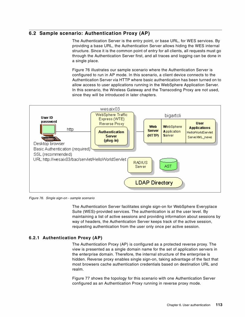
6.2 Sample scenario: Authentication Proxy (AP)
The Authentication Server is the entry point, or base URL, for WES services. By providing a base URL, the Authentication Server allows hiding the WES internal structure. Since it is the common point of entry for all clients, all requests must go through the Authentication Server first, and all traces and logging can be done in a single place.
Figure 76 illustrates our sample scenario where the Authentication Server is configured to run in AP mode. In this scenario, a client device connects to the Authentication Server via HTTP where basic authentication has been turned on to allow access to user applications running in the WebSphere Application Server. In this scenario, the Wireless Gateway and the Transcoding Proxy are not used, since they will be introduced in later chapters.
Figure 76. Single sign-on - sample scenario
The Authentication Server facilitates single sign-on for WebSphere Everyplace Suite (WES)-provided services. The authentication is at the user level. By maintaining a list of active sessions and providing information about sessions by way of headers, the Authentication Server keeps track of the active session, requesting authentication from the user only once per active session.
6.2.1 Authentication Proxy (AP)The Authentication Proxy (AP) is configured as a protected reverse proxy. The view is presented as a single domain name for the set of application servers in the enterprise domain. Therefore, the internal structure of the enterprise is hidden. Reverse proxy enables single sign-on, taking advantage of the fact that most browsers cache authentication credentials based on destination URL and realm.
Figure 77 shows the topology for this scenario with one Authentication Server configured as an Authentication Proxy running in reverse proxy mode.
Chapter 6. User authentication 113

Figure 77. Authentication Proxy (AP) configuration
If the organization does not allow users to access materials outside the WES domain, the scenario illustrated in Figure 77 can be used. The enterprise disallows traffic destined for outside the WebSphere Everyplace Suite domain by not using the Transparent Authentication Proxy (TP).
6.2.2 Authentication Proxy (AP) configurationBefore you connect any of the client devices to the WebSphere Everyplace Suite environment you will need to set up the Everyplace Authentication Server.
Note: When you install the Authentication Server, the configuration parameters (for example, mode of operation, RADIUS server parameters, Wireless Gateway trusted IP address and others) are stored in the ibmwesas.conf file.
The Authentication Server operates as a set of plug-ins in the Web Traffic Express (WTE). To enable the Authentication Server to run as a server hosted by the WTE Caching Proxy, you will need to configure WTE using the directives in the Caching Proxy configuration file (ibmproxy.conf). These directives define the plug-in hooks, the proxy directives, and protection required for the Authentication Server.
Note: WebSphere Everyplace Suite provides a sample WTE configuration file (ibmproxy_ap.conf.sample) that can be used as a starting point.
In this scenario, the Authentication Server is set up in Authentication Proxy (AP) mode. In this configuration, the Authentication Proxy accepts client requests, then routes those requests to another server. The Authentication Proxy appears to the
114 Extending e-business to Pervasive Computing Devices Using IBM WebSphere Everyplace Suite V1.1.2

client to be the content server, and the client is not aware that the request has been sent to another proxy or application server.
Note: For simplicity, in this scenario SSL is not included, although it is highly recommended for most cases.
The required parameters to set up a reverse proxy are the Proxy directives in the ibmproxy.conf file. Proxy statements are used to route Everyplace Suite client requests from the Authentication Proxy to the application servers.
Now we will configure our ibmproxy.conf file on the Authentication Server to act as a reverse proxy.
In our scenario, this is the Proxy directive:
Proxy /bac/* http://bigartcli/*
Where /bac/ is the proxy path name.
With this kind of proxy path name, network configurations are hidden and URLs are directed to other proxy or application servers in the WES environment.
The URL that an application will need to run through the application server uses the following format:
http://<authentication server>/<proxy path>/<application server specifics>
Because of our settings in the ibmproxy.conf file, the URLs to access the application server is:
http://wesaix03/bac/servlet/HelloWorldServlet
In this case, the request is directed to the Authentication Server, wesaix03, then it reaches the application server pointed to by the bac parameter in the ibmproxy.conf configuration file, http://bigartcli/*, and access the application in /servlet/HelloWorldServlet.
Note: When running the Authentication Server in AP mode, clients do not configure a proxy server. In other words, there is a direct connection between the client and the Authentication Server.
To protect the Authentication Server reverse proxy, we have to set up reverse proxy protection. The Protect directive must appear before the Proxy directive.
Protection PROT-AS {ServerId wesaix04apAuthType Basic
Mask All@(*)}Protect /* PROT-AS
The protection set up is PROT-AS.
The server ID name, wesaix04ap, is the name that appears in the HTTP Basic Authentication window.
The Authentication Type is Basic. This is the only HTTP authentication scheme supported by WES. Digest Access Authentication with the MD5 algorithm is not used in the WES environment.
Chapter 6. User authentication 115
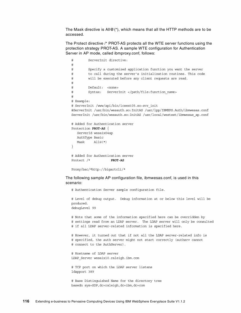
The Mask directive is All@(*), which means that all the HTTP methods are to be accessed.
The Protect directive /* PROT-AS protects all the WTE server functions using the protection strategy PROT-AS. A sample WTE configuration for Authentication Server in AP mode, called ibmproxy.conf, follows:
# ServerInit directive:## Specify a customized application function you want the server# to call during the server's initialization routines. This code# will be executed before any client requests are read.## Default: <none># Syntax: ServerInit </path/file:function_name>## Example:# ServerInit /www/api/bin/icsext05.so:svr_init#ServerInit /usr/bin/wesauth.so:InitAS /usr/lpp/IBMEPS.Auth/ibmwesas.confServerInit /usr/bin/wesauth.so:InitAS /usr/local/westest/ibmwesas_ap.conf
# Added for Authentication serverProtection PROT-AS {
ServerId wesaix04apAuthType BasicMask All@(*)
}
# Added for Authentication serverProtect /* PROT-AS
Proxy/bac/*http://bigartcli/*
The following sample AP configuration file, ibmwesas.conf, is used in this scenario:
# Authentication Server sample configuration file.
# Level of debug output. Debug information at or below this level will beproduced.debugLevel 99
# Note that some of the information specified here can be overridden by# settings read from an LDAP server. The LDAP server will only be consulted# if all LDAP server-related information is specified here.
# However, it turned out that if not all the LDAP server-related info is# specified, the auth server might not start correctly (authsrv cannot# connect to the AuthServer).
# Hostname of LDAP serverLDAP_Server wesaix10.raleigh.ibm.com
# TCP port on which the LDAP server listensldapport 389
# Base Distinguished Name for the directory treebasedn sys=SDP,dc=raleigh,dc=ibm,dc=com
116 Extending e-business to Pervasive Computing Devices Using IBM WebSphere Everyplace Suite V1.1.2

# LDAP userid to use for authentication with the LDAP serverLDAPAdmin cn=wesaix03,cn=wesadmin
# LDAP user's password in encrypted form (unencrypted password is"ldaper01")#ldappasswd x12u8cvQlNWLDAPPasswd 1mK7SGz5HVu
wepDN dc=wesaix03,dc=raleigh,dc=ibm,dc=com
command_port 9738
# Wireless Gateway trusted addresses. These are specified as a host IP# address and a subnet mask that is applied to that address.wlMni 10.10.20.1 255.255.255.0wlMni 10.10.30.1 255.255.255.0
# The shared secret used by RADIUSRADIUSSharedSecret 123456789
# Maximum number of times to attempt a RADIUS requestMaxRADIUSRetries 2
# Maximum amount of time to wait for a RADIUS request to complete, inmillisecondsMaxRADIUSTimeout 5000
# Maximum life of a session, in minutesMaxSessionAge 100
# Retry information for suspended authentication server, in secondsDefaultRetryDelay 80
# Authentication Server Role : "TransparentAuthenticationProxy" or"AuthenticationProxy"AuthServerRole AuthenticationProxy
# Hostname of primary and secondary RADIUS serversRADIUSServerP wesaix05.raleigh.ibm.com
# Hostname of primary and secondary AST serversASTServerP wesaix05.raleigh.ibm.com
# Maximum number of entries allowed in the session cache#MaxSessionCache 1000MaxSessionCache 0
# Interval for AST cleanup, in secondsASTCleanupInterval 300
# Default device type if no match found in LDAPdefault_device_type wireless#default_device_type palm
# Default network type. This is always used in WES Release 1.default_network_type GENERIC_WIRELESS
Chapter 6. User authentication 117

# Default username - used in case of trusted client address.# This must match the RADIUS username.#default_username test1@ibm## Is the @ibm necessary?default_username mountain
# Default password - used for testing until able to get remote_user and# password from WTE.default_password honeydew
6.2.3 Securing AP connectionsFor security reasons, trusted Wireless Gateway IP addresses or range of IP addresses, configured in the ibmwesas.conf file, should be filtered by the firewall in front of the Authentication Server.
In addition, HTTP connections with the Authentication Server can be secured using Secure Sockets Layer (SSL). SSL support is provided by WTE and the following connections can be secured:
HTTP client and WTE This is highly recommended to protect the password in HTTP basic authentication.
WTE to Web Server Optional.
Everyplace Wireless Gateway to WTE (and Authentication Server)Optional.
Other third-party gateway to WTE Optional.
For more information about where and how to enable Secure Sockets Layer (SSL), see Chapter 11, “Secure Sockets Layer (SSL)” on page 225.
6.2.4 Running the scenarioTo start the scenario, go to the URL http://wesaix03/bac/servlet/HelloWorldServlet.
Figure 78 shows the HTTP basic authentication prompt. The user name and password must correspond to a valid user previously enrolled using Tivoli Personalized Services Manager (TPSM). See Chapter 5, “End-user enrollment” on page 89 for details.
Figure 78. Log in using HTTP basic authentication
118 Extending e-business to Pervasive Computing Devices Using IBM WebSphere Everyplace Suite V1.1.2

Figure 79 illustrates the output of the HelloWorldServlet application. This is a servlet producing HTML content.
Figure 79. Accessing the Hello World sample servlet
Next we access another sample application using the URL http://wesaix03/bac/servlet/ServeXML_news. We do not get another authentication window because WES keeps track of the active session for the specific user using the Application Session Table (AST).
Figure 80 illustrates the first part of the sample application. The application content for the welcome window is HTML.
The entered user name must be in the form user@realm, even if you are only using a single realm.
Note
Chapter 6. User authentication 119

Figure 80. News application - welcome window
Next we click click here to access the news content in XML.
Figure 81 shows a warning message. Since the second part of the application generates XML and we have not included the transcoding proxy in this scenario, the Netscape browser interprets the results as an error.
Figure 81. Netscape warning message
120 Extending e-business to Pervasive Computing Devices Using IBM WebSphere Everyplace Suite V1.1.2

By opening the file, we can use Internet Explorer to display the XML file as shown in Figure 82.
Figure 82. Sample application XML content
An alternative is to use Internet Explorer XML support and use style sheets to display the results. However, in this redbook we want to show how this application can be accessed from any browser or mini-browser using transcoding to convert to XML to other markup languages such as HTML and WML. This will be shown later in Chapter 7, “Transcoding” on page 129.
6.3 Sample scenario: Transparent Authentication Proxy (TP)
Access to materials outside of the WES domain(for example Internet access) is provided in the WebSphere Everyplace Suite environment when you install and configure the Authentication Server component as a Transparent Authentication Proxy (TP). In this section we describe this option and provide a sample configuration.
A Transparent Authentication Proxy also performs user authentication based on HTTP authentication headers. However, the Transparent Authentication Proxy allows other Suite components, such as content and application servers, to do their own user authentication.
On the other hand, when the Authentication Server is configured as a Transparent Authentication Proxy, users have to explicitly use an HTTP proxy, such as proxy.wes.com (see Figure 83) to access services within or outside the domain hosted by the WebSphere Everyplace Suite.
Chapter 6. User authentication 121

In this scenario, users trying to access services outside the WES domain, such as service hosted by www.internet.com, can do so through the Transparent Authentication Proxy.
Figure 83. Sample Authentication Proxy and Transparent Authentication Proxy for Internet access
In order for clients to access both Internet services and services hosted by the WebSphere Everyplace Suite, the Everyplace Authentication Server can be configured in the way illustrated in Figure 83. In this case, a client can send one of three requests: wesA for service A hosted by the WebSphere Everyplace Suite, wesB for service B hosted by the WebSphere Everyplace Suite, and Internet Web requests (for example, from .com sites).
Since Internet requests must be supported, an Everyplace Authentication Server acting as a Transparent Authentication Proxy is used, denoted as proxy.wes.com in Figure 83. For the services hosted by the WebSphere Everyplace Suite domain, a second Everyplace Authentication Server, acting in Authentication Proxy mode, is used as the next hop after the Transparent Authentication Proxy.
Notice that only the Authentication Proxy uses the Proxy directive, which defines the next hop routing from the Authentication Proxy. The Transparent Authentication Proxy does not use the Proxy directive.
Also notice that both Authentication Servers use the Protect directive. This is how WES implemented the single sign-on.
6.3.1 Transparent Proxy (TP)This scenario is an example of an enterprise that allows certain users to access the Internet and internal (intranet) applications. These users have a user ID and a password (for details, see Chapter 5, “End-user enrollment” on page 89). Other
This configuration enables passthrough of Internet-destined traffic and enables secure connections to Internet sites using SSL tunneling.
Note
122 Extending e-business to Pervasive Computing Devices Using IBM WebSphere Everyplace Suite V1.1.2

users without user ID and password are not allowed to access the Internet or internal applications.
The authentication is performed at the TP Authentication Server that routes the request to the internal application, via the AP Authentication Server, or to the Internet according to the specified URL.
Figure 84. Using a WES Authentication Server as a Transparent Proxy (TP)
6.3.2 Transparent Proxy (TP) configurationIn this scenario the Authentication Server in TP is started with the following command:
ibmproxy -p 8005 -debug -mtv -r /usr/local/westest/ibmproxy_tp.conf
This gives us the port number that the proxy server is using for incoming requests and the path of the ibmproxy.conf file in use. In our case, the port number is 8005 and the path and file name is /usr/local/westest/ibmproxy_tp.conf.
The following is in the ibmproxy.conf file:
# ServerInit directive:## Specify a customized application function you want the server# to call during the server's initialization routines. This code# will be executed before any client requests are read.## Default: <none># Syntax: ServerInit </path/file:function_name>## Example:# ServerInit /www/api/bin/icsext05.so:svr_initServerInit /usr/bin/wesauth.so:InitAS /usr/local/westest/ibmwesas_tp.conf
Chapter 6. User authentication 123

Protection TransProxy {ServerID wesaix04_tpAuthtype BasicMASK All@(*)
}Protect * TransProxy
# TransparentProxy directive:## Specifies if the server is to be run as a transparent proxy server.## Default: off# Syntax: TransparentProxy <on | off>TransparentProxy off
Note: Do not be confused!. The TransparentProxy directive (off in this scenario) does not refer to the Authentication Server function. This is related to the WebSphere Traffic Express (WTE) configured as a Transparent Proxy. Unfortunately the same name is used in both cases.
The following Authentication Server configuration file, ibmwesas.conf, is used in this scenario:
# Authentication Server sample configuration file.
# Level of debug output. Debug information at or below this level will beproduced.debugLevel 99
# Note that some of the information specified here can be overridden by# settings read from an LDAP server. The LDAP server will only be consulted# if all LDAP server-related information is specified here.
# Hostname of LDAP serverLDAP_Server wesaix10
# TCP port on which the LDAP server listensldapport 389
# Base Distinguished Name for the directory treebasedn sys=SDP,dc=raleigh,dc=ibm,dc=com
# LDAP userid to use for authentication with the LDAP serverLDAPAdmin cn=wesaix04,cn=wesadmin
# LDAP user's password in encrypted form (unencrypted password is "ldaper01")LDAPPasswd igrfDTgpHnC
wepDN dc=wesaix04,dc=raleigh,dc=ibm,dc=com
gatewayDN cn=weshack
#command_port 9736
# Wireless Gateway trusted addresses. These are specified as a host IP
124 Extending e-business to Pervasive Computing Devices Using IBM WebSphere Everyplace Suite V1.1.2
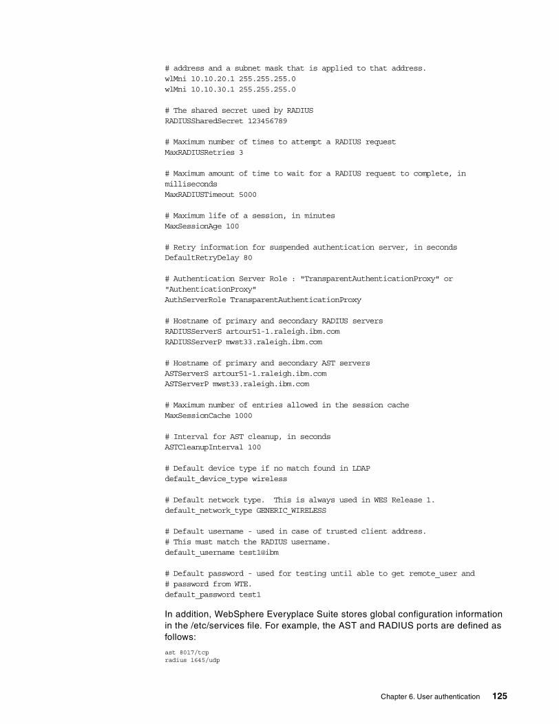
# address and a subnet mask that is applied to that address.wlMni 10.10.20.1 255.255.255.0wlMni 10.10.30.1 255.255.255.0
# The shared secret used by RADIUSRADIUSSharedSecret 123456789
# Maximum number of times to attempt a RADIUS requestMaxRADIUSRetries 3
# Maximum amount of time to wait for a RADIUS request to complete, inmillisecondsMaxRADIUSTimeout 5000
# Maximum life of a session, in minutesMaxSessionAge 100
# Retry information for suspended authentication server, in secondsDefaultRetryDelay 80
# Authentication Server Role : "TransparentAuthenticationProxy" or"AuthenticationProxy"AuthServerRole TransparentAuthenticationProxy
# Hostname of primary and secondary RADIUS serversRADIUSServerS artour51-1.raleigh.ibm.comRADIUSServerP mwst33.raleigh.ibm.com
# Hostname of primary and secondary AST serversASTServerS artour51-1.raleigh.ibm.comASTServerP mwst33.raleigh.ibm.com
# Maximum number of entries allowed in the session cacheMaxSessionCache 1000
# Interval for AST cleanup, in secondsASTCleanupInterval 100
# Default device type if no match found in LDAPdefault_device_type wireless
# Default network type. This is always used in WES Release 1.default_network_type GENERIC_WIRELESS
# Default username - used in case of trusted client address.# This must match the RADIUS username.default_username test1@ibm
# Default password - used for testing until able to get remote_user and# password from WTE.default_password test1
In addition, WebSphere Everyplace Suite stores global configuration information in the /etc/services file. For example, the AST and RADIUS ports are defined as follows:
ast 8017/tcpradius 1645/udp
Chapter 6. User authentication 125

That is, in this scenario port 8017 is used for communications with the AST server using the TCP protocol, and port 1645 is used for RADIUS server authentication requests via UDP.
6.3.3 Client configurationOn the client machine, you need to set the device to use an HTTP Proxy. As we are using Netscape Navigator Version 4.5, the direct proxy configuration is set in the Manual Proxy Configuration window, shown in Figure 85.
Notice that the TP is listening on port 8005 for incoming HTTP requests in this scenario.
For client devices that do not support a proxy configuration, this support is typically provided by a gateway.
Figure 85. Netscape browser proxy configuration
Once you have entered the address of the Transparent Proxy and the port number, click OK to activate the changes.
6.3.4 Running the scenarioFor example, a user wants to access the Web server at www.ibm.com. Then, the URL points to a server location outside the WES domain, http://www.ibm.com. In a similar way, to access applications in the WES domain, the requests flow through the Authentication Server configured in AP mode as shown in the previous scenario (see 6.2, “Sample scenario: Authentication Proxy (AP)” on page 113.
126 Extending e-business to Pervasive Computing Devices Using IBM WebSphere Everyplace Suite V1.1.2

The first window is the HTTP authentication prompt, shown in Figure 86. A valid user name must be entered in the format of user@realm, even if only a single realm is used.
Figure 86. Authentication Server Transparent Proxy (TP) login
Notice the name of the server comes from the Protection directive in the ibmproxy.conf configuration file (wesaix04_tp) as well as the Authentication Server name and listening port number used in this scenario (wesaix04.raleigh.ibm.com:8005).
After a successful authentication, access to the Internet is allowed by the Authentication Server wesaix04.raleigh.ibm.com. The result is illustrated in Figure 87.
Chapter 6. User authentication 127

Figure 87. Accessing materials outside the WES domain
128 Extending e-business to Pervasive Computing Devices Using IBM WebSphere Everyplace Suite V1.1.2

Chapter 7. Transcoding
IBM WebSphere Everyplace Suite Version 1.1.2 includes the IBM WebSphere Transcoding Publisher (WTP) Version 1.1.2 product with additional support for proper integration with WES. Although WTP supports other operational models (servlets and Java Beans), only the network proxy model is available in Everyplace Suite Version 1.1.2.
In this chapter we describe a sample scenario running with IBM WebSphere Transcoding Publisher using the stand-alone proxy model.
7.1 Overview
In a typical Web environment, information is simply sent from a server to a browser for display and interaction. However, there are many ways that adding an intermediary between the browser and the server can improve the system. For example, an intermediary can keep track of the information the user has viewed in order to make it easier to find information again. Also, an intermediary may enhance the information that the user sees by adding annotations and personalization beyond what the server was designed to do. Intermediaries turn the network into a “smart pipe” with applications that can enhance the information on the Web.
With this option, WebSphere Transcoding Publisher sits between the client and any Web server that can be reached by the client. If required, a firewall can be deployed between the client and the Web server, as shown in Figure 88.
Figure 88. Transcoding Publisher running as network proxy in WES environment
In the emerging pervasive marketplace, you have a wide variety of devices attempting to access data on the Internet and within enterprise systems. It should be noted that there is a complex underlying structure of wired and wireless gateways at play in this environment. However, above the base level of getting connected is the flow of HTTP requests. In the basic transcoding model, these requests flow from the client device to a proxy server.
© Copyright IBM Corp. 2001 129

The transcoding framework also allows industry-standard servlets to be incorporated as transcoders. Servlets written for other environments can be easily ported to run in the proxy server, and new plug-ins written to the Java Servlet API will be usable in the many Web servers that support servlets. The transcoding proxy supports Version 2.1 of the Sun Java Servlet API. Servlets written to this API should run with few or no changes in the transcoding framework.
Transcoding Publisher is network software that modifies content presented to users based on the information associated with the request, such as device constraints, network constraints, and organizational policies. This transformation of information from one form to another is the central idea behind transcoding, a technology particularly suited to bridging the gaps between the variety of data formats encountered on the Web.
Transcoding Publisher uses specialized programs called transcoders to perform different conversions. Typical conversions performed by the transcoders supplied with Transcoding Publisher include:
• Converting XML documents from one form of XML to another through the use of style sheets.
Note: Style sheets can be applied dynamically to XML content to customize the format and layout of output content.
• Simplifying HTML documents with a number of customizations, such as removing objects or features not supported on the target device (such as JavaScript) or converting tables to lists.
• Manipulating images to affect scaling, compression, color depth, and format.
7.2 Basic flow for Transcoding Publisher acting as a proxy
The basic flow for Transcoding Publisher acting as a network intermediary (transcoding proxy) is shown in Figure 89.
Figure 89. WTP proxy basic flow - HTTP and WAP (Path 1 and Path 2)
130 Extending e-business to Pervasive Computing Devices Using IBM WebSphere Everyplace Suite V1.1.2

In the diagram shown in Figure 89, the arrows indicate the flow of information to and from the transcoding proxy. The flows are numbered to show different paths through the transcoding proxy as follows:
Path 1 in Figure 89 shows the transcoding proxy acting on behalf of an HTTP-based client browser that expects HTML or XML pages in return.
1. The client browser sends an HTTP request to the transcoding proxy. The request can be for any Web documents, including HTML pages, XML pages, or GIF or JPEG images.
2. The transcoding proxy can edit the request to modify the URL or to change values in the header fields. It then sends the HTTP request to the Web server to acquire the requested object. The proxy also saves information from the request that identifies the device making the request.
3. The Web server returns the page requested by the transcoding proxy on behalf of the client.
4. The transcoding proxy uses information from the request and response along with rules in the Preference Aggregator to identify the device, user, and network profiles needed to control the way the document is transcoded. When particular transcoding modules running in the transcoding proxy request the values of particular preferences or constraints, the Preference Aggregator uses the profile identification information in evaluating its rules to help determine the correct value to return. Using these preference and constraint values, the transcoding proxy edits the response received from the Web server, tailoring it for the client device before returning it to the client in an HTTP reply.
Path 2 in Figure 89 shows the transcoding proxy acting on behalf of a Wireless Application Protocol (WAP) client, such as a smart phone.
1. The wireless client sends a WAP request that is converted to an HTTP request by the WAP gateway. The WAP gateway forwards the HTTP request to the transcoding proxy.
2. The transcoding proxy sends the HTTP request to the Web server after any necessary editing.
3. The HTTP reply comes back from the Web server.
4. When the transcoding proxy matches information from the request against device and user profiles, it discovers that the device requires Wireless Markup Language (WML) output. For this example, assume the original document was an XML document. The transcoding proxy uses the preference information to select the correct style sheet to convert the document to its WML form. Then it returns the response to the WAP gateway, which converts the text-based WML documents to the compressed wireless-ready form before sending it to the client smart phone.
7.3 WES Authentication Server and Transcoding
In many cases we need to configure the Everyplace Authentication Server in front of the IBM WebSphere Transcoding Publisher to support client devices that require certain types of transcoding. As displayed in Figure 90 on page 132, the IBM WebSphere Transcoding Publisher server is denoted as A.wes.com and
Chapter 7. Transcoding 131

services X and Y require transcoding before they can be presented to client devices.
The Authentication Server shown in Figure 90 is configured in AP mode; therefore, it is defined as a reverse proxy. Client devices will not be configured an HTTP proxy and the server name in the URL must indicate the name of the AP proxy (wes.com). The Authentication Server uses its configuration file (ibmproxy.conf) to map URL aliases into target application server names. It also uses the http_proxy directive to forward the request to WTP (A.wes.com). Notice that the no_proxy directive overrides this proxy option by indicating that the proxy (WTP in A.wes.com) should be bypassed.
This mechanism allows you to use the WTP proxy for selected application servers only, as illustrated in Figure 90.
Figure 90. Transcoding application content in a WES environment
7.4 Configuration
This section describes the configuration of the Transcoding Publisher as a network stand-alone proxy.
7.4.1 Port mappingIf you are using Transcoding Publisher as a network proxy, you must enter the port numbers on which Transcoding Publisher will listen for traffic. There are three network preference profiles provided when you finish WTP as a proxy configuration. You can change the port associated with each of these profiles manually or you can use the Administration Console. By default the following ports are used:
• Port 8089 for wireless networks • Port 8088 for network default • Port 8090 for dial network
132 Extending e-business to Pervasive Computing Devices Using IBM WebSphere Everyplace Suite V1.1.2

Note: WTP uses these ports to assign traffic priorities.
Even if you are not adding any network preference profiles, you should review the default port settings for the network preference profiles provided with Transcoding Publisher to ensure that they do not conflict with existing port settings on your system. If there is a conflict, you can use the Proxy Port Settings window to change the port settings for the networks, or if there is a network type you do not use, you can disable that network preference profile. If you don't want to differentiate between network types, specify the same port number for all types. The port numbers must be either all the same or all different.
To open the Proxy Port Settings window (Figure 91), click File -> Settings -> Proxy Port on the Administration Console.
Figure 91. WebSphere Transcoding Publisher port mapping
The window shown in Figure 91 will show only the ports for enabled profiles. If you disable one of the profiles on the Administration Console, you will not be able to see the port associated with it, but it will keep the configuration for that profile, including the port number. It will also show you the port for any enabled configuration that you have created using the WTP toolkit and registered using the WTP Administration Console.
7.4.2 Using a caching proxyUsing a caching proxy to cache transcoded pages is an option when using WebSphere Transcoding Publisher. For details see Chapter 8, “Caching transcoded pages” on page 161.
7.4.3 Firewall configurationIf you have a firewall to protect your network from the Internet, you must select the type of connection by which to access a Web server on the Internet. It can be
Do not delete a profile from the Administration Console. If you don’t want to use it, just disable it. Otherwise, the file with all the information for that profile will be physically deleted from your computer.
Note
Chapter 7. Transcoding 133

a SOCKS or a proxy configuration. Contact your network administrator to help you obtain the actual configuration.
To change your firewall configuration, click File -> Settings -> Firewall on the Administration Console window. This will display Figure 92.
Figure 92. Firewall settings
In this window you specify the service that is being used on the firewall (proxy or SOCKS) with the associated port. You can also include the addresses for which the firewall will not be used.
7.5 Transcoding tools
The Developer’s Toolkit provided by WTP is intended for device manufacturers, ISVs, and service people who want to extend the existing behavior of IBM WebSphere Transcoding Publisher by using the provided tools and APIs. These tools help you use and develop extensions to Transcoding Publisher.
WTP provides the following tools:
• Request Viewer • Transform Tool • Snoop Tool • Creating preference profiles • Creating new transcoders
In this section we describe two very important tools, the Request Viewer and the Transform Tool. For information about creating new preference profiles, new WTP transcoders and other tools, see the redbook IBM WebSphere Transcoding Publisher V1.1 Extending Web Applications to the Pervasive World, SG24-5965.
7.5.1 Request ViewerThe Request Viewer is a visual tool for monitoring the operation of the transcoding server. You can view which monitor-editor-generator (MEG) groups
134 Extending e-business to Pervasive Computing Devices Using IBM WebSphere Everyplace Suite V1.1.2

and MEGlets are registered with the transcoding server, along with the configuration information for the plug-ins. The Request Viewer is particularly useful as a debugging tool, as it enables you to monitor the flow of requests through the server and observe which plug-ins are triggered and when they are triggered. For each transaction, the Request Viewer also displays the header and content information as they are manipulated by the plug-ins.
To start the Request Viewer on a transcoding AIX system, issue the following command from the IBMTrans directory:
./RunTranscoding.sh -g
The -g switch indicates to the shell script to start the WTP proxy and the Request Viewer console.
We recommend that you always use the Request Viewer tool to start WTP as a proxy server during testing and problem determination. However, during production you should start WTP without the Request Viewer for performance reasons.
The Request Viewer provides two views of the transcoding server:
• Server Configuration is a view of the transcoding server's configuration of registered sublayers, plug-ins, and MEGs, and the transcoding server's tracing information and messages.
• Request Processing is a dynamic view of the flow of requests through the transcoding server and the transcoding processes for each request.
In the Request Viewer, you can:
• Clear the message area • Clear the request display areas • Define the amount of displayed message information • Define the amount of displayed request information • Define the amount of displayed trace information • Display the Transcoding Publisher version number • Display pending requests • Display request processing information • Start displaying request processing information • Stop displaying request processing information • Stop the Request Viewer
You can use this tool to make sure that Transcoding Publisher is successfully running as a proxy. You can also monitor the traffic to verify that the information is being transcoded, as shown by the messages in Figure 93.
The Request Viewer tool starts WTP as a transcoding proxy with additional logging and trace facilities for debugging and problem determination.
Note
Chapter 7. Transcoding 135

Figure 93. Request Viewer output messages - Server Configuration tab
Figure 94 shows information for a request to WTP (Request Processing tab).
Figure 94. Request viewer - Request Processing tab
This tool is very useful, but you have to be careful to use tracing and messaging. Use this facility only when needed, because it will make your proxy run slowly.
136 Extending e-business to Pervasive Computing Devices Using IBM WebSphere Everyplace Suite V1.1.2

7.5.1.1 Server Configuration view The Server Configuration view (shown in Figure 93 on page 136) shows the current state of the IBM WebSphere Transcoding Publisher server. The tree view, displayed under Server Configuration, lists the components of the transcoding server. Transcoding server components are grouped as sublayers and plug-ins:
• Sublayers
The sublayers node contains information about the currently loaded sublayers. Sublayers are protocol specific. In most cases, you will see only information about the HTTP sublayer, such as ibm/HttpSublayer (8090, 8089, 8088), “plugged-in”.
• Plug-ins
The Plug-ins node contains information for all registered plug-ins and the MEGs contained in a plug-in. Below each plug-in listed in the tree, all of its associated MEGs are represented by individual nodes:
• Request editor • Generator • Editor • Monitor
The details shown for plug-ins are:
• The name of the plug-in • The state of the plug-in (loaded and enabled, etc.) • Number of MEGs • List of MEGs
The details shown for MEGs are:
• The name of the MEG • MEG type • Condition • Priority • State
7.5.1.2 Request Processing viewThe Request Processing view shows the flow of requests through the transcoding server and the invocation and the execution of the plug-ins and their associated MEGs as the request is processed.
The tree view, displayed under Request Processing, groups each request and the MEGs that are used to process this request. For each MEG the input and output information is also available. When transaction tracing is enabled the Request Processing view displays information about the individual transactions in a tree in the left pane.
As the transaction is being processed, MEGs change the header and the content, and header information displays in the Transaction Header pane. The data
The Request Viewer tool is intended to be used for development only. It is not designed and should not be used in a production environment.
Note
Chapter 7. Transcoding 137

displays in the Transaction Content pane. This data is in either binary or text formatm depending on the type of transcoding that is being performed.
7.5.1.3 Other functions in Request ViewerThere are a few other functions we need to be aware of when we use Request Viewer. These are invoked using the following pull-down menus:
• File • Actions • Requests • Help
Basically, the functions above are for tracing and debugging, for messages and clearing the message area and request processing views. You can also copy the text area to another file for editing.
Figure 95 shows the Request Viewer menu bar options. Select the Clear Output - Messages option to reset the text area.
Figure 95. Request Viewer - File options
Figure 96 shows how to choose the displayable content length.
Figure 96. Request Viewer functions for the requests
Since Request Viewer does not support copy and paste from the menu bar, you need to use the Ctrl+C and Ctrl+V keys.
Note
138 Extending e-business to Pervasive Computing Devices Using IBM WebSphere Everyplace Suite V1.1.2

As illustrated in Figure 97, the messaging options are: No Messages, All Messages, Errors, Warnings and Informational.
Figure 97. Request Viewer - Messaging options
As shown in Figure 98, the trace options are: No tracing, All Tracing, Error Exceptions and MEG Routing
Figure 98. Request Viewer - Trace options
The results are shown in the Output - Messages pane (see Figure 99). To see the results you need to select the Server Configuration view.
Figure 99. Output Messages pane showing all messages
When you want to see all requests in the Request Processing view you have to select Request Tracing enabled (see Figure 96 on page 138). You can also stop the tracing by unchecking this check box.
Figure 100 shows a sample of the Output- Messages pane after using a WAP device to request www.ibm.com.
Chapter 7. Transcoding 139

Figure 100. Output messages showing one card for WML transcoding
The Request Viewer can be used as an overall tool to learn how IBM WebSphere Transcoding Publisher works, or you can use it for problem determination and also searching for bottlenecks in the system.
Also, if you make changes (for example, to a preference profile) through the Administrator's Console, the Refresh Server function will not update the Transcoding Publisher server. If you want changes made in this way to take effect, you must restart the Transcoding Publisher server.
7.5.2 The Transform ToolThe Transform Tool allows you to view the transcoded results for specific images and documents that you load. The tool does not require WTP running, but it will use and invoke the preference profiles, transcoders, and registered style sheets from the configuration files.
By placing original content and transcoded content side by side, the Transform Tool demonstrates how a particular image or document will be affected by Transcoding Publisher‘s current settings.
For example, Figure 101 shows how an original image (in the left pane) would appear after being transcoded (in the right pane) and displayed on a Palm Pilot device running the HandWeb browser.
140 Extending e-business to Pervasive Computing Devices Using IBM WebSphere Everyplace Suite V1.1.2

Figure 101. Transform Tool showing a transcoded image
7.5.2.1 Using the Transform ToolStart the tool by issuing the ./TransformTool.sh command from the IBMTrans directory. To perform transcoding operations with the Transform Tool, you can do the following:
1. Select the content to be transcoded by choosing an option from the File pull-down menu. The Transform Tool enables you to choose from three kinds of data (see Figure 102):
• Load Image enables you to select a GIF or JPEG image.
• Load HTML enables you to select an HTML document.
• Load XML enables you to select an XML document.
When you have selected the file, its contents will be displayed in the left pane. Although images are rendered as such in the Transform Tool, HTML and XML documents are displayed in their source format, rather than as they might be formatted by a browser.
The Transform Tool bases its transcoding operations on the settings specified in the Transcoding Publisher preference profiles.
Note
Chapter 7. Transcoding 141

Figure 102. Image loaded and transcoded (image reduction) in the Transform Tool
2. Select a Target Device from the drop-down box. For example:
• Internet Explorer 5.0 • Hand Held Windows CE • Palm Pilot HandWeb • WML WAP Phone
3. Select File -> Transcode to start the transcoding operation. The transcoded data will be displayed in the right pane. As with the untranscoded content, images are rendered appropriately, and HTML and XML output is shown in its source format.
4. To keep the transcoded output for later use, select File -> Save -> Transcoded Content.
5. Select File -> Exit to close the tool.
Figure 103 shows sample HTML content transcoded to WML.
142 Extending e-business to Pervasive Computing Devices Using IBM WebSphere Everyplace Suite V1.1.2

Figure 103. HTML content transcoded for WML WAP phone
Figure 104 shows a sample XML content transcoded to WML.
Figure 104. XML content transcoded for Palm Pilot HandWeb
Chapter 7. Transcoding 143

7.5.3 Using XML style sheets with the Transform ToolTranscoding Publisher includes several sample XML style sheets you can use with the Transform Tool to observe how data can be transcoded from XML to HTML and other varieties of XML, such as WML. However, when using the Transform Tool to convert XML data through the use of style sheets, you must ensure that each required style sheet has been registered with Transcoding Publisher prior to starting the Transform Tool.
To register the XML style sheets, do the following:
1. Start the Administration Console.
2. For each XML style sheet you want to register, select a folder in which to store the style sheet (such as the XML Stylesheet Selectors folder) and then click Register -> XML Stylesheet to start the registration wizard. More detailed instructions for using the console are available from the online help.
3. The following information should be specified in the appropriate places in the wizard:
• Location: The sample files are located in the toolkit style sheets samples directory under the Transcoding Publisher installation directory. There is a sample file for each device type supported by the Transform Tool. A sample XML source document is also provided.
• Output content type: Specify the proper output content for each style sheet, for example text/html for HTML or text/vnd.wap.wml for WML.
• Input DTD: Specify the DTD if any or leave blank if not used.
For more detailed instructions about registering and using style sheets, see 7.6.2.1, “Registering style sheets” on page 148.
4. Update the transcoding server by selecting File -> Refresh Server.
5. Exit the Administration Console and start the Transform Tool.
Figure 105 shows an XML document transcoded to HTML for a Netscape browser and using Network Default as the target network. The XML document is the sample FlightInfo.xml file and the registered style sheet is also the sample FlightInfoForNet_IE.xsl file.
If you try to transcode an XML file without registering the associated style sheet, the XML document will not be transcoded. You will need to register the style sheet for proper operation.
Note
144 Extending e-business to Pervasive Computing Devices Using IBM WebSphere Everyplace Suite V1.1.2

Figure 105. Sample transcoded XML (FlightInfo.xml) after registering the style sheet
7.6 Sample scenario
In this section, we present a sample scenario that shows how you can deploy a WebSphere Transcoding Publisher (WTP) proxy in the WES environment. In this scenario, the WTP proxy transcodes application content (HTML and XML) from our sample WebSphere Application Server (WAS) applications. However, other Web applications not using WAS can also be transcoded.
Figure 106 illustrates the scenario as follows:
• Two client devices, a desktop and a WAP simulator, are connected to the WES Authentication Server via HTTP.
• The Authentication Server installed in AP mode (Authentication Proxy) and configured as a reverse proxy.
Figure 106. Sample scenario: adding a Transcoding Proxy to a WES environment
Chapter 7. Transcoding 145

7.6.1 Proxy configuration in the Authentication Server When running the Authentication Server in AP mode, you need to create two proxy statements in the ibmproxy.conf file that tell the Edge Server - Caching Proxy used by the Authentication Server that the request will use a proxy (transcoding proxy in this case) after it goes through the Authentication Server. The directives in WTE configuration file are:
• The http_proxy directive is used for requests that pass through the proxy and specifies the host name of the (transcoding) proxy instance that is used as the default Everyplace Suite domain transcoding proxy.
• The no_proxy directive is used for requests that do not pass through the (transcoding) proxy, for example TPSM Device Manager traffic. The no_proxy directive specifies the domains to which the server should directly connect. This directive does not apply when the proxy goes through a SOCKS server; use socks.conf for that purpose. Also, if you are using neither proxy chaining nor SOCKS, then this directive is not needed.
Next we configure the ibmproxy.conf file on the WTE, where the WES Authentication Server is running as a plug-in, to have the WTP act as a proxy server.
In this configuration, the Authentication Server proxy accepts client requests, then routes those requests to the http_proxy (the transcoding proxy), and then the request will go to the application content server.
The http_proxy directive is used to specify the name of another proxy Web server. This server should be contacted for HTTP requests rather than contacting the HTTP Server named in the request URL directly.
In our scenario, we specified the transcoding proxy to be:
http_proxy http://wesaix02.raleigh.ibm.com:8089/
Our request will go to the Authentication Server, wesaix03, then to the http_proxy pointed to by the http_proxy directive in the configuration file, wesaix02, and then it will go to the application server pointed by the alias bac in the configuration file, http://bigartcli/*, and access the application in /servlet/ServeXML_news, where “servlet” is the alias used for default WAS servlets.
In this scenario the WTP proxy is listening on ports 8088, 8089 and 8090 but Authentication Server is sending the HTTP traffic to port 8089 as configured in the http_proxy directive.
7.6.2 Using the WTP Administration ConsoleTo start the Administration Console, on the transcoding AIX system issue the following command from the IBMTrans directory:
./AdminConsole.sh
The Authentication Proxy (AP) appears to the client to be the application content server, and the client is not aware that the request has been sent to another server.
Note
146 Extending e-business to Pervasive Computing Devices Using IBM WebSphere Everyplace Suite V1.1.2

The main window of the Administration Console has two sections. The left side shows a tree view of three types of resources: preference profiles, transcoders, and style sheet selectors. Each preference profile, transcoder, and style sheet selector is shown with a colored icon. Resources that have been disabled are shown with an icon with a red X in a white box.
In addition to working with resources through the tree view, you can perform several tasks using menu items. As illustrated in Figure 107, the menus available are File, Register, Logs, and Help.
Figure 107. WTP Administration Console
From the File menu, you can:
• Create a new folder to organize style sheets
• Move a style sheet or folder in the tree
• Save your work when modifying a resource
• Delete the selected resource or folder
• View and modify settings for the firewall server, proxy ports, cache, or server setup
• Refresh the server so that it will recognize and use changes that you have made to resources, settings, or logging and tracing
• Exit the Administration Console
You can use the Register menu items to extend Transcoding Publisher's functionality. You can register a new style sheet, transcoder, or preference profile, making it available for Transcoding Publisher to use.
From the Logs menu, you can:
• Enable or disable tracing or message logging
• Modify properties of tracing or message logging
• View the current trace or message log files
From the Help menu you can view:
• The Help window
• The Administrator's Guide, which provides more detailed information
• The About this product window
• The Help table of contents
Chapter 7. Transcoding 147

You can also access the product support Web site from the Help menu.
7.6.2.1 Registering style sheetsIn order for our XML application to be displayed correctly on our chosen clients, we need to register appropriate XSL style sheets using the WebSphere Transcoding Publisher’s Administrative Console.
We will now walk through an example registration of the style sheet used to transcode XML to HTML.
To begin, from the Administration Console menu bar click Register -> XML Stylesheet. Figure 108 shows the welcome window for the style sheet registration wizard.
Figure 108. Welcome window of the XML style sheet wizard in WTP administration
We now define the XSL style sheet to WTP and its appropriate output as shown in Figure 109. By specifying the output, the Transcoder will use this style sheet when transcoding XML to HTML content.
148 Extending e-business to Pervasive Computing Devices Using IBM WebSphere Everyplace Suite V1.1.2

Figure 109. Specifying the style sheet location and output content
In our scenario, we select the Browse option to locate the path and name of the style sheet (for example, MainNewsFeed_new.xsl).
As shown in Figure 110, we now label our style sheet. Notice that spaces are not allowed in the style sheet name. We also provide an informative description.
Figure 110. Name of style sheet and description
Chapter 7. Transcoding 149

Our XML application content does not specify a DTD so we leave it blank (see Figure 111). If using DTDs, you can specify additional criteria for selecting the proper style sheet.
Figure 111. Specifying DTDs using the style sheet registration wizard
We then choose to enable our style sheet immediately, as shown in Figure 112. Additional criteria, for example key/value pairs, can also be defined for more specific style sheet selection criteria.
Figure 112. Enabling a new style sheet in the registration wizard
150 Extending e-business to Pervasive Computing Devices Using IBM WebSphere Everyplace Suite V1.1.2

We repeat a similar process for the XML-to-WML style sheet to support WAP phones.
Figure 113. Location and output format of the WML style sheet
Figure 114. Name and description of the WML style sheet
Figure 115 and Figure 116 are the properties windows for the two style sheets we registered. Any changes here must be made by clicking Save and then refreshing the server by clicking File -> Refresh Server.
Chapter 7. Transcoding 151

Figure 115. XML style sheet selection for desktop browsers (HTML format)
Figure 116. XML style sheet selection for WAP phones (WML format)
From the Properties window, you can modify the properties of a style sheet selector, which defines criteria used to select a style sheet to be applied to an XML document. When you select a style sheet selector from the tree or from a list, the name and description will be displayed. You can modify the name and description to make them useful to you.
To identify the file location for the style sheet, for example, type a file location relative to /etc/stylesheets. You can also use the Browse button to locate the style sheet file.
152 Extending e-business to Pervasive Computing Devices Using IBM WebSphere Everyplace Suite V1.1.2

After a style sheet has been registered, it must be enabled for Transcoding Publisher to use it. Select the Enabled check box to specify whether this style sheet selector should be used by Transcoding Publisher or not.
The selection criteria defined for this style sheet will determine the XML documents for which this style sheet will be used. Each style sheet must have a different set of selection criteria. A style sheet will be selected only if all of the selection criteria defined for it are true. If there are two or more style sheets whose document-related criteria are all satisfied by a particular XML document, a style sheet may be chosen by its association with preference profiles in effect when the document is processed.
Each style sheet selector must include the one required selection criterion, which is the output content type. Choose the correct output content type from the drop-down list or type a value in the entry box.
You can also specify optional selection criteria. Two of the most commonly used criteria can be specified in this window:
• Specify the file location or URL for the input DTD (document type definition). You can use the Browse button or type the file location or URL, or a string that matches the name following the DOCTYPE keyword in the DTD. This style sheet will be used only for XML documents that specify this same input DTD.
• If the output type is text/xml, you can enter the name of the output DTD, or a string that matches the name following the DOCTYPE keyword in the DTD. This style sheet will be used only for XML documents that specify this same output DTD.
If required, click the Advanced button (see Figure 116) for additional selection criteria.
7.6.2.2 WebSphere Application Server and IBM HTTP ServerNo special configurations are necessary for our application server or our IBM HTTP Server. Our servlet ServeXML_news should be placed in the /servlets directory of the WebSphere Application Server. See Chapter 4, “WebSphere Everyplace Suite sample scenario” on page 71 for instructions on servlet usage and the placement of the XML files.
7.6.3 Running the WAS application from a Web browserin AP mode, the Authentication Server is set up as a reverse proxy and we use the WebSphere Transcoding Publisher as a proxy for transcoding.
To start the scenario, we go to http://wesaix03/bac/servlet/HelloWorldServlet, where:
• wesaix03 is the Authentication Server in AP mode as reverse proxy.
• bac is the directive in WTE ibmproxy.conf file. It specifies the target application server for this alias. For example in our scenario:
Proxy /bac/* http://bigartcli/*
• servlet is the default alias in WebSphere Application Server where the servlet HelloWorldServlet is located.
• In addition, the http_proxy directive in the ibmproxy.conf file in WTE points to the WTP proxy (wesaix02) as follows:
Chapter 7. Transcoding 153

http_proxy http://wesaix02.raleigh.ibm.com:8089/
Note: In this scenario we selected to use port 8089 (wireless network) in the WTP proxy. However, it will be up to you to decide the proper ports in WTP proxy. See 7.4.1, “Port mapping” on page 132 for details.
Figure 117 shows the authentication prompt. This is the HTTP Basic Authentication window. The User Name and Password must correspond to a valid user previously enrolled using Tivoli Personalized Services Manager (TPSM).
Figure 117. HTTP Basic Authentication
Note: In this release you must specify a realm in the User Name box. Even if you are only using one realm, it must be specified. Therefore, the user name you enter must be of the form user@realm.
Figure 118 shows the output of the HelloWorldServet application.This is an HTML application and therefore no style sheets were used for this request.
Figure 118. Executing the HelloWorldServlet
Now we go to another application, http://wesaix03/bac/servlet/ServeXML_news. We don’t get another authentication window because WES Authentication Server keeps track of the authenticated sessions using AST.
Figure 119 shows the first part of the application, also in HTML content. Then we click the click here link.
154 Extending e-business to Pervasive Computing Devices Using IBM WebSphere Everyplace Suite V1.1.2

Figure 119. Index page of the sample application
By following the click here link, we get a look at our first transcoded page, shown in Figure 120.
Figure 120. Transcoded page (XML to HTML)
Notice the parameter in the URL: xml_file=MainNewsfeed_new.xml. This is the XML file the servlet is returning to the Transcoding proxy. WTP, after checking its cache, forwards the request to the application server that returns the XML file. WTP then transcodes the request to HTML (for a Netscape browser) using the
Chapter 7. Transcoding 155

registered style sheet MainNewsFeedHTML. The results are cached and are passed off to the Authentication Server, which forwards the request back to the client.
Following one of the headlines from the main window, we get a sample story, shown in Figure 121.
Figure 121. An XML news story transcoded to HTML in our sample application
If running the Request Viewer tool, the requests can be seen in detail as shown in Figure 122. This shows you how useful this tool is for tracking and tracing requests during problem determination.
Figure 122. Displaying requests using the Request Viewer tool
7.6.4 Running the application from a WAP simulatorFor this scenario we use the WAP simulator provided in the Nokia WAP toolkit to communicate via HTTP with the WES Authentication Server running in AP mode as a reverse proxy.
The WAP simulator must be configured to send the traffic via HTTP. Since we have not yet discussed the Everyplace Wireless Gateway (EWG), in this scenario we use the HTTP protocol instead of the WAP protocol. The Nokia simulator can also be set to use a WAP Gateway connection. See 9.9, “A sample WAP scenario” on page 202 for details.
156 Extending e-business to Pervasive Computing Devices Using IBM WebSphere Everyplace Suite V1.1.2
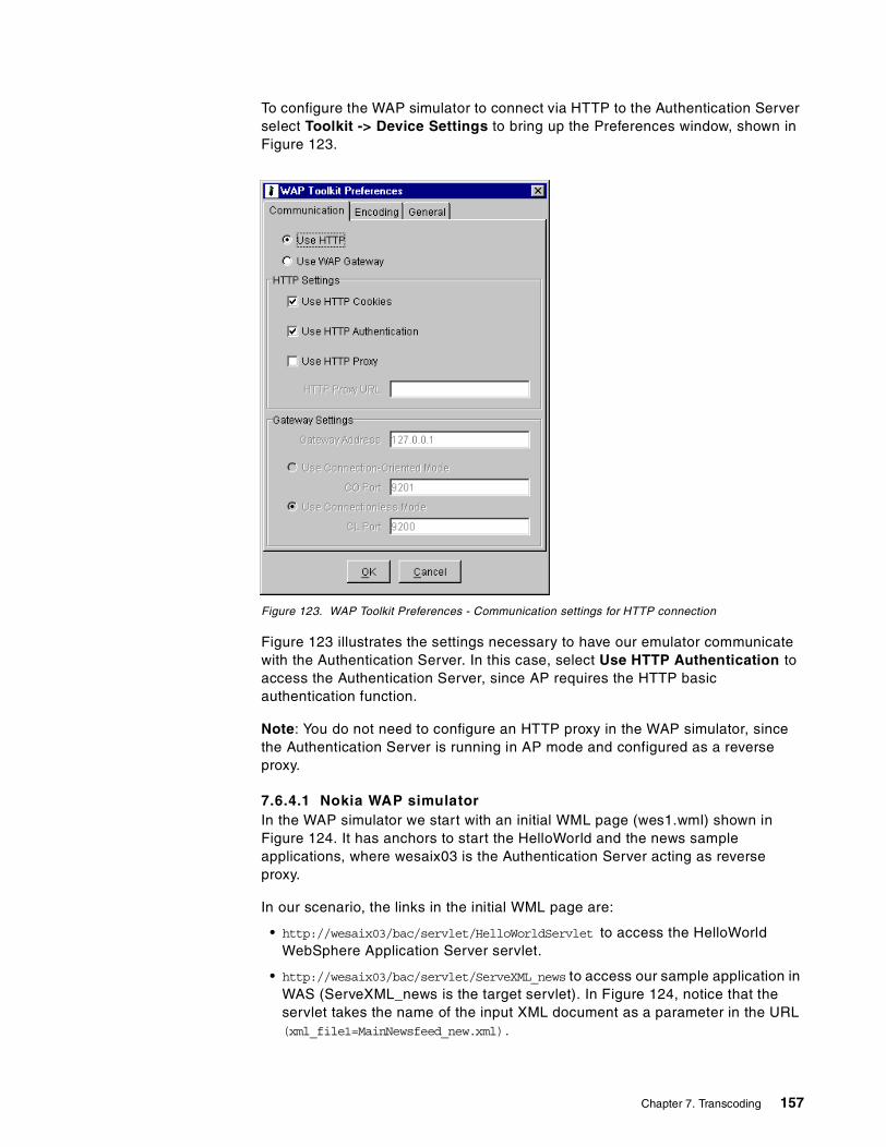
To configure the WAP simulator to connect via HTTP to the Authentication Server select Toolkit -> Device Settings to bring up the Preferences window, shown in Figure 123.
Figure 123. WAP Toolkit Preferences - Communication settings for HTTP connection
Figure 123 illustrates the settings necessary to have our emulator communicate with the Authentication Server. In this case, select Use HTTP Authentication to access the Authentication Server, since AP requires the HTTP basic authentication function.
Note: You do not need to configure an HTTP proxy in the WAP simulator, since the Authentication Server is running in AP mode and configured as a reverse proxy.
7.6.4.1 Nokia WAP simulatorIn the WAP simulator we start with an initial WML page (wes1.wml) shown in Figure 124. It has anchors to start the HelloWorld and the news sample applications, where wesaix03 is the Authentication Server acting as reverse proxy.
In our scenario, the links in the initial WML page are:
• http://wesaix03/bac/servlet/HelloWorldServlet to access the HelloWorld WebSphere Application Server servlet.
• http://wesaix03/bac/servlet/ServeXML_news to access our sample application in WAS (ServeXML_news is the target servlet). In Figure 124, notice that the servlet takes the name of the input XML document as a parameter in the URL (xml_file1=MainNewsfeed_new.xml).
Chapter 7. Transcoding 157

Figure 124. Initial WML for our sample scenario
Note: Since the connection is via HTTP to the Authentication Server, you will be prompted to enter a user ID and password as part of the HTTP basic authentication process. See also 9.9, “A sample WAP scenario” on page 202.
Figure 125. Running sample applications from WAP simulator
158 Extending e-business to Pervasive Computing Devices Using IBM WebSphere Everyplace Suite V1.1.2

By following the Everyplace News link, we get the small version of our application. The style sheet breaks down the XML page into a deck of categories and headlines. The first card shows our available categories. Each link takes us to another card that lists headlines.
Use the WML Deck (see Figure 126) in the WAP simulator to display the category card. By breaking the application down into a deck, the WAP device does not need to make a new request for the corresponding headlines and we only need one XML document for both the small-screen and large-screen versions of categories and headlines.
Figure 126. Transcoded WML for deck of categories and headlines
Chapter 7. Transcoding 159

160 Extending e-business to Pervasive Computing Devices Using IBM WebSphere Everyplace Suite V1.1.2

Chapter 8. Caching transcoded pages
Some networks use a caching proxy or cache server to store Web pages and other data so that if the same pages are requested frequently, they can be served from the cache rather than repeatedly retrieved from external Web servers. In this chapter we document how you implement IBM WebSphere Transcoding Publisher (WTP) to work with a caching proxy such as WebSphere Traffic Express (WTE) to cache transcoded pages.
8.1 Overview
If your network uses a cache server, and you want Transcoding Publisher to use it to store transcoded versions of documents, you must configure Transcoding Publisher (WTP) to use the cache server. Figure 127 illustrates a sample configuration where WTP is configured to use a caching proxy such as the IBM WebSphere Traffic Express (WTE) provided in the WebSphere Everyplace Suite.
Figure 127. Caching proxy - sample scenario
Note: In our scenario, the external cache is an HTTP proxy provided by IBM Web Traffic Express (WTE) in WebSphere Everyplace Suite (WES). However, other caching proxies such as Squid, the open source cache, Microsoft Proxy, Netscape Proxy, and Wingate can also be used.
Also, you should be aware that WebSphere Transcoding Publisher has been successfully tested with WTE and Squid. Although not formally tested, it should also function with any other product compliant with the HTTP specification.
8.1.1 Relationship to external cacheHTTP responses from Web servers may contain an explicit expiration that the external cache will obey (the HTTP header is “Expires:” followed by an HTTP-compliant date). If this header is not provided, most servers will provide a last-modified header for the resource (this header is “Last-Modified:” followed by an HTTP-compliant date). The external cache will use the last-modified date and may cache the document for a period of time. Caching of documents without the
© Copyright IBM Corp. 2001 161
expiration header is implementation specific (WTE may calculate the expiration based on the last-modified header using a different process from Squid). Most external caches that support caching based on last-modified headers will periodically verify the cached copy using "get if-modified-since" requests.
A server may also flag a resource as non-cacheable by adding either a “Pragma: No-cache” or “Cache-control: No-cache” header. It is also possible for a client to explicitly request a fresh copy (a full reload) using the “Pragma: No-cache” header on its request. This happens, for example, when you click the Reload button.
Caching transcoded results or variants is accomplished by splitting the WTP transcoding operation into two stages handled by the client and the transcoding subsystem:
1. Preference aggregation is the request is qualified with information that determines the particular variant or transcoded result.
2. Transcoding of resources based on aggregated preferences.
Preference aggregation is the process where the client's device, network type, and any other information that might cause the transcoders to produce a different variant (or permutation) of the resource are determined.
Transcoding is the process where the MEGs related to modifying the request, generating the original resource, and all of the document (or resource) editing (or transcoding) occurs.
8.1.2 Understanding cachingWhen you use a cache server with Transcoding Publisher, Transcoding Publisher stores transcoded pages in the cache. Whenever a request is received, Transcoding Publisher asks the cache for the specific document. Then, the cache component makes the decision to either return the cached document to the user or to ask the WTP transcoding subsystem for a new copy of the document. In the latter case, Transcoding Publisher will retrieve it, transcode it, and store it in the cache before returning it to the user.
The HTTP 1.1 protocol enables Web sites to specify that a page cannot be cached. For example, some main site pages, secure and session-based pages cannot be cached. If the original document cannot be cached, transcoded versions of it cannot be cached either.
The flow of data follows these steps (see Figure 128 on page 163) to retrieve a page that has not been cached:
1. Transcoding Publisher receives a request from a client to access a Web application.
2. Transcoding Publisher determines the device and network and accesses the appropriate preference profiles.
3. Transcoding Publisher resolves any preference conflicts.
4. Transcoding Publisher requests a suitably transcoded version of the application page from the cache.
5. The cache doesn't have a copy of the application page, so it asks the transcoding sublayer of Transcoding Publisher for it.
162 Extending e-business to Pervasive Computing Devices Using IBM WebSphere Everyplace Suite V1.1.2

6. Transcoding Publisher sees a new request for the transcoded version of the application page, and so it sends the request to the application server.
7. The application server processes the request and responds with the output content (HTML or XML).
8. Transcoding Publisher runs the appropriate transcoders for this document and the specific client device. If the application content is XML, a style sheet must be selected using the configured selection criteria.
9. Transcoding Publisher sends the transcoded document to the cache, in response to the request in step 5.
10.The cache keeps a copy of the resource (according to HTTP caching rules on expiration, permission to cache, etc.) and sends the transcoded version back to answer Transcoding Publisher's original request in step 4.
11.Transcoding Publisher returns the transcoded resource to the client.
Figure 128. Understanding caching steps - first request
The next time a user requests the same page, transcoded in the same way, the flow will be much simpler:
1. Transcoding Publisher receives a request from a client.
2. Transcoding Publisher requests a transcoded version of the application page from the cache.
3. The cache returns the transcoded version of the application page it has stored.
4. Transcoding Publisher returns the transcoded page to the user.
When Transcoding Publisher requests a transcoded document from the cache, all these conditions must be true:
• The requested URL must match.
• The device type in the new request, as determined from the user agent field, must match the device in the original request.
• The network type in the new request, as determined from the port on which the request was received, must match the network type in the original request.
Chapter 8. Caching transcoded pages 163

If you are not using network preferences, and all requests are being received on the default port, then this condition is satisfied.
• The cached transcoded resource has not expired, either through an explicit expiration on the resource from the original server, or because the cache has been configured to expire documents of a certain age. For documents with no expiration time specified, the cache will tell Transcoding Publisher to check the original server to see whether the document has been modified.
• The cached transcoded resource has not been removed from the cache because the cache is reaching capacity.
• The request from the device must not be for a refreshed copy of the document. The cache will not return transcoded output if the browser specifies a forced reload.
If all these conditions are met, the cache will return the requested resource and Transcoding Publisher will send it to the user.
8.2 Configuration
When you run Transcoding Publisher as a network proxy with caching, you must specify the other network servers with which it will need to interact. In some cases it may include a firewall server and a cache server.
In the Server Setup wizard, shown in Figure 129, you have to select the option to use a caching proxy.
Figure 129. Server setup - proxy configuration
Click Yes, and then you have to specify the address and listening port of the cache server (see Figure 130). You can specify the address in dotted decimal format or as a host name. If you enter a host name, Transcoding Publisher will
164 Extending e-business to Pervasive Computing Devices Using IBM WebSphere Everyplace Suite V1.1.2

attempt to validate the host name through your Domain Name System (DNS). This may cause a slight delay in processing the address.
Figure 130. Server setup - sample cache server configuration
This is the minimum configuration required for Transcoding Publisher to work with a cache server. To specify more settings, open the Administration Console and click File -> Settings -> Cache. The window shown in Figure 131 will display.
Figure 131. Administration Console - cache settings
Chapter 8. Caching transcoded pages 165
Through the Administration Console it is also possible to set the port that WTP will reserve to receive requests from the cache (the default is 9010).
The group order box in the window illustrated in Figure 131 shows the cache entrance order of MEG groups. The transcoding of a resource can also be split into several steps with intermediate caching points. This is accomplished by grouping MEGs. In this release, all default transcoders were placed in one group for this release so there is no intermediate caching by default.
Note: If you are interested in MEG groups, the WTP toolkit provides a sample scenario about how to use MEG groups and intermediate caching.
8.2.1 Considerations for configuring the external cacheWhen the external cache option is used, the external cache must be configured to allow caching of documents in the domain where Transcoding Publisher is running. This means that if Transcoding Publisher is running on machine transcode.ibm.com, the cache server must be configured to allow caching in the *.ibm.com domain.
If the external cache resides on the same machine as Transcoding Publisher (that is, if the cache and Transcoding Publisher are both installed on transcode.ibm.com), then the cache must be configured to allow caching of *.ibm.com, transcode.ibm.com, the local host, and 127.0.0.1 (the reserved IP address that represents the local machine).
If your cache uses exclusion to determine whether a document can be cached, remove any exclusions for the local host and the local domain. Depending on the cache, it may be necessary to specifically include the local host.
The following considerations apply:
1. Network settings
• WTP must be able to make a network connection to the cache (try pinging the cache from the WTP machine).
• The cache must allow caching of data from the domain and the fully resolved host name for the WTP machine.
2. Cache storage size
• If supporting only one device, the size recommended by the cache manufacturer should be sufficient.
• If supporting multiple devices/networks that are accessing the same pages through WTP, there will be a variant of the resource for every device/network combination. The recommended cache size should be increased accordingly.
8.2.2 When is caching beneficial?There are several situations where caching could be useful in a specific scenario. For example:
• WTP is being used as a portal to a limited number of Web sites/pages.
• There are multiple users using WTP as a proxy with the same device.
• The proxy will be transcoding large documents or images.
166 Extending e-business to Pervasive Computing Devices Using IBM WebSphere Everyplace Suite V1.1.2

• The browsers and devices do not have client-side caching.
In general, for caching to be useful, the pages that are retrieved do not need to be completely limited to a set of sites, but should be concentrated on a few sites. For example:
• When the same sites/pages are rarely hit, caching may not be so useful.
• When the same sites/pages are always hit, that is restricted to certain sites such as a small intranet, caching is very useful.
• When the same sites/pages are often hit, that is access is allowed to the entire Web but traffic is concentrated on the company intranet, caching still very useful.
8.2.3 Web Traffic Express (WTE) configurationThe redbook IBM WebSphere Performance Pack: Caching and Filtering with IBM Web Traffic Express , SG24- 5859 describes in detail the installation and configuration of WTE. There are two main settings that you have to configure in WTE:
• Enable cache
• Configure the directory and name file for caching
To change these settings, open the WTE Administration and Configuration utility.
8.2.4 Tuning cache serverMost HTTP caching proxies use a calculation based on the last-modified date to determine the expiration of a cached document. Many caching proxies provide a means to control this. This means that an administrator can control how long the document stays in the external cache. If your users will view a lot of pages that do not change frequently, you might save processing time by increasing the length of time a document can reside in the cache before expiring.
8.3 Troubleshooting
Since most browsers do not provide access to the response headers, there is no easy client-side method of determining the source of the transcoded output (cached resource versus new transcoded resource). However, checking the logs of the cache should provide useful information about hits and misses for transcoded resources.
If cache logs are not available or convenient, stop the IBM WebSphere Transcoding Publisher service and start the Request Viewer tool. It should list the cache plug-ins and sublayers (double-click the folder to expand the tree, as shown in Figure 132).
Chapter 8. Caching transcoded pages 167

Figure 132. Request Viewer plug-ins - caching
Select the Request Processing tab to view the requests, try to access some sites and pages to generate traffic. The window you will see should be similar to the one shown in Figure 133.
Figure 133. Requests from the client and the external cache server
168 Extending e-business to Pervasive Computing Devices Using IBM WebSphere Everyplace Suite V1.1.2

Figure 133 illustrates that for each request from the client, beginning with “http://” as in number 554, there is a request from the cache server to WTP in order to get and transcode the page for that specific request (device/network preferences), beginning with /DefaultMegGroup/ as in number 555.
The next time this page is requested from the browser, WTP will get the page already transcoded from the external cache server and will send it to the client. It is illustrated in the server request number 565 in Figure 134.
Figure 134. Requests from the client only
Most cache servers, including WTE, will add an age field in the header that indicates the document was returned from a cache.
In other words, a request from a client for a new resource will create two entries in the Request list, one for the client request, and a second for the transcoded output request. In this case, there is also an intermediate caching point, so two subsequent transcoding requests are visible.
A request from a client for cached output will create only one entry in the request list. No subsequent request appears for the transcoded resource.
There are several conditions on obtaining a cache hit:
1. Your subsequent request is not a page reload; if you are trying to verify functionality of a cache, you cannot use the Reload button in a browser, since this appends a directive to the request (in the form of an HTTP Request Header “Pragma: No-Cache”), which forces the request to be serviced by the original Web server.
Chapter 8. Caching transcoded pages 169

To verify caching, it is easier to close and open the browser again (all windows) and point to the same URL. You can also use two machines with the same browser (both IE or Netscape) and send the request for a cacheable page from the first machine, then issue the same request from the second machine.
2. The page you are looking at must be cacheable. Certain Web sites label pages uncacheable with an explicit header of “Pragma: No-Cache” or “Cache-control: No-Cache”. A page can also be uncacheable if it has expiration information (as in the case with many dynamic pages, which is very common with main pages for portals such as Yahoo or the main page of large sites) then the cache considers the content as dynamic (produced at request time) and does not cache it.
3. Make sure that your caching proxy server can cache files for the local domain.
Other not-so-common problems with corrective actions are as follows:
• Local host name not fully resolved:
• Try pinging the fully qualified host name of each one of the machines, including the browser and the external cache server. You may need to configure the Windows NT network settings and include the domain name or check the DNS configuration.
• You can also add an entry for a specific machine to the Hosts file in the /etc directory.
• In the case of multiple host name machines, ignore the warning, but cache should be in the same domain.
• The cache server must be within the same firewall as the WTP server.
• Some cache servers will never cache local files, so WTP and the cache server may need to be on two different machines.
• The URL in the cache log should contain the name of the MEG groups for all of the enabled MEGs, preference values that are used to determine the variants and the original URL.
For example:
http://M238P4XL.itso.ral.ibm.com:9010/DefaultMegGroup%2Fdevice_SOURCE%3DNT.Netscape45%2Fuser_SOURCE%3Duser_default%2Fnetwork_SOURCE%3Ddefault%2FlocalPort%3D8088%2FUA_pixels%3Dnull%2FUA_color%3Dnull%24%57%42%49%24http:www.pc.ibm.com/us/index.html
170 Extending e-business to Pervasive Computing Devices Using IBM WebSphere Everyplace Suite V1.1.2

Chapter 9. Wireless Gateway
The IBM Everyplace Wireless Gateway is an open-system communication platform that enables IP applications to run in wireless environments. It provides support for wireless clients using the optimized Wireless Link Protocol (WLP) and WAP devices. In addition, it also supports dial-in (PPP) and LAN connections. This chapter helps you to set up and configure the Wireless Gateway and illustrates some of its most important included functionality.
9.1 Introduction
The Wireless Gateway extends the corporate network for e-business solutions and protects existing investment in software and information technology infrastructures. It enables secure, optimized access by mobile client devices such as notebook with wireless modems, personal digital assistants (PDAs), and many WAP-enabled smart phones and communicators over a wide range of wireless networks as well as wireline networks such as local area networks (LANs) and wide area networks (WANs).
In this chapter we first go through some basic configurations after a standard installation of the Everyplace Wireless Gateway. Secondly, we will specifically show how to configure the Everyplace Wireless Gateway into a WAP gateway. Thirdly, we will go through our sample applications using the WAP gateway and the rest components of the Everyplace Suite. Everyplace Wireless Gateway is a scalable platform and can be configured into a cluster to host tens of thousands of concurrent users. We will give a brief account on how to configure a cluster of wireless gateways. Finally, we will discuss several security scenarios that are supported in this release. The gateway administration after the installation and configuration will be conducted through the administration tool called Gatekeeper, which is covered in Chapter 10, “Wireless Gateway administration” on page 207.
The Everyplace Wireless Gateway was previously known as SecureWay Wireless Gateway. For those who are familiar with the SecureWay Wireless Gateway, the redbook entitled Mobile Computing: The eNetwork Wireless Solution, SG24-5299 covers many details of wireless gateways. For those who are interested in the architecture of the Everyplace Wireless Gateway, the redbook entitled An Introduction to IBM WebSphere Everyplace Suite Version 1.1, SG24-5995 explains the design of the Wireless Gateway and its role in the WebSphere Everyplace Suite product.
9.2 Overview
With increasing numbers of business activities being conducted outside traditional office buildings, tools and services that allow mobile professionals to access and interact with information (and services) relevant to their enterprises are in great demand. In the meantime, Internet transactions are becoming increasingly mobile as well. It is forecasted that in the next few years, about two-thirds of all Internet transactions are expected to be generated by new wireless and mobile devices. In the emerging mobile business climate, wireless and mobile devices must work together seamlessly with both the Internet and enterprise intranet. Moreover, given the sensitive nature of business information, transactions must be conducted with the highest levels of security.
© Copyright IBM Corp. 2001 171

As one of the core components of the IBM WebSphere Everyplace Suite, the IBM Everyplace Wireless Gateway adds connectivity, security, and optimization to the Suite. The Everyplace Wireless Gateway supports numerous world-wide network technologies including the Wireless Application Protocol (WAP). It provides the core WES functions by tightly integrating with many other components within the Suite.
The Everyplace Wireless Gateway provides connections over a wide range of wireless, dial-in, and wireline networks and does so by shielding any network-specific operations from the user application. Over wireless and wireline networks, Web and enterprise application programs using a standard TCP/IP interface can be accessed via the Wireless Gateway. In particular, using an array of innovative implementations, the Wireless Gateway facilitates the lightweight, low-processing power, and low-bandwidth WAP clients to access the Web. The Wireless Gateway also provides wireless network-specific enhancements to TCP/IP communications. Such enhancements as data compression, encryption, authentication, optimization, and retransmission are particularly beneficial to the wireless clients due to the limited bandwidth, high latency, low reliability, and security risks inherent in today’s wireless networking technologies.
9.2.1 Supported featuresAs shown in Figure 135, Everyplace Wireless Gateway Version 1.1 includes the following features:
• Support for the WAP Version 1.2
• Short Message Services (SMS) information push proxy
• Standard support for Internet Protocol (IP) applications over both IP and non-IP wireless bearer networks
• Distributed and scalable gateway design using dynamic clustering technology to balance load and improve availability
• Allow multiple gateways to access end-user and network configuration information from a central, highly scalable LDAP-based directory
Figure 135. IBM Everyplace Wireless Gateway provides connectivity
Everyplace Wireless Gateway
Secure Application
Servers
Intranet/Internet
Dial-up
WAP / Wireless
WirelessGatewayClients
Mobile
Netw
orkC
onnections
172 Extending e-business to Pervasive Computing Devices Using IBM WebSphere Everyplace Suite V1.1.2

The Wireless Gateway provides a communications platform that enables Internet Protocol applications to run in wireless environments. The Wireless Gateway provides mobile devices containing wireless clients with wireless access to host and network resources through radio and dial-in networks. The Wireless Gateway encrypts, compresses, and minimizes the data that passes through the wireless link, thereby increasing the speed of messaging.
IBM Everyplace Wireless Gateway provides connectivity the IBM WebSphere Everyplace Suite domain, jointly with the IBM Everyplace Authentication Server (EAS). It provides non-WAP wireless, WAP wireless, and other wireline connections such as dial-in connections to and from the IBM WebSphere Everyplace Suite. It establishes the communication connection to and from pervasive devices and translates those connections to IP and other standard protocols.
For non-WAP wireless clients, the Everyplace Wireless Gateway includes wireless client application software that extends TCP/IP communications to mobile devices running over a variety of network connections. Like its predecessor, the IBM SecureWay Wireless Gateway, the Everyplace Wireless Gateway is designed to enable TCP/IP applications to run without modification efficiently, securely, and reliably over packet-radio networks that do not support TCP/IP.
With the increasing popularity of mobile access to the Internet using WAP-enabled phones, supporting WAP devices has become the natural progression of the Wireless Gateway. For WAP-enabled mobile devices, the Everyplace Wireless Gateway supports WAP 1.2. The Wireless Gateway server accepts WAP requests over numerous network connections to preserve the operation of existing Web applications. The gateway server converts the request in WAP to an HTTP request and forwards that request to the existing Web infrastructure, and in turn translates the HTTP response from the existing Web applications to a WAP response and sends this response to the WAP device.
The Everyplace Wireless Gateway also supports dial-in connections to the WebSphere Everyplace Suite. Such dial-in connections can be from a wireline network or a wireless network using supported wireless modems. The Wireless Gateway utilizes the Point-to-Point Protocol to authenticate the dial-in clients and provides secured tunneling to the TCP/IP applications hosted by the WES domain. However, in order for the clients to access the Everyplace Wireless Gateway, the Everyplace Wireless Client software application must be installed on the client devices (except for PPP connections).
The Everyplace Wireless Gateway server and client application software work together to establish secure wireless and wireline communications between devices and the Wireless Gateway by providing two-way authentication, and data encryption for confidentiality.
The IBM Everyplace Wireless Gateway connects pervasive devices to IP networks. When possible, it also maintains a VPN link between the pervasive devices and the WES services. Links to WES through the Wireless Gateway are considered to be trusted by the WebSphere Everyplace Suite domain, because the Wireless Gateway terminates and authenticates the data link layer of the network stack.
Chapter 9. Wireless Gateway 173

The Everyplace Wireless Gateway authenticates:
• Dial-in connections from devices using the Point-to-Point Protocol (PPP) to make the connection.
• Wireless connections from devices that support WAP.
• Secure connection from devices using the Everyplace Wireless Client to make the connections.
For devices that use wireless clients, customers must install the client software on the devices.
For the Everyplace Wireless Gateway client-to-server connections, the Wireless Gateway supports the Data Encryption Standard (DES), RC5, and 3-DES encryption world-wide. This results in a secure tunnel between client and server using the WLP protocol.
For WAP connections, the Everyplace Wireless Gateway utilizes the Wireless Transport Layer Security (WTLS) to perform gateway authentication and data encryption. WTLS is a WAP security implementation similar to the traditional Transport Layer Security (TLS) over TCP/IP networks. However, WTLS does not interoperate with TLS. More details about the Wireless Gateway security are provided in 9.8, “Gateway security scenarios” on page 198.
An additional security measure prevents unwanted packet data from being transmitted. The Everyplace Wireless Gateway provides packet filtering for wireless clients and PPP connections as well as a mapping mechanism to filter out unsolicited or unwanted data. This not only reduces the chance of malicious attacks but also reduces the traffic on the wireless link.
9.2.2 Optimization techniquesThe Everyplace Wireless Gateway server and client application software work together to optimize the wireless communications between devices and the server. The client and server software compresses data to reduce unnecessary protocol headers and optimizes TCP communication to increase the effective data rate and lower the network cost.
The first optimization technique provided by the Everyplace Wireless Gateway is compression. Prior to the transmission of the IP packets, the size of each IP packet is reduced without any impact on the content of the packet. This compression increases the effective data rate of the wireless network and it also decreases the amount of data transmitted and therefore decreases the transmission cost in most cases.
The second optimization technique provided by the Everyplace Wireless Gateway also works for TCP traffic only. It is called TCP header reduction. This technique reduces the 40-byte TCP headers to an average size of 3-5 bytes, which decreases the amount of data to be transmitted over the wireless network.
The third technique is called TCP retransmission optimization. It’s been observed that TCP communication over wireless links often results in packet retransmission
Packet filtering is not available for WAP connections.
Note
174 Extending e-business to Pervasive Computing Devices Using IBM WebSphere Everyplace Suite V1.1.2

because of the high latency and small bandwidth available. The IBM Everyplace Wireless Gateway provides unique solutions to address such problems.
Finally there is a technique that reduces the air time on connection-oriented wireless network and PSTN. This technique is called short hold mode. With short hold mode enabled, there can be no established physical connection over the mobile network, but the client and server are virtually connected. If the client or gateway asks to transmit an IP packet, the client or gateway will re-establish the connection and start the transmission immediately. As a result, this technique may lower connection fees.
9.3 Deployment of the Everyplace Wireless Gateway
The IBM WebSphere Everyplace Suite is targeted to network operators, content providers, service providers such as ISP and ASP, and enterprises. Different customers may deploy the Everyplace Wireless Gateway differently based on their functionality needs. However, a general set of considerations exist for the deployment of the Everyplace Wireless Gateway. Such considerations should cover the areas of performance, scalability, availability, and security.
The Everyplace Wireless Gateway can be installed on a single server along with other products, or it can be installed separately on a dedicated server in a distributed format. IBM recommends that the distributed form be used, separating security services, content adaptation, management services, base services, and connection services.
In order to achieve high performance in providing WAP and wireless services to clients, it is recommended that you use the Everyplace Wireless Gateway in conjunction with the Edge Server - Caching Proxy. The WTE HTTP proxy can enable both Web and WAP content caching for faster services.
Better performance and high availability can also be achieved by using the Everyplace Wireless Gateway cluster support. Having multiple Wireless Gateways in one cluster can improve the service response time and minimize the service downtime.
Similarly the IBM Network Dispatcher can be used to support multiple HTTP proxy servers behind Wireless Gateways. However, the IBM Network Dispatcher is not recommended to be used in front of the Wireless Gateways.This is because the Network Dispatcher is based on TCP/IP while the Wireless Gateway supports many non-IP networks, such as WAP bearer networks. When there are non-IP connections, the Network Dispatcher’s load-balancing feature is no longer applicable. In addition, WAP connection-oriented sessions and WTLS secure transactions may not be efficiently dispatched by the Network Dispatcher. Moreover, for WAP gateways that do not share WAP persistent data among multiple gateways or WAP stacks, there would be further restrictions for using the
In a distributed environment, customers can install most of the WebSphere Everyplace Suite components on their own physical machines to provide scalability, higher reliability, and performance. Single-function machines can be tuned more easily with fewer interruptions due to cross-product problems.
Note
Chapter 9. Wireless Gateway 175

Network Dispatcher. The WAP session suspend-and-resume function is not reliably supported because the client will likely resume with a different IP address.
For scalability considerations, and the considerations for the provision of virtual private networks (VPNs) as well as the considerations for interfacing with existing corporate or subscriber access control, it is recommended that the Everyplace Wireless Gateway be configured to use external authentication processes such as the Remote Authentication Dial-In User Service (RADIUS) server, even though it has a self-contained authentication method for stand-alone use.
For security considerations, the connection between the Wireless Gateway and the Wireless Gatekeeper must be SSL-enabled. Furthermore, the connections among multiple gateways in a cluster environment should be SSL-enabled as well.
In An Introduction to IBM WebSphere Everyplace Suite Version 1.1, SG24-5995, we have presented six cases of deployment of the Everyplace Wireless Gateway for the network operators, content providers, and service providers. Here we list three examples for how the Wireless Gateway works with other components in WebSphere Everyplace Suite to provide solutions to a package-delivery enterprise, a service provider, and a content provider.
9.3.1 Delivery enterpriseFigure 136 shows how Everyplace Wireless Gateway is used in conjunction with two other components in the Everyplace Suite, namely the MQSeries Everyplace and Everyplace Synchronization Manager, to provide a solution for a package-delivery enterprise.
Figure 136. Wireless Gateway deployed for a package-delivery enterprise
The package delivery professionals are equipped with appropriate wireless hand-held devices that scan the barcodes of the packages, capture customer signatures, and update the delivery status. Currently, a package-delivery company uses hand-held computers to temporarily scan, capture and store delivery data. The data is not synchronized with the central database until the delivery professionals return to the base and hook the hand-held computers to a workstation that is connected to the central database servers.
With Everyplace Wireless Gateway, the delivery professionals are able to update the delivery information instantaneously. All communications are enabled through
176 Extending e-business to Pervasive Computing Devices Using IBM WebSphere Everyplace Suite V1.1.2

Everyplace Wireless Gateway, which authenticates and maintains the wireless connection between the hand-held devices in the field and the central enterprise information technology infrastructure.
With the help of the Everyplace Synchronization Manager, the wireless hand-held computers can synchronize with the central databases continuously over the wireless network. MQSeries Everyplace enables secure and reliable transactional updates of the delivery information. Such a solution could greatly improve the availability of the delivery information to the customers and increase the customer satisfaction.
9.3.2 Internet Service Provider (ISP)Figure 137 shows how a typical Internet Service Provider (ISP) can utilize Everyplace Wireless Gateway to enable mobile Internet access for its subscribers. A typical solution employs multiple components in the IBM WebSphere Everyplace Suite.
Figure 137. Wireless Gateway deployed for an Internet Service Provider
The Wireless Gateway provides the connection gateway for the mobile devices. The subscriber authentication is done by both Everyplace Authentication Server and Everyplace Wireless Gateway, utilizing the RADIUS database included in the Tivoli Personalized Service Manager (TPSM). TPSM also maintains the user and device profiles for the subscribers. WebSphere Transcoding Publisher is needed to convert the traditional TCP/IP contents to formats suitable for a variety of mobile devices. In addition, the IBM Edge Server is used to provide scalability for large subscriber bases.
9.3.3 Content providerFigure 138 shows how a content provider can use Everyplace Wireless Gateway to provide content to its mobile subscribers. The content provider can be a bank providing financial information for its customers, an airline providing ticket, arrival, and departure information for its passengers, or an Internet portal providing categorized information to its browsers. Again, the Wireless Gateway is needed for the communication channels between the mobile subscriber and the content.
Chapter 9. Wireless Gateway 177

Figure 138. Wireless Gateway deployed for a content provider
In addition to those components providing authentication (Everyplace Authentication Server, TPSM), user/device profiles (TPSM), content adaptation (WebSphere Transcoding Publisher), transaction management (MQSeries), and load balancing (Edge Server), a content provider can also use Edge Server as the content caching proxy for faster delivery of the data to its subscribers.
9.4 Install Everyplace Wireless Gateway
Installation of Everyplace Wireless Gateway can be an easy task with good preparation beforehand. Several resources for installation are included in the Everyplace Suite. The installation engineer is encouraged to read the Everyplace Wireless Administrator’s Guide to understand how the Wireless Gateway works in a WebSphere Everyplace Suite environment or in a custom stand-alone environment.
The WebSphere Everyplace Suite Getting Started manual also provides some hints on post-configuration steps to enable the Wireless Gateway to access the RADIUS database and the Active Session Table (AST).
Several configuration considerations are recommended:
• The installation engineer should run through the installation process at least once before installing the production system.
• It is very helpful if the installation engineer draws a diagram of the environment that depicts the following:
• All WebSphere Everyplace Suite components needed for the solution
• All Everyplace Wireless Gateway components needed for the solution
• All routers, firewalls and IP subnets
• All servers including database servers, Web servers, etc.
• The installation engineer should pilot the solution using the minimal production configuration with all of the components
178 Extending e-business to Pervasive Computing Devices Using IBM WebSphere Everyplace Suite V1.1.2

Additionally, the following steps are recommended for the Wireless Gateway environment:
1. Run the LDAP directory services on a separate system
• LDAP backup may be handled by Wireless Gateway using the "mirror" feature.
• Remember to run LDIF to synchronize files.
2. Run the DB2 database on a separate system. It may be run on the same system as Wireless Gateway for smaller systems.
3. Run Edge Server - Caching Proxy on a separate system from Mobile Network Connection for increased security.
4. Use Wireless Gateway cluster nodes for load balancing and increased capacity.
5. Run Edge Server Network Dispatcher behind Wireless Gateway (not in front).
6. Run Mobile Network Connection on systems in an HACMP environment for high availability.
7. Run Wireless Gatekeeper on a separate system from Wireless Gateway. The Gatekeeper can run in AIX, Linux, Solaris, and Windows environments.
Before starting the installation:
1. Make sure all prerequisite software is installed:
• LDAP Client
• DB2 Client
2. Make sure you have the latest updates.
3. Make sure there is enough space in file systems.
The WebSphere Everyplace Suite Getting Started manual includes a chapter on installation that provides a checklist for installation, the requirement for the correct PTF levels of the AIX operating system, and guidelines for the file space. The installation engineer is expected to follow those guidelines during the installation.
To minimize the chance of failure, the following precautions might be useful to the installation engineer:
1. Take the default values and get the Wireless Gateway up and running.
2. Start and test the Wireless Gateway in a LAN environment using the WAP simulator and wireless LAN clients.
3. Then add additional features and functions.
The minimal environment for Everyplace Wireless Gateway to run is:
• LDAP for configuration and user profiles.
• DB2 for persistent data storage.
• WTE for WAP caching.
Note
Chapter 9. Wireless Gateway 179

As we explained before, Everyplace Wireless Gateway can be installed in an integrated process in conjunction with the installation of the WebSphere Everyplace Suite. However, since it acts as one of the two entry points of the Everyplace Suite, customer deployment often requires separate installation of the Everyplace Wireless Gateway in a stand-alone environment. This kind of installation is done with the smitty tool in the AIX operating system.
While the integrated installation of the Wireless Gateway in the Everyplace Suite is briefly covered in Chapter 2, “Installation guidelines” on page 29, Figure 139 through Figure 143 illustrate a stand-alone installation for the Wireless Gateway.
Figure 139. Installation of the Everyplace Wireless Gateway using smitty
The smitty tool is used to install a stand-alone Wireless Gateway. The command is invoked from an AIX prompt. Choose Software Installation and Maintenance, which brings up a window allowing you to choose how to install the software, as shown in Figure 140.
Figure 140. smitty Wireless Gateway installation: select install
180 Extending e-business to Pervasive Computing Devices Using IBM WebSphere Everyplace Suite V1.1.2

For a fresh stand-alone installation of the Wireless Gateway, choose Install and Update from LATEST Available Software. Then you will be prompted to enter the destination path of the software. A typical path is given in Figure 141.
Figure 141. smitty Wireless Gateway installation: input path
In the Software to Install field, we choose _all_latest ( see Figure 142).
Figure 142. smitty Wireless Gateway installation: software install
Leaving the rest of the fields with their respective default values, press Enter for the installation. As shown in Figure 143, you will be prompted to confirm your choices. Press Enter again to start the installation.
Chapter 9. Wireless Gateway 181

Figure 143. smitty Wireless Gateway installation: verify
The software should be installed subsequently. After the installation, the software is merely transferred to the hard disk of the server. To bring the Wireless Gateway up, some basic configuration needs to be done.
9.5 Basic configuration
IBM Everyplace Wireless Gateway and Gatekeeper are installed by the WebSphere Everyplace Suite installer in the coordinated installation. However, the Everyplace Wireless Gateway has not been enabled yet. The configuration of the Everyplace Wireless Gateway has to be completed using the Gatekeeper after the installation. Moreover, the Everyplace Wireless Gateway can run in a minimal environment without the installation of the IBM WebSphere Everyplace Suite as illustrated in 9.4, “Install Everyplace Wireless Gateway” on page 178. This section will walk through the configuration of the Everyplace Wireless Gateway that is necessary to run Everyplace Wireless Gateway within a WES domain or within a minimal environment.
When installing Wireless Gateway for the first time, regardless of whether the Everyplace Wireless Gateway is installed in a WES domain or a minimal environment, the Wireless Gateway has to be enabled by invoking the Gatekeeper. Using the Gatekeeper to log in the gateway for the first time, the user must be defined as the “root” of the gateway. While a user can use Gatekeeper from any workstation on the network to log in remotely, the Gatekeeper can be simply invoked on the gateway machine using the wgcfg command.
The configuration of the Wireless Gateway for the first time starts with configuring the Access Manager. This requires the user to enter LDAP server access parameters to store persistent data, as shown in Figure 144.
182 Extending e-business to Pervasive Computing Devices Using IBM WebSphere Everyplace Suite V1.1.2

Figure 144. Gatekeeper Access Manager configuration: LDAP access parameter
Then the configuration will require user to identify a key database filename and s stash password file name to enable SSL traffic between the Gatekeeper and the Access Manager, as shown in Figure 145.
Figure 145. Gatekeeper Access Manager configuration: SSL databases
Go through the following steps to complete the Wireless Gateway configuration to create a new gateway:
Chapter 9. Wireless Gateway 183

1. The first part of the Wireless Gateway configuration is to specify the persistent day storage for session information, accounting and billing information, as well as the logging information. The window shown in Figure 146 shows the prompt for the session database.
Figure 146. Ask for database server and port information for session information
Similarly, Gatekeeper will prompt you for accounting and billing information. Then the Gatekeeper will ask for log file names for error, debug, and tracing information, as shown in Figure 147.
184 Extending e-business to Pervasive Computing Devices Using IBM WebSphere Everyplace Suite V1.1.2

Figure 147. Gatekeeper prompts for log file names for errors
2. The second step is the option to use the RADIUS server. As displayed in Figure 148, Gatekeeper prompts for RADIUS server information.
Figure 148. Option to use RADIUS server and prompts for server information
Notice that since Wireless Gateway has its own mechanism to authenticate users, in a minimum environment, Wireless Gateway can run without using the
Chapter 9. Wireless Gateway 185

RADIUS server. However, in the WebSphere Everyplace Suite environment, the RADIUS server is recommended. More discussion on security scenarios is given in 9.8, “Gateway security scenarios” on page 198.
Because of the complexity of the Everyplace Wireless Gateway supporting many types of bearer networks, which requires a variety of configuration parameters, incorrect and missing data can cause the configuration process to fail. Therefore, it is recommended that for a first-time configuration of the Wireless Gateway, the user should use default values to get it up and running. That is, for steps 3 to 5, the user can select not to install WAP support, MNI, and MNC during a first-time configuration. The user can go to step 6, add an administrator user ID and password, and start the Gateway to get it up and running.
3. The third step is to set up WAP support. With WAP support enabled, the Wireless Gateway can also be called a WAP gateway. The details on how to set up a WAP gateway are in 9.6, “WAP Gateway configuration” on page 190.
4. The fourth step is to add one or more Mobile Network Interfaces (MNI). MNI provides virtual trusted subnetworking for the Wireless Gateway. It is a network interface that routes IP traffic through the Wireless Gateway for wireless clients and for WAP clients that use a native PPP connection. MNI can support static addressing and the Dynamic Host Configuration Protocol (DHCP). Figure 149 and Figure 150 illustrate the MNI windows.
Figure 149. Choice to add mobile network interface
The rule of thumb for the configuration of the Wireless Gateway is:
• Take the default values and get it up and running.
• Then add additional features and functions such as WAP, MNIs, and MNCs.
Note
186 Extending e-business to Pervasive Computing Devices Using IBM WebSphere Everyplace Suite V1.1.2

Figure 150. Gatekeeper prompts information to set up the MNI
5. The fifth step is to add one or more Mobile Network Connections (MNC). MNC Figure 151 is the window prompting for an MNC connection.
Figure 151. Choice to add mobile network connection to Wireless Gateway
If the user chooses to install MNC, a drop-down list of supported MNCs is presented, as shown in Figure 152.
Figure 152. List of supported MNCs
For each specific MNC that a user chooses to install, the Gatekeeper will ask for network-specific information for that MNC. For example, to set up a serial line
Chapter 9. Wireless Gateway 187

interface TTY type MNC, the user is prompted for specific information, as shown in Figure 153.
Figure 153. Information needed to set up a serial line interface
6. The sixth step is to create administrators for future access to the Wireless Gateway from the Gatekeeper. Figure 154 shows the process to set up the administrator and the access control list.
Figure 154. Add new administrator for the Wireless Gateway
188 Extending e-business to Pervasive Computing Devices Using IBM WebSphere Everyplace Suite V1.1.2

Next, as shown in Figure 155, you will need to select the resources to which the administrator will have access.
Figure 155. Add access control list for the new administrator
For a specific resource, select the access type as illustrated in Figure 156.
Figure 156. Completing the access control for the new administrator
Enter the miscellaneous information required for the password and the account in Figure 157.
Chapter 9. Wireless Gateway 189
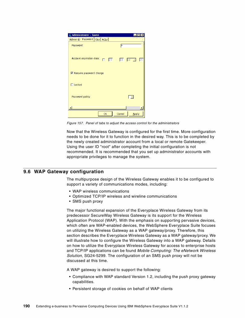
Figure 157. Panel of tabs to adjust the access control for the administrators
Now that the Wireless Gateway is configured for the first time. More configuration needs to be done for it to function in the desired way. This is to be completed by the newly created administrator account from a local or remote Gatekeeper. Using the user ID "root" after completing the initial configuration is not recommended. It is recommended that you set up administrator accounts with appropriate privileges to manage the system.
9.6 WAP Gateway configuration
The multipurpose design of the Wireless Gateway enables it to be configured to support a variety of communications modes, including:
• WAP wireless communications • Optimized TCP/IP wireless and wireline communications • SMS push proxy
The major functional expansion of the Everyplace Wireless Gateway from its predecessor SecureWay Wireless Gateway is its support for the Wireless Application Protocol (WAP). With the emphasis on supporting pervasive devices, which often are WAP-enabled devices, the WebSphere Everyplace Suite focuses on utilizing the Wireless Gateway as a WAP gateway/proxy. Therefore, this section describes the Everyplace Wireless Gateway as a WAP gateway/proxy. We will illustrate how to configure the Wireless Gateway into a WAP gateway. Details on how to utilize the Everyplace Wireless Gateway for access to enterprise hosts and TCP/IP applications can be found Mobile Computing: The eNetwork Wireless Solution, SG24-5299. The configuration of an SMS push proxy will not be discussed at this time.
A WAP gateway is desired to support the following:
• Compliance with WAP standard Version 1.2, including the push proxy gateway capabilities.
• Persistent storage of cookies on behalf of WAP clients
190 Extending e-business to Pervasive Computing Devices Using IBM WebSphere Everyplace Suite V1.1.2

• Security features based on the Wireless Transport Layer Security ( WTLS)
• Making requests to Web servers using Secure Sockets Layer (SSL) on behalf of WAP clients
• Choice of encryption algorithm and key strengths for both key exchange and bulk encryption methods
• WAP user authentication integrated with the Everyplace Authentication Server
• Certificate authentication for WAP 1.2-compliant clients
• Interfaces to IP-capable networks such as Cellular Circuit-Switched Data and IP packet-based networks, as well as SMS network types
• Network management of the WAP gateway via the Simple Network Management Protocol (SNMP)
• Accounting records are stored in an ODBC relational database, allowing external applications easy access to billing data
WAP gateway allows the lightweight, low-processing- power, low-bandwidth WAP clients to access the Web. It acts as a translator/encoder between the WAP clients that use the Wireless Session Protocol (WSP), and the Internet, which uses the HyperText Transport Protocol (HTTP). It also acts as an agent for WAP clients, such as phones and PDAs, by storing cookies and maintaining secure HTTPS connections on their behalf. In the course of providing WAP communications, the Wireless Gateway implements high-strength security and high-performance caching.
The WAP gateway converts the WSP session from the WAP client to HTTP for the Internet or intranet Web servers via the proxy. The gateway also performs the binary encoding and decoding of the content, and converts the HTTP response to WSP for delivery to the WAP clients.
The data flow for a typical WAP communication via the Everyplace Wireless Gateway is depicted in Figure 158. The process is as follows:
• Data is received from the WAP protocol stack.
• A request is validated and converted from binary WAP language to standard Web protocols. Additional HTTP request headers are added (such as cookies, WES integration headers, etc.).
• The request is forwarded to the Caching Proxy, which is a WTE with a Wireless Gateway plug-in.
• A response is received, cookies are processed, WML documents are converted to binary WML.
• HTTP headers are binary encoded.
• Response data is sent back to the WAP client.
Chapter 9. Wireless Gateway 191

Figure 158. The data flow for the WAP requests
If you choose to add WAP support (see Figure 159), the Gatekeeper will ask you to specify whether the WAP gateway will be a connection-oriented gateway or a connectionless gateway. It also asks the user to specify whether the connection between WAP clients and the gateway should be secured (see Figure 160 on page 193).
Figure 159. The choice to add WAP support
In addition, the Gatekeeper asks the user to specify the HTTP proxy server for the WAP gateway (see Figure 161).
W APSTACK
W apBrow seServiceConnection-lessNot securePort 9200
W apBrow seServiceC onnection-orientedN ot SecurePort 9201
W apBrow seServiceC onnection-lessSecurePort 9202
W apBrow seServiceC onnection-lessSecurePort 9203
HTTPReceiver
HTTPConnector
HTTP ProxyServer / W eb
Servers
Request F lowResponse F low
1
6
5
4
3
2
W APClients
192 Extending e-business to Pervasive Computing Devices Using IBM WebSphere Everyplace Suite V1.1.2

Figure 160. WAP gateway browsing services and designated ports
The user also has a choice to enable the HTTP cookie support for the WAP client (see Figure 162).
Figure 161. HTTP proxy is needed for WAP gateway
Chapter 9. Wireless Gateway 193

Figure 162. User has choice to enable HTTP cookie support
Moreover, for the WAP gateway, Gatekeeper also presents a choice for the user to add a push proxy gateway (see Figure 163). As explained earlier in this chapter, Everyplace Wireless Gateway supports push access for WAP clients. That is, it can act as a push access gateway. If the user chooses to add the push access gateway, more questions will be asked by the Gatekeeper, such as port number for the push access gateway.
Figure 163. Choice to add push access support to the Wireless Gateway
Now that we have completed the configuration for a WAP gateway, we can use a WAP simulator to test whether the WAP configuration is set correctly. One way to do this is to install a Nokia WAP simulator in a separate machine over the local LAN. The details of setting up the WAP simulator will not be discussed here, since the instruction is only relevant to what simulator the user chooses to use. However, there are a few things to remember:
1. WAP simulators are not the same as real WAP devices
2. Everyplace Wireless Gateway does not support HDML or non-WAP-standard phones
3. Make sure all WAP phones/simulators are programmed to connect to the Wireless Gateway according to their own manuals.
194 Extending e-business to Pervasive Computing Devices Using IBM WebSphere Everyplace Suite V1.1.2

Finally, in order to fine tune the WAP gateway to provide the solution for the particular business application, the user needs to tune a set of gateway parameters. Let’s illustrate a sample set of parameters for a WAP gateway operational scenario. As mentioned in the Wireless Gateway Administrator’s Guide as well as in An Introduction to IBM WebSphere Everyplace Suite Version 1.1, SG24-5995, Everyplace Wireless Gateway is capable of supporting tens of thousands of active WAP users. However, such capability is only to be achieved by configuring the Wireless Gateway in an optimized fashion. While the scaling and sizing issues of the Wireless Gateway are constantly under study, we offer here our sample set of parameters for the user to support 5,000 active users, as shown in Table 3.
Table 3. Sample configuration parameters to support 5000 active WAP users
Remember to restart the Wireless Gateway daemon after changing parameters to make the changes effective. A few notes are worth mentioning again. Port 9200 is used for connectionless operation, while port 9201 is used for connection-oriented operation. For optimum performance over a secure WAP connection, one should increase the WAP Gateway/WTLS/Key refresh frequency. One rule of thumb is always to adjust all parameters according to the number of active users.
9.7 Wireless Gateway Clustering
In order to handle high traffic networks, clustering has been incorporated into the design of the Wireless Gateway. Clustering, in the context of the Everyplace Wireless Gateway, is the grouping of several machines (each running one instance of the Gateway), as illustrated in Figure 164 on page 196. Workload from one or more network connections is distributed across them. Each node, in addition to taking advantage of UNIX multiprocessor capabilities, runs its own WAP protocol stack. Multiple clusters may exist on the same physical set of boxes.
Wireless Gateways share three major resources that make clustering possible:
1. A relational database (such as DB2 or Oracle) that contains persistent session data.
2. An LDAP directory server that contains gateway configuration and user data.
Configuration Parameter Value
Session cache size 20000
Broker/Connection table size 20000
Broker/Message queue length 50000
9200/Maximum pending connection requests
1000
9200/Maximum pending events 5000
9201/Maximum pending connection requests
7500
9201/Maximum pending events 20000
Chapter 9. Wireless Gateway 195

3. A single point of administration: the Wireless Gatekeeper. Wireless Gatekeepers are managed by the Gateway’s Access Manager (AM). An AM supports the many-to-many relationship between Gatekeepers and Gateways. The AM insures that one Gatekeeper locks administration of the Gateway topology, in effect preventing overwriting of other configuration modifications by forcing the other Gatekeepers into read-only mode. The AM communicates between the Gateway to Gatekeeper using XML messages.
Figure 164. Distributed IBM Everyplace Wireless Gateway servers
Figure 164 shows all the components of a Gateway cluster. Tivoli, the application servers, and the Web servers are all accessed through the WebSphere Everyplace Suite. The Gateway itself communicates with the Gatekeeper, a relational database, LDAP directories, and with outside networks via MNCs.
9.7.1 Cluster Manager (CM)The Cluster Manager is a function of the Wireless Gateway that allows for Gateway-to-Gateway communication in order to share workload and to balance CPU usage in a cluster.
The Cluster Manager allows nodes to be dynamically added and removed from a cluster. To introduce a node to a cluster, the Gatekeeper must be configured with the node’s IP address and port number. The Cluster Manager will then begin to distribute requests to the new node. To remove a node, delete it from the Gatekeeper. Traffic will then be distributed over the rest of the cluster.
The Wireless Gateway Cluster Manager can be configured in one of three ways:
Networks
WAP Clients
Web Servers
MNCsMNCs
MNCs
Gateway N
Gateway 2Gateway 3
MNCs
Gateway 1
AB
C
Config,& Admin.
Data
LDAPGatekeeper
JAVAAdmin GUI
Gatekeeperto GatewayAccess Mgr
[AM]
XML
WAP DataSTORE
&AccountingDatabase
RDB
TIVOLI
Subscriber,Device &NetworkManagement
RDB
UserAuthentication
RADIUS
RelationalDBMS access
ODBC
LDAP
Web ServerAccess
HTTP & HTTPS
ApplicationServers
C/S ApplicationAccess
TCP/IP
PPP andWireless Clients
196 Extending e-business to Pervasive Computing Devices Using IBM WebSphere Everyplace Suite V1.1.2
1. As a principal node:
• Receives network traffic from an MNC and distributes load to itself and subordinate nodes
• Maintains two-way communication to subordinate nodes
• Initiates communication and may send a shutdown notification
• Receives CPU performance load information from subordinate nodes
• Controls performance-based load balancing
2. As a subordinate node:
• Starts accepting or stops accepting data flow
• Sends performance load information to principal node(s)
3. As both principal and subordinate:
• There can be more than one principal node, each with a defined cluster group of subordinate nodes
• Subordinate nodes can belong to more than one cluster group
• A Gateway node may participate as a principal node for a cluster group while also being a subordinate node in one or more cluster groups.
The principal node in a cluster group has the potential for being a single point of failure between a network and its associated cluster. If a subordinate node fails, its workload is redistributed among the rest of the cluster, simply increasing the load on the other nodes. If the principal node fails, then the communication between principal and subordinate nodes ceases as well as the connection to any networks that interface to that machine. The subordinate nodes, as a result, will discard current stack processes.
Wireless Gatekeeper is used to set up a cluster of Wireless Gateway servers. This is done though the cluster management option in the Gatekeeper tasks. Figure 165 shows how to set one Wireless Gateway server as a principal node in the cluster. Figure 166 shows how to set one Wireless Gateway server as a subordinate node.
In order to prevent possible prolonged downtime, the principal node should be backed up frequently.
Note
Chapter 9. Wireless Gateway 197

Figure 165. Setting up a Wireless Gateway server as a principal node in a cluster
Figure 166. Setting up a Wireless Gateway server as a subordinate node in a cluster
9.8 Gateway security scenarios
While contributing its unique functions, the IBM Everyplace Wireless Gateway is tightly integrated into the WebSphere Everyplace Suite, sharing a common WES environment and jointly achieving more pervasive computing objectives.
As shown in Figure 167, the Wireless Gateway integrates with TPSM to update the user database, connects to the LDAP server sharing user profiles, communicates with the RADIUS server for authentication, collaborates with the Everyplace Authentication Server for Active Session Table (AST) and user session information sharing, and works with the Edge Server - Caching Proxy to provide WAP push proxy and binary WML caching.
Within the WebSphere Everyplace Suite, the Tivoli Personalized Service Manager (TPSM) handles user enrollment and user database management. Typically, users are enrolled in the WebSphere Everyplace Suite through TPSM for subscribed Internet and/or wireless access to the WES services. It is desirable to have a centralized user database to simplify database management and enforce the consistency.
198 Extending e-business to Pervasive Computing Devices Using IBM WebSphere Everyplace Suite V1.1.2

Logically, only TPSM is responsible for creating and updating entries in the user database. For users from the wireline Internet, user profile management can be easily achieved by TPSM in a centralized fashion. However, clients over the wireless network should also be able to update their user profiles even if they do not have direct access to TPSM services. This is achieved through the Everyplace Wireless Gateway by using a servlet that connects to TPSM and updates the user profiles. Moreover, for those service providers who have not implemented TPSM in the past, they can migrate the users already registered with the Wireless Gateway to TPSM through this servlet.
Figure 167. Integration of Everyplace Wireless Gateway
As illustrated in Figure 167, the user profiles is stored in the WES directory service provided by the LDAP server. Only TPSM can directly write the user entries to LDAP servers. The Wireless Gateway can modify the user entries through TPSM. Such user entries can be read by other components such as the WebSphere Application Server.
Configuration information about the Wireless Gateways and associated resources are stored in a directory that conforms to the Lightweight Directory Access Protocol (LDAP). An LDAP directory can reside on any attached host and can store information about more than one Wireless Gateway. Using LDAP, resources can be shared among Wireless Gateways.
Unlike the earlier versions of the IBM Secureway Wireless Gateway, which authenticates clients locally, the Everyplace Wireless Gateway within the WebSphere Everyplace Suite authenticates client access using the shared RADIUS server, shipped with the WebSphere Everyplace Suite as a standard component.
Chapter 9. Wireless Gateway 199

Both the Everyplace Wireless Gateway and the Everyplace Authentication Server can carry out the authentication process for the WES domain utilizing the RADIUS server. For those clients authenticated by the Everyplace Wireless Gateway, the Wireless Gateway assigns a trusted IP address that is owned by the Wireless Gateway and known to the Everyplace Authentication Server. When HTTP requests are routed to the Everyplace Authentication Server from the Wireless Gateway, the trusted Wireless Gateway IP address is embedded in the header and acknowledged by the Everyplace Authentication Server; thus the Everyplace Authentication Server will not authenticate the client again.
The synergy between the Everyplace Wireless Gateway and the Everyplace Authentication Server also provides the Active Session Table (AST) and user session information sharing.
For wireless clients entering a WES domain through the Wireless Gateway, because the duration of the user sessions is defined by their connection to the Wireless Gateway, the Wireless Gateway is responsible for setting up and maintaining these user records within the Active Session Table. For WAP clients, the Authentication Server performs this function. In addition, since the users might request access to the services hosted by the WES domain, the Everyplace Authentication Server has to be able to modify the active session information and provide appropriate logging and tracing as well. Hence, there is collaboration between the Everyplace Wireless Gateway and the Everyplace Authentication Server over AST management. More details are provided in Chapter 6, “User authentication” on page 109.
To enhance the performance of the WAP services provided by the WebSphere Everyplace Suite, the Everyplace Wireless Gateway has been integrated with the Edge Server - Caching Proxy (WTE) as well. The Wireless Gateway shipped with the WebSphere Everyplace Suite now has a WTE plug-in to enable the caching of WAP data (binary WML) by the proxy server to improve performance, which traditionally can not be done by the WTE.
The Everyplace Wireless Gateway is one of the two points of entry for the IBM WebSphere Everyplace Suite. Safe and secure connections between the Wireless Gateway clients, the gateway(s), and the WES domain is of utmost importance. Wireless Gateway has implemented thorough security measures to achieve the goal of providing authentication and confidentiality for the WES domain, as displayed in Figure 168 on page 201.
The Wireless Gateway uses a modified Point-to-Point Protocol (PPP) called optimized Wireless Link Protocol (WLP) to authenticate the connection between itself and wireless clients over either wireline or wireless networks. WLP uses a two-party key distribution protocol in which the Wireless Gateway and the wireless clients authenticate each other without sending a password over the air. Using WLP, the Wireless Gateway can provide an encrypted tunnel for the wireless clients to access the WES domain in a secure fashion. Authentication, confidentiality, and access control can be implemented. However, the
Wireless Gateway WML caching is only possible with WebSphere Traffic Express (WTE).
Note
200 Extending e-business to Pervasive Computing Devices Using IBM WebSphere Everyplace Suite V1.1.2

non-repudiation can only be achieved by the client/server SSL connection since the Wireless Gateway cannot examine the data flow.
In addition and in order to integrate with TPSM, you can configure a Wireless Gateway to use RADIUS third-party authentication. Acting as a proxy on behalf of wireless clients connected to it, the Wireless Gateway routes authentication requests to a RADIUS server. Just as another link in a chain makes the chain longer, request and response times to authenticate users are longer when you configure the Wireless Gateway to use a RADIUS server.
For scalability considerations, and considerations for the provision of virtual private networks (VPNs) as well as the considerations of interfacing to existing corporate or subscriber access control, the HTTP authentication for WAP clients should be interfaced to external authentication processes such as RADIUS, as well as having a self-contained method for stand-alone use.
The connection between WAP devices and the Wireless Gateway(s) is secured using the Wireless Transport Layer Security (WTLS) protocol. WTLS supports mini-certificates for the public-key exchange. WTLS support is required in the WAP Version 1.1 (or later) Forum specification and the Everyplace Wireless Gateway uses it to provide server authentication and data encryption. It supports 1024-, 768-, and 512-bit RSA public-key exchange, as well as RC5 symmetric-key data encryption (40 or 56 bit) and the MAC algorithm SHA-1.
Figure 168. Security implementation in IBM Everyplace Wireless Gateway
WLP
Chapter 9. Wireless Gateway 201

WTLS offers authentication using certificates. It also provides confidentiality using data encryption. However, it cannot implement access control, since it is based on stateless WDP and will be terminated at the Wireless Gateway.
Secure Sockets Layer (SSL) can be used to establish a secure connection between the Gateway and back-end Web servers, between the Gateway and the Gatekeeper, and between multiple Wireless Gateways within a cluster.
Several security scenarios are supported with this release of the Everyplace Wireless Gateway. The Wireless Gateway can be a Network Authentication Server (NAS) at the same time, or it can be used in conjunction with a separate NAS. In the latter case, the NAS database may or may not be accessible to the Wireless Gateway. The scenarios are as follows:
1. Wireless Gateway is Network Authentication Server (NAS)
• Link layer security using system (LDAP) or
• RADIUS (SecureID or TPSM)
2. NAS database is accessible to Wireless Gateway
• Link layer security by NAS
• Wireless Gateway uses servlet on NAS to ID Client
3. NAS database is inaccessible to Wireless Gateway
• HTTP layer authentication using WAP browser using
• System (LDAP) or RADIUS (SecureID or TPSM)
9.9 A sample WAP scenario
In Chapter 8, “Caching transcoded pages” on page 161 we introduced a sample application that provides news service for both wireless and wireline users. We tested the scenario with the WAP simulator client but using HTTP rather than WAP protocol. Here we will test the application again using the Wireless Application Protocol via the Everyplace Wireless Gateway.
The process is illustrated in the Figure 169. In this case, the WAP simulator client is connected to the Wireless Gateway using the WAP protocol. The Wireless Gateway is in turn connected to the Everyplace Authentication Server for the centralized authentication.
202 Extending e-business to Pervasive Computing Devices Using IBM WebSphere Everyplace Suite V1.1.2

Figure 169. The sample scenario for a WAP application
Behind the Authentication Server is the WebSphere Transcoding Publisher configured as a transcoding proxy, which transcodes the Web server that presents the user application data hosted by the WebSphere Application Server (WAS).
The user application here is the HelloWorld servlet provided by WAS and the XML news feed, as explained in Chapter 4, “WebSphere Everyplace Suite sample scenario” on page 71.
The Wireless Gateway transforms the WAP request into a standard HTTP request and passes it to the Transcoding Publisher proxy (going through the Everyplace Authentication Server). The Transcoding Publisher in turn forwards the request to the Web server. The WebSphere Application Server receives the request from the Web server and delivers the data generated by the user application. Such data is translated into WML by Transcoding Publisher and passed to the Wireless Gateway.
Chapter 9. Wireless Gateway 203

Figure 170. Wireless Gateway environment for the sample WAP application
The environment for the Wireless Gateway in such a scenario is shown in Figure 170. The configuration of the WAP simulator is shown in Figure 171 on page 205, where the simulator is specified to use the WAP gateway rather than HTTP.
The following configuration values are used:
• WAP Gateway port 9200 for connectionless mode.
• WAP Gateway address is 9.67.147.3 for WAP/IP.
• The URL to access the sample application running in the application server is:
http://wesaix03/bac/servlet/ServeXML_news
Where:
• wesaix03 is the computer name of the Authentication Server in AP mode (reverse proxy).
• bac is the alias configured in the AP reverse proxy to access the application sever.
• servlet is the alias in the Web Server pointing to the application (servlet) location.
204 Extending e-business to Pervasive Computing Devices Using IBM WebSphere Everyplace Suite V1.1.2

Figure 171. WAP phone simulator and configuration for WAP
Chapter 9. Wireless Gateway 205

206 Extending e-business to Pervasive Computing Devices Using IBM WebSphere Everyplace Suite V1.1.2

Chapter 10. Wireless Gateway administration
The Wireless Gateway Gatekeeper is a platform-independent graphical user interface that remotely administers one or more Wireless Gateways. With the Gatekeeper you can easily define and configure Gateway resources, as well as register users or mobile devices, specify tracing, and perform other administrative tasks. The Gatekeeper is a Java-based application that communicates with a Gateway using XML.
In this chapter we will explore the features of the Wireless Gatekeeper. We will offer security and configuration tips along with three sample configurations including adding an administrator, specifying an access control list (ACL), and setting up a Mobile Network Interface (MNI). Review the Everyplace Wireless Gateway Administrator’s Guide in the product online documentation to have a thorough understanding of the Everyplace Wireless Gateway before reading this chapter.
10.1 Why a Gatekeeper? What does it solve?
The Gatekeeper was designed to give customers an easy-to-use interface to administer their Wireless Gateway(s). The Gatekeeper was designed with the following in mind:
1. No AIX skills are needed to configure the Wireless Gateway.
This edition of the WebSphere Everyplace Suite runs only on the AIX platform. For the ease of use of customers, the Gatekeeper is a Java-based GUI that is multi-platform. For example, if the Gatekeeper is installed on a Windows NT machine, no AIX skills are necessary to use the GUI.
2. The Gateway can be configured remotely.
The Gatekeeper communicates with the Gateway using a SOCKS connection over TCP/IP. For example, customers can configure their Gateway from their desktop inside a LAN or even from a remote laptop. TCP/IP communication between the Wireless Gateway and the Gatekeeper is required.
3. The Gatekeeper will provide an easy-to-use GUI.
For the non-DOS/UNIX/AIX/Linux users, a GUI interface is a godsend compared to using the AIX command line. The GUI for the Gatekeeper is designed to be intuitive and easy to learn. Of course, the Gateway can be administered using an AIX command line for those who prefer it.
10.2 Terms to be familiar with
You will need to be familiar with the following terms in order to fully understand the Wireless Gatekeeper:
• Resource
A resource is an entity that is configurable from the Wireless Gatekeeper. Some example resources are users, mobile devices, filters, Wireless Gateways, MNCs, etc. Resources in the Gatekeeper are actually objects; they appear in a hierarchy in the resource pane of the Gatekeeper but can be manipulated like objects. Each resource has a set of properties and functions.
© Copyright IBM Corp. 2001 207

• Organizational Unit (OU)
An OU is like a container that is used to group resources and to control access to those resources. OUs use X.500 naming scheme as described in RFC 1779. Refer to Chapter 2 of the Everyplace Wireless Gateway Administrator’s Guide for a full description of OUs.
• Access Manager (AM)
The Access Manager is a function of the Wireless Gatekeeper that controls the interactions between the Wireless Gateway, persistent data store, the many-to-many relationships of Gatekeeper to Gateway.
• Access control list (ACL)
An ACL defines the level of control an administrator has for each resource in a particular OU. Although resources are objects, OUs act more in a hierarchical manner. Each access level includes all those below it; child OUs inherit parent access levels. Refer to Chapter 2 in the Everyplace Wireless Gateway Administrator’s Guide for a full description of ACLs.
How the Gatekeeper operatesThe Gatekeeper is a Java-based application requiring a Java Runtime Environment (JRE). Red Hat Linux 5.2 requires JRE 1.1.7, while other Intel-based platforms require JRE 1.1.8. Refer to the Everyplace Wireless Gateway Administrator’s Guide in the online documentation for details on your particular platform.
The Gatekeeper pulls and stores all configuration information on the Gateway. When the Gatekeeper logs in to a Gateway, the Gateway’s access manager replies with XML packets of configuration information including the ACLs of that administrator.
10.3 Gatekeeper security tips
The following are security considerations concerning setup and configuration of your Gatekeeper.
10.3.1 Gatekeeper-to-Gateway communicationCertain security considerations are necessary when administering your Gateway outside a trusted network. Communication between Wireless Gateways and Gatekeepers is not secure or encrypted. One option is to lock a Gatekeeper to a
The Access Manager is visible only if the user is logged in as “root”.
Note
When creating administrators with limited access in a given OU, do not give them access to Administrator privileges in that OU. With that privilege, the administrators will be able to access their own ACLs and may grant themselves additional privileges. In the worse case a malicious administrator may restrict privileges of other administrators in that OU. Please take caution when granting privileges.
Note
208 Extending e-business to Pervasive Computing Devices Using IBM WebSphere Everyplace Suite V1.1.2

specified IP address, although this may not be very secure if the Gatekeeper is coming through a proxy server or other such network configuration.
Another option is using SSL. To implement SSL, obtain an SSL certificate on the machine where you wish to use the Gatekeeper, then set up an SSL profile in the Gatekeeper by clicking File -> Log In Profiles. If you do not have a certificate on your machine, a profile will be created without SSL. The Profile Manager will not warn you that it is not SSL enabled. See Chapter 11, “Secure Sockets Layer (SSL)” on page 225 for details on how to configure SSL.
10.3.2 EncryptionAnother consideration is the level of encryption that you would like to enforce for wireless devices. If a lower level of encryption is selected, devices will use that level instead of the higher encryption. When initially configuring the Gatekeeper, decide what level of encryption to support. An example would be if you chose to support 40-bit or 128-bit for the length of the bulk encryption key. If a device could use only 40-bit symmetric encryption, then it will default to this encryption level. If a device cannot support the lowest level of encryption, it may not use the Gateway for secure transactions.
10.3.3 Administrator’s passwordThe Gatekeeper stores an administrator’s password internally until he logs off. Since there is no exclusive inactivity timer, it is recommended that an administrator explicitly log off to prevent unauthorized access by another user when not in use.
10.3.4 User management tipsSome user administration security recommendations are:
• Limit who has the "root" password.
• Limit the number of administrators that have edit (or higher) access to sensitive resources such as the Gateway, MNCs, MNIs, etc.
• Limit the number of user IDs that have the authority to create new administrators.
10.4 Installing the Gatekeeper - initial configuration tips
When installing a Wireless Gateway, it is recommended that you take all the default settings and use a Gatekeeper to make all further configurations.
When initially configuring your Wireless Gateway you must be logged in as "root". After logging in, create a super user that has all the same privileges as "root" but has a different password. This will be the new "root" user for the Gateway. This is especially important if your system administrator is not the primary administrator to your Gateway(s) and in case your root user profile (or this profile) is somehow corrupted.
OUs should be planned out and created before adding resources. Try to limit the number of OUs in your tree to around 100 to 200. Larger numbers of OUs slow the Find feature of the Gatekeeper and become unwieldy to manage.
The Default Resources OU has the following four resources:
Chapter 10. Wireless Gateway administration 209

• Filter • Group • Modem profile • Password profile
These resources are created when the Wireless Gateway (being accessed for the first time) recognizes that the physical storage, local files or LDAP directories in the WES environment does not contain the default resources.
See Everyplace Wireless Gateway Administrator’s Guide in the online documentation for complete instructions on setting up initial Gateway configurations.
10.5 Configuring resources
The following types of resources can be configured from the Wireless Gatekeeper:
• User • Mobile Device • Access Manager • Organizational Unit (OrgUnit, OU) • Wireless Gateway • Mobile Network Connection (MNC) • Mobile Network Interface (MNI) • Administrator • Access Control List (ACL) • Password Profile • Filter • Packet Mapping • Modem Profile • Group
Methods for configurationResources can be easily configured in a number of ways, by either using a make wizard or the Properties window.
• Make wizard - Each resource has an associated make wizard that guides the initial creation of that resource. Make wizards provide required fields and other common fields for resource creation with descriptive help text. They also provide field-level tips via the Tips button.
To invoke a make wizard, click Add Resource in the Tasks tab in the left pane or click Add Resource from the menu of the OUs in the Resource tab. Some make wizards are started from the right pane resources list, for example ACLs on the Admin list, Mobile Network Connection (MNCs) on the Gateway lists, and Mobile Network Interface (MNIs) on the Gateway lists.
210 Extending e-business to Pervasive Computing Devices Using IBM WebSphere Everyplace Suite V1.1.2

Figure 172. Gateway make wizard in the Wireless Gatekeeper
• Properties window - To edit a resources properties right-click a resource and choose Properties. The Properties window will pop up and allow for editing values. The Properties window is tabbed across the top, grouping common parameters.
10.6 Sample configurations
The following sample configurations detail common setups that you will need to perform for your implementation of the Wireless Gateway using the Wireless Gatekeeper.
10.6.1 Creating an MNIThere are two ways to create an MNI: you can either invoke an MNI make wizard or follow the prompt after creating a Wireless Gateway resource (using its associated make wizard). We will assume that you have invoked either of these two methods.
Chapter 10. Wireless Gateway administration 211

Figure 173. Creating an MNI - description window
Figure 173 depicts the first window of the MNI make wizard. The sample gateway that we are making the MNI for is gwperf500. Enter the description of your MNI.
Figure 174. Creating an MNI - define a contiguous range of IP addresses
As shown in Figure 174, define a contiguous range of IP addresses for this MNI. This range is specified by applying an appropriate subnet mask to your base IP address. Our base IP address is 192.168.1.1.This window also allows you to set
212 Extending e-business to Pervasive Computing Devices Using IBM WebSphere Everyplace Suite V1.1.2

up DNS and WINS servers along with setting the appropriate Maximum Transfer Unit (MTU) for the wireline connection to this MNI.
Figure 175. Creating an MNI - allowing remote access
In the next window (see Figure 175) you may choose to allow for remote access. If this is specified, an MNI may be shared between gateways. In order to allow remote access, you would need to specify a TCP port for this Gateway to listen on. If there are several Gateways sharing this MNI, then you would need to list them by host name or IP address. Here we can also specify appropriate client validation.
Figure 176. Creating an MNI - IP data filters and packet mapping
Chapter 10. Wireless Gateway administration 213

As shown in Figure 176, you choose IP filters and configure packet mappings. Refer to Everyplace Wireless Gateway Administrator’s Guide in the product online documentation for a full description of filters and packet mapping.
Figure 177. Creating an MNI: choose state of the MNI at startup
As a final step in Figure 177, choose if you would like the MNI to be available at startup as opposed to having the user define or manually enable it.
10.6.2 Creating an administratorCreating an administrator is one of the first tasks you will perform when setting up your Gateway. It is important to set up a super user to be the administrator of your gateway with a different password from the "root" user of the machine that the Gateway was installed on. Refer to 6.2.2, “Authentication Proxy (AP) configuration” on page 114 for a full explanation.
214 Extending e-business to Pervasive Computing Devices Using IBM WebSphere Everyplace Suite V1.1.2

Figure 178. Creating an administrator - basic information window
After invoking the administrator’s make wizard you should see a window as shown in Figure 178. Enter the administrator’s ID, password, full name, description and optionally his/her e-mail address.
Figure 179. Creating an administrator - specifying the Organizational Unit (OU)
Now specify the primary OU for this administrator, as shown in Figure 179.
Chapter 10. Wireless Gateway administration 215
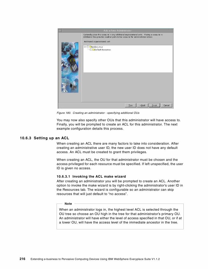
Figure 180. Creating an administrator - specifying additional OUs
You may now also specify other OUs that this administrator will have access to. Finally, you will be prompted to create an ACL for this administrator. The next example configuration details this process.
10.6.3 Setting up an ACLWhen creating an ACL there are many factors to take into consideration. After creating an administrative user ID, the new user ID does not have any default access. An ACL must be created to grant them privileges.
When creating an ACL, the OU for that administrator must be chosen and the access privileged for each resource must be specified. If left unspecified, the user ID is given no access.
10.6.3.1 Invoking the ACL make wizard After creating an administrator you will be prompted to create an ACL. Another option to invoke the make wizard is by right-clicking the administrator’s user ID in the Resources tab. The wizard is configurable so an administrator can skip resources that will just default to “no access”.
When an administrator logs in, the highest level ACL is selected through the OU tree so choose an OU high in the tree for that administrator’s primary OU. An administrator will have either the level of access specified in that OU, or if at a lower OU, will have the access level of the immediate ancestor in the tree.
Note
216 Extending e-business to Pervasive Computing Devices Using IBM WebSphere Everyplace Suite V1.1.2

Figure 181. OU window of the ACL make wizard
After invoking the ACL make wizard, you will be prompted to choose an OU. Notice the Tips button.
Figure 182. Resource type selection in the ACL make wizard
Now select the resource types this administrator will have access to.
Chapter 10. Wireless Gateway administration 217

Figure 183. Configuring access levels to a chosen resource in the ACL make wizard
For each chosen resource type, choose the access level of this administrator. Notice the check boxes on the bottom of the window; these boxes are parameters to that specific resource. These will become enabled depending on the level of access given to the administrator. Some resources may not have any check boxes.
10.7 Troubleshooting tips
The following are some common problems and solutions for using the Wireless Gatekeeper.
What if things are not enabled? Each list of resources has a set of buttons across the bottom of the window. Some buttons are grayed out. Why?
• The administrator may not have selected the appropriate number of resources (for example, when you delete options multiple resources must be selected, but when you see properties a single resource can be selected).
• The administrator may not have been given permission to perform the action (to see the currently logged-in administrator’s access authority, click File->Access Control Lists and then find the OU and Resource in question).
What if some of the Tasks in the left pane are greyed out?
• The tasks are visible only if you have the appropriate access authority in at least one ACL.
• The administrator does not receive the ACLs until he or she is logged in; it is possible you are not logged in.
• Some tasks are visible without logging in (for example, the “How Do I? questions related to logging in and using the Gatekeeper).
• If the administrator is logged in, it is possible he or she does not have the appropriate access level for that task. Click File->Access Control Lists.
218 Extending e-business to Pervasive Computing Devices Using IBM WebSphere Everyplace Suite V1.1.2

What if the left pane is empty? An administrator is logged on but what if there is nothing visible in the left pane of the Resources tab?
• Most likely the administrator does not have read access to any OUs.
• Check the administrator’s ACLs by clicking File->Access Control Lists.
• It is possible that the LDAP server is not up, or was not up when the Gateway started. Check with an administrator who has access to the LDAP server.
• It is possible that the LDAP configuration is not correct. Check with an administrator who has access to the LDAP server.
10.8 Need more help?
The Gatekeeper provides several helpful features:
• The How Do I? option in the Tasks pane discusses common tasks that can be performed by the Gatekeeper.
• If you right-click a resource, choose What Is? from the menu to learn more about a resource.
• Clicking Help -> Help provides a thorough discussion of how to use the Gatekeeper.
• Online documentation and the latest updates for the Gatekeeper are available by clicking Help -> Product Support Site.
• During certain wizards there is also a Tips button that displays a floating context-sensitive help window.
• The Find a resource task and the Find button at the bottom of the left pane were designed to search through complex OU configurations. Limiting the searches by OUs or resource type is recommended for best performance.
10.9 Sample WAP Gateway configuration
In this section we show you the WAP configuration used in the Wireless Gateway scenario as described in 9.9, “A sample WAP scenario” on page 202. In the WAP Gateway window you can administer the secure and unsecure WAP browsing ports as well as the HTTP proxy address and port that will typically be the Authentication Server. In this window you can also enable HTTP redirection in the WAP Gateway (see Figure 184).
Chapter 10. Wireless Gateway administration 219

Figure 184. WAP Gateway window
Figure 185 on page 221 shows the WAP Gateway security options. The verification type (user authentication) and the support for HTTP cookies is configured in this window.
Note: Since WAP phones do not support cookies, you will need to enable HTTP cookie support in the WAP Gateway if required by your applications.
The check box to allow an HTTP secure connection (HTTPS) only when using a secure WAP connection (using WTLS) is selected when you want to make sure that both connections must be protected (secured). However, you should be aware that the secure connection is not end-to-end (WAP device to application server) but it needs to be divided into two secure connections (WTLS and SSL).
The key exchange suites are also selected in this window. Some of these schemes do not require the use of a certificate (anonymous) and therefore are subject to man-in-the-middle attacks.
For better security, a public key of at least 1024 bits is highly recommended. This key is used to protect (encrypt) the symmetric key for bulk encryption (data encryption). Diffie-Hellman and RSA algorithms (based on prime numbers) are supported for key exchange.
220 Extending e-business to Pervasive Computing Devices Using IBM WebSphere Everyplace Suite V1.1.2

Figure 185. WAP security
For actual data encryption using the previously exchanged symmetric key, several algorithms are supported, for example RC4, RC5, DES and others. For more details about public key, data encryption and certificates see Chapter 11, “Secure Sockets Layer (SSL)” on page 225 and Chapter 12, “Wireless Transport Layer Security (WTLS)” on page 251.
Figure 186 shows the Secure Sockets Layer (SSL) related configuration. Here you specify the file names for the key database (certificates are stored in this file) and for the password to access this database.
Figure 186. WAP Secure Sockets Layer (SSL) window
Chapter 10. Wireless Gateway administration 221

Figure 187 shows a sample Wireless Session Protocol (WSP) parameters for the WAP connections.
Figure 187. WAP Wireless - sample WSP parameters
Figure 188 shows a sample Wireless Transaction Protocol (WTP) parameters for the WAP connections. In this window you can enable packet segmentation and reassembly. In most cases, these options are required in WAP connections.
Figure 188. WAP Wireless - sample WTP parameters
Figure 189 shows the WTLS parameters, such as the key refresh frequency, session cache maximum size, and the connection cache maximum size. For information about WTLS, see Chapter 12, “Wireless Transport Layer Security (WTLS)” on page 251.
222 Extending e-business to Pervasive Computing Devices Using IBM WebSphere Everyplace Suite V1.1.2

Figure 189. WAP Wireless Transport Link Security (WTLS) parameters
A sample window showing the WAP Gateway broker parameters is shown in Figure 190.
Figure 190. WAP Gateway broker parameters
Chapter 10. Wireless Gateway administration 223

224 Extending e-business to Pervasive Computing Devices Using IBM WebSphere Everyplace Suite V1.1.2

Chapter 11. Secure Sockets Layer (SSL)
In this chapter, we present an overview and cover some of the common terms and concepts associated with Secure Sockets Layer (SSL). We then focus on SSL security available in the IBM WebSphere Everyplace Suite components and describe the basic steps required to enable this important security feature.
11.1 Overview
Secure Sockets Layer (SSL) is the standard for security in the Internet. A new standard called Transport Layer Security (TLS) will be replacing SSL. However, TLS is based on SSL protocols, specifically the handshake and record protocol originally implemented by SSL.
IBM WebSphere Everyplace Suite includes the following SSL-enabled components:
• IBM HTTP Server (IHS)
• Edge Server - Caching Proxy (WTE)
• Everyplace Wireless Gateway (EWG)
• LDAP directory services
11.1.1 Symmetric cryptography versus asymmetric cryptographyThere are two kinds of key-based cryptography, symmetric encryption and asymmetric encryption.
11.1.1.1 Symmetric cryptographyIn symmetric cryptography, also known as shared-key cryptography, the encryption and decryption are performed with exactly the same key. This is fast cryptography, but the disadvantage is that the key must be exchanged in a very secure way, which might not be easy in many situations, especially if you have many secret keys for many secured channels. Symmetric cryptography is illustrated in Figure 191.
Figure 191. Symmetric cryptography
Some example of symmetric encryption ciphers are DES, RC4, RC5, 3DES, and many others. The key length as well as the chosen cipher method used by these ciphers are critical factors. For example, DES implements a key of 56 bits, but in order to prevent a brute force attack where all possible keys can be potentially tested, larger key lengths, such as 128-bit keys, can be used.
The same key is used for encryption and decryption...
My credit cardnumber is...
Encrypt Decrypt71!^$U'Adx^3!!sk!Wg|'vr^kq!6BB!!
My credit cardnumber is...
© Copyright IBM Corp. 2001 225

11.1.1.2 Asymmetric cryptography Also known as public-key cryptography, asymmetric cryptography uses a key pair for encryption and decryption (a private key and its associated public key). In public-ey encryption, the public key is derived from the private key, but it is mathematically impossible to derive the private key from the public key.
A message encrypted with one of the two keys can only be decrypted with the other key. Asymmetric cryptography is more processing intensive than the symmetric cryptography algorithms. The amount of computing power required is based on the size of the encryption key utilized. The larger the key, the stronger the security we get, but the more time it takes to execute the algorithms.
By far the most common public-key algorithm in use nowadays is RSA, which is based on prime numbers and the fact that it is virtually impossible to factor very large numbers. Asymmetric cryptography is illustrated in Figure 192.
Figure 192. Asymmetric cryptography
Public keys may be distributed freely without any security risk. However, public keys do not provide authentication by itself. Then anyone can present his own public key and the receiver could mistakenly trust that it is the original sender public key. Instead, the public key is distributed using trusted certificates for authentication of the sender.
In SSL, public-key encryption is used as follows:
• The public key is used to encrypt a symmetric key. This allows an easy way to exchange a key for bulk encryption. That is, the sender encrypts a random key that can only be decrypted by the receiver with its private key.
• The private key is also used to encrypt a hash value (or fingerprint) of a digital certificate. The result is known as a digital signature (see 11.1.2, “Digital certificate” on page 227). This way, anybody can verify the digital signature by obtaining the hash value of the certificate, applying the public key of the sender to the encrypted hash value, and comparing the results. If both values match, the digital signature is valid and the sender is authenticated.
Symmetric encryption is fast and it is used for bulk encryption, that is encryption of large amounts of data. However, symmetric encryption does not help you to exchange shared keys (key management).
Note
Public Key Cryptography
My credit cardnumber is...
Encrypt Decrypt
My credit cardnumber is...
71!^$U'Adx^3!!sk!Wg|'vr^kq!6BB!!
Encryption and decryption use different keys,a public key and a private key.
Decrypt
Private Public
Encryptfng*!j+=lkAE0!^uQ!Pdd@j%!$KK^!!Tx
226 Extending e-business to Pervasive Computing Devices Using IBM WebSphere Everyplace Suite V1.1.2

The hash value is obtained by applying a one-way algorithm to the certificate for data integrity. The most popular algorithms are MD5 and SHA-1.
Note: In SSL, the entity signing the certificate is called the Certificate Authority or simply the CA (see 11.1.3, “Certificate Authority (CA)” on page 227).
11.1.2 Digital certificateA digital certificate is an electronic document like the passport document we use in common life. It certifies an entity identity. A digital certificate is a digital document that validates the identity of the certificate owner. Digital certificates are illustrated in Figure 193.
Figure 193. Digital certificate
11.1.3 Certificate Authority (CA)A Certificate Authority (CA) is a trusted party that creates digital certificates. It is like the passport office. We all know that a trusted passport office issues passports with real and verified information. If the trusted passport office discovers any incorrect information, the passport office can cancel the passport and inform all parties to ignore the passport as a trusted proof of identity.
For example, if the passport office did not have public credibility, no one would accept a passport as an identification document.
Makes owner's public key available to othersMust be issued by a trusted Certificate Authority (CA)Set the scene for Public Key Infrastructure (PKI)
Owner's public key
Owner's distinguishedname, e.g. IBM-ITSO
Certificate Authority'sdistinguished name
Encrypted messagedigest
CA'sprivate key
Chapter 11. Secure Sockets Layer (SSL) 227

Figure 194. For travelers the Certificate Authority (CA) is the passport office
11.1.4 Trusted rootThe trusted root provides users with Certificate Authority contact details. This enables the user (client or server) to contact the Certificate Authority to validate certificates. In our example, the trusted root is the passport office, which anyone can access to verify a passport validation or someone’s identity.
11.1.5 Certificate Revocation List (CRL)A Certificate Revocation List (CRL) is a list of invalid certificates. It is basically the black list for certificates we should not accept. A CRL is usually maintained by the CA, which keeps it up to date and makes it available to the appropriate entities.
11.1.6 Digital signatureA digital signature is a method used to prove an entity’s identity and check that transferred data has not been modified (data integrity).
Figure 195. Using digital certificates and signatures to verify identity
I am going to set up a fakesite to sell books. No one
will ever know.I'll make millions!
This site does not have acertificate from a trustedsource. I will not take the
risk of giving my creditcard number to an unknown
organization.
AWARDAWARDCERTIFICATECERTIFICATE
Digital Certificatewith
Digital Signature
228 Extending e-business to Pervasive Computing Devices Using IBM WebSphere Everyplace Suite V1.1.2

11.1.7 Public Key Infrastructure (PKI)PKI provides the basis for practical use of public-key cryptography and X.509 digital certificates. PKI has been used in many protocols, such as Secure Sockets Layer (SSL), Secure Multimedia Internet Mail Extensions (S/MIME), IP Security (IPSec), Secure Electronic Transactions (SET), and Pretty Good Privacy (PGP), among others.
The core components of a PKI include:
• The End-Entities (EE)
An End-Entity is defined as a user of PKI certificates and/or end-user system that is the subject of a certificate.
• The Certificate Authority (CA)
• The Certificate Repository (or key database)
The Certificate Repository is a store of issued certificates and revoked certificates in a CRL.
• The Registration Authority
The Registration Authority (RA) is an optional component in a PKI. In some cases, the CA incorporates the role of an RA. Where a separate RA is used, the RA is a trusted End-Entity certified by the CA, acting as a subordinate server of the CA. The CA can delegate some of its management functions to the RA. For example, the RA may perform personal authentication tasks, report revoked certificates, generate keys, or archive key pairs. The RA, however, does not issue certificates or CRLs.
• Digital certificates in standard X.509 format
11.1.8 Security methods and standardsIn this section we will cover symmetric cryptography, asymmetric cryptography, certificates data types and digital signatures techniques.
11.1.8.1 Symmetric cryptography algorithmsSome of the most frequently used algorithms for bulk encryption in SSL are:
• DES: Data Encryption Standard (DES) was developed by IBM in 1975. DES is the de facto industry standard for cryptography systems and is the world’s most commonly used encryption mechanism. DES is a symmetric block cipher that uses a 56-bit private key (plus 8 bits for key integrity checking) and operates on 64-bit blocks of data.
• 3DES: This cipher is also known as Triple DES. In Triple DES, each block of data is processed three times with at least two different keys. With Triple DES, we have three sub-keys. The Triple DES key has 56 bits per sub-key, which means we can have up to (56 x 3)-bit keys.
• RC4: RC4 is a symmetric stream cipher that can use up to 2048-bit keys.
• RC5: An enhanced version of RC4.
11.1.8.2 Asymmetric cryptographyThe only public-key algorithm used in SSL is RSA. However, in some implementations, outside SSL, a Diffie-Hellman algorithm can also be used to exchange a symmetric key.
Chapter 11. Secure Sockets Layer (SSL) 229

• RSA is an asymmetric cipher used to encrypt messages, such as a symmetric key and hash values to create digital signatures.
• Diffie-Hellman is an algorithm used to exchange a symmetric key. It is not part of standard SSL, since it does not implement the use of digital certificates for authentication.
11.1.8.3 Certificates data formatsThe following data formats can be used to create certificates:
• Base64 is an encoding scheme that converts binary data into 7-bit ASCII. It is typically used to transfer binary data in e-mail applications. It is also used by IKEYMAN to generate the certificate request and by VeriSign to send back the digital certificate in ASCII. This made it easy to send the request using theVeriSign Web site by opening the request file generated by IKEYMAN as a text file and passing the content to the VeriSign request text box. It is also used by VeriSign to send the certificate by e-mail as text in order to cut and paste to an ASCII file. In turn the document is received by IKEYMAN as a new base64-encoded certificate.
Note: IKEYMAN is the utility program used to support SSL certificate management.
• X.509 is an International Telecommunication Union (ITU) recommendation for the format of certificates. X.509 is the most widely used certificate format for PKI. It is used in major PKI-enabled protocols and applications, such as SSL, IPSec, S/MIME, Privacy Enhanced Mail (PEM), or SET.
• Binary Distinguished Encoding Rules, or Binary DER, is used in the X.509 certificate data structure encoding process.
11.1.8.4 Digital Signatures methodsThere are two methods to create to create digital signatures:
• RSA: As mentioned before, RSA is an asymmetric cipher used to encrypt short messages, such as symmetric keys and to create digital signatures. The private key is used to create the digital signature and anybody can verify it using the signer’s public key.
• DSS: Digital Signature Standard is another method for creating digital signatures, but it is seldom used in SSL.
11.1.8.5 Data integrityA hash value (message digest) is a sort of secure checksum of data. Hash algorithms take data as input and produce a fingerprint of the data. The hash operation is not reversible. That is, a message digest (hash value) cannot be turned back to the original data.
Hash or message digest schemes detect any type of document change including data rearrangement and bit transposition. Message digests are used to verify the integrity of documents, to make sure that data has not been modified.
Figure 196 illustrates how hash values (message digest) are created and then encrypted to provide a fingerprint or digital signature.
230 Extending e-business to Pervasive Computing Devices Using IBM WebSphere Everyplace Suite V1.1.2

Figure 196. Message digest secures data integrity
Message digest algorithms, such as MD5 and SHA-1, are used in public-key cryptography to secure data integrity:
• SHA-1: The Secure Hash Algorithm has been adopted as the Federal Information Processing Standard (FIPS). SHA-1 generates 160-bit fingerprints. SHA is similar to MD5 but cryptographically stronger (harder to break) and slower than MD5.
• MD5: The Message Digest algorithm (MD5) is a hash algorithm that generates 128-bit fingerprints. It is slightly faster than SHA-1.
Both MD5 and SHA-1 can be applied to a single character as well as several megabytes of data. The result is the same number of bits as defined above.
11.1.9 SSL tunnelingSSL tunneling refers to establishing a secure channel through the proxy. The proxy only knows user authentication, source, and destination. The proxy has no access to data exchanged between a client and a destination server. Digital certificates are exchanged directly between a client and a destination server.
SSL tunneling is illustrated in Figure 197.
Insecure networkEncryptinput msg + digest
inputmessage
Message DigestAlgorithm
Message digest algorithm produces fixed length "digitalhash"Same algorithm used to validate message received
sender'sprivate key
messagedigest
sender'spublic key
DecryptComparedigests
Chapter 11. Secure Sockets Layer (SSL) 231

Figure 197. SSL tunneling
In the WES environment, the Edge Server - Caching Proxy (WTE), which is part of the IBM WebSphere Everyplace Suite, is a proxy server supporting SSL and SSL tunneling capabilities.
11.2 Secure connections
SSL was developed by Netscape Communications Corp. and is implemented in most Web browsers, including Netscape and Internet Explorer.
As illustrated in Figure 198, SSL adds an additional layer between network protocols and the protocols that are used on the application level. SSL encapsulates TCP/IP sockets so that every application using TCP/IP can use SSL to secure the connections.
Figure 198. SSL layer
Currently, SSL is commonly used to secure communication between TCP/IP applications, such as HTTP and Telnet.
DestinationServer
HTTPS://www.bigserver.com
CERTIFICATECERTIFICATE
ProxyServer
Client
CERTIFICATECERTIFICATE
SSL Tunnel
Enable CONNECTProxy +:443Port 80
myproxy.mycompany.com
SSLMode OnSSLPort 443
www.bigserver.com
Application(s)
(WWW, POP, SMTP, e-mail)
Security Layer (SSL)
TCP/IP Layer
HTTP SMTP LDAP
Application Protocols
Network Protocols
232 Extending e-business to Pervasive Computing Devices Using IBM WebSphere Everyplace Suite V1.1.2

The SSL protocol has functions that make it an excellent method to provide an end-to-end encrypted communication session. This is achieved by supporting the following functions:
• Authentication allows each party to verify the identity of the other if required. Digital certificates are used to provide this function. In SSL V2.0, only server authentication is supported. SSL V3.0 supports both server and client authentication. However, not many products have implemented client authentication, since this is achieved via user ID/password authentication.
• Data encryption and decryption ensures that transmitted data is not readable by any one who doesn’t have the secret key. A secret and shared key is generated for each data exchange session and used to encrypt and decrypt data.
• Data integrity means that the data will be rejected if any changes are detected. This is to ensure that no one can manipulate transmitted data between the sender and receiver.
Table 4 shows the categories of SSL service, the technologies used, and the types of security attacks they protect against.
Table 4. SLL services
SSL uses public-key encryption, symmetric encryption, hashing, digital signatures, and certificates.
The main reasons why SSL incorporates both public-key and private-key cryptography are to improve performance and to simplify key management. Public-key cryptography offers the best security, but it is much slower than private-key cryptography. SSL uses only public-key cryptography (specifically RSA) for session initiation (which includes passing the secret symmetric key needed for private-key cryptography). SSL uses private-key cryptography for all data encryption after establishing the session (bulk encryption). This means that SSL uses the maximum security to pass the secret key and then uses a faster method for all consequent data to be exchanged.
Another important point to know is that when the browser contacts the server, both the browser and the server have to agree on a common cipher that both can use. It is like two people trying to talk to each other. One speaks French and English, and the other person speaks English and Arabic. if they want to speak to each other they must use something they both understand.
This means an IBM WebSphere Everyplace Suite SSL server with large-key-size support does not necessarily mean a higher level of symmetric encryption if the browser doesn’t support it. For example if the server supports 128-bit key encryption and the browser supports only 40-bit encryption, then in this case the 40-bit encryption will be used to encrypt data exchanged between the server and the browser.
SSL Service Technology Protection against
Authentication X.509 Certificates Fake entities
Integrity Message Authentication codes (Keyed hash functions)
Vandals or entities try to corrupt the data
Privacy Encryption People try to read confidential data
Chapter 11. Secure Sockets Layer (SSL) 233

Figure 199. How SSL works
For a complete and detailed description of public key infrastructures, refer to the redbook Deploying a Public Key Infrastructure, SG24-5512.
11.3 Steps to establish SSL server authentication
Server authentication means basically the ability to verify the server identity before supplying critical information, such as credit card details. Users don’t trust providing critical information to a Web site if they can’t verify its identity.
To establish SSL server authentication we need to:
1. Obtain a digital certificate (create or buy a certificate)
2. Use a key management tool (IKEYMAN) to save keys in a keys database
3. Configure the server to enable SSL (using IBM HTTP Server, Edge Server - Caching Proxy and Wireless Gateway)
4. Configure the browser to use the new certificate
Steps 1, 2 and 4 (obtaining a digital certificate, using IKEYMAN, and the browser configurations) are the same for all IBM WebSphere Everyplace Suite components.
The way we configure each component (IBM HTTP Server, Edge Server - Caching Proxy and Wireless Gateway) will be different, as we explain later in this chapter.
11.3.1 Obtaining a digital certificateWe need to get a certificate from a Certificate Authority (CA), which verifies our identity (like applying for a passport). There are three ways to obtain a certificate.
1. Buying a certificate from an external trusted CA provider such as VeriSign.
In this case we buy a signed certificate by submitting a certificate request to a CA provider. This method is similar to going to the passport office to get a passport.
3. The certificate signature ischecked by the browser.
1. A user needs to sendprivate data. For example,a credit card number.
4. The browser confirms thatserver is the one that is
desired and encrypts data.
5. The server decrypts thedata with a negotiatedsession key.
2. The server retrieves acertificate from anauthority the browserrecognizes.
The browser sends HTTPS:// request.
The server certificate is sent back.
The encrypted information is sent
with a negotiated session key.
234 Extending e-business to Pervasive Computing Devices Using IBM WebSphere Everyplace Suite V1.1.2

2. Creating a self-signed certificate.
This is similar to issuing your own passport hoping that others will accept it. In general, this is only good for testing or maybe for a predefined set of clients who trust the certificate signer.
Note: We do not recommend using this type of certificate in a production system.
3. Obtaining a temporary certificate from a CA for testing purposes.
These certificates are normally free of charge.
IBM WebSphere Everyplace Suite modules provide a Java-based graphical user interface application (IKEYMAN) to manage certificates and encryptions keys in a secure manner.
To manage certificates and encryption keys in a secure manner, IBM WebSphere Everyplace Suite components use a secured repository called a key database. A key database is basically a password-protected file that can be used to save root certificates and SSL keys. Creating a key database will be the first step in setting up SSL.
In the rest of this section you will learn how to obtain a digital certificate using IKEYMAN. We will set up the environment to use IKEYMAN, and then we will create self-signed certificates and a certificate request to be sent to a CA.
11.3.1.1 Setting up the Java environmentIKEYMAN is a Java program. To run IKEYMAN, we need to set the JAVA_HOME environment variable to Java jdk_base by executing the following command:
# export JAVA_HOME=/usr/jdk_base
To run the IKEYMAN application, type the following command:
# /usr/bin/ikeyman &
11.3.1.2 Creating a self-signed certificateSelf-signed certificates are good for testing purposes only, because not having a CA involved in the certificate identification is a security risk. Web browsers usually notify users about the new unregistered issuer when accessing a site that uses the self-signed certificate. The user then has the choice of accepting or rejecting the connection to such a server.
The first thing you need to do before using IKEYMAN is to create a key database. You can create a key database by following the steps below:
1. Run IKEYMAN by executing # /usr/bin/ikeyman &. This will load the IKEYMAN Java application.
2. By now the IKEYMAN application is loaded and you can start creating a new key database by selecting Key Database File -> New.
3. In the New pop-up window shown in Figure 200, select the CMS key database file from the Key database type list box and enter the new key database file name and location. Then click OK.
Chapter 11. Secure Sockets Layer (SSL) 235
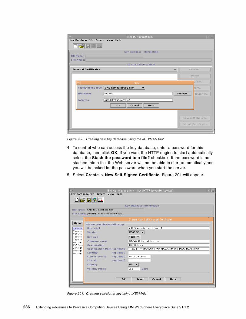
Figure 200. Creating new key database using the IKEYMAN tool
4. To control who can access the key database, enter a password for this database, then click OK. If you want the HTTP engine to start automatically, select the Stash the password to a file? checkbox. If the password is not stashed into a file, the Web server will not be able to start automatically and you will be asked for the password when you start the server.
5. Select Create -> New Self-Signed Certificate. Figure 201 will appear.
Figure 201. Creating self-signer key using IKEYMAN
236 Extending e-business to Pervasive Computing Devices Using IBM WebSphere Everyplace Suite V1.1.2

6. Fill in all information, then click OK to create and save the certificate. Information provided in the resulting window, shown in Figure 202, will be available to anyone who accesses the site using this certificate.
Figure 202. Self-Signed certificate details view
11.3.1.3 Using Certificates signed by a CAThe new key database is preconfigured with the root certificate for main external Certificate Authorities operating today. In the following sections, we cover requesting certificates from the Certificate Authority that has a predefined root in the key database.
Requesting a certificate from CA that has a predefined root This section describes the procedure to request certificate from Certificate Authorities whose root certificates are already defined in the key database. Requesting a digital certificate will typically include a fee depending on to which CA you send the request, offers, time and specifications. In our sample scenario, a trial certificate from VeriSign (valid for 14 days for testing only) is used. Real certificates are usually valid for one year; when it expires a new certificate must be obtained.
The steps to request a digital certificate are as follows:
1. Launch the IKEYMAN application and open the key database.
2. Choose Create from the pull-down menu, or from the tool bar select New certificate request.
3. In the Create New Key and Certificate Request window, shown in Figure 203, fill in the information about your certificate,and click OK.
Chapter 11. Secure Sockets Layer (SSL) 237

Figure 203. Creating a certificate request
In order to get a certificate, you have to select a Certificate Authority (CA). Follow the Certificate Authority’s instructions on how to submit the certificate request to the certifier. In our sample scenario, we are using a free trial certificate from VeriSign (https://www.verisign.com). See Figure 204.
238 Extending e-business to Pervasive Computing Devices Using IBM WebSphere Everyplace Suite V1.1.2

Figure 204. VeriSign trial certificate enrollment
When the certificate is received from the Certificate Authority, we can add the certification to the key database using the following steps:
1. Select Personal Certificates from the pull-down menu and click the Receive... button on the right.
2. When the Receive Certificate from a File window appears, enter the certificate’s file name and location and click OK.
3. Highlight the new certificate on the list of Personal Certificates and click View/Edit... The Key information window appears.
4. If not selected, select Set the certificate as the default checkbox. If you have some other software that uses the same key database, this change may affect other applications.
Note: You can store multiple certificates in the database, but only one can be active at a specific time; this is the default certificate.
Chapter 11. Secure Sockets Layer (SSL) 239

Figure 205. VeriSign trial certificate view
Because the predefined Certificate Authorities are known to most browsers in the market, most browsers have these known CAs root-certificate registered in the browsers security configuration. This means the browser can start HTTPS connections out of the box.
Note: For the HTTP Web server, check the httpd.conf file to see if you need to enable SSL. See 11.3.2, “Configuring SSL” on page 241 for details.
Requesting a certificate from an unknown CA (not predefined)When acquiring a certificate from an unknown Certificate Authority, you need to obtain its root certificate first and store it in the key database. The term “unknown CA” does not mean anything about the reliability or trustworthiness of the CA, but that the CA’s root certificate is not preconfigured in the key database.
Storing the root certificate of the CA The procedure to request and configure a certificate from an unknown CA is basically the same as with well-known CAs. Prior to obtaining the certificate, you have to get the root certificate of the CA. The CA provides the information on how to obtain it. The root certificate must be stored in the key database before the certificate.
1. Start the IKEYMAN application and open your key database. Select Signer Certificates from the pull-down list.
2. Click the Add... button to add the CA’s root certificate from a file.
3. On the pop-up window, verify that the file type is base64-encoded ASCII data. Fill in the location and file name of the certificate file.
4. Click OK to mark that the certificate is trusted and to store it. After completion, the new root certificate will show up in the Signer Certificates list. The root certificate is now available to every certificate you intend to include in this key database.
240 Extending e-business to Pervasive Computing Devices Using IBM WebSphere Everyplace Suite V1.1.2
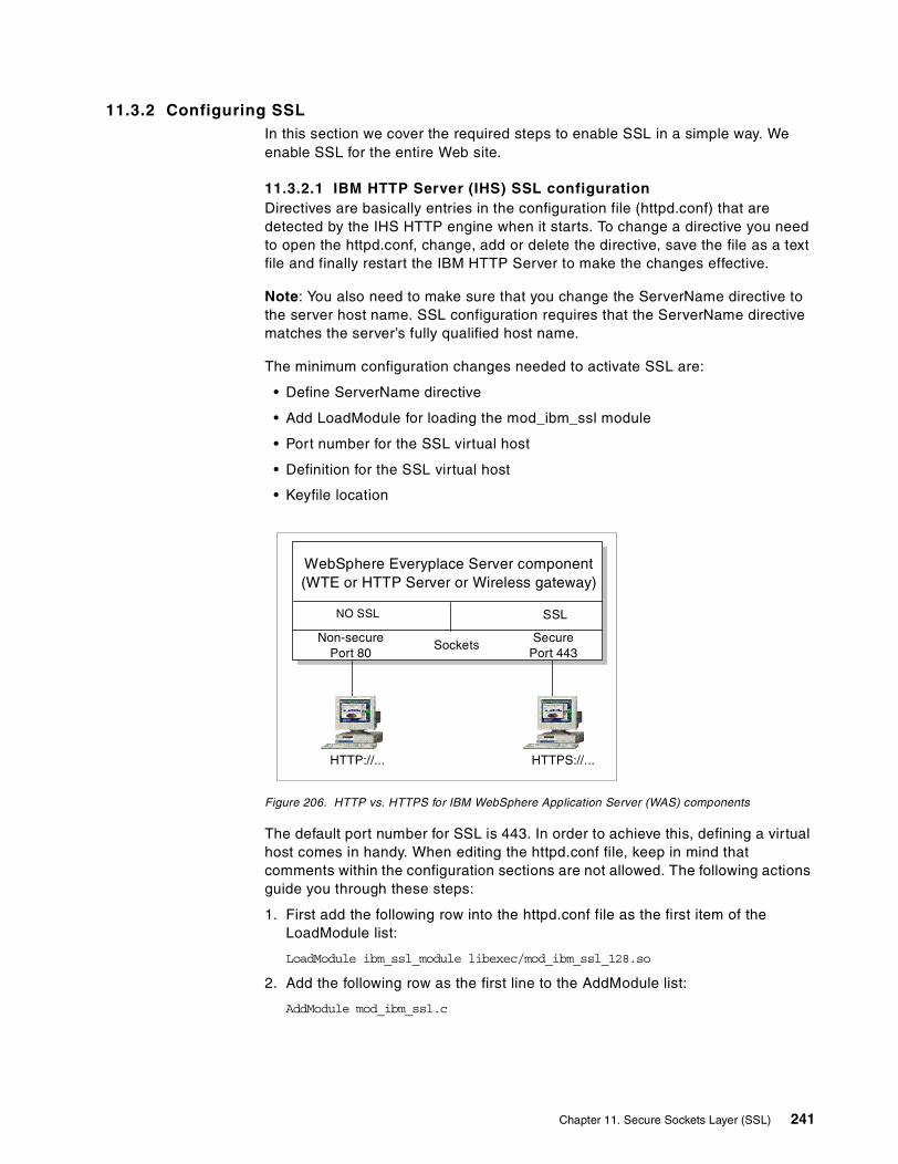
11.3.2 Configuring SSLIn this section we cover the required steps to enable SSL in a simple way. We enable SSL for the entire Web site.
11.3.2.1 IBM HTTP Server (IHS) SSL configurationDirectives are basically entries in the configuration file (httpd.conf) that are detected by the IHS HTTP engine when it starts. To change a directive you need to open the httpd.conf, change, add or delete the directive, save the file as a text file and finally restart the IBM HTTP Server to make the changes effective.
Note: You also need to make sure that you change the ServerName directive to the server host name. SSL configuration requires that the ServerName directive matches the server’s fully qualified host name.
The minimum configuration changes needed to activate SSL are:
• Define ServerName directive
• Add LoadModule for loading the mod_ibm_ssl module
• Port number for the SSL virtual host
• Definition for the SSL virtual host
• Keyfile location
Figure 206. HTTP vs. HTTPS for IBM WebSphere Application Server (WAS) components
The default port number for SSL is 443. In order to achieve this, defining a virtual host comes in handy. When editing the httpd.conf file, keep in mind that comments within the configuration sections are not allowed. The following actions guide you through these steps:
1. First add the following row into the httpd.conf file as the first item of the LoadModule list:
LoadModule ibm_ssl_module libexec/mod_ibm_ssl_128.so
2. Add the following row as the first line to the AddModule list:
AddModule mod_ibm_ssl.c
Non-securePort 80
SocketsSecure
Port 443
WebSphere Everyplace Server component(WTE or HTTP Server or Wireless gateway)
SSL
HTTP://... HTTPS://...
NO SSL
Chapter 11. Secure Sockets Layer (SSL) 241

3. Add the port number for the virtual server just below the Listen 80 statement. The default port number for SSL is 443.
Listen 443
4. Add the following text block to the end of the httpd.conf file:
<VirtualHost :443>SSLEnableSSLClientAuth none</VirtualHost>
5. Save the file and restart the IBM HTTP Server:
# apachectl stop then #apachectl start
The SSL timeout directives can be used to cache the SSL session IDs. Caching SSL session IDs reduces the expense of repeating SSL handshaking.
11.3.2.2 Edge Server - Caching Proxy server configurationEdge Server - Caching Proxy (WTE) Version 3.5 is a caching proxy supporting secure connections (SSL) as well as SSL tunneling capabilities.
Caching Proxy is used in a variety of ways. One of these is a scenario that we can place in Caching Proxy as a proxy server between one or more content servers and the Internet. It accepts requests from Internet clients for content stored on the proxy server's domain. Using a proxy this way is called reverse-proxy.
Note: When you configure a WES Authentication Server in AP mode, it requires that the underlying WTE be configured as a reverse proxy. See 6.2, “Sample scenario: Authentication Proxy (AP)” on page 113 for details.
When a proxy server is configured for reverse proxy, it appears to the client to be the origin (content) server; the client is not notified that the request has been sent to another server. Therefore, for clients using HTTPS, this proxy is the SSL server. Caching Proxy 3.5 uses the IKEYMAN tool and has SSL support features.
Caching Proxy can handle HTTPS (between the WTE and the client), break the channel, then pass the channel as HTTP (between the proxy and HTTP server).
WTE can also be the SSL client for the content servers. As an example if the content server is IBM HTTP Server and enabled as an SSL server, Caching Proxy can connect HTTPS secure channels between the SSL client (Caching Proxy) and SSL server (IBM HTTP Server).
Note: A secure SSL connection can also be established between the Everyplace Wireless Gateway (EWS) and WTE. See 9.8, “Gateway security scenarios” on page 198 for details.
The httpd.conf.sample.ssl file that ships with the SSL module of the IBM HTTP Server contains a wealth of information in the form of comments that further explain how to setup SSL, including client authentication.
Note
242 Extending e-business to Pervasive Computing Devices Using IBM WebSphere Everyplace Suite V1.1.2

Figure 207. WTE SSL capabilities
The Caching Proxy’s ability to be an SSL server for the Internet browser and an SSL client for the content server(s) facilitates IBM WebSphere Everyplace Suite end-to-end SSL security. Terminating the secure SSL connection in the Caching Proxy node is not necessarily a risk, because physical access to Caching Proxy is limited to people who can access WebSphere Everyplace Suite content servers (physically). In WebSphere Everyplace Suite this is needed as the first communication contact for both HTTP and HTTPS clients, which pass information in clear text to other WebSphere Everyplace Suite components using HTTP or secured data using HTTPS.
Caching Proxy uses the certificate generated by IKEYMAN and works as a proxy for both HTTPS and HTTP. This makes it an SSL-aware proxy that can also work as both an SSL server and an SSL client.
Note that Caching Proxy works as an SSL server in reverse proxy mode only. Caching Proxy also has the ability to pass SSL traffic without having access to the exchanged data, just as a normal proxy. This is called SSL tunneling.
In summary, Caching Proxy can work:
1. As a proxy with SSL server (Server Authentication) features in reverse proxy mode.
2. As an SSL client to WebSphere Everyplace Suite domain application servers.
3. As a normal proxy (without any SSL capabilities). In this case, you may need SSL tunneling to pass SSL-secured channels.
Edge Server - Caching Proxy SSL server configurationTo enable Edge Server - Caching Proxy SSL features, you need to change SSL directives. Directives are basically entries in the configuration file (/etc/ibmproxy.conf) that are detected by the Edge Server - Caching Proxy HTTP engine when it starts. To change an SSL directive, you need to open the /etc/ibmproxy.conf file, change and save the file as a text file called /etc/ibmproxy.conf, and finally restart the Edge Server - Caching Proxy to make changes effective.
The minimum configuration changes needed (beside obtaining a certificate and key management discussed earlier in chapter) to activate SSL is to change the SSLEnable directive option to on (initial configuration file setting is off) as follows:
SSLEnable on
W TE
SSLServer
Client HTTPServer
HTTPS HTTPS
Chapter 11. Secure Sockets Layer (SSL) 243

Optionally, you can specify the time-out values for SSL sessions, and determine if you want to cache the contents of secure requests. You will then save the /etc/ibmproxy.conf file and restart the Edge Server - Caching Proxy.
Note: To stop Edge Server - Caching Proxy, use the stopsrc command:
stopsrc -s ibmproxy
To start the server, enter:
startsrc -s ibmproxy
For details on how to install and configure Edge Server - Caching Proxy, refer to the online Edge Server - Caching Proxy reference manuals.
Edge Server - Caching Proxy SSL tunneling configurationSSLTunneling directive can be used to allow SSL tunneling to any port on the destination host, for example SSLTunneling off .
The initial configuration file setting to enable SSL Tunneling is SSLTunneling on .
11.3.2.3 Wireless Gateway SSL configurationYou can configure the Wireless Gateway to use Secure Sockets Layer (SSL) communications between the Wireless Gateway and the following servers:
• Web servers (back-end application servers) using secure HTTPS connections (for WAP clients). When a WAP client requires an HTTPS connection to a Web server, the Wireless Gateway decodes the WTLS protocol request and opens an SSL connection on behalf of the WAP client. See Chapter 12, “Wireless Transport Layer Security (WTLS)” on page 251.
• Authentication Server running as a plug-in of WTE. Actual SSL support is provided by WTE.
• A secure connection can be established with the Wireless Gatekeeper for EWG administration.
For example, in the WAP Gateway, after using IKEYMAN to obtain and manage certificates you need to configure the Wireless Gateway as follows:
1. Using the Wireless Gatekeeper, configure cipher SSL options for WAP clients as shown in Figure 208.
244 Extending e-business to Pervasive Computing Devices Using IBM WebSphere Everyplace Suite V1.1.2

Figure 208. Security options configuration
2. Point to the key database created using IKEYMAN, enter the key database password, and define SSL time-outs for SSL Version 2 and SSL Version 3, as shown in Figure 209.
Figure 209. Wireless gateway SSL configuration
Chapter 11. Secure Sockets Layer (SSL) 245

11.3.2.4 LDAP directory servicesIBM WebSphere Everyplace Suite and LDAP directory services can be optionally configured to support Secure Socket Layer (SSL). You can use SSL to provide strong authentication as well as data encryption of LDAP messages that flow between the client and the LDAP server.
In 11.3, “Steps to establish SSL server authentication” on page 234 we described how to create certificates and manage the key database using the IKEYMAN tool program. For LDAP secure connections, a similar procedure is followed using the same interface and same key database. LDAP SSL service on AIX comes with the IKEYMAN program (called ikmgui). This tool is provided by the gskrf301 fileset (shipped in the Bonus Pack) that is a prerequisite of both client and server daemons used by AIX to use LDAP for authentication with an SSL connection. The SSL key creation must be performed first on the LDAP server and then on every LDAP client.
Note: If more than one LDAP server is needed for better availability, we suggest you create a different key for each server.
For LDAP secure connections, once you have created the key on the server and have extracted the certificate, you need to act on the client. As a first step, you need to create a client key database, following the same process described earlier using IKEYMAN (or ikeygui).
After creating key databases for the server and client using IKEYMAN as described earlier in this chapter, you can use the key database with the mksecldap command to enable the machine to ask for AIX user information from the LDAP server using SSL security. If you have more clients, you can execute the same the steps on each client or copy the client key database to each client machine and reuse it for each mksecldap command.
The mksecldap commandThe mksecldap command provides both client and server configuration in order to use LDAP for security authentication and data management. The syntax for server configuration is:
mksecldap -s -a adminDN -p adminpasswd {-d ldapaixdn}\{-k ssl key file path -w ssl key password}The syntax for client configuration is:mksecldap -c -h hostlist {-d ldapaixdn} {-u [ALL|userlist]} \-a adminDN -p adminpasswd \{-k ssl key file path -w ssl key password } \{-t maxtimeout} \{-C <cache size> } {-P <number of thread>}The switches are defined as follows:-c Client configuration.-s Server configuration.-a Administrator’s user name in distinguished name format.-p Administrator’s password.-d Distinguished name of AIX security information subtree. If not specified,the default cn=aixsecdb is used.-k Path to the SSL key file.-w Password needed to access SSL key file.-h List of the LDAP servers that provide AIX security data.
246 Extending e-business to Pervasive Computing Devices Using IBM WebSphere Everyplace Suite V1.1.2

-u When used on a client, it updates the local /etc/security/user file in orderto define LDAP-provided authentication. If an ALL keyword is provided, all AIXusers will be authenticated using LDAP.-t Time out on LDAP request. If time out occurs, local files are used forauthentication.-C Size of local LDAP data cache used by secldapclntd.-P Number of threads created secldapclntd.
On the server, this command configures both the LDAP and DB2 databases. An LDAP suffix is used to identify the data in cases where other instances of LDAP exist. The LDAP database is populated with all the users defined on the server and their related information.
On the client, this command creates the /etc/security/ldap/ldap.cfg file that contains the needed data to connect to the LDAP servers and starts the secldapclntd daemon that receives all the AIX security command requests and forwards them to the LDAP servers. The command also updates the /etc/security/user file to define which users must use LDAP authentication when the -u switch is used.
For example:
mksecldap -s -a cn=root -p rootpwd -k /etc/keyfile -w sslpwd
The mksecldap command takes care of configuring LDAP, and LDAP methods configure DB2 without interfering with existing LDAP configuration or data. Since many DB2 operations are required, it may take several minutes to complete.
When the command finishes, LDAP is ready to provide AIX user information. Initially, the database contains only the users and groups defined in the server machine.
The configuration of the server part of LDAP does not make the RS/6000 a client of the LDAP database. In order to make the machine access the LDAP server, an explicit client configuration must be made.
11.4 SSL Client authentication
Client authentication is an option supported by SSL Version 3.0. It is not commonly used unless there is a particular reason. It basically verifies the client (browser) certificate, before allowing the client to connect to the server. A client certificate is a binary file that has the information about its owner in X.509 certificate format.
The need for client authentication and the level of identification depends greatly on the needs of Web site owners. For example, the owner of a Web site that needs to be very certain about the identity of the individuals who have access to its Web page might choose to run its own CA software and issue the certificates according to its own policies. A financial institute would probably require application by person and a handwritten signature before it issues a certificate to the customer.
Note: In IBM WebSphere Everyplace Suite, the SSL client authentication is supported by IBM HTTP Server component. In general in the WES environment, clients are authenticated via user ID and password using the RADIUS server.
Chapter 11. Secure Sockets Layer (SSL) 247

Figure 210. Client authentication can be optionally used when using SSL Version 3.0
In WES, the client is authenticated by the Authentication Server; using SSL client authentication adds unneeded complexity to the authentication process and increases the network traffic (and thus server load). Therefore, SSL client authentication should only be used if specifically required for special cases. Client authentication details can be found in Chapter 6, “User authentication” on page 109.
IBM HTTP Server has three levels of SSL client authentication:
Required If used, the IBM HTTP Server will limit access to users with certificates that are signed by a trusted CA and valid.
Optional The optional value causes the IBM HTTP Server to ask for the client certificate, but it is not necessarily required. The level of access will depend on having the certificate.
None No client certificate is needed to access the server (default).
11.5 Configuring the browser to add a new trusted root
In order to establish a secure connection using SSL you will connect to the server using HTTPS instead of HTTP. This can be done by simply typing a new URL, which in our case uses the server host name. The moment the browser detects a secure connection to an undefined authority, it will advise you that it does not recognize the authority that signed the server certificate.
CERTIFICATECERTIFICATE
AUTHORITYAUTHORITY
DigitalPassport
Verifies certificates...
Server Authentication:Client authenticatesthe server identity.Client Authentication:Server authenticates theclient identity.Identity verified bycontacting the certificateauthority.Web
Server
Internet
WebBrowser
Owner:Amir
Issued by:Verisign
Owner:IBM ServerIBM Corp.
Issued by:Verisign
Client identityauthenticated
Server identityauthenticated
The Web server accepts the client certificate only if it is signed by a CA whose root key is marked as a trusted root in the server’s key database. The CA’s root key is marked trusted when the certificate is listed under the signer certificates.
Note
248 Extending e-business to Pervasive Computing Devices Using IBM WebSphere Everyplace Suite V1.1.2

11.5.1 Using a self-signed certificateThe self-signed certificate can be created using the IKEYMAN tool. When the URL indicates the HTTPS protocol, the browser immediately starts a new site certificate wizard. After the new certification wizard starts, you can click More Info... to look at the certificate information provided by the Certificate Authority.
Figure 211. Netscape new certificate wizard
After reading the certificate, you have the choice to accept the connection for this time only, reject it or add the certification root as a trusted authority as illustrated in Figure 212.
Figure 212. New certificate acceptance or rejection
Chapter 11. Secure Sockets Layer (SSL) 249

11.5.2 Using a VeriSign free trial certificateIn this scenario we access a server using a VeriSign trial certificate. Note that the trial certificate must be imported to all browsers. Internet Explorer starts the new certificate wizard when it detects a new certificate (see Figure 213).
Figure 213. Importing a root certificate
Note: When using a real VeriSign certificate, you will not do this process, because the VeriSign trusted root is predefined in Netscape and IE browsers.
250 Extending e-business to Pervasive Computing Devices Using IBM WebSphere Everyplace Suite V1.1.2

Chapter 12. Wireless Transport Layer Security (WTLS)
In this chapter, we present an overview of the Wireless Transport Layer Security (WTLS) implementation used to secure WAP connections in the WAP Gateway provided in the Everyplace Wireless Gateway.
WTLS is a secured data delivery protocol that enables secure data to be delivered to hand-held digital wireless devices, such as mobile phones (WAP phones). In this chapter we include an overview and security considerations about WAP secure connections in the IBM WebSphere Everyplace Suite environment.
12.1 Why WTLS?
WTLS’s primary goal is to provide privacy, data integrity, and authentication for WAP applications when invoked from devices such as mobile phones. There are two main reasons for using WTLS:
1. Need for a security layer: Complete end-to-end security is not provided by the mobile network. Although some mobile phone companies encrypt data while transmitted in the air, this does not guarantee security in that specific encrypted segment.
2. Need for a lightweight security protocol: Secure Sockets Layer (SSL) cannot be used in wireless environment for the following reasons:
a. The mobile phone equipment has limited processing power and memory.
b. Wireless networks are low in bandwidth.
c. The wireless networks require support for datagram and connection-oriented transport layer protocols.
These factors basically created the need for WTLS and are the main difference (besides the key-refresh mechanism) between WTLS and Transport Layer Security (TLS) or SSL.
Note: The WTLS key-refresh mechanism makes it possible to update keys in a secure connection without handshaking. Key refresh makes it harder to attack WTLS, because keys will be invalidated on a timely basis.
In summary, WTLS is an optimized lightweight security layer in the WAP protocol. It secures connections between wireless devices and the WAP gateway (such as IBM Wireless Gateway). WTLS also incorporates datagram support, optimized handshake, and dynamic key refreshing. For more information about connection and connectionless and datagram support in WAP, refer to Chapter 9, “Wireless Gateway” on page 171.
12.1.1 Principles of WTLSAs discussed in Chapter 11, “Secure Sockets Layer (SSL)” on page 225, symmetric or asymmetric ciphers are used when implementing a Public Key Infrastructure (PKI). In symmetric cryptography, the sender and receiver share the same key to encrypt and decrypt data. In asymmetric cryptography, the sender and receiver use two different but related keys to encrypt and decrypt data.
© Copyright IBM Corp. 2001 251

In a Public Key Infrastructure (PKI), asymmetric ciphers are used to prove identity (authentication). The RSA and Diffie-Hellman algorithms are good examples of asymmetric ciphers.
• The RSA (Rivest-Shamir-Adleman) algorithm is an asymmetric cipher used to create digital signatures and data encryption of small messages, such as a symmetric key.
• The Diffie-Hellman algorithm allows the client and server to communicate and transport a shared secret key (symmetric key). It is a key exchange algorithm, which generates a session key for both parties while establishing a secure mechanism to transport the shared key. The algorithm uses each party's unique private value, plus public values.
For a complete and detailed description of Public Key Infrastructure, refer to Deploying a Public Key Infrastructure, SG24-5512.
WTLS is PKI cryptography similar to SSL. As described in Chapter 9, “Wireless Gateway” on page 171, the WTLS layer operates above the transport protocol layer and provides the upper-level layer of the WAP with a secure transport service interface. It encapsulates Wireless Transport Protocol (WTP) layer so that every application using WTP can also use WTLS to secure WAP connections.
Note: When using WTLS, you can have end-to-end security between the WAP protocol endpoints, which are the mobile phone and Wireless Gateway.
Wireless Gateway WTLS supports the RSA public key algorithm (1024, 768 or 512 bits), RSA RC5 symmetric key data encryption (40, 56 and bit), and the hash value (message digest) algorithm SHA-1 (40-80 bit). Refer to Chapter 11, “Secure Sockets Layer (SSL)” on page 225 for more details about these encryption methods.
Similar to SSL, when a WTLS client and server first start communicating they agree on a protocol version, select cryptographic algorithms, authenticate, and use public-key encryption techniques to generate a shared secret.
WTLS can be used on both connectionless and connection-oriented modes:
• Secured connectionless: The secured WAP connection less service uses the WTLS protocol to encrypt the data that flows between the WAP clients and Wireless Gateway. The default port for the secured connectionless protocol is 9202.
• Secure connection-oriented: The secured WAP connection-oriented service uses the WTLS protocol to encrypt the data that flows between the WAP clients and Wireless Gateway. The default port for the secured connection-oriented protocol is 9203. For details, refer to Chapter 9, “Wireless Gateway” on page 171.
12.1.1.1 Record protocolThe record protocol transmits and receives the message data when using WTLS security. Optionally, it can also compress and decompress data.
252 Extending e-business to Pervasive Computing Devices Using IBM WebSphere Everyplace Suite V1.1.2

Figure 214. WTLS protocols
The record protocol receives data from the following four client protocols:
1. Handshake protocol.
This protocol negotiates a secure session to communicate necessary security parameters the client and server can agree on. During this phase, the client and server agree on parameters such as cryptographic algorithms, key size, and authentication. When a WTLS client and server first start communicating, they agree on a protocol version, select cryptographic algorithms, optionally authenticate each other, and use asymmetric encryption techniques to generate a shared secret.
As discussed before, the transformation from SSL to WTLS is based upon the need to support connection and connectionless (datagrams) communications in a low bandwidth environment. To operate within this environment, the WTLS handshake protocol is optimized through dynamic key refreshing.
Dynamic key refreshing allows encryption keys to be updated on a regular and configurable basis during a secure session. This leads to a higher level of security and a considerable saving on bandwidth for the relatively costly handshake procedure.
Figure 215. WTLS handshake protocol
The WTLS handshake protocol involves the following steps:
a. Exchange hello messages to agree on algorithms.
Record Protocol
HandshakeProtocol
ChangeCipherSpec
Protocol
AlertProtocol
User DataProtocol
Client Device(s)
Client HelloW ireless gatewayoperating asW AP gatewaywith WTLScertificate
Tim
e Wireless gateway
Server HelloCertificateServer key exchangeCertificate RequestServer Hello Done
CertificateClient key exchangeVerify CertificateChange Cipher SpecsFinished
Change Cipher SpecFinished
Tim
e
Chapter 12. Wireless Transport Layer Security (WTLS) 253

b. Exchange cryptographic parameters to reach an agreement between the client and server on a pre-master secret value.
c. Exchange certificates and cryptographic information to allow the client and server to authenticate themselves.
d. Generate a master secret value from the pre-master secret and exchanged random values.
e. Provide security parameters to the record layer.
f. Allow the client and the server to verify that both have the same security parameters and that the handshake occurred without tampering.
2. Change cipher specification protocol.
This is a single message protocol. The message sent notifies the other party that subsequent records will be protected under the newly negotiated cipher specification and keys.
3. Alert protocol.
Alert messages transport how critical the messages are and a description of the alert. Alerts use a 4-byte checksum that are calculated from the last record received from the other party. The receiver of the alert should verify that the checksum matches the previously sent message.
4. User data protocol.
Consists of the actual message data.
12.1.1.2 Anonymous handshakeAnonymous handshake can be established using RSA or Diffie-Hellman algorithms. In this case, the client will basically trust the server-claimed identity is always correct and certificates are not used.
• In RSA anonymous, certificates are not used. The client generates a secret value and encrypts it with the server (uncertified) public key.
• In Diffie-Hellman, the server public value is contained in the server key exchange message.
Important: Completely anonymous handshakes (for example, where neither the client nor the server is authenticated) do not protect against the man-in-the-middle attack. That is, attackers may replace the finished messages with fake ones during the handshaking process for creating sessions. However, there are known methods that may protect against man-in-the-middle. For instance, server authentication verifies that the finished messages were not replaced by an attacker.
12.1.1.3 MinicertificateWTLS server minicertificates are like SSL X.509 server certificates. But, WTLS minicertificates are smaller and it is simpler than X.509 to facilitate their processing in resource-constrained handsets.
254 Extending e-business to Pervasive Computing Devices Using IBM WebSphere Everyplace Suite V1.1.2

Figure 216. Digital minicertificates
For a complete and detailed description of Public Key Infrastructures, refer to Deploying a Public Key Infrastructure, SG24-5512.
12.2 WTLS implementation in IBM WebSphere Everyplace Suite
Wireless Gateway is the only component that can handle WTLS among IBM WebSphere Everyplace Suite components. IBM Wireless Gateway comes with AIX tools to generate a minicertificate request, and store the minicertificate (issued by the Certificate Authority). Wireless Gateway also has GUI administration tools to enable WTLS as discussed in this chapter.
Although client authentication is available in the WTLS architecture, it is seldom implemented. At this time it is unclear whether client authentication will be implemented in WTLS. Plus, installing minicertificates on wireless devices is not very visible at this stage.
12.2.1 Steps to establish WTLS server authenticationServer authentication means the ability to verify the wireless gateway identity by the WAP device (server authentication). To establish WTLS server authentication, we need to:
1. Obtain a digital minicertificate (request a certificate).
Makes owner's public key available to othersMust be issued by a trusted Certificate Authority (CA)Set the scene for Public Key Infrastructure (PKI)
Owner's public key
Owner's distinguishedname, e.g. IBM-ITSO
Certificate Authority'sdistinguished name
Encrypted messagedigest
CA'sprivate key
WTLS standard supports two different certificate formats, X.509 certificates (as in SSL) and WTLS minicertificates. However, IBM Wireless Gateway WTLS server supports minicertificates only.
Note
The WAP Gateway in Everyplace Wireless Gateway does not implement WTLS client authentication.
Note
Chapter 12. Wireless Transport Layer Security (WTLS) 255

2. Store keys, CA root, and minicertificates in the IBM WebSphere Everyplace Suite database (repository).
3. Configure the Wireless Gateway server to enable WTLS.
4. Restart the WAP Gateway via SMIT or IBM Wireless Gatekeeper.
5. Configure the mobile phone to use WTLS.
IBM Wireless Gateway uses standard minicertificates issued by any Certificate Authority such as VeriSign (www.VeriSign.com) or FreeCerts (www.FreeCerts.com). IBM Wireless Gateway does not create self-signed certificates. Instead, for testing purposes you will need to create a certificate-request and obtain a trial minicertificates from the Certificate Authorities (a free test version).
Also note that the Wireless Gateway supports both SSL and WTLS. But a different tool is used to manage WTLS. For SSL (as explained in Chapter 11, “Secure Sockets Layer (SSL)” on page 225) all WebSphere Everyplace Suite components use the Java-based tool called IKEYMAN and store certificates and security keys in an IKEYMAN-generated key database (file). All IBM WebSphere Everyplace Suite components (including Wireless Gateway) can use the IKEYMAN tool and the key database for SSL functionality.
For WTLS, an AIX tool (called gw_cert) is provided by the Wireless Gateway only. This tool generates WTLS minicertificates requests and stores the CA certificates in the IBM WebSphere Everyplace Suite database (the key database for WTLS is part of the WebSphere Everyplace Suite schema).
This means there are two different tools and repositories for security for Wireless Gateway. One for SSL (IKEYMAN) and the other one for WTLS (gw_cert).
12.2.1.1 Obtaining a digital certificateWireless Gateway provides an AIX-based application (wg_cert) to manage minicertificates and encryption keys in a secure manner. The IBM WebSphere Everyplace Suite installation creates a schema in the WebSphere Everyplace Suite database, which includes minicertificate and encryption keys information.
If you run wg_cert without any parameters, you will get the following output:
# wg_cert /createUsage: wg_cert /createUsage: wg_cert /deleteUsage: wg_cert /store <privateKey> <serverCert1> [...<serverCertN>] <rootCert>
12.2.1.2 Using certificates signed by a CATo request a minicertificate, run wg_cert /create and enter the requested parameters. For example, when you run this tool, it will generate two files: the first is wtlscsr.p10 and the second file is wtlspn.asc as shown below:
# wg_cert /createEnter your Key Strength (512,768,1024): 512Enter your Country Code: usEnter your Organization: ibmEnter your Server Name: riscwes2Writing Certificate Request to wtlscsr.p10Writing Private Key to wtlspri.asc# ls -altotal 80
256 Extending e-business to Pervasive Computing Devices Using IBM WebSphere Everyplace Suite V1.1.2

-rwxr-xr-x 1 root system 391 Aug 04 14:05 wtlscsr.p10-rwxr-xr-x 1 root system 529 Aug 04 14:05 wtlspri.asc
The file wtlcsr.p10 is the Certificate Signature Request (CSR). This is the file (certificate request) you will send to the trusted Certificate Authority (CA) to be signed. The content will look similar to the following text:
-----BEGIN CERTIFICATE REQUEST-----MIHoMIGTAgEAMC4xCzAJBgNVBAYTAnVzMQwwCgYDVQQKEwNpYm0xETAPBgNVBAMTCHJpc2N3ZXMyMFwwDQYJKoZIhvcNAQEBBQADSwAwSAJBAMh1A6SCnf6S22+0nEddYbqHo/K9nyNiSBjVFb1zvFdPW64SVnCeMKpUQGajUnxDdrlGBPe2wFGTFpESe3j8D7kCAwEAAaAAMA0GCSqGSIb3DQEBBQUAA0EAaTs/XqmPjbrVMgU4/LIazYPY6HqXkAf4CV6tE4etQJyr+OwC80Yz5YuhsCmCfQV2mEzKKCwZc25tVMFtLzNFrw==-----END CERTIFICATE REQUEST-----
The second file (wtlspri.asc) is the private key you should hide safely, to be stored with the minicertificate, as shown later. The file wtlspri.asc content will be similar to the following sample WTLS private key:
----- BEGIN WTLS PRIVATE KEY -----MIIBVQIBADANBgkqhkiG9w0BAQEFAASCAT8wggE7AgEAAkEAyHUDpIKd/pLbb7ScR11huoej8r2fI2JIGNUVvXO8V09brhJWcJ4wqlRAZqNSfEN2uUYE97bAUZMWkRJ7ePwPuQIDAQABAkEAvSxwu5foso61N74indaqm/XV6wa4YBQoJgcx9RB79YfrUId/9I+A//Ol2MZsHfzpCQXuWscFtaQD0lkBfbX/gQIhAORBepv6c6zslBZFleBr+kwssU1eGtRbi4EyD6G+xJPdAiEA4NKJjcZWAK4zgf5uaiGZkdao87sp8XjBHK3u/+maq40CIQDOcja+GvFC5xstZbSgLalN+mJGsqWbik0MBkZDKbLMdQIgNoi7VwmKKQYYdmraK6JU1vxj5SM8TFeHOEa0l5z5qK0CIAqrKw7vz7YRmR06kcylcYMT/O13mBx92D/oB4fmuExO----- END WTLS PRIVATE KEY -----
Next, to get a certificate select a Certificate Authority (CA) such as VeriSign and follow the Certificate Authority’s instructions. In this sample scenario we apply for free trial wireless certificates from FreeCerts (www.FreeCerts.com) and VeriSign (https://www.verisign.com). The enrollment window is illustrated in Figure 217.
Figure 217. VeriSign trial certificate enrollment
The certificate request is illustrated in Figure 218.
Chapter 12. Wireless Transport Layer Security (WTLS) 257

Figure 218. Submitting the request content to VeriSign
When the minicertificate is received from the Certificate Authority (CA), you can save the minicertificate (and keys previously generated) in the WebSphere Everyplace Suite database using the wg_cert /store command, as follows:
# wg_cert /store wtlspri.asc 2000.7.99.99.23.58.28999.txt freecerts_root.txtread in 529 bytes from wtlspri.asc346 bytes of private WTLS certificate (key ServerWTLSCerts/0a_priv) - storedsuccessfully!read in 587 bytes from 2000.7.99.99.23.58.28999.txtread in 628 bytes from freecerts_root.txtpublic wtls certificate (len 388) (key ServerWTLSCerts/0a) - storedsuccessfully!public wtls certificate (len 416) (key ServerWTLSCerts/0b) - storedsuccessfully!Please restart the gateway to use your newly stored certificate chain.#
On the command line, you will enter the root certificate as a parameter, which gives you the freedom to use any Certificate Authority (www.FreeCerts.com is used in this example).
Finally, if needed you can delete a minicertificate using the /delete parameter as follows:
# wg_cert /deleteprivate wtls certificate (key ServerWTLSCerts/0a_priv) - deleted successfully!public wtls certificate (key ServerWTLSCerts/0a) - deleted successfully!public wtls certificate (key ServerWTLSCerts/0b) - deleted successfully!#
258 Extending e-business to Pervasive Computing Devices Using IBM WebSphere Everyplace Suite V1.1.2

12.2.1.3 WTLS configurationAfter defining the WAP server to the Wireless Gateway, you can choose the key exchange suite and cipher suite that define the encryption algorithms used by the WAP services on the WAP server.
You can select options such as RSA anonymous, RSA server certificates, and Diffie-Hellman anonymous as shown in Figure 219.
Note: Anonymous key exchange suites do not require a certificate and therefore, the WAP Gateway is not authenticated by the WAP device using WTLS.
A cipher suite is a combination of a cipher block algorithm with a message digest algorithm. For example, you can choose symmetric encryption RC5 cipher blocks and SHA-1 message digests for certificate integrity as shown in Figure 219.
Note: Based on your security requirements, you can configure the IBM Wireless Gateway to force WTLS and therefore accept mobile secured connections only. This can be done by selecting the Allow HTTPS only when using secure WAP connections check box, as shown in Figure 219. In this case, the WAP Gateway will establish the back-end SSL connection (HTTPS) only when the WAP device has used a secure connection to the WAP Gateway using WTLS.
Although the WTLS secure connection is terminated at the WAP Gateway and an HTTPS connection to a back-end server is established, this option allows you to make sure that both connections are protected (WTLS and SSL).
Note: In the WES environment, the Everyplace Wireless Gateway will typically connect to the Authentication Server.
Figure 219. Key exchange suites
Chapter 12. Wireless Transport Layer Security (WTLS) 259

260 Extending e-business to Pervasive Computing Devices Using IBM WebSphere Everyplace Suite V1.1.2
Appendix A. Special notices
This publication is intended to help IT Specialists to install and configure e-business solutions using the IBM WebSphere Everyplace Suite product. The information in this publication is not intended as the specification of any programming interfaces that are provided by IBM WebSphere Everyplace Suite Version 1.1.2. See the PUBLICATIONS section of the IBM Programming Announcement for IBM WebSphere Everyplace Suite Version 1.1.2 for more information about what publications are considered to be product documentation.
References in this publication to IBM products, programs or services do not imply that IBM intends to make these available in all countries in which IBM operates. Any reference to an IBM product, program, or service is not intended to state or imply that only IBM's product, program, or service may be used. Any functionally equivalent program that does not infringe any of IBM's intellectual property rights may be used instead of the IBM product, program or service.
Information in this book was developed in conjunction with use of the equipment specified, and is limited in application to those specific hardware and software products and levels.
IBM may have patents or pending patent applications covering subject matter in this document. The furnishing of this document does not give you any license to these patents. You can send license inquiries, in writing, to the IBM Director of Licensing, IBM Corporation, North Castle Drive, Armonk, NY 10504-1785.
Licensees of this program who wish to have information about it for the purpose of enabling: (i) the exchange of information between independently created programs and other programs (including this one) and (ii) the mutual use of the information which has been exchanged, should contact IBM Corporation, Dept. 600A, Mail Drop 1329, Somers, NY 10589 USA.
Such information may be available, subject to appropriate terms and conditions, including in some cases, payment of a fee.
The information contained in this document has not been submitted to any formal IBM test and is distributed AS IS. The use of this information or the implementation of any of these techniques is a customer responsibility and depends on the customer's ability to evaluate and integrate them into the customer's operational environment. While each item may have been reviewed by IBM for accuracy in a specific situation, there is no guarantee that the same or similar results will be obtained elsewhere. Customers attempting to adapt these techniques to their own environments do so at their own risk.
Any pointers in this publication to external Web sites are provided for convenience only and do not in any manner serve as an endorsement of these Web sites.
© Copyright IBM Corp. 2001 261

The following terms are trademarks of the International Business Machines Corporation in the United States and/or other countries:
The following terms are trademarks of other companies:
Tivoli, Manage. Anything. Anywhere.,The Power To Manage., Anything. Anywhere.,TME, NetView, Cross-Site, Tivoli Ready, Tivoli Certified, Planet Tivoli, and Tivoli Enterprise are trademarks or registered trademarks of Tivoli Systems Inc., an IBM company, in the United States, other countries, or both. In Denmark, Tivoli is a trademark licensed from Kjøbenhavns Sommer - Tivoli A/S.
C-bus is a trademark of Corollary, Inc. in the United States and/or other countries.
Java and all Java-based trademarks and logos are trademarks or registered trademarks of Sun Microsystems, Inc. in the United States and/or other countries.
Microsoft, Windows, Windows NT, and the Windows logo are trademarks of Microsoft Corporation in the United States and/or other countries.
PC Direct is a trademark of Ziff Communications Company in the United States and/or other countries and is used by IBM Corporation under license.
ActionMedia, LANDesk, MMX, Pentium and ProShare are trademarks of Intel Corporation in the United States and/or other countries.
UNIX is a registered trademark in the United States and other countries licensed exclusively through The Open Group.
SET, SET Secure Electronic Transaction, and the SET Logo are trademarks owned by SET Secure Electronic Transaction LLC.
Other company, product, and service names may be trademarks or service marks of others.
IBM �AFPAIXAS/400AS/400eCICSDB2DB2 Universal DatabaseFAAMQSeriesNetfinity
RedbooksRedbooks Logo RS/6000SecureWaySPSystem/390VisualAgeWebSphereWizardWorkPad
262 Extending e-business to Pervasive Computing Devices Using IBM WebSphere Everyplace Suite V1.1.2

Appendix B. Related publications
The publications listed in this section are considered particularly suitable for a more detailed discussion of the topics covered in this redbook.
B.1 IBM Redbooks
For information on ordering these publications see “How to get IBM Redbooks” on page 267.
• An Introduction to IBM WebSphere Everyplace Suite Version 1.1, SG24-5995
• IBM WebSphere Transcoding Publisher V1.1: Extending Web Applications to the Pervasive World, SG24-5965
• Mobile Computing: The eNetwork Wireless Solution, SG24-5299
• IBM WebSphere Performance Pack: Caching and Filtering with IBM Web Traffic Express, SG24-5859
• IBM WebSphere Performance Pack: Load Balancing with IBM SecureWay Network Dispatcher, SG24-5858
• Developing an e-business Application for the IBM WebSphere Application Server, SG24-5423
• Servlet and JSP Programming with IBM WebSphere Studio and VisualAge for Java, SG24-5755
• Patterns for e-business: User-to-Business Patterns for Topology 1 and 2 using WebSphere Advanced Edition, SG24-5864
• Design and Implement Servlets, JSPs, and EJBs for IBM WebSphere Application Server, SG24-5754
• Deploying a Public Key Infrastructure, SG24-5512
B.2 IBM Redbooks collections
Redbooks are also available on the following CD-ROMs. Click the CD-ROMs button at ibm.com/redbooks for information about all the CD-ROMs offered, updates and formats.
B.3 Other resources
These publications are also relevant as further information sources:
CD-ROM Title Collection Kit Number
IBM System/390 Redbooks Collection SK2T-2177IBM Networking Redbooks Collection SK2T-6022IBM Transaction Processing and Data Management Redbooks Collection SK2T-8038IBM Lotus Redbooks Collection SK2T-8039Tivoli Redbooks Collection SK2T-8044IBM AS/400 Redbooks Collection SK2T-2849IBM Netfinity Hardware and Software Redbooks Collection SK2T-8046IBM RS/6000 Redbooks Collection SK2T-8043IBM Application Development Redbooks Collection SK2T-8037IBM Enterprise Storage and Systems Management Solutions SK3T-3694
© Copyright IBM Corp. 2001 263

• IBM WebSphere Everyplace Suite Getting Started (shipped with the product)
• WebSphere Edge Server for Multiplatforms Getting Started Guide Version 1.0, SC09-4566
• WebSphere Edge Server for Multiplatforms Web Traffic Express User’s Guide Version 1.0, GC09-4567
• WebSphere Edge Server for Multiplatforms Web Traffic Express Programming Guide Version 1.0, GC09-4568
• Wireless Gateway for AIX Administrators Guide (shipped with the product)
B.4 Referenced Web sites
These Web sites are also relevant as further information sources:
• http://www-4.ibm.com/software/network/mobile/library/
• http://www-4.ibm.com/software/ts/mqseries/everyplace/
• http://www-4.ibm.com/software/webservers/edgeserver/library.html
• http://www-4.ibm.com/software/webservers/transcoding/library.html/
• http://www-4.ibm.com/software/data/db2/library/
• http://www-4.ibm.com/software/webservers/appserv/library.html
• http://www-4.ibm.com/software/webservers/httpservers/library.html
• http://www-4.ibm.com/software/network/directory/library/
• http://www.ibm.com/pvc
• http://www.alphaworks.ibm.com
• http://www.almaden.ibm.com/cs/wbi
• http://www.ibm.com/software/webservers/transcoding/library.html
• http://www.software.ibm.com/ts/MQSeries.html
• http://www.wes.com/main.html
• http://www.ibm.com/software/webservers/edgeserver/library.html
• http://loadbalancer.com
• http://w3.itso.ibm.com
• http://w3.ibm.com
• http://www.elink.ibmlink.ibm.com/pbl/pbl
• http://www.software.ibm.com/ad/cb
• http://www.software.ibm.com/ebusiness/connector
• http://www.omg.org
• http://java.sun.com/products/ejb
• http://www.whatis.com/iiop.htm
• http://www.javasoft.com/beans/docs
• http://www.software.ibm.com/ebusiness/pm.html#J
• http://java.sun.com/products/jndi/index.html
• http://java.sun.com/products/jdk/rmi/index.html
264 Extending e-business to Pervasive Computing Devices Using IBM WebSphere Everyplace Suite V1.1.2

• http://www.software.ibm.com/ebusiness/pm.html#S
• http://www.software.ibm.com/ebusiness/appsrvsw
• http://www.software.ibm.com/xml
• http://www.w3.org/TR/WD-xs
Appendix B. Related publications 265

266 Extending e-business to Pervasive Computing Devices Using IBM WebSphere Everyplace Suite V1.1.2

How to get IBM Redbooks
This section explains how both customers and IBM employees can find out about IBM Redbooks, redpieces, and CD-ROMs. A form for ordering books and CD-ROMs by fax or e-mail is also provided.
• Redbooks Web Site ibm.com/redbooks
Search for, view, download, or order hardcopy/CD-ROM Redbooks from the Redbooks Web site. Also read redpieces and download additional materials (code samples or diskette/CD-ROM images) from this Redbooks site.
Redpieces are Redbooks in progress; not all Redbooks become redpieces and sometimes just a few chapters will be published this way. The intent is to get the information out much quicker than the formal publishing process allows.
• E-mail Orders
Send orders by e-mail including information from the IBM Redbooks fax order form to:
• Telephone Orders
• Fax Orders
This information was current at the time of publication, but is continually subject to change. The latest information may be found at the Redbooks Web site.
In United States or CanadaOutside North America
e-mail [email protected] information is in the “How to Order” section at this site:http://www.elink.ibmlink.ibm.com/pbl/pbl
United States (toll free)Canada (toll free)Outside North America
1-800-879-27551-800-IBM-4YOUCountry coordinator phone number is in the “How to Order” section at this site:http://www.elink.ibmlink.ibm.com/pbl/pbl
United States (toll free)CanadaOutside North America
1-800-445-92691-403-267-4455Fax phone number is in the “How to Order” section at this site:http://www.elink.ibmlink.ibm.com/pbl/pbl
IBM employees may register for information on workshops, residencies, and Redbooks by accessing the IBM Intranet Web site at http://w3.itso.ibm.com/ and clicking the ITSO Mailing List button. Look in the Materials repository for workshops, presentations, papers, and Web pages developed and written by the ITSO technical professionals; click the Additional Materials button. Employees may access MyNews at http://w3.ibm.com/ for redbook, residency, and workshop announcements.
IBM Intranet for Employees
© Copyright IBM Corp. 2001 267

IBM Redbooks fax order formPlease send me the following:
We accept American Express, Diners, Eurocard, Master Card, and Visa. Payment by credit card notavailable in all countries. Signature mandatory for credit card payment.
Title Order Number Quantity
First name Last name
Company
Address
City Postal code
Telephone number Telefax number VAT number
Invoice to customer number
Country
Credit card number
Credit card expiration date SignatureCard issued to
268 Extending e-business to Pervasive Computing Devices Using IBM WebSphere Everyplace Suite V1.1.2

Glossary
ALP. ArTour Link Protocol. See WLP.
AMPS. Advanced Mobile Phone Services. A common analog cellular telephone service standard.
Applet. A Java applet is a small application program that is downloaded to and executed on a Web browser or network computer. A Java applet typically performs the type of operations that client code would perform in a client/server architecture. It edits input, controls the screen, and communicates transactions to a server, which in turn performs the data or database operations.
API. Application Program Interface.
Bean Managed Persistence. Bean Managed Persistence (BMP) is a term used to describe a type of entity EJB where the bean developer specifies how the bean is to be persisted to a database by writing Java code in the appropriate methods to perform the tasks required.
Bluetooth. A short range (10 to 100 m.) wireless radio transport.
Cache. A cache stores cachable responses in order to reduce the response time and network bandwidth consumption on future, equivalent requests. Any client or server may include a cache, though a cache cannot be used by a server while it is acting as a tunnel.
Cache Server. Some networks use a cache server to store Web pages and other data, so that if the same pages are requested frequently, they can be served from the cache rather than repeatedly retrieved from external Web servers. The external cache is an HTTP proxy such as IBM Web Traffic Express. IBM WebSphere Transcoding Publisher can use it to store and retrieve transcoded Web pages and intermediate results to avoid repeating the transcoding of frequently accessed pages and giving thus better performance.
CDMA. Code Division Multiple Access. A second generation digital cellular network standard.
CDPD. Cellular Digital Packet Data. Designed to work as an overlay on analog cellular networks.
CGI. Common Gateway Interface. A standard way of communicating between different processes.
CICS. Customer Information Control System is an IBM application enabler system very popular in mainframes.
Component Broker. Component Broker is an IBM CORBA management server product that provides an object request broker (ORB) to facilitate the deployment of CORBA objects. The EJB deployment engine in WebSphere is based largely on similar services in Component Broker. Seehttp://www.software.ibm.com/ad/cb for more information.
© Copyright IBM Corp. 2001
Connectors. The term connectors, or e-business connectors, is used to describe gateway products from IBM that allow access to enterprise data on back-end systems over the Internet. They include direct browser access to back-end systems such as DB2 through Net.data and also Java access through products such as the CICS gateway for Java. See http://www.software.ibm.com/ebusiness/connectors.html for more information.
Container Managed Persistence. Container Managed Persistence (CMP) is a term used to describe a type of entity EJB where the code to persist the bean to a database is generated at deployment time by the EJB container.
Clustering. Clustering is a technique used to provide scalability through the use of multiple copies of an application on the same or separate machines. Careful management of the different applications is necessary to ensure that they work together effectively. WebSphere has limited clustering support in Version 2.x and more support in Version 3.0.
CORBA. Common Object Request Broker Architecture (CORBA) is a cross-platform, industry-standard distributed object protocol. CORBA is used to locate and use objects on a variety of platforms, written in a variety of languages across a network. See http://www.omg.org for more information on CORBA.
e-business. e-business is a term used by IBM to describe the use of Internet technologies to transform business processes. What this means in practice is using Internet clients such as Web browsers as front ends for applications that access back-end legacy systems to allow greater access. See http://www.software.ibm.com/ebusiness for more information.
Enterprise Java Beans. Despite the name, Enterprise Java Beans or EJBs are not Java Beans. Enterprise Java Beans are server-side Java components that are designed for distributed environments. They do not exist in isolation but are rather deployed in containers that provide services such as security, naming and directory services and persistent storage. WebSphere Application Server is just such a container. Seehttp://java.sun.com/products/ejb/ for more information.
ESS. Enterprise Solution Structure defines a set of technical reference architectures that are included in SIMethod.
Gateway. A server which acts as an intermediary for some other server. Unlike a proxy, a gateway receives requests as if it were the origin server for the requested resource; the requesting client may not be aware that it is communicating with a gateway. Gateways are often used as server-side portals
269

through network firewalls and as protocol translators for access to resources stored on non-HTTP systems.
GSM. Global System for Mobile Communications. Widely used in Europe.
HTML. HyperText Markup Language. It is a way of describing how a set of text and images should be displayed to the viewer, similar in concept to a newspaper editor's markup symbols.
HTTP proxy. An HTTP proxy is a program that acts as an intermediary between a client and a server. It receives requests from clients, and forwards those requests to the intended servers. The responses pass back through it in the same way. Thus, a proxy has functions of both a client and a server. Proxies are commonly used in firewalls, caching and transcoding machines.
IBM WebSphere Transcoding Publisher. IBM WebSphere Transcoding Publisher is a network software that modifies content presented to users based on the information associated with the request, such as device constraints, network constraints, user preferences, and organizational policies. Transforming content can reduce or eliminate the need to maintain multiple versions of data or applications for different device types and network service levels.
Image Transcoder. Image Transcoder is the transcoder that can scale, modify quality, and modify color levels in JPEG and GIF images. Additionally, the Image Transcoder can convert JPEGs to GIFs for devices that do not render JPEGs.
Intermediary. In a typical Web environment, information is simply sent from a server to a browser for display and interaction. However, there are many ways that adding an intermediary between the browser and the server can improve the system. For example, an intermediary can keep track of the information the user has viewed in order to make it easier to find information again. Or, an intermediary may enhance the information that the user sees by adding annotations and personalization beyond what the server was designed to do. Intermediaries turn the network into a “smart pipe” with applications that can enhance the information on the Web.
IIOP. Internet Inter ORB Protocol (IIOP) is an internet protocol used for CORBA object communication. For more information see http://www.whatis.com/iiop.htm.
Internet. The Internet is a computer network made up of thousands of networks worldwide.
ISP. Internet Service Provider. For mobile e-business the wireless ISP may well be a telco.
Java Application. A Java application is a program written in Java that executes locally on a computer. It allows programming operations in addition to those used in applets which can make the code platform dependent. It can access local files, create and accept
general network connections, and call native C or C++ functions in machine-specific libraries.
JavaBeans. JavaBeans are Java components designed to be used on client systems. They are Java classes that conform to certain coding standards. They can be described in terms of their properties, methods and events. JavaBeans may be packaged with a special descriptor class called a BeanInfo class and special property editor classes in a JAR file. Java Beans may or may not be visual components. See http://www.javasoft.com/beans/docs for more information.
JavaServer Pages. JSPs provide a simplified, fast way to create dynamic Web content. JSP technology enables rapid development of Web-based applications that are server and platform independent. JavaServer Pages are compiled into servlets before deployment. See http://www.software.ibm.com/ebusiness/pm.html#JavaServer Pages.
JDBC. JDBC is a Java API that allows Java programs to communicate with different database management systems in a platform-independent manner. Database vendors provide JDBC drivers for their platforms that implement the API for their database, allowing the Java developer to write applications to a consistent API no matter which database is used.
JNDI. Java Naming and Directory Interface (JNDI) is an API that allows Java programs to interface and query naming and directory services in order to find information about network resources. JNDI is used in WebSphere to provide a directory of Enterprise Java Beans. Seehttp://java.sun.com/products/jndi/index.html for more information.
JSP. See JavaServer Pages.
MEG. A plug-in encapsulates a correlated set of transcoding components (MEGs). A MEG is one of Monitor, Editor (Request or Document) or Generator. More information on MEGs and WBI (Web Intermediaries) can be found from http://www.almaden.ibm.com/cs/wbi.
Mini-certificates. A simplified digital certificate specification used by WTLS.
MQe. See MQ Everyplace.
MQ Everyplace. The latest member of the MQSeries family of products. It is designed to satisfy the messaging needs of lightweight devices and the requirements that arise from the use of fragile communication networks.
PDA. Personal digital assistant.
Persistence. Persistence is a term used to describe the storage of objects in a database to allow them to persist over time rather than being destroyed when the application containing them terminates. Enterprise
270 Extending e-business to Pervasive Computing Devices Using IBM WebSphere Everyplace Suite V1.1.2

Java Bean containers such as WebSphere provide persistence services for EJBs deployed within them.
PKI. Public Key Infrastructure.
Preference Aggregator. Preference Aggregator is the process where the client’s device, network type, and any other information that might cause the transcoders to produce a different variant (or permutation) of the resource, are determined.
Preference Aggregation. Preference aggregation is the process where the client's device, network type, and any other information that might cause the transcoders to produce a different variant (or permutation) of the resource, are determined.
Preference profiles. IBM WebSphere Transcoding Publisher uses preference profiles to represent the characteristics of devices and networks, and a default user profile to represent organizational policies. Each profile defines IBM WebSphere Transcoding Publisher how to treat documents that will be delivered to that device or over that network.
A preference profile can represent a particular type of device, such as a WorkPad, or a particular network type, such as a wireless network.
PvC. Popular short form within IBM for pervasive computing.
Proxy. Transcoding Publisher connects through a proxy server that is configured with a firewall to manage network traffic and to protect your network from outside intrusion.
Push. Push refers to a technology that sends data to a program without the program's request (unsolicited).
RMI. Remote Method Invocation (RMI) is a lightweight distributed object protocol that allows Java objects to call each other across a network. RMI is part of the core Java specification. See http://java.sun.com/products/jdk/rmi/index.htmlfor more information.
Scalability. Scalability is an abstract attribute of software that refers to its ability to handle increased data throughput without modification. WebSphere handles scalability by allowing execution on a variety of hardware platforms that allow increased performance and clustering.
Servlets. Servlets are Java classes that run on Web servers to provide dynamic HTML content to clients. They take as input the HTTP request from the client and output dynamically generated HTML. For more information on servlets see http://www.software.ibm.com/ebusiness/pm.html#Servlets.
SOCKS. A SOCKS server is a proxy server that uses a special protocol, sockets, to forward requests. Transcoding Publisher connects through a SOCKS server that is configured with a firewall to manage
network traffic and to protect your network from outside intrusion (it supports Versions 4 and 5 SOCKS servers).
SSL. Secure Sockets Layer. A secure protocol used for authentication and encryption. SSL can be used over HTTP, RMI, Telnet and other protocols.
Stand-alone Network Proxy. User uses the IBM WebSphere Transcoding Publisher as a normal proxy in his browser and the data that flows from the original source will be transcoded in the proxy according to the device and network profile needed.
Stylesheet Transcoder. Stylesheet Transcoder is the transcoder that selects the stylesheet and applies it to an input Extensible Markup Language (XML) document to produce a version that is appropriate for the target device.
TCP/IP. TCP/IP is a set of protocols developed to allow cooperating computers to share resources across a network.
TDMA. Time Division Multiple Access. A second generation digital cellular network standard.
Text Transcoder. Text Transcoder is the transcoder that can modify elements of a text document based on device, network, and potentially user preference information. The primary use of this Text Transcoder is to modify Hypertext Markup Language (HTML) documents to remove unsupported elements, reduce space usage, replace features such as images or frames with links, and otherwise tailor documents to make them render more gracefully on constrained devices.
TLS. Transport Layer Security. The standard (IEFT) security protocol on the Internet. It is expected to eventually supersede SSL.
Transcoder. Transcoder is a program that modifies the content of a document.
Transcoding. Transcoding is a new technology that gives you the ability to make Web based information available on hand-held and other new type devices economically and efficiently or on the slow network connections like a dial up modem connection. With transcoding, users receive information (text and images) tailored to the capabilities of the devices they are using and also tailored according to the capacity of the network being used.
It is also the process where the MEGs related to modifying the request, generating the original resource and all of the document (or resource) editing (or transcoding) occurs.
Tunnel. A tunnel is an intermediary program which is acting as a blind relay between two connections.
URL. Uniform Resource Locator. The URL specifies the Internet address of a file stored on a host computer connected to the Internet.
271

WAP. Wireless Application Protocol. The point of this standard is to serve internet contents and internet services to wireless clients, WAP devices, such as mobile phones and terminals. The authoritative source for WAP is www.wapforum.org.
WAS. IBM WebSphere Application Server.
Web Application Servers. A Web application server is a software program designed to manage applications at the second-tier of three-tier computing, that is, the business logic components. A Web application server manages applications that use data from back-end systems, such as databases and transaction systems, and provides output to a Web browser on a client. For more information see http://www.software.ibm.com/ebusiness/appsrvsw.html
Web browser. To access the World Wide Web, you must use a Web browser. A browser is a software program that allows users to access and navigate the World Wide Web.
WLP. A modified version of the Point-to-Point Protocol (PPP) used by the IBM Wireless Gateway to support wireless (non-WAP) client devices.
WML. Wireless Markup Language. XML-based, these tags are used to markup content in decks for WAP enabled devices.
WTE. Web Traffic Express. An IBM caching proxy.
WTLS. Wireless Transport Layer Security. A simplified version of TLS designed specifically for WAP devices. It uses mini-certificates.
WTP. WebSphere Transcoding Publisher.
WWW. The World Wide Web (abbreviated as the Web) is a system of Internet servers that supports hypertext to access several Internet protocols on a single interface.
X.509. A digital certificate specification used by SSL and TLS. Mini-certificates are used by WTLS.
XML. XML, or eXtensible Markup Language, is a platform-independent and application-independent way of describing data using tags. XML (a subset of SGML) is similar to HTML in that it uses tags to describe document elements but different in that the tags describe the structure of the data rather than how the data is to be presented to a client. XML has the facility to allow data providers to define new tags as needed to better describe the data domain being represented. For more information see http://www.software.ibm.com/xml.
XSL Stylesheets. Extensible Stylesheet Language. XSL stylesheets are documents that describe a mapping between XML documents and visual data that can be presented to a client in a browser or mini-browser.
272 Extending e-business to Pervasive Computing Devices Using IBM WebSphere Everyplace Suite V1.1.2

Index
AAccess Manager 196Active Session Table 198, 200administration 68Administration Console 65
changing port numbers 69functionality 65launching 68overview 65starting 66
ALP 200AP 13API 130application design 72AST 112, 200Authentication Proxy 13, 110, 113, 122Authentication Server 11
AP 110AST 112Authentication proxy 110basic access authentication 111client configuration 126configuration 112HTTP access 110HTTP basic authentication 110ibmproxy.conf 116ibmwesas.conf 116overview 109RADIUS 112reverse proxy 112sample scenario 121securing AP connections 118security considerations 111TP 110Transparent authentication proxy 110
Bbandwidth 172
Ccache server 161caching
troubleshooting 167caching of documents 166caching proxy 161
configuration 164considerations 166external cache 161overview 161understanding 162
caching transcoded pages 161Cluster Manager 196component implementation 75compression 174connectivity 8Content Handling 8
© Copyright IBM Corp. 2001
content provider 177Content Transformation 8
DData Synchronization 10Delivery enterprise 176Device Management Services 9DNS 165, 170
EEdge Server - Caching Proxy 175, 198Edge Server - Load Balancer 175enrollment 89
account options 91Banner ad enrollment 93Bulk enrollment 93Customer Care Services 93Device Manager 94enrollment channels 92overview 89registration 91sample scenario 95Web-based enrollment 93
Ffirewalls 9
GGatekeeper 196, 207GIF 131, 141
HHTML 131HTTP 129, 131, 161, 162, 163, 169HTTP reply 131
IIBM Everyplace Authentication Server 122IBM Everyplace Wireless Gateway 172IBM Network Dispatcher 176IBM WebSphere Everyplace Suite 172, 198image 140, 141, 142Installation
Caching Proxy 46CD-ROM contents 31component prerequisites 30cross component communications 34database removal 63DB2 37DB2 Universal Database 46Edge Server 46Everyplace Administration Console 45Everyplace Authentication Server 45Everyplace Wireless Gateway 45
273

functional content 29groups 34interactive mode 33LDAP 30, 35LDAP implementation 35LDIF file 37, 61Load Balancer 46MQSeries Everyplace 47Network Dispatcher 46overview 31process 38profiles 34schema 35services 34sharing 34sharing information 32silent mode 33supporting environment 34Tivoli Personalized Services Manager 47TPSM 37, 47troubleshooting 61uninstall 62users 34validation procedures 62Web Traffic Express 46WebSphere Transcoding Publisher 48WTP 48
Installation guidelines 29Internet Service Provider 177ISP 89, 177
JJPEG 131, 141
Llatency 172LDAP 195, 198, 199load balancing 9
MMAC 201master 197MEG 162, 166, 170Messaging 9MNC 210MNI 210mobile 171mobile business 171Mobile Network Connection 210Mobile Network Interface 186, 210
OOptimization 9
PPalm Pilot 140, 142pervasive 173
Point-to-Point Protocol 174, 200Port Numbers 69PPP 200Preference Aggregator 131proxy 129, 130, 131, 132, 133, 134, 135, 136, 161, 170push proxy 198Push Proxy Gateway 194
RRADIUS 112, 177, 199, 201, 202RC5 201reliability 172Request Viewer 134, 135, 167retransmission optimization 174
SSample Scenario 71, 76
application design 72component implementation 75description 71overview 71sample XMLs 77scope 71solution 73style sheets 78transcoding 74usability 72
scalability 9secure connections 14Secure Sockets Layer 225
3DES 229asymmetric cryptography 225BASE64 230CA 227Certificate Authority 227certificate revocation list 228client authentication 247configuring 241CRL 228Data Encryption Standard 229data integrity 230DES 229Diffie-Hellman 230digital certificate 227digital signature 228DSS 230free trial certificate 250hash value 230IBM HTTP Server 241IBM Web Traffic Express 242IKEYMAN 230, 234LDAP directory services 246MD5 231message digest 230overview 225PKI 229public key 226Public Key Infrastructure 229RC4 229
274 Extending e-business to Pervasive Computing Devices Using IBM WebSphere Everyplace Suite V1.1.2

root certificate 240RSA 230self-signed certificate 235, 249server authentication 234SHA-1 231symmetric cryptography 225symmetric key 226trusted root 228, 248tunneling 231using certificates 237Wireless Gateway 244X.509 230
Security 8server 129, 130, 131, 133SHA-1 201short hold mode 175slave 197SSL 202, 225style sheets 144
TTCP header reduction 174TCP/IP 175Tivoli Personalized Services Manager 89TLS 174TP 13TPSM 89Transcoding
administration console 146basic flow 130configuration 132firewall configuration 133network preference profiles 132overview 129port mapping 132proxy configuration 146registering style sheets 148request Viewer 134sample scenario 145style sheets 144tools 134Transform Tool 140using a caching proxy 133XML 144XML style sheets 144XSL style sheets 148
Transcoding Publisher 129, 161, 162, 163, 164, 165Transparent Authentication Proxy 13, 110, 122, 123
UURL 131, 170usability 72user authentication 109
Vvirtual private network 201VPN 201
WWAP 131, 139, 142, 171, 173, 190
connections 174cookie support 194protocol stack 191Wireless Session Protocol (WSP) 191WSP session 191WTLS 174, 191
WAP clients 172WAP gateway 131WDP 202WebSphere Transcoding Publisher 131WES domain 13Wireless 201Wireless Gatekeeper
configuration tips 209creating an administrator 214creating an MNI 211MNI 207Mobile Network Interface 207resources 210sample configurations 211sample WAP Gateway configuration 219security tips 208troubleshooting tips 218
Wireless Gateway 171Active Session Table 178AST 178basic configuration 182Cluster Manager 196clustering 195deployment 175Gatekeeper 192installation 178introduction 171LDAP directory services 179MNI 186Mobile Network Connection 179Mobile Network Interfaces 186multiple gateways 172overview 171PPP 186principal node 197push access 194Push Proxy 194RADIUS 185, 198RADIUS database 178RADIUS server 176scalability considerations 176short hold mode 175Short Message Services (SMS) 172smitty 180subordinate node 197WAP 172WAP simulator 179
Wireless Gateway Administration 207Wireless Link Protocol 200Wireless Markup Language 131Wireless Transport Layer Security 201, 251
alert protocol 254
275

anonymous handshake 254cipher specification protocol 254configuration 259Diffie-Hellman 252handshake protocol 253implementation 255key refreshing 253mini certificate 254obtaining a digital certificate 256record protocol 252RSA 252server authentication 255user data protocol 254using certificates 256
WML 131, 142, 144, 191, 198WTE 161, 162, 167, 169WTLS 174, 201, 251WTP 132
XXML 131, 196
276 Extending e-business to Pervasive Computing Devices Using IBM WebSphere Everyplace Suite V1.1.2

© Copyright IBM Corp. 2001 277
IBM Redbooks review
Your feedback is valued by the Redbook authors. In particular we are interested in situations where a Redbook "made the difference" in a task or problem you encountered. Using one of the following methods, please review the Redbook, addressing value, subject matter, structure, depth and quality as appropriate.
• Use the online Contact us review redbook form found at ibm.com/redbooks • Fax this form to: USA International Access Code + 1 914 432 8264 • Send your comments in an Internet note to [email protected]
Document NumberRedbook Title
SG24-5996-00Extending e-business to Pervasive Computing Devices Using WebSphere Everyplace Suite Version 1.1.2
Review
What other subjects would you like to see IBM Redbooks address?
Please rate your overall satisfaction:
O Very Good O Good O Average O Poor
Please identify yourself as belonging to one of the following groups:
O CustomerO Business PartnerO Solution DeveloperO IBM, Lotus or Tivoli EmployeeO None of the above
Your email address:The data you provide here may be used to provide you with information from IBM or our business partners about our products, services or activities.
O Please do not use the information collected here for future marketing or promotional contacts or other communications beyond the scope of this transaction.
Questions about IBM’s privacy policy?
The following link explains how we protect your personal information.ibm.com/privacy/yourprivacy/


(0.5” spine)0.475”<->0.873”
250 <-> 459 pages
Extending e-business to Pervasive Computing Devices Using W
ebSphere Everyplace Suite Version 1.1.2


®
SG24-5996-00 ISBN 0738421421
INTERNATIONAL TECHNICALSUPPORTORGANIZATION
BUILDING TECHNICAL INFORMATION BASED ON PRACTICAL EXPERIENCE
IBM Redbooks are developed by the IBM International Technical Support Organization. Experts from IBM, Customers and Partners from around the world create timely technical information based on realistic scenarios. Specific recommendations are provided to help you implement IT solutions more effectively in your environment.
For more information:ibm.com/redbooks
Extending e-business to Pervasive Computing DevicesUsing WebSphere Everyplace Suite Version 1.1.2
Learn about overall WebSphere Everyplace Suite architecture
Understand WebSphere Everyplace Suite integration
Identify the basic steps for planning a deployment
IBM WebSphere Everyplace Suite Version 1.1.2 is an integrated end-to-end software solution for mobile e-business. This redbook is about deploying this product to enable Web and enterprise application access from pervasive computing devices. This redbook helps you to understand the requirements of this product and focuses on how Everyplace Suite components fit together. You will find information on the implemented functionality such as user enrollment, end-user authentication, transcoding, wireless communications, and security, among other topics.
The information included in this redbook will help you to successfully implement solutions that businesses must address to be able to access Web and enterprise applications from desktop browsers and the new class of client devices, such as WAP phones, Palm Pilots, WorkPads, and others.
A basic knowledge of HTTP and WAP protocols as well as some understanding of Web and Java technologies (XML, HTML, WML, servlets, and JSPs) and the terminology used in Web and enterprise applications is assumed..