extended modeling techniques—...
TRANSCRIPT

Chapter 12
Extended Modeling Techniques—Walls
In the previous chapters, we covered basic modeling techniques for constructing a simple building. We skipped over many additional features to give you a handle on essential workflow, the user inter-face, and modifications to the model. In this and the following two chapters, we’ll cover advanced features that are available any time you’re modeling in Revit. As you’ll see, with a little refinement and creativity, you can create a wide range of building components with the standard tools.
In this chapter, you’ll learn to:
Use advanced modeling techniques for standard walls•u
Use advanced modeling techniques to create stacked walls•u
Use advanced modeling techniques for curtain walls•u
Using Advanced Modeling Techniques for Standard WallsWalls are made from layers of materials that represent the construction assemblies used to build real walls. In Revit, these layers can be assigned functions that allow them to join and react to other similar layers, so that when walls, floors, and roofs meet you get the expected representa-tion. The wall core is one of these special layers, and understanding its behavior will help you when designing and editing your walls.
Wall CoreRevit has a unique ability to identify a wall core. As you will see, this core is much more than a layer of material. Every wall type in Revit has a core material with a boundary on either side of it. The core (the layers between the two boundary lines) defines the structural part of the wall and influences the behavior of the wall and how it interacts with other elements in the model. The core of a wall creates references to which you can dimension, designating the location of structural wall components as separate from the finish materials. The core boundary can also be used as the location definition when drawing host elements (walls, floors, ceilings, roofs). For example, you can constrain a floor sketch to the structural stud layer of walls by using the wall-core boundary to create the sketch. If walls change size or types are swapped, the floor sketch maintains its relationship to the core boundary and will automatically adjust to the new wall.
To access and edit wall-core boundaries and material layers, select a wall and choose Element Properties Edit Type. In the Type Properties dialog box, select Structure as the parameter to
56491c12.indd 351 6/2/09 10:17:56 PM

352 | Chapter 12 ExtEndEd ModEling tEchniquEs—Walls
edit. This will open a new Edit Assembly dialog box. From here you can add or delete wall lay-ers, define their materials, move layers in and out of the core boundary, and assign functions to each layer (see Figure 12.1).
To get a feel for how core layers are used in relation to a floor, start a new session of Revit and follow these steps:
1. Open a new project, select the Wall tool from the Basic tab in the Design bar, and draw a simple rectangular floor plan. Prior to drawing it, from the Type Selector select a mul-tilayered wall type in order to understand the value of the exercise—the Brick on CMU wall type works well. Draw at least four connected walls that represent a simple floor plan.
2. Use the View Control bar to switch to fine or medium detail view so you can see the wall layers. (In coarse views, wall layers are never displayed.)
3. On the Home tab, select the Floor tool, and from the Draw panel keep the default Pick Walls option, and on the Options bar, check the Extend into Wall (to Core) option.
4. Position your cursor over an edge of the wall (do not click yet), press Tab to highlight all connected walls, and then click to select, and then zoom in. A boundary line indicating the shape of the floor will be created. This line indicates the position of the floor bound-ary relative to the wall—it’s drawn at the exterior edge of the wall core. Make sure you’ve selected all walls as a reference to create the floor and click Finish Floor.
Figure 12.1 The Edit Assembly dialog box of a wall type lets you define the con-struction layers of a wall.
56491c12.indd 352 6/2/09 10:17:56 PM

using advancEd ModEling tEchniquEs for standard Walls | 353
5. Create a section through the wall and open the section view. Again, make sure your view level of detail is set to medium or fine. You’ll see the edge of the floor and how it aligns with the wall construction. Figure 12.2 shows the sketch in plan and how the floor looks when finished in section.
If you change the wall type later on or move its position, the floor will update to maintain its position relative to the wall’s new core position.
Layer Join CleanupHaving clean and legible drawings is important when representing construction design intent. To this end, Revit provides a wall layer priority system that intelligently manages the cleanup of wall layers between touching and/or intersecting multilayered walls. Revit provides six func-tions (levels of priority), with Structure having the highest priority (Figure 12.3).
When you create a new wall type and begin defining and adding layers to the wall, you need to assign a material, thickness, and priority to those layers. When you’re assigning a priority, think about the function of the layer in the wall—is it finish? Substrate? Structure? This decision will help Revit understand your intent and help clean up your wall joins down the road.
Figure 12.2 Floor sketch indicated in plan view (left), and section through the floor and the wall (right).
Figure 12.3 Each wall layer has a function.
56491c12.indd 353 6/2/09 10:17:56 PM

354 | Chapter 12 ExtEndEd ModEling tEchniquEs—Walls
Editing Wall JoinsIf you encounter situations in which the automated wall cleanup doesn’t correspond to your expectations, a tool is provided that allows you to cycle through a range of possible layer con-figurations using the Wall Joins tool, located on the Modify tab.
With the Wall Joins tool, you can edit wall join configurations. The default wall join is set to butt join (see Figure 12.4). Activate the Wall Joins tool, and place your cursor over a wall join. (This can be a corner where two walls meet.) The Options bar shows some alternative configura-tion options: Miter and Square. A miter join is also shown in Figure 12.4.
Disjoining WallsIn some cases, you will want to override the intelligent wall cleanup that Revit provides. For example, a nonrated partition should not interrupt the gypsum board in a fire-rated wall. The Disallow Join option lets you create this condition. To access this command, right-click the blue control dot at the end of any wall and select Disallow Join from the context menu. Doing so breaks the auto-join cleanup. Figure 12.5 shows the default cleanup (left) and the same join after disallowing the join and adjusting the wall end (right).
A wall on which Disallow Join has been applied displays an Allow Join symbol upon selec-tion (Figure 12.6). This is to give you a visual aid so you know when a wall has been explicitly set to not join. Note that the symbol only appears when a single wall has been selected.
Figure 12.4 A butt wall join (left) and a miter wall join (right).
Figure 12.5 The Disallow Join option provides extra flexibility in controlling the wall joins.
56491c12.indd 354 6/2/09 10:17:56 PM

using advancEd ModEling tEchniquEs for standard Walls | 355
Stacked WallsWalls in a building, especially exterior walls, are often composed of different wall types, made out of different material combinations and with different widths that stack one on top of another over the height of the façade. At the very least, most walls sit on top of a foundation wall. You can create such walls by creating individual walls of different types at different heights, but if you want an intelligent relationship among all different wall types that make up one wall and that act together as one wall (for example, the foundation wall moves and you expect walls on top of the foundation to also move), a stacked wall might be a good way to go.
Stacked walls allow you to create a single wall entity composed of different wall types stacked on top of each other. In order for you to construct stacked walls, some basic wall types need to already be defined in your project. To understand how stacked walls work and how to modify one, follow these steps:
1. Open a new session of Revit, and make sure three levels are defined. (If you don’t have three levels defined, switch to an elevation view, add a few new levels, and then go back to your floor plan view.)
2. Pick the Wall tool on the Home tab and select Stacked Wall: Exterior - Brick Over CMU w Metal Stud located at the bottom of the list in the Type Selector, as shown here:
Figure 12.6 The Allow Join option indicates a wall that has Disallow Join applied to it.
The Allow Join Toggle
56491c12.indd 355 6/2/09 10:17:57 PM

356 | Chapter 12 ExtEndEd ModEling tEchniquEs—Walls
3. In the Element Properties dialog box, click the Edit Type button and then duplicate the wall type to create a new stacked wall.
4. Edit the structure parameter and click the Preview button to see the wall in section (Figure 12.7). When you’re editing the Stacked wall type, you’ll notice that the user inter-face is slightly different from when you’re working with a basic wall. Rather than editing individual wall layers, in this dialog box you are editing Stacked wall types.
5. Click the Insert button to add a new wall. A new row appears in the list and allows you to define a new wall. Select the Generic wall type from the Name list, and set the Height value. With a new row selected, click the Variable button. This will allow the wall to vary in height to adjust with level heights. Click OK in each dialog box to return to drawing the wall.
6. Go back to your level 1 plan view and draw the new wall, setting its top constraint to Level 3 using the Options bar.
7. Cut a section through the model and change the heights of Level 1 and Level 3 to see the effect this has on the wall. (Make sure the level of detail is set to medium or fine so you can see the wall layers.) You’ll see that changing Level 2 does not change the bottom walls because they are fixed in height. However, changing the height of Level 3 changes the height of the variable wall (Figure 12.8).
Adding Wall ArticulationWalls are often complex and articulated in their composition. Cornices, reveals, corrugated metal finish, and other projections are used all the time. Some wall finishes have more than one material on them, and they can be flush or of different thickness. Revit can accommodate any of these types of design articulation in smart wall assemblies. Some examples of such walls, called “compound walls” by many Revit users, are shown in Figure 12.9.
Figure 12.7 Section preview of stacked wall type.
56491c12.indd 356 6/2/09 10:17:57 PM

using advancEd ModEling tEchniquEs for standard Walls | 357
From the Edit Assembly dialog box of any basic wall type, you can enable a preview of the wall. This preview allows you to view the wall in either plan or section. When the section pre-view is active, additional tools also become active and allow you to place geometric sweep and reveal components on the wall (Figure 12.10).
Figure 12.8 The middle section of this stacked wall varies on a per-instance basis.
Figure 12.9 Compound verti-cal walls: (A) brick wall with horizon-tal sweeps, reveals, and a top finish; (B) compound wall with aluminum corrugated finish, trapeze-shaped; (C) compound wall with aluminum corrugated finish curved; (D) com-pound wall with slanting wall finish.
A B
C D
56491c12.indd 357 6/2/09 10:18:10 PM

358 | Chapter 12 ExtEndEd ModEling tEchniquEs—Walls
ExamplE: assigning Two DiffErEnT maTErials on ThE final finish of a wall
Now, imagine a case where you need to create a wall that has two different material finishes that are flush aligned, as seen in Figure 12.11.
1. Select a multilayered wall as a base and duplicate it to create a new wall type.
2. In the wall’s Edit Assembly dialog box, switch the view to show a section view of the wall.
Figure 12.10 With section view active, tools for modifying the vertical structure become active.
Figure 12.11 Exterior wall layer built of two different materials arranged vertically.
56491c12.indd 358 6/2/09 10:18:10 PM

using advancEd ModEling tEchniquEs for standard Walls | 359
In this exercise, the exterior wall layer is plaster, but what you need is the lower 4˝ (120cm) to be brick and to keep the walls flush with one another.
3. Place your cursor at the beginning of the exterior finish layer. This highlights the wall component in the section preview. Select the Split Region tool and split the layer at the 4˝ (120cm) height (Figure 12.12).
4. The moment you split the layer, you will notice that the Finish layer reports a thickness of 0.00, meaning that it is variable.
5. Add one more layer. Use the Insert button and add that layer right after the first exterior finish layer. Change its function to Finish 1, its material to Brick, and its thickness to 0.
Figure 12.12 The Split Region tool applied to the exterior layer.
56491c12.indd 359 6/2/09 10:18:10 PM
360 | Chapter 12 ExtEndEd ModEling tEchniquEs—Walls
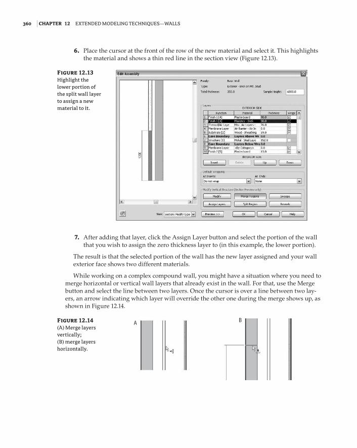
6. Place the cursor at the front of the row of the new material and select it. This highlights the material and shows a thin red line in the section view (Figure 12.13).
7. After adding that layer, click the Assign Layer button and select the portion of the wall that you wish to assign the zero thickness layer to (in this example, the lower portion).
The result is that the selected portion of the wall has the new layer assigned and your wall exterior face shows two different materials.
While working on a complex compound wall, you might have a situation where you need to merge horizontal or vertical wall layers that already exist in the wall. For that, use the Merge button and select the line between two layers. Once the cursor is over a line between two lay-ers, an arrow indicating which layer will override the other one during the merge shows up, as shown in Figure 12.14.
Figure 12.13 Highlight the lower portion of the split wall layer to assign a new material to it.
Figure 12.14 (A) Merge layers vertically; (B) merge layers horizontally.
A B
56491c12.indd 360 6/2/09 10:18:11 PM

using advancEd ModEling tEchniquEs for standard Walls | 361
Wall WrappingMaterials are detailed at insert conditions (where doors, windows, and openings are placed in walls) depending on the construction type, building conventions, and aesthetics. For this pur-pose, Revit provides Layer wrapping options in the wall Edit Assembly dialog box; however, they aren’t sufficient to accommodate a complex wrapping situation specific to a particular door or window. To achieve more control over these construction conditions, you need to set param-eters in the window or door family itself.
In the Family Editor, you can assign a Wall Closure property to reference planes. This param-eter defines a plane in the window family to which wall layers can wrap to.
In a door or window family, check the option Wall Closure in the Element Properties dialog box for the reference plane. This means that the exterior wall layers that have wraps assigned will terminate at this reference plane. The effect can be seen in Figure 12.15.
Sweeps and RevealsMany walls have linear embellishments that are attached or embedded in the construction. Cornices, brick soldier courses, and reveals are all examples. Using basic walls, you can add these elements directly into wall types.
Clicking the Sweeps or Reveals button in the Edit Assembly dialog box opens a new dialog box where you can define profile families to use as sweeps or reveals.
These are 2D shapes made out of simple lines and then swept along the length of the wall at a specified height. Many profiles representing cornices, skirting, and chair rails ship with Revit, but if you need to create a custom profile, you can use the Profile Family template. Open the Application Menu and choose New Family to access the Revit Family Editor templates. Choose a default Profile template. From here, you draw a single closed loop of lines at the desired real-world scale and load the profile back into your project. Be sure to use dimensions to verify the size of your profile. Follow these steps to get a feel for the workflow.
1. Click the wall tool from the Home tab, then click the Type Properties button in the Element Types dropdown menu, and then duplicate the type.
2. Open the Wall Assembly dialog box.
Figure 12.15 (A) The reference plane in the Family Editor, and (B) its effect when set to Wall Closure.
A B
56491c12.indd 361 6/2/09 10:18:11 PM

362 | Chapter 12 ExtEndEd ModEling tEchniquEs—Walls
3. In the preview view, switch to section view. The six Modify Vertical Structure options become active at the bottom of the dialog box.
4. Click the Sweeps button to bring up the Wall Sweeps dialog box, shown in Figure 12.16.
5. Click the Load Profile button, browse to the Profiles folder, and load these two profiles:
Cornice profile: Traditional (1)•u
Skirting profile: (Base 2, Ogee or similar)•u
6. Click the Add button. This adds a row in the dialog box that lets you select one of the loaded profiles and set its position relative to the wall geometry.
7. Add both profiles. Set the Traditional profile’s From value to Top and the Ogee profile’s From value to Base. Doing so attaches the profiles to the top and bottom of your wall. Figure 12.17 shows the profiles attached to the top and bottom of the wall.
8. Click OK. Draw a segment of this wall in the drawing area. Check out the wall in section and 3D views to see the result (see Figure 12.17).
Using the same principles outlined for adding traditional elements, you can get creative and add any type of profile you want. Figure 12.18 shows a wall with corrugated siding added as an integrated wall sweep.
Figure 12.16 The Wall Sweeps dialog box before inserting any profiles.
56491c12.indd 362 6/2/09 10:18:11 PM

using advancEd ModEling tEchniquEs for standard Walls | 363
Figure 12.17 Profiles attached to wall top and base.
Figure 12.18 Wall with cor-rugated siding created with inte-grated wall sweep.
56491c12.indd 363 6/2/09 10:18:11 PM

364 | Chapter 12 ExtEndEd ModEling tEchniquEs—Walls
rEvEals
Reveals can be added to a wall using the same workflow you use with sweeps; the only differ-ence is that the profile is subtractive rather than additive.
wall swEEp rETurns
When you’re working on traditional architectural projects, the wall sweeps usually wrap around door openings in thick walls. Revit can accommodate that using the Change Sweep Return com-mand. To understand this feature, follow this simple exercise:
1. Open a new session of Revit and place a generic wall. Switch to the default 3D view.
2. Rather than placing a sweep in the wall type (as we just did), you can use another method for placing sweeps: the Wall Sweep tool located in the Wall drop-down list.
These sweeps can be placed either vertically or horizontally using the contextual ribbon.
3. Add a horizontal sweep to the middle of the wall. Use the temporary dimensions to place the sweep at the desired height.
4. Choose the Wall Opening tool, located on the Modify tab.
56491c12.indd 364 6/2/09 10:18:12 PM

using advancEd ModEling tEchniquEs for standard Walls | 365
Select Wall Opening, and using this tool, draw an opening that intersects the sweep (Figure 12.19).
5. Select the sweep—it will display a blue grip at the end (the edge of the opening). Click the Modify Returns button in the Modify Sweeps contextual tab. Also take notice of the Options bar, where you can also set the angle of the return or decide to make a straight cut. The cursor turns into a knife symbol, and when you click somewhere on the profile it creates a new segment that can be wrapped around the edge of the opening. Press Esc or use the Modify tool to exit the command. You will need to zoom in close to the end of the sweep to really see the effect. (If you zoom very closely, the lines might become thick and ugly. In that case, click the Thin Lines Mode button on the View tab.)
6. Select the sweep again, and drag the control to adjust the length of the sweep. Figure 12.20 shows how the return can be modified.
Figure 12.19 A manually placed wall sweep inter-sected by a wall opening shown in (A) perspective and (B) elevation.
A B
Figure 12.20 Wall sweep returns.
56491c12.indd 365 6/2/09 10:18:12 PM

366 | Chapter 12 ExtEndEd ModEling tEchniquEs—Walls
ExTEnDing wall layErs BEyonD ThEir BasE
In many construction scenarios, you need layers of materials to extend beyond the base of the wall. A typical example is the extension of sheathing and siding on an exterior wall (Figure 12.21). Letting layers extend requires you to unlock the bottom edges of the wall from the sectional preview in the Edit Assembly dialog box. Once the layers have been unlocked, an instance parameter of the wall becomes enabled, either Base Extension Distance or Top Extension Distance (depending on which edges you unlocked). This value can be entered directly in the Element Properties dialog box or adjusted graphically when you select the wall by dragging the small blue triangle control at the bottom of the unlocked layer.
Follow these steps to enable the Base Extension parameter of a wall:
1. From the Home tab, create a new Wall. Select it and duplicate it by editing the type. Name it Exterior wood siding.
2. Select the structure parameter to open the Edit Assembly dialog box.
3. Add a new layer to the exterior of wall, set its function to Finish (4), use the material siding - clapboard, and give it 3⁄4² thickness.
4. Open the preview and look at the section view. Zoom into the bottom of the wall.
5. Select the Modify button located in the dialog box, and then click on the bottom edge of the exterior siding layer. Click the padlock icon to unlock the layer (Figure 12.22). Note that if you wanted to unlock additional layers, they all need to be adjacent—you cannot, for example, extend layers on either side of the core.
Figure 12.21 Example of wall layers extending past the base of the wall.
56491c12.indd 366 6/2/09 10:18:12 PM

using advancEd ModEling tEchniquEs for standard Walls | 367
6. The layer is now unlocked. Click OK twice to get back to the Instance Properties dialog box. You’ll see that the Base Extension Distance parameter is now enabled. Type in -10˝ for this parameter, and check the wall in 3D. You’ll see that the wood siding layer is now extending 10˝ below the level shown in Figure 12.23.
Figure 12.22 Use the padlock icon to unlock layers.
Figure 12.23 Modifying the wall layers to have a base extension.
56491c12.indd 367 6/2/09 10:18:13 PM
368 | Chapter 12 ExtEndEd ModEling tEchniquEs—Walls
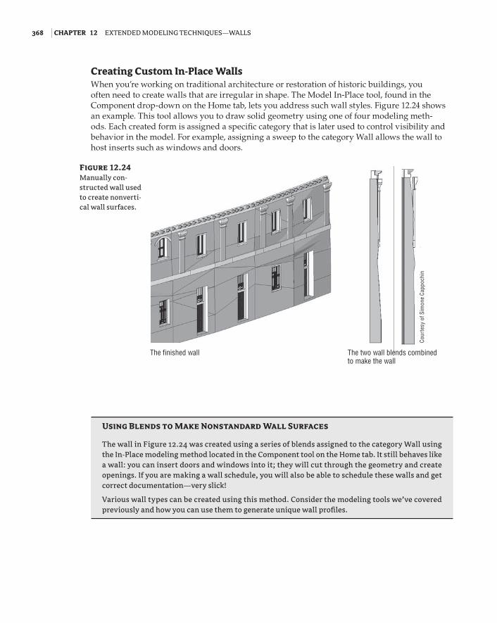
Creating Custom In-Place WallsWhen you’re working on traditional architecture or restoration of historic buildings, you often need to create walls that are irregular in shape. The Model In-Place tool, found in the Component drop-down on the Home tab, lets you address such wall styles. Figure 12.24 shows an example. This tool allows you to draw solid geometry using one of four modeling meth-ods. Each created form is assigned a specific category that is later used to control visibility and behavior in the model. For example, assigning a sweep to the category Wall allows the wall to host inserts such as windows and doors.
Using Blends to Make Nonstandard Wall Surfaces
The wall in Figure 12.24 was created using a series of blends assigned to the category Wall using the In-Place modeling method located in the Component tool on the Home tab. It still behaves like a wall: you can insert doors and windows into it; they will cut through the geometry and create openings. If you are making a wall schedule, you will also be able to schedule these walls and get correct documentation—very slick!
Various wall types can be created using this method. Consider the modeling tools we’ve covered previously and how you can use them to generate unique wall profiles.
Figure 12.24 Manually con-structed wall used to create nonverti-cal wall surfaces.
The finished wall The two wall blends combined to make the wall
Cour
tesy
of S
imon
e Ca
ppoc
hin
56491c12.indd 368 6/2/09 10:18:13 PM

using advancEd ModEling dEsign tEchniquEs for curtain Walls | 369
Using Advanced Modeling Design Techniques for Curtain WallsCurtain walls in Revit are unique wall types that allow you to embed divisions, mullions, and panels directly into the wall. They have a distinct set of properties, but still share many charac-teristics of basic walls.
The curtain wall A curtain wall is drawn like a basic wall and is available in the Type Selector when the Wall tool is active. It has top and bottom constraints, can be attached to roofs, can have its elevation profile sketch-edited, and is scheduled as a wall type.
Curtain grids These are used to lay out a grid that defines the physical divisions of the cur-tain wall. The layout grid can be designed freely as a combination of horizontal and vertical segments or can be a type with embedded rules that specify regular divisions. Figure 12.25 shows a typical grid division and expressive curtain panels in between.
Mullions These represent the metal profiles on a glass façade, and in Revit they follow the geometry of the grid. They can have any shape that is based on a mullion profile family. Mullions can be vertical or horizontal. If you have a playful spirit, however, you can make curved mullions as shown on Figure 12.26.
Figure 12.25 Curtain wall with regular orthogonal grids and expres-sive curtain panels.
Curtain grids
Mullions
Curtain panels
56491c12.indd 369 6/2/09 10:18:14 PM

370 | Chapter 12 ExtEndEd ModEling tEchniquEs—Walls
Curtain panels These fill in the space between gridlines and are always one of the following:
Empty panels No panel is placed between the grids.
Glazed panels These can be made out of different types of glass that can have any color or transparency.
Solid panels and panels with wall types These can take on any geometry you wish and thus create the most interesting structures, like the one shown in Figure 12.26.
Wall types as infill You can also choose from the Type Selector a wall type to fill the space between the gridlines (mullions). All wall types in the project will be available for your selection. Adding a wall type is usually a typical case in office partitions where the lower portion is a parapet wall and glass fills the upper portion of the metal stud wall.
Designing a Curtain WallIn this exercise, we’ll walk through the creation of a simple curtain wall. To draw a curtain wall, you can either draw a standard wall and then change its type to Curtain Wall or select a Curtain Wall type from the Wall Type Selector first. Follow these steps:
1. From the Home tab, select the Wall tool.
2. From the Type Selector, select Curtain Wall 1.
3. In the Level 1 plan view, draw a simple curtain wall (Figure 12.27). Use the wall type Curtain Wall 1.
Figure 12.26 With a little bit of inventive spirit, you can have curved mullions as well!
56491c12.indd 370 6/2/09 10:18:14 PM

using advancEd ModEling dEsign tEchniquEs for curtain Walls | 371
4. Toggle the view to see the result in 3D.
5. Divide the wall into panels using the Curtain Grid tool on the Home tab. Position your cursor over the edges of the wall to get a preview of where the grid will be placed. (Selecting a vertical edge places a horizontal grid, and selecting a horizontal edge allows a vertical grid.) Revit has some intelligent snapping built into grid placement that looks for midpoints and points that will divide the panel into thirds. Place the grid so that you get something like Figure 12.28.
Figure 12.27 A generic curtain wall before adding any grids or mul-lions looks like a simple glass wall.
Figure 12.28 Curtain wall with a few added grids.
56491c12.indd 371 6/2/09 10:18:14 PM

372 | Chapter 12 ExtEndEd ModEling tEchniquEs—Walls
6. Place mullions on the wall. You can place one mullion at a time by selecting separate grid segments. If you want to apply the same mullion on all segments, hold the Ctrl key and click a gridline to select all segments and apply the mullions. With mullions placed, your wall should look like Figure 12.29.
7. Let’s say you want to add more mullions, but this time you don’t want them to extend the entire height of the curtain wall. Select the Curtain Grid Line tool on the Home tab, and place new grids (Figure 12.30).
Figure 12.29 Mullions applied to the grids on a curtain wall.
Figure 12.30 To add more mul-lions, you will need to add another grid.
56491c12.indd 372 6/2/09 10:18:14 PM

using advancEd ModEling dEsign tEchniquEs for curtain Walls | 373
8. Before applying a mullion to the new gridline, delete the segments of the gridline where you don’t wish the mullion to occur. (You can also add grid segments that don’t span the entire panel. This may be faster than creating a long grid and then deleting the segments you don’t want.) Close the Curtain Grid tool, and select the newly created gridline. Click the Add or Remove Segments button in the contextual tab and click the segment you want removed.
Remove the top and bottom segments, and then add mullions (Figure 12.31).
Curtain PanelsCurtain panels fill the space between the curtain grids and mullions. These elements are cre-ated in the Family Editor using the Curtain Panels family template. Access them by choosing Application Menu New Family Curtain Wall Panel.rft. The Revit default template has a couple of curtain panels preloaded: System Panel Glazed and System Panel Solid. You can dupli-cate different types of these families and change the material, thickness, and offset to customize the appearance.
Figure 12.26, earlier in this chapter, shows some very creative curtain panels.
Figure 12.31 Removing portions of the grid and applying a mullion on the remaining segment of the grid.
56491c12.indd 373 6/2/09 10:18:14 PM

374 | Chapter 12 ExtEndEd ModEling tEchniquEs—Walls
sElEcTing ThE ElEmEnTs wiThin ThE curTain wall
Revit provides specially tailored selection options in the context menu to aid with workflow and interaction when you’re working with curtain walls.
When you hover the mouse over or select an element in a curtain wall, take note of the status bar in the lower-left corner of the screen: it tells you exactly the type of element you’re about to select or have already selected. Depending on what the mouse is hovering over, various selec-tion options are available. The elements you can select include the following:
The entire curtain wall entity (indicated by a green dashed line surrounding the •u
curtain wall)
A gridline•u
A mullion•u
A curtain panel•u
To select the element you want, use the Tab key until that element is highlighted.
Curtain Wall Doors and WindowsCurtain walls can host specially designed doors and windows. Keep in mind that standard doors and windows cannot be hosted by a curtain wall. These specially designed elements are recognizable in the library by a name that indicates they are curtain wall doors or win-dows. Revit schedules them as doors and windows, but their behavior is dependent on the curtain wall. Curtain wall doors and windows adapt their width and height to fill in grid cells. Essentially, they behave exactly like panels—they’ve just been made to appear and schedule as doors or windows. To insert a door within a curtain wall, choose Component Load from Library Load Family. Navigate to the Doors folder, and select a curtain wall door (single or double). Figure 12.32 shows a curtain door panel that has been swapped with a glazing panel. To make your own doors, select the Application Menu New Family Door - Curtain Wall.rft.
Figure 12.32 A special curtain wall door family is used to represent a door within a curtain wall.
56491c12.indd 374 6/2/09 10:18:14 PM

using advancEd ModEling dEsign tEchniquEs for curtain Walls | 375
Complex Curtain Wall PanelsLook at the complex-shaped curtain panels in Figure 12.33. You may think, “Oh, I can never do that!” Well, Revit can help you do it—and do it easily. The creation principle behind any of these types of curtain walls is the same as you learned in Chapter 10. By being smart about nesting and linking parameters, it is possible to build sophisticated curtain panel families.
Figure 12.33 Complex curtain wall panel example using a series of nested components.
56491c12.indd 375 6/2/09 10:18:15 PM

376 | Chapter 12 ExtEndEd ModEling tEchniquEs—Walls
The Bottom Line
Use advanced modeling techniques for standard walls. Many design situations require more than just the basic wall features; learn to use the more advanced Revit tools.
Master It A design calls for a horizontal soldier course in a brick wall every 12˝ on the façade. Using Revit, how would you build this into a wall element?
Use advanced modeling techniques to create stacked walls. Walls along a building façade usually have different construction layers from foundations to the top of the building. Stacked walls allow for a single wall to be constructed with varying wall types along its height.
Master It You have a building project where you are still experimenting with a number of floors but have already defined the wall types for the foundation, typical floor, and the attic and have combined them in a stacked wall type. How do you define the stacked wall so that it will accommodate middle floors with varying heights?
Use advanced modeling techniques for curtain walls. Curtain walls find their way into many architectural projects and designs. Knowing how to manipulate curtain walls in Revit is a key piece of the software for many design solutions.
Master It You’ve got to add a doorway to a storefront façade you’ve made. How would you go about doing this?
56491c12.indd 376 6/2/09 10:18:15 PM
Chapter 13
Extended Modeling Techniques—Roofs and Floors
In the previous chapters we covered basic modeling techniques for constructing a simple build-ing. We skipped over many additional features to give you a handle on essential workflow, the user interface, and making modifications to the model. In this chapter we cover more advanced features that are available any time you’re modeling in Revit. As you’ll see, with a little refinement and creativity, you can create a wide range of building components using the standard tools.
In this chapter, you’ll learn to:
Understand the various roof creation methods•u
Create all kinds of roofs•u
Work with advanced roof and floor shape editing•u
Understanding the Various Roof Creation MethodsIn real life, roofs can come in many shapes, sizes, and degrees of complexity. They can be as simple as a single-pitch shed roof, or they can involve complex sine curves or intersecting vaults. Once you understand Revit’s primary concepts, logic, and tools, you will be able to design just about any roof shape.
In general, roofs in Revit can be constructed in four different ways:
Roof by footprint Use this method to create any standard roof that more or less follows the shape of the building footprint and is a simple combination of roof pitches.
Roof by extrusion This method is best applied for roof shapes that are geometrically gener-ated by extrusion of a profile, such as sawtooth roofs, barrel vaults, and waveform roofs.
In-place roof This technique is used to accommodate roof shapes that cannot be achieved with either the footprint or extrusion methods. They are either done by using the general modeling techniques and applying a roof category to that geometry, or by using an under-lying mass form.
56491c13.indd 377 6/2/09 2:38:53 PM

378 | Chapter 13 ExtEndEd ModEling tEchniquEs—Roofs and flooRs
Roof by face In this technique, you select faces of massing forms to create standard thick-ness roofs. You can create those underlying massing forms within Revit, or import geometry created in other modeling applications into a mass family and use it as an underlay to create the roof by face. This technique is discussed in more detail in Chapter 8, “Concept Massing Study: Early Design Phase.”
The following sections provide a close look at these approaches and review their application to real-world scenarios.
Roof by FootprintUse the roof by footprint method to create any standard roof that more or less follows the shape of the footprint of the building and is a simple combination of roof pitches (Figure 13.1).
These roofs are based on a sketched shape that you define in plan view at the soffit level and that can be edited at any time during the development of a project from plan and axonometric 3D views. The shape can be drawn as a simple loop of lines using the Line tool, or can be created using the Pick Walls method, which also should result in a clean closed loop of lines. The latter means that the exterior walls are used to define the shape of the roof.
The best way to conceptualize the roof by footprint method is to understand that the sketched shape defining the main shape of the roof is just a simple, closed loop of lines—nothing more than that, regardless of whether it’s drawn or picked.
The Pick Walls method provides an intelligent selection method, so if you select walls as ref-erences to generate the sketch lines, with or without an offset to the walls, the lines will maintain a smart relationship with the walls. The Pick Walls method is the suggested approach for creating roofs by footprint. By selecting the walls to generate the sketch for the roof, you are creating an exclusive relationship between the walls and the roof so that if the design of your building later changes (wall position, level height, wall height, etc.), the roof will follow that change and adjust to the new wall position without any intervention from you (Figure 13.2). Like any change in Revit, this happens everywhere in all views, and thus not only the model but also its entire documentation and related quantities will be updated. This will not automatically occur if you just drew the roof lines and did not explicitly create a relationship between them and the under-lying walls.
Figure 13.1 Simple roof created using the roof by footprint method.
56491c13.indd 378 6/2/09 2:38:53 PM

undERstanding thE VaRious Roof cREation MEthods | 379
To guide you through the creation of roof by footprint and explain some of the main prin-ciples and tools, here is a brief exercise demonstrating the steps:
1. In a new project, open a Level 2 plan view and create a building footprint similar to Figure 13.3.
Figure 13.2 Examples of using the Pick method: (A) original roof; (B) entrance wall position has changed and roof has been updated automatically; (C) angle of wall to right of the entrance has changed and roof has changed to a new shape.
A
B
C
Figure 13.3 Draw a simple set of walls.
56491c13.indd 379 6/2/09 2:38:53 PM

380 | Chapter 13 ExtEndEd ModEling tEchniquEs—Roofs and flooRs
2. From the Build panel in the Home tab, select the Roof tool. The default setting for the Roof tool when you click on the Roof button is Roof by Footprint. The other roof creation options as well some other roof-related tools are available when you expand the Roof button using the little arrow in the icon.
3. From the Draw panel in the Create Roof Footprint tab, select the Pick Walls tool (this should be the default).
4. When you’ve chosen to create a roof by footprint, the Options bar makes the tools shown here available.
To define whether you want a sloped or flat roof, use the Defines Slope check box in the Options bar. The Overhang parameter allows you to define the value of the roof overhang beyond the wall. When the Extend into Wall (to Core) option is checked, the overhang is measured from the wall core. If the option is deselected, the overhang is measured from the exterior face of the wall.
5. After defining these settings, place your cursor over one of the walls (don’t click). Press the Tab key. This will result in both automatic selection of all walls and automatic indication of the roof overhang around those walls. Once you see the entire roof overhang indicated around all walls, click with the mouse over the wall. The dashed lines indicating the over-hang will turn into solid lines, confirming that the roof sketch is created. The lines will be offset from the walls by the value of the overhang that you defined in the Options bar. Your display should look like Figure 13.4.
6. Click the Finish Roof button at the top right of the ribbon menu.
If at any time the shape of the roof doesn’t meet your expectations, you can select the roof and select Edit Footprint from the Edit panel in the Modify Roofs tab to return to sketch mode, where you can edit lines or sketch lines or the slope.
Figure 13.4 Roof sketch lines are automatically drawn offset from the walls by the value of the over-hang as defined in the Options bar.
56491c13.indd 380 6/2/09 2:38:53 PM

undERstanding thE VaRious Roof cREation MEthods | 381
To change the slope definition or angle of individual portions of the roof, select the roof, and then from the Edit panel, click Edit Footprint. This brings you back to Sketch mode; select the sketch line of the roof portion for which you wish to change the slope and either toggle (check) the Defines Slope button in the Options bar to remove or add a slope, or click the slope value that is displayed when you select the sketch line to change the slope angle. If you mistakenly made all roof sides with slope but wanted to make a flat roof, you can Tab-select all sketch lines that form the roof shape and clear the Defines Slope box in the Options bar.
Roof slope can be measured in different ways: it can be set as an angle or percentage rise. You can find all slope measuring options on the Manage tab by selecting the Project Units in the Project Settings panel and then selecting Slope (see Figure 13.5). If the current slope value is not expressed in the units you want to use (such as percentage when you want it to display an angle), you’ll need to change the slope units in the Format dialog box. (You will not be able to do this while editing the roof slope.) Setting it here means specifying the way you measure slopes for the entire project.
Here are some of the important instance properties you should be aware of and know how to set properly. All are found in the dialog box shown in Figure 13.6:
Base Level As in other Revit elements, this is the level at which the roof is placed. The roof moves with this level if the level changes height.
Room Bounding When this is checked, the roof geometry has an effect on calculating room area and volume.
Related to Mass This property is active only if a roof has been created with the roof by face method (Conceptual Mass tools).
Base Offset from Level This option lowers or elevates the base of the roof relative to the base level.
Cutoff Level Many roof shapes require a combination of several roofs on top of each other. To do this, you need to cut off the top of a lower roof to accommodate the creation of the next roof in the sequence. Figure 13.7—in which the cutoff level is applied to the main roof and a secondary roof is built on top of the main roof using the cutoff level as a base—is an excellent example of this technique.
Figure 13.5 Format dialog box for slopes.
56491c13.indd 381 6/2/09 2:38:53 PM

382 | Chapter 13 ExtEndEd ModEling tEchniquEs—Roofs and flooRs
Cutoff Offset When the Cutoff tool is applied, the Cutoff Offset value also becomes active and allows you to set the cutoff distance from the level indicated in the Cutoff Level parameter.
Rafter Cut This defines the eave shape. You can select from Plumb Cut, Two Plumb Cut, or Two Plumb Square. When Two Plumb Square is selected, the Fascia Depth parameter is activated and you can set the value for the depth.
Rafter or Truss With Rafter, the offset of the base is measured from the inside of the wall. If you choose Truss, the plate offset from the base is measured from the outside of the wall. Figure 13.8 is a typical example of a roof by rafter cut.
Figure 13.6 Roof Properties dialog box.
Figure 13.7 The cutoff level is applied to the main roof, and a second-ary roof is built on top of the main roof using the cut-off level as a base.
56491c13.indd 382 6/2/09 2:38:54 PM

undERstanding thE VaRious Roof cREation MEthods | 383
Roof by ExtrusionThe roof by extrusion method is best applied to roof shapes that are generated by extrusion of a profile, such as sawtooth roofs, barrel vaults, and waveform roofs. Like the roof by footprint method, it is based on a sketch; however, the sketch that defines the shape of the roof is drawn in elevation or section view (not in plan view) and is then extruded along the plan of the build-ing (see Figure 13.9).
Figure 13.8 Construction drawing of a rafter detail.
Figure 13.9 A barrel-shaped roof extended with sunshades. The main roof is an extruded arch sketch.
56491c13.indd 383 6/2/09 2:38:54 PM

384 | Chapter 13 ExtEndEd ModEling tEchniquEs—Roofs and flooRs
The Roof by Extrusion tool offers additional settings in the Options bar when selected.
Roofs by extrusion do not have an option to follow the building footprint, but that is often needed to complete the design. To accommodate this, a special tool called Vertical Opening is provided. This tool is available when you select Roof by Extrusion from the Modify Roof panel on the Modify tab.
Here’s a brief explanation of how the tool works. First you create your roof by extrusion by defining a profile in elevation that is then extruded above the building. The extrusion follows a straight path, which probably is not the same as the building footprint (unless your building footprint is also a straight rectangle in shape). If the shape of the building is nonrectangular in footprint or the shape of the roof you want to create is not to be rectangular, this tool will let you carve geometry from the roof to match the footprint of the building or get any plan shape you need using a plan sketch.
You will recall that with sketch-based design, any closed loop of lines creates a positive shape, every next loop inside it is negative, the next one inside that negative one is positive, and so on. In Figure 13.10, a roof by extrusion was drawn at an angle to the underlying walls, but the final state should not extend beyond those walls. To clip the roof to meet the walls, the Vertical Opening tool was used to draw, in plan view of the roof, a negative shape that will remove the portions of the roof that extend beyond the walls.
Figure 13.10 The Vertical Opening tool applied in plan view to an extruded roof to follow the exterior shape of the building.
C. Resulting roof
A. Extrusion roof drawn at an angleB. 2 Vertical Opening sketch lines drawn: rectangular around the walls and a circular big one around it to cut off the unneeded roof.
56491c13.indd 384 6/2/09 2:38:54 PM

undERstanding thE VaRious Roof cREation MEthods | 385
Roof-in-PlaceThe roof-in-place technique accommodates roof shapes that cannot be achieved with either of the previously mentioned methods. It is the usual way to model historic roof shapes or challenging roof geometries such as domes and onion-domed roofs (see Figure 13.11).
Here’s the concept: you create a geometry using the Component tool found in the Home tab and select Model In-Place; then you can assign a roof category to it, and go wild with your creativity.
To start an in-place roof family, click the Component tool in Build panel of the Home tab. Select Roofs from the Family Category list (Figure 13.12), and click OK. This list allows Revit to assign a specific category (Roof in this case) to your in-place model and thus later schedule the new element as a roof.
You can create any roof shape using Solids and Voids and the modeling techniques of Extrusion, Blend, Revolve, Sweep, Swept Blend, or any combination of them (see Figure 13.13). There is a lot more information about some advanced shape-editing techniques later in this chapter, in the section “Working with Advanced Roofs and Floor Shape Editing.”
Figure 13.11 Manually constructed in-place roofs.
C. Traditional Russian onion dome (Revolve)
A. Barrel roof finishing with half dome (Extrusion + 1/2 Revolve)
B. Dome roof (Revolve only or Revolve + Extrusion)
56491c13.indd 385 6/2/09 2:38:55 PM
386 | Chapter 13 ExtEndEd ModEling tEchniquEs—Roofs and flooRs
Sloped GlazinG
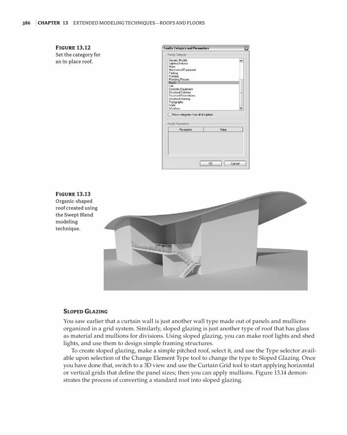
You saw earlier that a curtain wall is just another wall type made out of panels and mullions organized in a grid system. Similarly, sloped glazing is just another type of roof that has glass as material and mullions for divisions. Using sloped glazing, you can make roof lights and shed lights, and use them to design simple framing structures.
To create sloped glazing, make a simple pitched roof, select it, and use the Type selector avail-able upon selection of the Change Element Type tool to change the type to Sloped Glazing. Once you have done that, switch to a 3D view and use the Curtain Grid tool to start applying horizontal or vertical grids that define the panel sizes; then you can apply mullions. Figure 13.14 demon-strates the process of converting a standard roof into sloped glazing.
Figure 13.12 Set the category for an in-place roof.
Figure 13.13 Organic-shaped roof created using the Swept Blend modeling technique.
56491c13.indd 386 6/2/09 2:38:55 PM

undERstanding thE VaRious Roof cREation MEthods | 387
Figure 13.14 (A) Standard roof. (B) Convert a standard roof into sloped glazing. (C) Divide with curtain grid. (D) Add mullions to the grid. (E) Finish applying all mullions to the grid. (F) Change curtain panel from glass to empty. (G) Finished rafters.
A
B C
D E
F
G
56491c13.indd 387 6/2/09 2:38:56 PM
388 | Chapter 13 ExtEndEd ModEling tEchniquEs—Roofs and flooRs
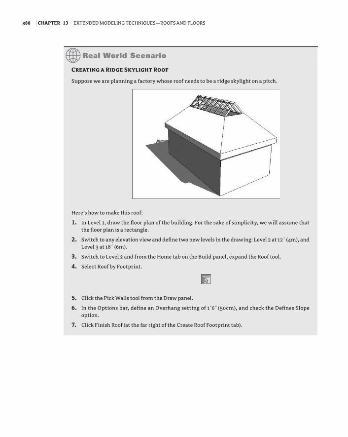
Creating a ridge Skylight roof
Suppose we are planning a factory whose roof needs to be a ridge skylight on a pitch.
Here’s how to make this roof:
1. In Level 1, draw the floor plan of the building. For the sake of simplicity, we will assume that the floor plan is a rectangle.
2. Switch to any elevation view and define two new levels in the drawing: Level 2 at 12́ (4m), and Level 3 at 18´ (6m).
3. Switch to Level 2 and from the Home tab on the Build panel, expand the Roof tool.
4. Select Roof by Footprint.
5. Click the Pick Walls tool from the Draw panel.
6. In the Options bar, define an Overhang setting of 1́ 6˝ (50cm), and check the Defines Slope option.
7. Click Finish Roof (at the far right of the Create Roof Footprint tab).
56491c13.indd 388 6/2/09 2:38:56 PM
undERstanding thE VaRious Roof cREation MEthods | 389
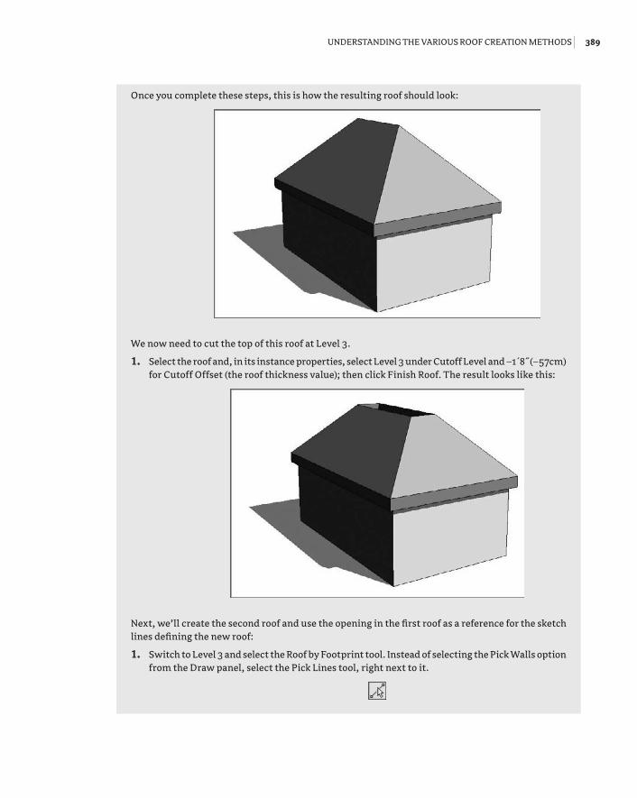
Once you complete these steps, this is how the resulting roof should look:
We now need to cut the top of this roof at Level 3.
1. Select the roof and, in its instance properties, select Level 3 under Cutoff Level and –1́ 8˝ (–57cm) for Cutoff Offset (the roof thickness value); then click Finish Roof. The result looks like this:
Next, we’ll create the second roof and use the opening in the first roof as a reference for the sketch lines defining the new roof:
1. Switch to Level 3 and select the Roof by Footprint tool. Instead of selecting the Pick Walls option from the Draw panel, select the Pick Lines tool, right next to it.
56491c13.indd 389 6/2/09 2:38:56 PM

390 | Chapter 13 ExtEndEd ModEling tEchniquEs—Roofs and flooRs
2. You will notice a Lock option in the Options bar. When checked, this option will lock the newly generated lines to the lines of the lower roof that you use as a reference. Check the Lock option.
3. Now select the four edges of the opening of the first roof: this results in the creation of four new rooflines for the upper roof that have a relationship with the lower roof sketch lines indicated by the four closed padlocks.
4. Click Finish Roof.
You just created the upper roof but also a relationship between the two roofs. That way, if you later change the cutoff level or the geometry, the second roof will change to match the new cutoff level.
5. Select the newly created roof, and select the Change Element Type tool to open the Type Selector. From there, pick Sloped Glazing to get the following configuration:
If the slope of the upper roof isn’t what you desire, you can change it at any time. Select the roof, click Edit Footprint in the Edit panel of the Modify Roofs tab, click each of the sketch lines, and type in a new value over the slope value displayed. In this example, we have set 9˝ for the upper roof (the skylight).
6. Divide the sloped glazing into segments and apply mullions. For that, use the Curtain Grid tool located in the Build panel of the Home tab and start dividing the glazing.
56491c13.indd 390 6/2/09 2:38:56 PM

undERstanding thE VaRious Roof cREation MEthods | 391
7. Add mullions by selecting the Mullion tool from the same Build panel and picking the gridlines on the glazing. The final outcome should be similar to this:
Sloped arrowS
Another way to slope a roof is by manually adding slope arrows to a sketch of flat roof slabs. This can be useful for unusual shapes, especially if the roof edges are not straight.
First create the sketch lines to define the shape of a roof, and do not check Defines Slope on the Options bar. Instead, choose the Slope Arrow tool from the Draw panel of the Modify tab. Draw the slope arrow in the direction you want your roof to pitch and at the intended height between the base of the roof and sloped end (see Figure 13.15).
Once you’ve drawn the slope arrow, you can select it, and click on the Properties button in the Draw panel to open the Instance properties dialog box and set any of the parameters shown in Figure 13.16. The most critical parameter to check is Height Offset at Head. This defines the height of the roof slab from the base to the top of its slope.
Figure 13.15 A slope-defining arrow is added to the sketch in Roof by Footprint.
56491c13.indd 391 6/2/09 2:38:56 PM

392 | Chapter 13 ExtEndEd ModEling tEchniquEs—Roofs and flooRs
To create a shed roof, you can draw a roof without any slope-defining sides and then apply a slope arrow that defines the exact sloping (see Figures 13.17 and 13.18).
Figure 13.16 Slope arrow properties.
Figure 13.17 A shed roof defined using the Slope Arrow tool.
Figure 13.18 The same roof, with the slope arrow shortened. Note that the roof became much steeper.
56491c13.indd 392 6/2/09 2:38:57 PM

cREating all Kinds of Roofs | 393
Creating All Kinds of RoofsThe following section demonstrates a series of typical roof conditions and the appropriate strat-egy to use in Revit to create these roofs. For any roof, there can be many ways to solve it geo-metrically. You can use this section as a guide and to shore up your skills with the roof tools and methods described previously in this chapter.
Each roof in the typology is represented with the roof plan view, sketch plan, and 3D view of the roof.
Flat RoofWe created this flat roof using Roof by Footprint and the Pick Walls tool; we also unchecked Defines Slope on the Options bar.
56491c13.indd 393 6/2/09 2:38:57 PM

394 | Chapter 13 ExtEndEd ModEling tEchniquEs—Roofs and flooRs
Gable Roof with Asymmetric SlopesWe also created this roof using Roof by Footprint and the Pick Walls tool. But in this example we checked Defines Slope for the shorter sides of the roof, and the slope angles are not identical.
56491c13.indd 394 6/2/09 2:38:57 PM

cREating all Kinds of Roofs | 395
Shed RoofWe created this Roof by Footprint by using the Pick Walls tool and checked Defines Slope for only one of the short sides of the roof.
56491c13.indd 395 6/2/09 2:38:57 PM

396 | Chapter 13 ExtEndEd ModEling tEchniquEs—Roofs and flooRs
Note that you could also make this same roof by adding a Slope arrow to a flat roof:
Hipped RoofWe created this Roof by Footprint by using the Pick Walls tool, and Defines Slope was checked for all sides of the roof.
56491c13.indd 396 6/2/09 2:38:58 PM

cREating all Kinds of Roofs | 397
Hip Roof Following Recessed WallsWe created this Roof by Footprint by using the Pick Walls tool. Defines Slope was checked for all sides of the roof except the three walls that recess toward the inside.
56491c13.indd 397 6/2/09 2:38:58 PM

398 | Chapter 13 ExtEndEd ModEling tEchniquEs—Roofs and flooRs
Gable RoofWe created this Roof by Footprint by using the Pick Walls tool and checking Defines Slope for all sides of the roof but not for the one that recesses toward the interior of the building.
56491c13.indd 398 6/2/09 2:38:58 PM

cREating all Kinds of Roofs | 399
Gable Roof with Extending PergolaThis Roof by Footprint was created over a rectangular floor plan using the Pick Walls tool. We then edited its sketch and included additional sketch lines to shape the extension. We checked Defines Slope only for the sides indicated in the sketch.
56491c13.indd 399 6/2/09 2:38:58 PM

400 | Chapter 13 ExtEndEd ModEling tEchniquEs—Roofs and flooRs
Hip and Gable Hybrid RoofWe created this Roof by Footprint by using the Pick Walls tool with Defines Slope checked for all sides.
Notice that we split the sketch lines of the shorter sides in thirds and checked Defines Slope only for the middle portion of the line, as shown here
56491c13.indd 400 6/2/09 2:38:59 PM

cREating all Kinds of Roofs | 401
Gambrel RoofWe created this Roof by Footprint by using the Pick Walls tool. We checked Defines Slope for the two long sides of the roof only. We cut the roof off at a certain height (cutoff level), and created a second roof using as a sketch the cutoff shape of the first roof. For the second roof, we checked the Defines Slope option for its two longer sides.
56491c13.indd 401 6/2/09 2:38:59 PM

402 | Chapter 13 ExtEndEd ModEling tEchniquEs—Roofs and flooRs
Dutch Gable with Glazed RoofWe created this Roof by Footprint by using the Pick Walls tool and checking Defines Slope for all sides of the roof. We cut the roof off at a certain height (cutoff level), and created a second roof using as a sketch the cutoff shape of the first roof. We set the Type value of the second roof to Sloped Glazing. For the second roof we also checked Defines Slope for all sides of the roof, but the slope of the second roof is slightly steeper than that of the first roof. We applied curtain grid and mullions to the sloped glazing. (See “Real World Scenario: Creating a Ridge Skylight Roof” earlier in this chapter for a full step-by-step procedure for this example.)
56491c13.indd 402 6/2/09 2:38:59 PM

cREating all Kinds of Roofs | 403
Dutch GableWe created this Roof by Footprint by using the Pick Walls tool and checking Defines Slope for all sides of the roof. We cut the roof off at a certain height (cutoff level), and we created a second roof using as a sketch the cutoff shape of the first roof. We checked Defines Slope for all sides of the second roof; the slope of the second roof is slightly steeper than the slope of the first roof.
56491c13.indd 403 6/2/09 2:39:00 PM

404 | Chapter 13 ExtEndEd ModEling tEchniquEs—Roofs and flooRs
Hipped Roof with Sloped Arrow DormerWe created this Roof by Footprint by using the Pick Walls tool and checking Defines Slope for all sides of the roof. We split the sketch line on the south of the building into four segments to allow for the dormer creation. We added sloped arrows facing each other and meeting in one point to the middle two segments of the split sketch line.
56491c13.indd 404 6/2/09 2:39:00 PM

cREating all Kinds of Roofs | 405
Hipped Roof with Two DormersWe created this Roof by Footprint by using the Pick Walls tool and checking Defines Slope for all sides of the roof. The two dormers are also separate roofs created by the footprint of the walls defining the sides of the dormer. We then joined the roofs. The opening in the roof slab is made up of two simple closed loops of lines (this can be done directly in Sketch mode or later, using the Openings tool from the Modify tab).
56491c13.indd 405 6/2/09 2:39:00 PM

406 | Chapter 13 ExtEndEd ModEling tEchniquEs—Roofs and flooRs
Four-Sided GableWe created this Roof by Footprint by using the Line tool from the Draw panel in the shape indi-cated in the sketch. Defines Slope is checked for all four corners (see the blowups of the corner and middle roof edge).
56491c13.indd 406 6/2/09 2:39:00 PM

cREating all Kinds of Roofs | 407
Hipped Roof with Extruded Roof DormerWe created this Roof by Footprint by using the Pick Walls tool with Defines Slope checked for all sides of the roof. We created the dormer roof as a roof by extrusion by using the wall face as a work plane, and then joined with the other roof in the sketch (you could also use the Openings tool later).
56491c13.indd 407 6/2/09 2:39:01 PM
408 | Chapter 13 ExtEndEd ModEling tEchniquEs—Roofs and flooRs
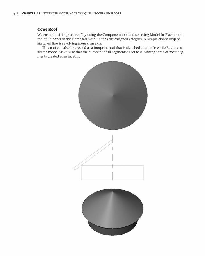
Cone RoofWe created this in-place roof by using the Component tool and selecting Model In-Place from the Build panel of the Home tab, with Roof as the assigned category. A simple closed loop of sketched line is revolving around an axis.
This roof can also be created as a footprint roof that is sketched as a circle while Revit is in sketch mode. Make sure that the number of full segments is set to 0. Adding three or more seg-ments created even faceting.
56491c13.indd 408 6/2/09 2:39:01 PM
cREating all Kinds of Roofs | 409
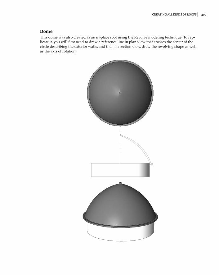
DomeThis dome was also created as an in-place roof using the Revolve modeling technique. To rep-licate it, you will first need to draw a reference line in plan view that crosses the center of the circle describing the exterior walls, and then, in section view, draw the revolving shape as well as the axis of rotation.
56491c13.indd 409 6/2/09 2:39:01 PM

410 | Chapter 13 ExtEndEd ModEling tEchniquEs—Roofs and flooRs
Barrel RoofWe created this example with the Roof by Extrusion method. A simple line in arc shape defines the main shape of the roof extruded over the building footprint. In this example we included an additional roof by extrusion and converted it into sloped glazing. The edges of the roof have been rounded using the Vertical Opening tool. The sloped glazing curtain panel type is set to Empty Glazing, which allows the mullion structure to create a sunshade.
56491c13.indd 410 6/2/09 2:39:01 PM
cREating all Kinds of Roofs | 411
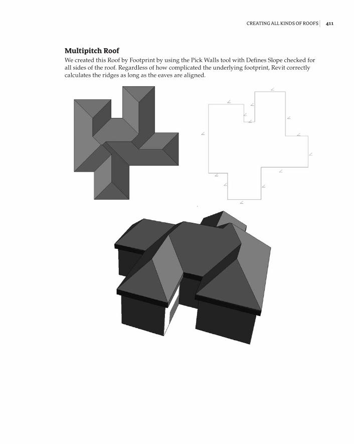
Multipitch RoofWe created this Roof by Footprint by using the Pick Walls tool with Defines Slope checked for all sides of the roof. Regardless of how complicated the underlying footprint, Revit correctly calculates the ridges as long as the eaves are aligned.
56491c13.indd 411 6/2/09 2:39:02 PM

412 | Chapter 13 ExtEndEd ModEling tEchniquEs—Roofs and flooRs
Creating a Dormer
Roofs with dormers generally cause grief for architects, so we’ll guide you through the creation of one.
1. Create the base of a building, set up three levels, and create a Roof by Footprint with Defines Slope checked for all sides.
2. Approximately in the position indicated in the following graphic, on Level 2 create the four walls of a dormer using the Wall tool. Set their height to such a value that they extend above the roof. (For easier verification, create a cross section through the dormer to check the height of the dormer walls, and if necessary, modify their height in the element properties so that they extend above the roof.)
3. Using the Roof by Footprint tool, create a pitched roof on top of the dormer walls.
4. If you switch to a side elevation view, you will notice that the dormer roof probably does not extend to meet the main roof. Therefore, you will need to use the Join/Unjoin Roof tool, located on the Modify tab in the Edit Geometry panel, to join the main roof and the dormer. Select the Join/Unjoin Roof tool, select the main roof as the target, and then select the edge of the dormer roof to extend.
56491c13.indd 412 6/2/09 2:39:02 PM

cREating all Kinds of Roofs | 413
5. From the Edit Geometry panel on the Modify tab, expand the Openings tools and select Dormer Opening. Now pick first the main roof, then the dormer roof, and then the sides of the walls that define the dormer. Select the inside faces of the walls. Unlike with most sketches, in this case you will not need to provide a closed loop of lines. Finish the dormer opening.
6. Go back to the section view you previously created and edit the elevation profile of the walls to make sure they don’t extend below or above the roofs. Note that you should not use the Top/Base Attach tool; instead use the Edit Profile tool available in the Edit panel on the Modify Walls tab to edit its elevation profile. Then manually change the base sketch line of the walls to get the triangular elevation profile as shown here:
56491c13.indd 413 6/2/09 2:39:02 PM

414 | Chapter 13 ExtEndEd ModEling tEchniquEs—Roofs and flooRs
Your dormer opening is now correct and you will see that it has cut the roof in two directions, as a true dormer needs to.
56491c13.indd 414 6/2/09 2:39:02 PM

cREating all Kinds of Roofs | 415
As a final touch, you can convert the front wall of the dormer to a storefront wall type or add a window.
56491c13.indd 415 6/2/09 2:39:03 PM

416 | Chapter 13 ExtEndEd ModEling tEchniquEs—Roofs and flooRs
Working with Advanced Roof and Floor Shape EditingNo flat roof is ever really flat! And Revit is equipped with smart tools that allow for tapered insulation over a flat roof and similar conditions. A rich set of shape editing tools for roofs and floors help create and modify such conditions in no time. These powerful tools are modifiers that are applicable to roofs and floors and will allow you to model concrete slabs with multiple slopes, often referred to as warped slabs (see Figure 13.19).
The set of tools available for editing floor and roof shapes are called Modification tools and appear in the Shape Editing panel of the Modify tab when a roof is selected. Here is what each tool is meant to do (left to right):
Modify Sub Elements This tool allows you to direct edit element geometry using selection and modification of points (vertices) and edges.
Add Point This tool allows you to add points on the top face of a roof or floor. Points can be added on edges or surfaces.
Add Split Line This tool allows you to sketch directly on the top face of the element, which adds split lines to the floor and roof so that hips and valleys can be created.
Pick Supports This tool allows you to pick linear beams and walls to create new split edges at the correct elevation automatically.
As you will see, once any of these modifiers are applied to a floor or roof, a new Reset Shape button appears on the tab when the roof is selected. Select this button to remove all modifiers applied to the floor or roof that you have selected.
Figure 13.19 Sloped roof with drainage.
56491c13.indd 416 6/2/09 2:39:03 PM

WoRKing With adVancEd Roof and flooR shapE Editing | 417
Sloped RoofsLet’s do a short exercise that shows how to make a sloped roof like the one in Figure 13.20 (shown in plan view).
Follow these steps:
1. Open Modifying Roof Shape start.rvt from the book’s companion web page (www.sybex.com/go/masteringrevit2010).
2. Select the roof that has already been prepared for you.
3. From the Shape Editing panel, activate the Add Split Line tool (note that the color of the rest of the model grays out while the roof lines are dashed green).
4. Draw ridge lines to divide the roof into areas that will be independently drained. The ridge lines will be drawn in blue color.
5. Using the same tool, draw diagonal lines within those areas to create the valleys. Make sure you zoom in closely when drawing the diagonal lines, so to be sure that you are snapping in the exact same diving points. (Should you notice that you have not snapped well, select the Modify Sub Elements tool, delete the incorrect segments, and try again.)
You have split the roof surfaces into many subfloors, but they are still all at the same height and inclination. You should have a roof that looks like Figure 13.21. Take care when sloping structures using this method; the structural thickness decreases with changes in slope. Press Esc to exit editing mode.
Figure 13.20 A roof plan show-ing a roof divided into segments, with drainage points.
Figure 13.21 Using the Add Split Line tool, you can create ridges and valleys.
56491c13.indd 417 6/2/09 2:39:03 PM
418 | Chapter 13 ExtEndEd ModEling tEchniquEs—Roofs and flooRs
6. Switch to a 3D view.
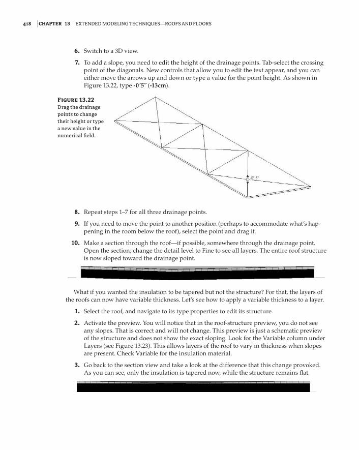
7. To add a slope, you need to edit the height of the drainage points. Tab-select the crossing point of the diagonals. New controls that allow you to edit the text appear, and you can either move the arrows up and down or type a value for the point height. As shown in Figure 13.22, type -0´5˝ (-13cm).
8. Repeat steps 1–7 for all three drainage points.
9. If you need to move the point to another position (perhaps to accommodate what’s hap-pening in the room below the roof), select the point and drag it.
10. Make a section through the roof—if possible, somewhere through the drainage point. Open the section; change the detail level to Fine to see all layers. The entire roof structure is now sloped toward the drainage point.
What if you wanted the insulation to be tapered but not the structure? For that, the layers of the roofs can now have variable thickness. Let’s see how to apply a variable thickness to a layer.
1. Select the roof, and navigate to its type properties to edit its structure.
2. Activate the preview. You will notice that in the roof-structure preview, you do not see any slopes. That is correct and will not change. This preview is just a schematic preview of the structure and does not show the exact sloping. Look for the Variable column under Layers (see Figure 13.23). This allows layers of the roof to vary in thickness when slopes are present. Check Variable for the insulation material.
3. Go back to the section view and take a look at the difference that this change provoked. As you can see, only the insulation is tapered now, while the structure remains flat.
Figure 13.22 Drag the drainage points to change their height or type a new value in the numerical field.
56491c13.indd 418 6/2/09 2:39:03 PM

WoRKing With adVancEd Roof and flooR shapE Editing | 419
Warped SurfacesWarped surfaces can also be created using this tool. Using the Roof by Footprint method, draw a flat roof, uncheck Defines Slopes, and then select the roof. Using the Modify Sub Elements tool, you can start moving edge points up and down (Figure 13.24).
Figure 13.23 The Edit Roof Structure dialog box.
Figure 13.24 Warped roof.
56491c13.indd 419 6/2/09 2:39:03 PM

420 | Chapter 13 ExtEndEd ModEling tEchniquEs—Roofs and flooRs
The Bottom Line
Understand the various roof creation methods. There are multiple methods for creating roof forms in Revit, and you should become familiar with each.
Master it When would you use a Roof by Extrusion method?
Create all kinds of roofs. Roofs are an integral part of any building. Knowing how to cre-ate them in a variety of shapes and sizes is critical to the success of a project.
Master It In the early design phases of a project, you are exploring a variety of roof forms for your building. Create the base building form and explore different roof options and shapes. How would you go about exploring a variety of roof shapes?
Work with advanced roof and floor shape editing. Roofs are another seemingly simple element that presents architectural challenges, and Revit has tools for them.
Master It You are working on a flat roof retail project, but the roof is not really flat and will need to drain. Using Revit roof tools, how would you go about modeling this?
56491c13.indd 420 6/2/09 2:39:03 PM