express5800/b120e-h user's guide - nec(japan) · 2013-08-28 · 2 express5800/b120e-h...
TRANSCRIPT
NEC Express Server Express5800 Series
Express5800/B120e-h User’s Guide
Chapter 1 General Description
Chapter 2 Preparations
Chapter 3 Setup Chapter 4 Appendix
40.101.01-101.01July 2013, First Edition
© NEC Corporation 2013
Model Number: N8400-215F/216F/217F/218F/219F/220F

Documents Provided with This Product
Express5800/B120e-h User's Guide 2
Documents Provided with This Product
Documents for this product are provided as accompanying booklets ( ) and as electronic manuals ( PDF ) stored within the EXPRESSBUILDER DVD ( ).
Precautions for Use Describes points of caution to ensure the safe use of this server. Read these cautions before using this server.
Getting Started Describes how to use this server, from unpacking to operations. Refer to this guide as you begin for an overview of this server.
User’s Guide Chapter 1: General Description Overviews, names, and functions of the server’s parts
Chapter 2: Preparations Installation of additional options, connection of peripheral devices, and ideal location for this server
Chapter 3: Setting Up Your Server System BIOS configurations and summary of EXPRESSBUILDER
Chapter 4: Appendix Specifications and other information
Installation Guide (Windows) Chapter 1: Installing Windows Installation of Windows and drivers, and important information for
installation
Chapter 2: Installing the Bundled Software
Installation of bundled software, such as NEC ESMPRO and Universal RAID Utility
Maintenance Guide
Chapter 1: Maintenance Server maintenance and troubleshooting
Chapter 2: Convenient Features Useful features and the detail of system BIOS settings, RAID Configuration Utility, and EXPRESSBUILDER
Chapter 3: Appendix Error messages and Windows Event Logs
Other documents PDF
Provides the detail of NEC ESMPRO, Universal RAID Utility, and the other features.
EXPRESSBUILDER

Contents
Express5800/B120e-h User's Guide 3
Contents
Documents Provided with This Product.................................................................................................................2
Contents................................................................................................................................................................3
Notations Used in This Document .........................................................................................................................6 Notations used in the text....................................................................................................................6 Optical disk drives...............................................................................................................................6 Hard Disk Drives .................................................................................................................................6 Removable media ...............................................................................................................................6 Abbreviations of Operating Systems (Windows) .................................................................................7
Trademarks ...........................................................................................................................................................8
Regulatory Notices................................................................................................................................................9
Warnings and Additions to This Document..........................................................................................................12 Latest editions...................................................................................................................................12
Precautions for Use (Be Sure to Read) ...................................................................................................13 Safety precautions ............................................................................................................................13 Symbols used in this document and on warning labels.....................................................................14 Safety notes ......................................................................................................................................15 Handling precautions (for proper operations)....................................................................................17 Handling precautions (for Anti-static Measures)................................................................................19 Handling precautions (Power-saving feature) ...................................................................................20
Chapter 1 General Description ........................................................................................................................22
1. Introduction.....................................................................................................................................................23
2. Accessories ....................................................................................................................................................24
3. Standard Features ..........................................................................................................................................25 3.1 Overview of Blade Server ..........................................................................................................27 3.2 Management Features...............................................................................................................28 3.3 About the Monitoring of Chassis Sensors ..................................................................................29 3.4 Firmware and Software Version Management ...........................................................................29
4. Names and Features of Component...............................................................................................................30 4.1 CPU Blade .................................................................................................................................30 4.2 Solid State Drive (SSD)..............................................................................................................34 4.3 Lamp Indications........................................................................................................................35
4.3.1 POWER Lamp........................................................................................................35 4.3.2 STATUS Lamp........................................................................................................36 4.3.3 LAN (1 - 2) Link/Access Lamps ..............................................................................37 4.3.4 ID Lamp..................................................................................................................37 4.3.5 SSD Access Lamp..................................................................................................37
Chapter 2 Preparations....................................................................................................................................38
1. Installing Internal Optional Devices ................................................................................................................39 1.1 Safety Precautions.....................................................................................................................39 1.2 Overview of Installation and Removal........................................................................................40 1.3 Installation and Removal Procedure (Common section) ............................................................41
1.3.1 Removal of top cover..............................................................................................41 1.3.2 Removal of air duct.................................................................................................42 1.3.3 Installation of top cover and air duct .......................................................................44

Contents
Express5800/B120e-h User's Guide 4
1.4 Processor (CPU)........................................................................................................................45 1.4.1 Installation ..............................................................................................................46 1.4.2 Removal .................................................................................................................50
1.5 DIMM .........................................................................................................................................51 1.5.1 Adding Order and Precautions................................................................................52 1.5.2 Installation ..............................................................................................................52 1.5.3 Removal .................................................................................................................53
1.6 Mezzanine Card.........................................................................................................................54 1.6.1 Notes ......................................................................................................................55 1.6.2 Installation ..............................................................................................................55 1.6.3 Removal .................................................................................................................57
1.7 Solid State Drive (SSD)..............................................................................................................58 1.7.1 Installation ..............................................................................................................59 1.7.2 Removal .................................................................................................................62 1.7.3 Replacement ..........................................................................................................63 1.7.4 Resetting Management Information........................................................................66
1.8 Use of Internal Hard Disk Drives in the RAID System ...............................................................67 1.8.1 Enabling a RAID System ........................................................................................67 1.8.2 Notes on setting up a RAID System .......................................................................68
1.9 Trusted Platform Module Kit.......................................................................................................69 1.9.1 Installation ..............................................................................................................70 1.9.2 Removal .................................................................................................................71
1.10 Internal Flash Memory.............................................................................................................72 1.10.1 Notes ....................................................................................................................73 1.10.2 Installation.............................................................................................................73 1.10.3 Removal................................................................................................................74
2. Installation and Connection ............................................................................................................................75 2.1 Installation..................................................................................................................................75
2.1.1 Checking MAC Address..........................................................................................76 2.2 Connecting Peripheral Devices..................................................................................................78
2.2.1 USB Connection by K410-150(00) SUV Cable.......................................................81 2.2.2 Connecting with Network........................................................................................81 2.2.3 Connecting with UPS..............................................................................................82
Chapter 3 Setup...............................................................................................................................................83
1. Power-on of Blade Server ..............................................................................................................................84 1.1 Power ON from CPU Blade .......................................................................................................85 1.2 Power ON from Network Serial Port ..........................................................................................86 1.3 Power ON from Remote Console ..............................................................................................86 1.4 Operation after Power ON .........................................................................................................86 1.5 POST.........................................................................................................................................87
1.5.1 POST Execution Flow ............................................................................................87 1.5.2 POST Error Messages ...........................................................................................89
2. BIOS Setup Utility (SETUP) ...........................................................................................................................90 2.1 Overview....................................................................................................................................90 2.2 Starting and Exiting SETUP Utility .............................................................................................90 2.3 Description on On-Screen Items and Key Usage ......................................................................91 2.4 Cases that Require Configuration..............................................................................................93
3. EXPRESSSCOPE ENGINE 3 ........................................................................................................................95 3.1 Overview....................................................................................................................................95 3.2 EXPRESSSCOPE ENGINE 3 Network Configuration ...............................................................96
4. EXPRESSBUILDER.......................................................................................................................................98 4.1 Features of EXPRESSBUILDER ...............................................................................................98 4.2 Starting EXPRESSBUILDER .....................................................................................................98
5. Installing Software Components .....................................................................................................................99 5.1 Notes on using Red Hat Enterprise Linux 6 ...............................................................................99
5.1.1 About the message caused by power consumption control in Red Hat Enterprise Linux 6.....................................................................................99

Contents
Express5800/B120e-h User's Guide 5
6. Device Identification ..................................................................................................................................... 101
7. Power-off of Blade Server............................................................................................................................. 102
Chapter 4 Appendix ....................................................................................................................................... 103
1. Specifications ............................................................................................................................................... 104
2. Interrupt Lines............................................................................................................................................... 107

Notations Used in This Document
Express5800/B120e-h User's Guide 6
Notations Used in This Document
Notations used in the text
In addition to safety-related symbols urging caution, 3 other types of notations are used in this document. These notations have the following meanings.
Important Indicates critical items that must be followed when handling the server or operating software. If the procedures described are not followed, server failure, data loss, and other serious malfunctions could occur.
Note Indicates items that must be confirmed when handling the server or operating software.
Tips Indicates information that is helpful to keep in mind when using this server.
Optical disk drives
This server is equipped with one of the following drives, depending on the order at the time of purchase. These drives are referred to as optical disk drives in this document.
● DVD-ROM drive
● DVD Super MULTI drive
Hard Disk Drives
Unless otherwise stated, Hard Disk Drives (HDD) described in this document refer to the following.
● Hard disk drives (HDD)
● Solid state drive (SSD)
Removable media
Unless otherwise stated, removable media described in this document refer to the following.
● USB memory
● Flash FDD

Notations Used in This Document
Express5800/B120e-h User's Guide 7
Abbreviations of Operating Systems (Windows)
Windows Operating Systems are referred to as follows.
Refer to Chapter 1 (1.2 Supported Windows OS) in Installation Guide (Windows) for detailed information.
Notations in this document Official names of Windows
Widnows Server 2012 Standard Windows Server 2012
Widnows Server 2012 Datacenter
Windows Server 2008 R2 Standard Windows Server 2008 R2
Windows Server 2008 R2 Enterprise
Windows Server 2008 Standard Windows Server 2008 *
Windows Server 2008 Enterprise
* Includes 64-bit and 32-bit Editions unless otherwise stated. The following appears on EXPRESSBUILDER.
• Windows Server 2008 64-bit Edition: Windows Server 2008 x64 • Windows Server 2008 32-bit Edition: Windows Server 2008 x86

Trademarks
Express5800/B120e-h User's Guide 8
Trademarks
EXPRESSSCOPE is a registered trademark of NEC Corporation.
Microsoft, Windows, Windows Server, and MS-DOS are registered trademarks or trademarks of Microsoft Corporation in the United
States and other countries. Intel, Pentium, and Xeon are registered trademarks of Intel Corporation of the United States.
AT is a registered trademark of International Business Machines Corporation of the United States and other countries.
Adaptec, its logo, and SCSISelect are registered trademarks or trademarks of Adaptec, Inc. of the United States.
LSI and the LSI logo design are trademarks or registered trademarks of LSI Corporation.
Adobe, the Adobe logo, and Acrobat are trademarks of Adobe Systems Incorporated.
DLT and DLTtape are trademarks of Quantum Corporation of the United States.
PCI Express is a trademark of Peripheral Component Interconnect Special Interest Group. Linux is a trademark or registered trademark of Linus Torvalds in Japan and other countries.
Red Hat® and Red Hat Enterprise Linux are trademarks or registered trademarks of Red Hat, Inc. in the United States
and other countries.
All other product, brand, or trade names used in this publication are the trademarks or registered trademarks of their respective
trademark owners.

Regulatory Notices
Express5800/B120e-h User's Guide 9
Regulatory Notices
FCC Statement This equipment has been tested and found to comply with the limits for a Class A digital device, pursuant to Part 15 of the FCC Rules. These limits are designed to provide reasonable protection against harmful interference when the equipment is operated in a commercial environment. This equipment generates, uses, and can radiate radio frequency energy and, if not installed and used in accordance with the instruction manual, may cause harmful interference to radio communications. Operation of this equipment in a residential area is likely to cause harmful interference in which case the user will be required to correct the interference at his own expense. Industry Canada Class A Emission Compliance Statement This Class A digital apparatus complies with Canadian ICES-003. Avis de conformité à la réglementation d'Industrie Canada Cet appareil numérique de la classe A est conforme à la norme NMB-003 du Canada. CE Statement This is a Class A product. In domestic environment this product may cause radio interference in which case the user may be required to take adequate measures (EN55022). BSMI Statement
WEEE
Disposing of your used product
In the European Union EU-wide legislation as implemented in each Member State requires that used electrical and electronic products carrying the mark (left) must be disposed of separately from normal household waste. This includes Information and Communication Technology (ICT) equipment or electrical accessories, such as cables or DVDs. When disposing of used products, you should comply with applicable legislation or agreements you may have. The mark on the electrical and electronic products only applies to the current European Union Member States.
Outside the European Union If you wish to dispose of used electrical and electronic products outside the European Union, please contact your local authority and ask for the correct method of disposal.

Regulatory Notices
Express5800/B120e-h User's Guide 10
Vietnam RoHS information relevant for Vietnam market
Declaration of Conformity with the requirements of Technical Regulation on the Restriction Of the use of certain Hazardous
Substances in Electrical and Electronic Equipment (adopted by Order №1057 of Cabinet of Ministers of Ukraine)
The Product is in conformity with the requirements of Technical Regulation on the Restriction Of the use of certain Hazardous Substances in electrical and electronic equipment (TR on RoHS). The content of hazardous substance with the exemption of the applications listed in the Annex №2 of TR on RoHS:
1. Lead (Pb) – not over 0,1wt % or 1000wt ppm; 2. Cadmium (Cd) – not over 0,01wt % or 100wt ppm; 3. Mercury (Hg) – not over 0,1wt % or 1000wt ppm; 4. Hexavalent chromium (Cr6+) – not over 0,1wt % or 1000wt ppm; 5. Polybrominated biphenyls (PBBs) – not over 0,1wt % or 1000wt ppm; 6. Polybrominated diphenyl ethers (PBDEs) – not over 0,1wt % or 1000wt ppm.
Декларація про Відповідність Вимогам Технічного Регламенту Обмеження Використання деяких Небезпечних Речовин в
електричному та електронному обладнанні (затвердженого Постановою №1057 Кабінету Міністрів України)
Виріб відповідає вимогам Технічного Регламенту Обмеження Використання деяких Небезпечних Речовин в електричному та електронному обладнанні (ТР ОВНР). Вміст небезпечних речовин у випадках, не обумовлених в Додатку №2 ТР ОВНР, :
1. свинець(Pb) – не перевищує 0,1 % ваги речовини або в концентрації до 1000 частин на мільйон;
2. кадмій (Cd)– не перевищує 0,01 % ваги речовини або в концентрації до 100 частин на мільйон;
3. ртуть(Hg) – не перевищує 0,1 % ваги речовини або в концентрації до 1000 частин на мільйон;
4. шестивалентний хром (Cr6+ ) – не перевищує 0,1 % ваги речовини або в концентрації до 1000 частин на мільйон;
5. полібромбіфеноли (PBB) – не перевищує 0,1% ваги речовини або в концентрації до 1000 частин на мільйон;
6. полібромдефенілові ефіри (PBDE) – не перевищує 0,1 % ваги речовини або в концентрації до 1000 частин на мільйон.
Декларация о Соответствии Требованиям Технического Регламента об Ограничении Использования некоторых Вредных
Веществ в электрическом и электронном оборудовании (утверждённого Постановлением №1057 Кабинета Министров Украины)
Изделие соответствует требованиям Технического Регламента об Ограничении Использования некоторых Вредных Веществ в электрическом и электронном оборудовании (ТР ОИВВ). Содержание вредных веществ в случаях, не предусмотренных Дополнением №2 ТР ОИВВ:
1. свинец (Pb) – не превышает 0,1 % веса вещества или в концентрации до 1000 миллионных частей;
2. кадмий (Cd) – не превышает 0,01 % веса вещества или в концентрации до 100 миллионных частей;
3. ртуть (Hg) – не превышает 0,1 % веса вещества или в концентрации до 1000 миллионных частей;
4. шестивалентный хром (Cr6+)– не превышает 0,1 % веса вещества или в концентрации до 1000 миллионных частей;
5. полибромбифенолы (PBB) – не превышает 0,1 % веса вещества или в концентрации до 1000 миллионных частей;
6. полибромдифеноловые эфиры (PBDE) – не превышает 0,1 % веса вещества или в концентрации до 1000 миллионных частей.

Regulatory Notices
Express5800/B120e-h User's Guide 11
Turkish RoHS information relevant for Turkish market EEE Yönetmeliğine Uygundur
Vietnam RoHS information relevant for Vietnam market Complying with "CIRCULAR, No.30/2011/TT-BCT (Hanoi, August 10 2011), Temporary regulations on content limit for certain hazardous substances in electrical products”

Warnings and Additions to This Document
Express5800/B120e-h User's Guide 12
Warnings and Additions to This Document
● Unauthorized reproduction of the contents of this document, in part or in its entirety, is prohibited.
● The contents of this document may change without prior notice.
● Do not make copies or alter the document content without permission from NEC Corporation.
● Every effort has been made to ensure the completeness of this document. However, if you have any
concerns, or discover errors or omissions, please contact your retailer.
● Regardless of these Item 4, NEC Corporation does not take responsibility for effects resulting from
operations.
● The sample values used in this document are not the actual values.
Keep this document nearby so that you may refer to it as necessary.
Latest editions
This document was created based on the information available at the time of its creation. The screen images, messages and procedures may differ from the actual screens, messages and procedures. Substitute as appropriate when content has been modified.
The most recent version of User’s Guide, as well as other related documents, is also available for download from the following website.
http://www.nec.co.jp/

Precautions for Use (Be Sure to Read)
Express5800/B120e-h User's Guide 13
Precautions for Use (Be Sure to Read)
The following provides information required to use your server safely and properly. For details of names in this section, refer to Names and Functions of Parts in this document.
Safety precautions
Follow the instructions in this document for the safe use of the NEC Express server.
This User’s Guide describes hazardous parts of the server, possible hazards, and how to avoid them. Server components with possible danger are indicated with a warning label placed on or around them (or, in some cases, by printing the warnings on the server).
In User’s Guide or on warning labels, WARNING or CAUTION is used to indicate a degree of danger. These terms are defined as follows:
WARNING
Indicates there is a risk of death or serious personal injury
CAUTION
Indicates there is a risk of burns, other personal injury, or property damage
Precautions and notices against hazards are presented with one of the following three symbols. The individual symbols are defined as follows:
Attention This symbol indicates the presence of a hazard if the instruction is ignored. An image in the symbol illustrates the hazard type.
Prohibited Action
This symbol indicates prohibited actions. An image in the symbol illustrates a particular prohibited action.
Mandatory Action
This symbol indicates mandatory actions. An image in the symbol illustrates a mandatory action to avoid a particular hazard.
(Electric shock risk)
(Example)
(Do not disassemble)
(Example)
(Example)
(Disconnect a plug)
Precautions for Use (Be Sure to Read)
Express5800/B120e-h User's Guide 14
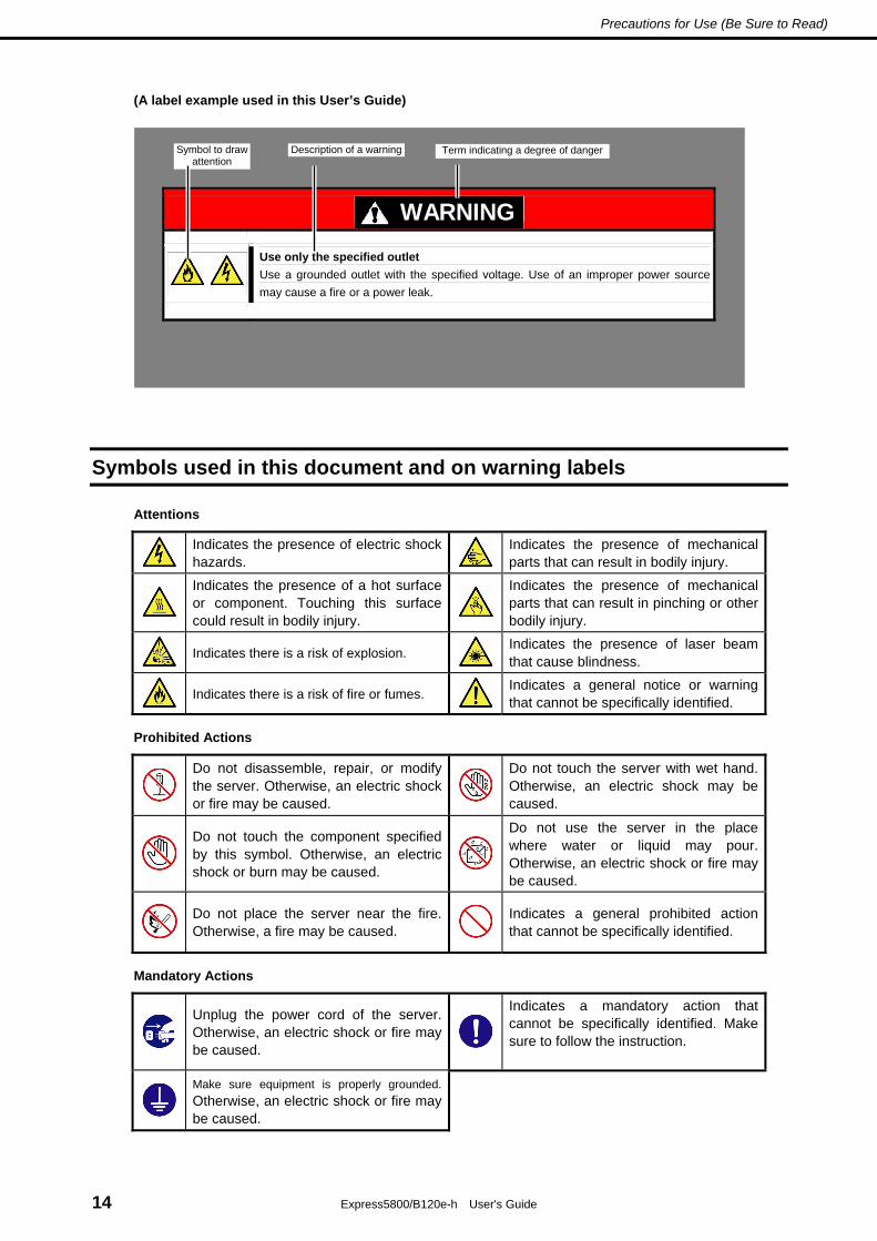
(A label example used in this User’s Guide)
Symbols used in this document and on warning labels
Attentions
Indicates the presence of electric shock hazards.
Indicates the presence of mechanical parts that can result in bodily injury.
Indicates the presence of a hot surface or component. Touching this surface could result in bodily injury.
Indicates the presence of mechanical parts that can result in pinching or other bodily injury.
Indicates there is a risk of explosion.
Indicates the presence of laser beam that cause blindness.
Indicates there is a risk of fire or fumes.
Indicates a general notice or warning that cannot be specifically identified.
Prohibited Actions
Do not disassemble, repair, or modify the server. Otherwise, an electric shock or fire may be caused.
Do not touch the server with wet hand. Otherwise, an electric shock may be caused.
Do not touch the component specified by this symbol. Otherwise, an electric shock or burn may be caused.
Do not use the server in the place where water or liquid may pour. Otherwise, an electric shock or fire may be caused.
Do not place the server near the fire. Otherwise, a fire may be caused.
Indicates a general prohibited action that cannot be specifically identified.
Mandatory Actions
Unplug the power cord of the server. Otherwise, an electric shock or fire may be caused.
Indicates a mandatory action that cannot be specifically identified. Make sure to follow the instruction.
Make sure equipment is properly grounded. Otherwise, an electric shock or fire may be caused.
WARNING
Use only the specified outlet Use a grounded outlet with the specified voltage. Use of an improper power source may cause a fire or a power leak.
Symbol to draw attention
Description of a warning Term indicating a degree of danger

Precautions for Use (Be Sure to Read)
Express5800/B120e-h User's Guide 15
Safety notes
This section provides notes on using the server safely. Read this section carefully to ensure proper and safe use of the server. For symbols, refer to Safety precautions.
WARNING
Do not use the server for services where human life may be at stake or high reliability is required.
This server is not intended for use in medical, nuclear, aerospace, mass transit or other applications where human life may be at stake or high reliability is required, nor is it intended for use in controlling such applications. We disclaim liability for any personal injury and property damages caused by such use of this server.
Do not disassemble, repair, or alter the server. Never attempt to disassemble, repair, or alter the server on any occasion other than described in this User's Guide. Failure to follow this instruction may cause an electric shock or fire as well as malfunctions of the server.
Do not attempt to remove lithium, NiMH, or Li-ion batteries.
The server contains the lithium, NiMH, or Li-ion battery (some optional devices have a lithium, NiMH, or Li-ion battery installed). Do not remove the battery. Placing a battery close to a fire or in the water may cause an explosion. When the server does not operate appropriately due to the dead battery, contact the store you purchased the product or your maintenance service company. Do not attempt to disassemble the server to replace or recharge the battery by yourself.
Do not use the server if any smoke, odor, or noise is present. If smoke, odor, or noise is present, immediately turn off the power of all of the CPU blades, turn off the power of Blade Enclosure, then contact your sales representative. Using the server in such conditions may cause a fire.
Do not insert needles or metal objects.
Do not insert needles or metal objects into ventilation holes in the server or openings in the optical disk drive. Doing so may cause an electric shock.
Do not install devices in any other chassis than the specified Blade Enclosure. Devices including CPU blades should be installed in the dedicated Blade Enclosure for their uses. Do not install the CPU blades and other devices in a chassis other than the Blade Enclosure. Failure to follow it may result in fire and/or electric shock to occur.
Do not use the server in an environment where corrosive gas is present
Do not install the server in a place subject to corrosive gases including sodium chloride, sulfur dioxide, hydrogen sulfide, nitrogen dioxide, chlorine, ammonia, or ozone. Do not install the server in an environment that contains dust, chemicals that accelerate corrosion such as NaCl or sulfur, or conductive materials. Failure to follow this warning may cause the wiring on the printed wiring board to short-circuit, leading to fire. If you have any questions, contact the store where you purchased the product or a maintenance service company.

Precautions for Use (Be Sure to Read)
Express5800/B120e-h User's Guide 16
WARNING
Do not handle the CPU blade if it is installed in the Blade Enclosure. To install or remove an option from the CPU blade, first turn off the power of the CPU blade and remove the CPU blade from the Blade Enclosure. If you touch any components on the CPU blade with it connected to Blade Enclosure, you may get an electric shock.
Do not install or remove more than one CPU blade at a time. Install or remove CPU blades one by one. If you install or remove more than one CPU blade at a time or a CPU blade with the cover of another slot removed, you may be electrically shocked.
CAUTION
Keep water or foreign matter away from the server.
Do not let any liquid such as water or foreign materials including pins or paper clips enter the server. Failure to follow this warning may cause an electric shock, a fire, or failure of the server. When such things accidentally enter the server, immediately turn off the power and disconnect the power plug from the outlet. Do not disassemble the server, and contact the store where you purchased the product or your maintenance service company.
Make sure to complete device installation. Always install an interface cable, CPU blade, Solid State Drive, and option board firmly. An incompletely installed device may cause a contact failure, resulting in smoking or fire.
Use only the specified interface cable. Use only interface cables authorized by NEC and locate a proper device and connector before connecting a cable. Using an unauthorized cable or connecting a cable to an improper destination may cause a short circuit, resulting in a fire. Also, observe the following notes on using and connecting an interface cable. • Do not use any damaged cable connector. • Do not step on the cable. • Do not place any object on the cable. • Do not use the server with loose cable connections. • Do not use any damaged cable.
High temperature Components including internal Solid State Drives in the server are extremely hot just after the server is turned off. Allow the surface to cool before installing/removing.
Avoid contact with the server during thunderstorms. Do not touch any part of the server including the cables when a thunderstorm is approaching. Also, do not connect or disconnect any devices. There may be a risk of electric shock from lightning strike.
Keep animals away from the server. Keep animals such as pets away from the server. Pet hair or other waste enters the server, which may cause a fire or electric shock.

Precautions for Use (Be Sure to Read)
Express5800/B120e-h User's Guide 17
Handling precautions (for proper operations)
Be sure to observe the following precautions for the proper functioning of the server. Ignoring the precautions may cause server malfunction or failure.
● General
– Do not block air vents of the CPU blades, Blade Enclosures, power supply units, and additional FAN
units.
– The CPU blade and internal option devices contain precision component that is easily affected by
drastic temperature change. If the device is used after storage or relocation, make sure that the
device is fully adapted to the operating environment.
– Do not touch the CPU blade terminals or on-board components by a bare hand nor place the CPU
blade directly on the desk.
– It is recommended to use options provided by NEC. Some memory devices and Solid State Drives of
other vendors are designed to be available for the server. If such an option causes the server to be
defected or damaged, you will be charged for the repair within the warranty period.
– Turn off the device that generates magnetism or radio wave (e.g., the cellular phone or PHS around
the server. Radio interference may cause malfunctions of the server.
● CPU blade
– N8400-215F/216F/217F/218F/219F/220F CPU blade should be installed in the Blade Enclosure
(SIGMABLADE).
– Install or remove CPU blades one by one.
– Hold the portions covered with metal plates when a CPU blade is installed or removed. To carry a
CPU blade, put it into the case in which the CPU blade was contained at the purchase and pack it
into the package.
– Check and adjust the system clock before the operation if any of the following conditions is
applicable.
After transportation
After storage
After the server is used following a period of disuse, in which storage conditions did not conform to
those that guarantee server operations (temperature: 10°C to 35°C; humidity: 20% to 80%).
– Check the system clock at the rough rate of once per month. When the system clock is installed in a
system requiring high time precision, it is recommended to use a time server (NTP server).
If the system clock is remarkably delayed or advanced as the passage of time in spite of adjustment,
contact your sales representative to ask maintenance.
– Store the unit under the storage condition (temperature: –10°C to 55°C, humidity: 20% to 80%,
without condensation).
– After turning off the power of a CPU blade once, turn on the power again after 30 seconds (after the
POWER lamp of the CPU blade goes on amber) have passed from the power-off.
– Remove a CPU blade after turning off the power of the CPU blade.

Precautions for Use (Be Sure to Read)
Express5800/B120e-h User's Guide 18
– Do not perform any of the following operation during POST (including similar operations from EM
card and external applications).
Press the POWER switch of the CPU blade.
Press the RESET switch of the CPU blade.
Remove the CPU blade from the Blade Enclosure.
Disconnect the power cord from the power unit of the Blade Enclosure.
● Solid state drive
– Confirm the slot to which the Solid State Drive is inserted. The slot for the Solid State Drive to be
connected to each CPU blade is defined previously.
Tips Maintenance service We offer periodic diagnosis and maintenance services by staff with expert knowledge of the maintenance of this server. We recommend that you make a periodic maintenance service contract with your maintenance service company to keep your server in good condition.

Precautions for Use (Be Sure to Read)
Express5800/B120e-h User's Guide 19
Handling precautions (for Anti-static Measures)
This product contains static-sensitive electronic components. Follow this measures below to avoid a failure caused by static electricity when installing or uninstalling any optional device.
● Wearing Anti-static Wrist Strap Or Anti-static Gloves
Wear a wrist strap on your wrist and connect the wire to the chassis. If there is no wrist strap, touch an
unpainted metal surface of the chassis connected to the ground to discharge static electricity from your
body before touching the component. Touch the metal part occasionally to discharge the static electricity
while working on the component.
● Checking the Workplace
– Work on an anti-static floor or concrete floor.
– If you work on a place where static electricity is likely to be generated (e.g. carpet), be sure to
provide anti-static protection.
● Using the Work Table
Place the server on a mat with Electrostatic Discharge (ESD) protection.
● Clothing
– Do not wear wool or synthetic clothes.
– Wear anti-static shoes.
– Remove any kind of metal accessories such as a ring, bracelet or wrist watch.
● Handling of Components
– Keep the component in an anti-static bag until you install it to the server.
– Hold the component by the edges to avoid touching any terminals or mounting parts.
– Place the component in an anti-static bag when storing or moving them.
● Handling of Cables
When connecting a cable (e.g., LAN cable), static electricity may also be charged due to friction against
the floor.
Connecting the charged cable with an I/O device may cause damage to the devices in the system. It is
recommended to use a product such as electrostatic discharge kit to eliminate the static charge before
connecting the cable.
● Installing and Uninstalling the Optional Device
– To avoid electric hazard and malfunction, be sure to turn off the power switch of the server and
unplug the power cord from the outlet before installing or uninstalling any optional device. If the
device is hot-swappable, you do not need to turn off the power switch and unplug the power cord.
– The device contains static-sensitive electronic components. When installing or uninstalling the
optional device, wear an anti-static wrist strap on your wrist to avoid a failure caused by the static
electricity. To use the strap, connect the wire to the chassis.

Precautions for Use (Be Sure to Read)
Express5800/B120e-h User's Guide 20
Handling precautions (Power-saving feature)
The server does not support power-saving features of OS such as Standby, Hibernate, and Sleep mode.

Precautions for Use (Be Sure to Read)
Express5800/B120e-h User's Guide 21
Using a computer extensively may affect different parts of your body. Here are tips you should follow while working on a computer to minimize strain on your body.
Keep proper posture
The basic body position for using a computer is sitting straight with your hands on the keyboard parallel with the floor, and your eyes directed slightly downward toward the monitor. With the proper posture described above, no unnecessary strain is applied on any part of your body, in other words when your muscles are most relaxed.
Working on the computer with bad posture such as hunching over or being too close to the monitor could cause fatigue or deteriorated eyesight.
Adjust the angle of your display
Most display units are designed for adjustment of the horizontal and vertical angles. This adjustment is important to prevent the screen from reflecting bright lights and to make the display contents easy to see. Working without adjusting the display to a comfortable angle makes it difficult for you to maintain a proper posture and you will get tired easily. Adjust the viewing angle before use.
Adjust the brightness and contrast of the display
Display screens have functions to control brightness and contrast. The most suitable brightness/contrast depends on age, individuals, and environment, so adjust it to suit your preferences. A too bright or too dark display is bad for your eyes.
Adjust the angle of keyboard
Some keyboards are ergonomically designed, which allow the angle to be adjusted. Adjusting the angle of the keyboard is effective to reduce tension on your shoulders, arms, and fingers.
Clean your equipment
Keeping your equipment clean is important not only for the appearance but also for functional and safety reasons. A dusty monitor makes it difficult to see the display contents, so clean it regularly.
Take rest breaks
When you feel tired, take a break. Light exercise is also recommended.
Tips for your health and safety

Express5800/B120e-h User's Guide 22
NEC Express5800 Series Express5800/B120e-h
General Description This chapter describes the features of the server and bundled software, and precautions on installation.
1. Introduction
2. Accessories
Verify the condition of your server's accessories.
3. Standard Features
Describes standard features of the server and system management utilities.
4. Names and Functions of Parts
This section describes the name of each part contained in this server.

1. Introduction
Express5800/B120e-h User's Guide 23
Chapter 1 General Description
1. Introduction
Welcome to the NEC Express5800/BladeServer series server.
This high performance and high density server is powered by the latest microprocessor "Intel® Xeon® processor.
NEC’s latest technology and architectures realize more space-saving and reduction of running cost than ever.
The server is designed with consideration of not only reliability but also expandability, which enables you to use it as a network server.
Read this document before using the server thoroughly to fully understand handling of Express5800 Series Server and appreciate its functions to the maximum extent.

2. Accessories
Express5800/B120e-h User's Guide 24
Chapter 1 General Description
2. Accessories
The carton box contains various accessories which are required for setup or maintenance. Make sure you have them all for future use.
• EXPRESSBUILDER *1
• Getting Started
*1 Documents are stored in EXPRESSBUILDER. Adobe Reader is required to read the documents so make sure you have it installed in your PC.
Make sure you have all accessories and inspect them. If an accessory is missing or damaged, contact your sales representative.
Important The chassis serial number plate and maintenance label is located on the
server. If the serial number does not match the number on the warranty, you
may not be guaranteed against failure even within the warranty period.
Contact your sales representative if they do not match.

3. Standard Features
Express5800/B120e-h User's Guide 25
Chapter 1 General Description
3. Standard Features
The server has the following standard features:
High performance
• Intel® Xeon® E5 processor
• DDR3-1333/1600 Registered DIMM and DDR3-1600 Unbuffered DIMM
• High-speed 10GBASE-KR interface (10Gbps supported), 2 ports
• High-speed disk access
High reliability
• Memory monitoring feature (correction of correctable error/detection of uncorrectable error (when
registered DIMM is used))
• Forced start-up with failed memory
• Bus parity error detection
• Temperature detection
• Error detection
• Internal voltage monitoring feature
• BIOS password feature
Management Utilities
• NEC ESMPRO
• Remote controlling featuer (EXPRESSSCOPE Engine 3)
• ExpressUpdate
• RAID System management utility (Universal RAID Utility)
Expandability
• Slot for Mezzanine card
• Large capacity memory of up to 512 GB
• Can upgrade to multi-processor system with up to two processors
• Two network ports
• Up to two Solid State Drives (2.5-inch) per a CPU blade can be connected
• USB2.0 interface (2 ports)

3. Standard Features
Express5800/B120e-h User's Guide 26
Chapter 1 General Description
Many built-in Features
• Software power-off
• Remote power-on feature
• AC-Link feature
Self-diagnosis
• Power On Self-Test (POST)
• Test and Diagnosis (T&D) utility
Easy setup
• EXPRESSBUILDER (setup utility)
• SETUP (BIOS SETUP utility)
Maintenance features
• Off-line Tools
• Memory dump feature using the DUMP switch

3. Standard Features
Express5800/B120e-h User's Guide 27
Chapter 1 General Description
3.1 Overview of Blade Server
In the Internet society diversified increasingly, every system administrator should have a request of "run many servers in less installation spaces".
If a server has only one server function, installation space increases at every extension even if the chassis size is minimized. In addition, an unexpected expenses, such as construction of a power supply and the purchase of the rack for storage, may occur.
With "Express5800/BladeSever Series", the server function is narrowed to necessity minimum and condensed on one board (CPU Blade) to realize space-saving and and intensive server.
The CPU Blade does not require any wiring or connection of a power supply and a cable.
Moreover, a processor, a memory, a solid state drive, a mezzanine card, and others can be installed as an option in the CPU Blade that has a server function.
Save space and
save power
Blade Enclosure
CPU blade
Increase in installation space
Increase in
consumptionpower

3. Standard Features
Express5800/B120e-h User's Guide 28
Chapter 1 General Description
3.2 Management Features
The hardware components of the server provide operation control/reliability features as shown below. Additionally, NEC ESMPRO Agent, which is provided in EXPRESSBUILDER, enables you to collectively manage the state of your systems. You can also monitor the server states from a PC to manage the network where NEC ESMPRO Manager provided in EXPRESSBUILDER is installed.
The features available on this server are as shown in the table below.
Function Availability Description
Shows physical hardware information.
Memory bank Shows physical memory information.
Device info Shows information specific to the server.
Hardware
CPU Shows physical CPU information.
System Shows logical CPU information and monitors the load factor. Shows logical memory information and monitors the status.
I/O device Shows information on I/O devices (floppy disk drive, serial ports, parallel port, keyboard, mouse, and video).
Monitors temperatures, fans, voltage, power supply, door, and others.
Temperature Monitors the temperature inside of the chassis.
Fan × Monitors the fans.
Voltage Monitors the voltage inside of the chassis.
Power supply × Monitors the power supply unit.
System environment
Door × Monitors Chassis Intrusion (open/close state of chassis cover or door).
Software Shows service, driver, and OS information.
Network Shows network (LAN) information and monitors packets.
BIOS Shows BIOS information.
Local polling Monitors the values of MIB items obtained by NEC ESMPRO Agent.
Storage Monitors controllers and storage devices including Solid State Drives.
File system Shows the file system configuration and monitors the free space.
RAID System / Disk Array Monitors the following RAID Controller: N8404-003F Storage and I/O Blade AD106b
Monitors OS stall using the Watch Dog Timer. Others*
Performs alert processing after an OS STOP error occurs.
: Supported. : Partially supported. ×: Unsupported.
*: Not displayed on the NEC ESMPRO Manager screen.
Tips NEC ESMPRO Manager and NEC ESMPRO Agent are supplied with the server
as standard. For how to install and use each software component, refer to the
explanation of the component.

3. Standard Features
Express5800/B120e-h User's Guide 29
Chapter 1 General Description
3.3 About the Monitoring of Chassis Sensors
The fan and the power supply units installed in Blade Enclosure (SIGMABLADE) are monitored by the EM card. The information that the EM card monitors can be confirmed by the Information of EM Card state/constitution of NEC ESMPRO Manager.
In Enclosure → Power Supply tree in the Information of server state/constitution of NEC ESMPRO Manager, the status of the power circuit of CPU blade is displayed.
3.4 Firmware and Software Version Management
Use of NEC ESMPRO Manager and ExpressUpdate Agent allows you to manage versions of firmware and software as well as update them by applying update packages.
This function automatically updates multiple modules without stopping the system just by specifying the application of an update package from NEC ESMPRO Manager.

4. Names and Features of Component
Express5800/B120e-h User's Guide 30
Chapter 1 General Description
4. Names and Features of Component
This section describes the names and features of the components in the device.
4.1 CPU Blade
This section describes the names, installation positions, and features of the sections on the CPU blade.
CPU blade
(1) DIMM socket (CPU#2) CPU2_DIMM3, CPU2_DIMM7, CPU2_DIMM4, CPU2_DIMM8 from top
(2) DIMM socket (CPU#2) CPU2_DIMM6, CPU2_DIMM2, CPU2_DIMM5, CPU2_DIMM1 from top
(3) DIMM socket (CPU#1) CPU1_DIMM1, CPU1_DIMM5, CPU1_DIMM2, CPU1_DIMM6 from top
(4) DIMM socket (CPU#1) CPU1_DIMM8, CPU1_DIMM4, CPU1_DIMM7, CPU1_DIMM3 from top
(5) SSD cable connector Connector to connect a cable for Solid State Drivethat is mounted on air duct.
(6) SSD1 cable connector Connector to connect a cable for Solid State Drive#0 that is mounted on air duct.
(7) SSD2 cable connector Connector to connect a cable for Solid State Drive#1 that is mounted on air duct.
(8) Mezzanine card slot (Type 2) Slot to install mezzanine card for blade. The slot number is "MEZ2".
(9) Mezzanine card slot (Type 1) Slot to install mezzanine card for blade. The slot number is "MEZ1".
(10) Connector for Internal Flash Memory Connector to install Internal Flash Memory.
(11) Connector for Trusted Platform Module Kit Connector to install Trusted Platform Module Kit .
(12) Connector for LAN riser card Connector to install LAN riser card.
(13) Socket for processor #1 (CPU #1) Socket tor optional processor #1 (CPU #1) (CPU#2 and CPU heat sink are installed.)
(14) Socket for processor #2 (CPU #2) Socket tor optional processor #2 (CPU #2) (CPU#2 and CPU heat sink are not installed.)
(15) SUV cable connector
(16) Eject lever
(1)
(2)
(3)
(4)
(5) (6) (7)
(8)
(9)
(10)
(12)
(11)
(13) (14)
(15)
(16)

4. Names and Features of Component
Express5800/B120e-h User's Guide 31
Chapter 1 General Description
CPU Blade Access Side
1
DMP
RST
2
ID
(1) POWER lamp The lamp goes on green when the CPU blade is powered on. The lamp goes on amber when the CPU blade is powered off but the power is supplied from the power supply unit.
(2) POWER switch The switch is intended to turn on or off the power of the CPU blade itself. Pressing the switch for 4 seconds or longer causes the power supply to be turned off forcibly.
(3) STATUS lamp (green/amber/red) The lamp indicates the status of the CPU blade. See "Lamp Indications" described later for the indications and meanings of the lamp.
(4) DUMP switch Press this switch to run the memory dump.
(5) LAN1 Link/Access lamp (green) The lamp goes on when LAN port 1 is connected to the network. The lamp blinks when data is being transmitted.
(6) RESET switch Press this switch to reset the CPU blade.
(7) LAN2 Link/Access lamp (green) The lamp lights when LAN port 2 is connected to the network. The lamp blinks when data is being transmitted.
(8) ID/BMC RESET switch Press this switch to turn on or off the ID lamp. Pressing this switch toggles lamp ON/OFF. Refer to Chapter 1 (7.2 BMC Reset) in Maintenance Guidefor BMC RESET switch.
(9) ID lamp The lamp is intended to identify the CPU blade in the system. The lamp is lit by a switch or software command.When the recognize command is received from NEC ESMPRO Manager and when the ID switch is pressed, the lamp goes on. You may use the remote control feature of EXPRESSSCOPE Engine 3 (BMC) to perform the same operation as using the ID switch on the server.
(10) Eject lever Pull the lever to remove the CPU blade from the Blade Enclosure.
(11) SUV cable connector This connector sends or receives various signals. The K410-150(00) SUV cable (separately-priced or provided with the SIGMABLADE) is connected to this connector.
(12) SSD Access lamp If the server is equipped with optional Solid State Drives, the lamp goes on while optional Solid State Drive is being accessded. (upper: #0 / lower: #1)
(13) Slide tag A label on which the model number and serial number are described is attached this slide tag. You can check the label contents by pulling this slide tag.
1
DMP
RST2
ID
(1)
(2) (3)
(4) (5)
(6) (7)
(8)
(9)
(10)
(11)
(12)
(10)
(13)
(13)
(12)

4. Names and Features of Component
Express5800/B120e-h User's Guide 32
Chapter 1 General Description
External View
With top cover installed
(1) Top cover (2) Front frame
With top cover removed
(1) SSD cable (2) SSD bay 0
(3) SSD bay 1 (4) Air duct
(1)
(2)
(4)
(1)
(3)
(2)

4. Names and Features of Component
Express5800/B120e-h User's Guide 33
Chapter 1 General Description
With top cover, air duct, and front frame removed
(1) DIMM
(1)
(1)

4. Names and Features of Component
Express5800/B120e-h User's Guide 34
Chapter 1 General Description
4.2 Solid State Drive (SSD)
The Solid State Drive is an optional device. An operating system may be installed in the Solid State Drive. Handle it carefully.
(1) Solid state drive
(2) SATA connector Connect SSD cable to this connector.
(3) Screws (2)
(4) SSD mount bracket Provided with screws.
(1)
(2)
(4)
(3)

4. Names and Features of Component
Express5800/B120e-h User's Guide 35
Chapter 1 General Description
4.3 Lamp Indications
This section describes the positions and display meanings of the lamps on the CPU blade and other devices.
CPU Blade
The CPU blade has 7 lamps.
1
DMP
RST
2
ID
4.3.1 POWER Lamp The POWER lamp lights green while the power of the CPU blade is on. The lamp lights amber when the CPU blade is powered off but the power is supplied from the power supply unit. The lamp is off if the power is not supplied to the system.
SSD Access lamp (#0)
POWER lamp
STATUS lamp
ID lamp
LAN2 Link/Access lamp
LAN1 Link/Access lamp
SSD Access lamp (#1)

4. Names and Features of Component
Express5800/B120e-h User's Guide 36
Chapter 1 General Description
4.3.2 STATUS Lamp The STATUS lamp stays lit in green when the CPU blade is in successful operation. When the STATUS lamp is flashing in amber or red, it indicates that the system has failed. In addition, you can view the detailed information on error message on virtual LCD when the STATUS lamp is flashing in amber or red. You can use the virtual LCD through the Web browser of EXPRESSSCOPE Engine 3 (BMC) or NEC ESMPRO Manager.
The following table lists indications of the STATUS lamp and virtual LCD, descriptions, and actions to take.
If an error occurs, contact your sales representative.
Tips If the CPU blade has the NEC ESMPRO installed, you can view the error log to identify
the cause of a trouble.
Status of STATUS lamp
Color Description Action
On Green The CPU blade is operating normally. –
Off – The power is turned off. Turn on the power.
On Red BMC is being initialized. 1. Wait until the lamp goes off. 2. If the lamp still goes on, check
installation status of the CPU blade.
BMC does not work normally due to incorrect installation of LAN riser card.
If the indication of ID lamp does not change even when the ID switch is pressed, contact your sales representative. The virtual LCD indication cannot be obtained because BMC is not working.
Flash Red
An error occurred. Identify the error cause according to Chapter 3 (1. POST Error Message) in Maintenance Guide.
Flash Amber A warning level error occurred. Identify the error cause according to Chapter 3 (1. POST Error Message) in Maintenance Guide.
Tips If the CPU blade is powered off while the STATUS lamp is flashing in amber or red, the
indication of the STATUS lamp is retained except for certain factors. When the CPU blade
is powered on, the STATUS lamp goes on green (normal status).

4. Names and Features of Component
Express5800/B120e-h User's Guide 37
Chapter 1 General Description
4.3.3 LAN (1 - 2) Link/Access Lamps The lamp blinks when data is being transmitted through the LAN port. When the CPU blade is powered on and the LAN cable is connected, the lamp on LAN port for which the link is being established goes on. The connection of LAN port is physically controlled by the EM card and the switch module installed in the Blade Enclosure.
To check connection status of LAN port, refer to the User's Guides of the EM card and the switch module installed in the Blade Enclosure.
4.3.4 ID Lamp Pressing the ID switch brings the lamp to light, and pressing again brings the lamp to go off. The ID lamp is intended to identify a specific CPU blade in the rack in which more than one CPU blade is installed. Making this lamp being lit can help the maintenance work to identify the faulty device.
If you press the ID switch, the lamp goes on. When the recognize command is received from management software such as NEC ESMPRO Manager, the lamp also goes on.
You may use the remote control feature of EXPRESSSCOPE Engine 3 (BMC) to perform the same operation as using the ID switch on the server.
4.3.5 SSD Access Lamp The lamp lights while accessing to a Solid State Drive occurs (however, if the Solid State Drives are operated in the RAID System, the lamp operates only in the OS boot status).
The lamp is lit amber if a Solid State Drive cannot be interfaced with the CPU blade correctly due to a hardware fault in the CPU blade or another failure.
In the RAID System, the lamp blinks green or amber alternately while the Logical Drives are rebuilt (this does not indicate an error). After the rebuilding completes, the lamp returns to the normal indication. If the rebuilding fails, the lamp is lit amber.

Express5800/B120e-h User's Guide 38
NEC Express5800 Series Express5800/B120e-h
Preparations
This chapter describes preparations for using this server.
1. Installing Internal Optional Devices
You can skip this section if you did not purchase any optional devices.
2. Ideal Location and Connection
You must place the server in an ideal location and connect cables following this section.

1. Installing Internal Optional Devices
Express5800/B120e-h User's Guide 39
Chapter 2 Preparations
1. Installing Internal Optional Devices
This section describes the instructions for installing supported optional devices and precautions. If you did not purchase any optional device requiring installation, you may skip this section.
Important • We recommend that optional devices be installed by a maintenance service
staff from your maintenance service company, who has specialized knowledge
of this server.
• Use only the devices and cables specified by NEC. You will be charged to
repair damages, malfunctions, and failures caused by the use of any devices or
cables not specified for use with this server even within the warranty period.
• When you made any change to the hardware configuration, make sure to
update the system (Refer to the Installation Guide for details.).
1.1 Safety Precautions
Be sure to observe the following precautions to install and remove optional devices properly and safely.
WARNING
Be sure to observe the following precautions to use the server safety. Failure to observe the precautions may cause death or serious injury. For details, refer to Safety precautions in Precautions for Use.
• Do not disassemble, repair, or modify the server.
• Do not remove the lithium battery, NiMH battery, or Li-ion battery.
• Disconnect the power plug when installing and removing devices.
CAUTION
Be sure to observe the following precautions to use the server safely. Failure to observe the precautions may cause burns, injury, and property damage. For details, refer to Safety precautions in Precautions for Use.
• Pay attention to hot surface.
• Make sure to complete installation.
• Do not install with the top cover, air duct, and/or front frame removed.
• Do not get your fingers caught.

1. Installing Internal Optional Devices
Express5800/B120e-h User's Guide 40
Chapter 2 Preparations
1.2 Overview of Installation and Removal
To install or remove an optional device or Solid State Drive installed in the CPU blade, you should first remove the CPU blade from the Blade Enclosure. Refer to Chapter 2 (2. Installation and Connection) for details.
Important Remove the target CPU blade only. Do not remove any other blank cover or CPU
blade from another slot. Be sure to install or remove the CPU blade one by one.
CAUTION
Be sure to observe the following precautions to use the server safely. Failure to observe the precautions may cause burns, injury, and property damage. For details, refer to Safety precautions in Precautions for Use.
• Pay attention to hot surface.
• Make sure to complete installation.
• Do not install with the top cover, air duct, and/or front frame removed.
• Do not get your fingers caught when installing components
1. After the shutdown processing for the CPU blade to be removed, turn off the power of the CPU blade.
Refer to Chapter 3 (7. Power-off of Blade Server).
2. Take the CPU blade out from the Blade Enclosure.
Refer to the User's Guide of the Blade Enclosure.
3. Put the CPU blade on an anti-static sheet with little dust.
4. Remove the top cover. In addition, remove the air duct if needed.
Refer to Chapter 2 (1.3 Installation and Removal Procedure (Common section)).
5. Perform installation or removal procedure for the component required for your system.
Refer to sections in Chapter 2 (1.4 Processor (CPU) through 1.10 Internal Flash Memory).
6. Install the top cover. In addition, install the air duct if needed.
Refer to Chapter 2 (1.3 Installation and Removal Procedure (Common section)).
7. Install the CPU blade in Blade Enclosure.
Refer to the User's Guide of Blade Enclosure.
This completes installation or removal of internal optional devices.
Continue the setup with reference to Chapter 2 (2.2 Connecting Peripheral Devices).

1. Installing Internal Optional Devices
Express5800/B120e-h User's Guide 41
Chapter 2 Preparations
1.3 Installation and Removal Procedure (Common section)
Take steps below to install or remove top cover and air duct.
1.3.1 Removal of top cover Take steps below to remove the top cover.
1. After the shutdown processing for the CPU blade to be removed, turn off the power of the CPU blade.
2. Take the CPU blade out from the Blade Enclosure.
Refer to the User's Guide of the Blade Enclosure.
3. Put the CPU blade on an anti-static sheet with little dust.
4. Remove the two screws that secure the top cover.
5. Firmly hold the top cover, move it slightly toward the rear of the CPU blade, then lift the cover to
remove it from the CPU blade.
Important Pay attention not to make the cover hit any electronic component on the CPU blade.

1. Installing Internal Optional Devices
Express5800/B120e-h User's Guide 42
Chapter 2 Preparations
1.3.2 Removal of air duct Take steps below to remove air duct.
1. Remove the two screws from the front frame that secures the air duct.
2. Pull the front frame toward the front of CPU blade, and remove it.
3. Remove the three SSD cable connectors.
This step is not required if the N8403-042F diskless kit has been installed. Proceed to Step 4.
Important Pay attention to orientation of guide key on SSD cable connector.

1. Installing Internal Optional Devices
Express5800/B120e-h User's Guide 43
Chapter 2 Preparations
4. Remove the two screws securing the air duct.
5. Firmly hold the air duct, and lift it to remove.
Important • Pay attention not to make the air duct hit any electronic component on the CPU
blade.
• Pay attention not to damage the SSD cable.
• If SSD is installed on air duct, carefully handle the air duct not to give any
shock to SSD.

1. Installing Internal Optional Devices
Express5800/B120e-h User's Guide 44
Chapter 2 Preparations
1.3.3 Installation of top cover and air duct To install top cover and air duct, perform installation steps (Chapter 2 (1.3.1 Removal of top cover) and (1.3.2 Removal of air duct)) in reverse order.
Note the following when installing these components.
● Installing removed components exactly as they were
Install the components and cables, which were removed and disconnected for addition of an option,
exactly as they were. Assembling without a component being installed or a cable being disconnected
causes the server to malfunction.
● Confirming that no parts such as screws are left in the server
Confirm that particularly conductive parts such as screws are not left in the server. Turning on the power
with a conductive part on the mother board or cable terminal causes the server to malfunction.
● Confirming the cooling effect in the server
Confirm that the ventilating holes are not covered with an internally connected cable. Insufficient cooling
effect raises the internal temperature, which causes the server to malfunction.
● Confirming operation with a tool
Some additional devices require the diagnostic utility or BIOS SETUP utility to check if they are installed
correctly. For details, see the procedure for installing the target device.

1. Installing Internal Optional Devices
Express5800/B120e-h User's Guide 45
Chapter 2 Preparations
1.4 Processor (CPU)
The server may have another CPU installed in addition to the factory-installed CPU (Intel® Xeon® Processor).
Important • The CPU to be added must have the same specification (the core voltage,
clock, and others) as the CPU already installed.
• The CPU is extremely sensitive to static electricity. Make sure to touch the
metal frame of the server to discharge static electricity from your body before
handling the CPU. Do not touch the CPU pins by a bare hand or place the CPU
directly on the desk. For static notes, refer to “Handling precautions (for
Anti-static Measures)”.
• Do not operate the system until confirming that the additionally installed CPU
is in normal state.
• Make sure to use the CPU authorized by NEC. Installing a third-party CPU may
cause a failure of the CPU as well as the server. Repair of the server due to
failures or damage resulted from installing such a CPU will be charged.
Tips An optional CPU of different revision may be contained in the system. If the CPU of
different revision is installed, Windows 2003 logs the following information in system log of
Event Viewer. However, this event does not affect the system operation.
CPU #1 (to be installed below the heat sink)
CPU #2 (to be installed below the socket cover)
CPU blade

1. Installing Internal Optional Devices
Express5800/B120e-h User's Guide 46
Chapter 2 Preparations
1.4.1 Installation Install the CPU in the following procedure.
1. Remove the top cover and air duct according to Chapter 2 (1.3.1 Removal of top cover) and (1.3.2 Removal
of air duct).
2. Confirm the position of the CPU socket.
3. Push down the socket lever once to unlatch it from the hook, then slowly open the lever until it stops.
4. Lift the CPU socket holder.
Important You will see the CPU socket contacts. Do not touch the socket contacts.
5. Remove the socket cover.
Important Keep the removed socket cover for future use. Always attach the socket cover if the
processor is removed from the socket.

1. Installing Internal Optional Devices
Express5800/B120e-h User's Guide 47
Chapter 2 Preparations
6. Put the additional processor on the CPU socket slowly and gently.
For easy installation, hold edges of processor with your thumb and index fingers so that the notch is aligned
with the key on the CPU socket.
Important • Be sure to hold the processor only at the edges. Pay attention not to touch the
bottom of the processor (pin section).
• Note the direction of the CPU. To prevent the CPU from being inserted into the
mating socket incorrectly, a pin mark is put on each of the CPU and the socket.
Check the pin marks to insert the CPU into the socket correctly.
• Insert the processor while aligning the notch on the processor with the key
section on the CPU socket.
7. Push the CPU lightly to the socket, and push down the CPU socket holder.

1. Installing Internal Optional Devices
Express5800/B120e-h User's Guide 48
Chapter 2 Preparations
8. Push down the lever to secure the CPU.
9. Put the heat sink on the CPU.
Take care not to touch the cool sheet with your hand.
Important Install the heat sink in correct direction as shown in the figure below.
Front Rear

1. Installing Internal Optional Devices
Express5800/B120e-h User's Guide 49
Chapter 2 Preparations
10. Secure the heat sink with four screws.
When installing the CPU heat sink, temporarily tighten the four screws on cater corner, then tighten them
securely after making sure that the heat sink has been seated in parallel with the CPU socket.
1
2
3
4
11. Install the components having been removed.
12. Install the CPU blade having been removed to the Blade Enclosure according to the User's Guide of the
Blade Enclosure.
13. If "ACPI uni-processor PC" or "ACPI single-processor PC" is shown in Driver tab under Computer,
change it to "ACPI multi-processor PC". Reboot the system according to the message, and update the
system. (Refer to Installation Guide.)
Perform the following procedure if:
– The system is running under the Windows operating system
– The system is under the 1-CPU configuration
Any change is not required if "ACPI multi-processor PC" is set in Driver tab under Computer.
1. Installing Internal Optional Devices
Express5800/B120e-h User's Guide 50
Chapter 2 Preparations
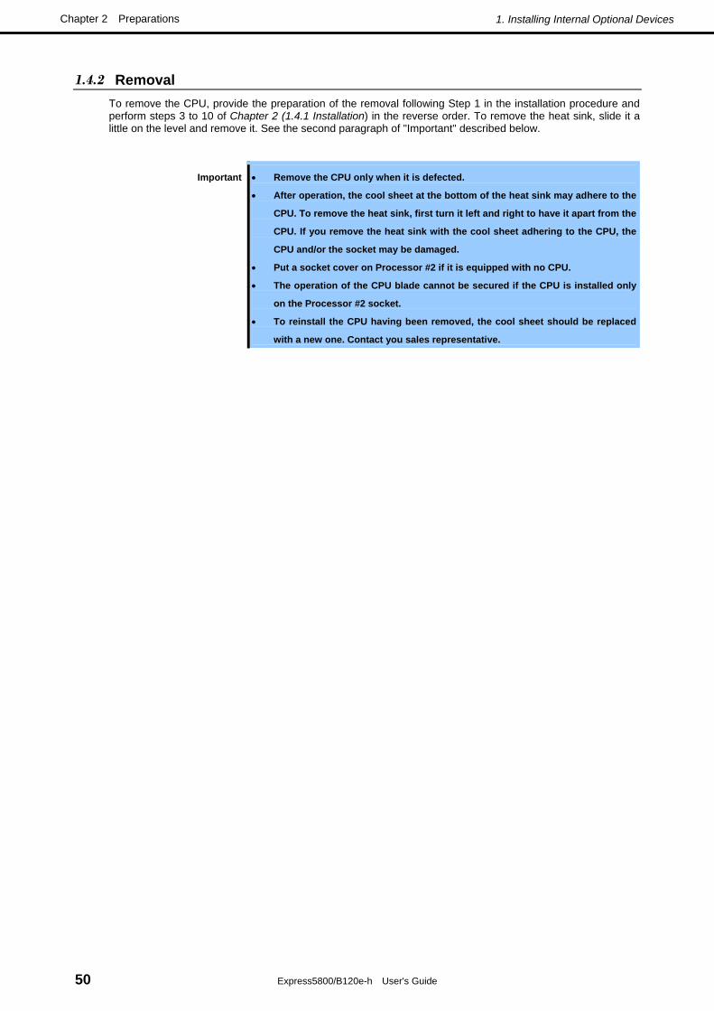
1.4.2 Removal To remove the CPU, provide the preparation of the removal following Step 1 in the installation procedure and perform steps 3 to 10 of Chapter 2 (1.4.1 Installation) in the reverse order. To remove the heat sink, slide it a little on the level and remove it. See the second paragraph of "Important" described below.
Important • Remove the CPU only when it is defected.
• After operation, the cool sheet at the bottom of the heat sink may adhere to the
CPU. To remove the heat sink, first turn it left and right to have it apart from the
CPU. If you remove the heat sink with the cool sheet adhering to the CPU, the
CPU and/or the socket may be damaged.
• Put a socket cover on Processor #2 if it is equipped with no CPU.
• The operation of the CPU blade cannot be secured if the CPU is installed only
on the Processor #2 socket.
• To reinstall the CPU having been removed, the cool sheet should be replaced
with a new one. Contact you sales representative.
1. Installing Internal Optional Devices
Express5800/B120e-h User's Guide 51
Chapter 2 Preparations
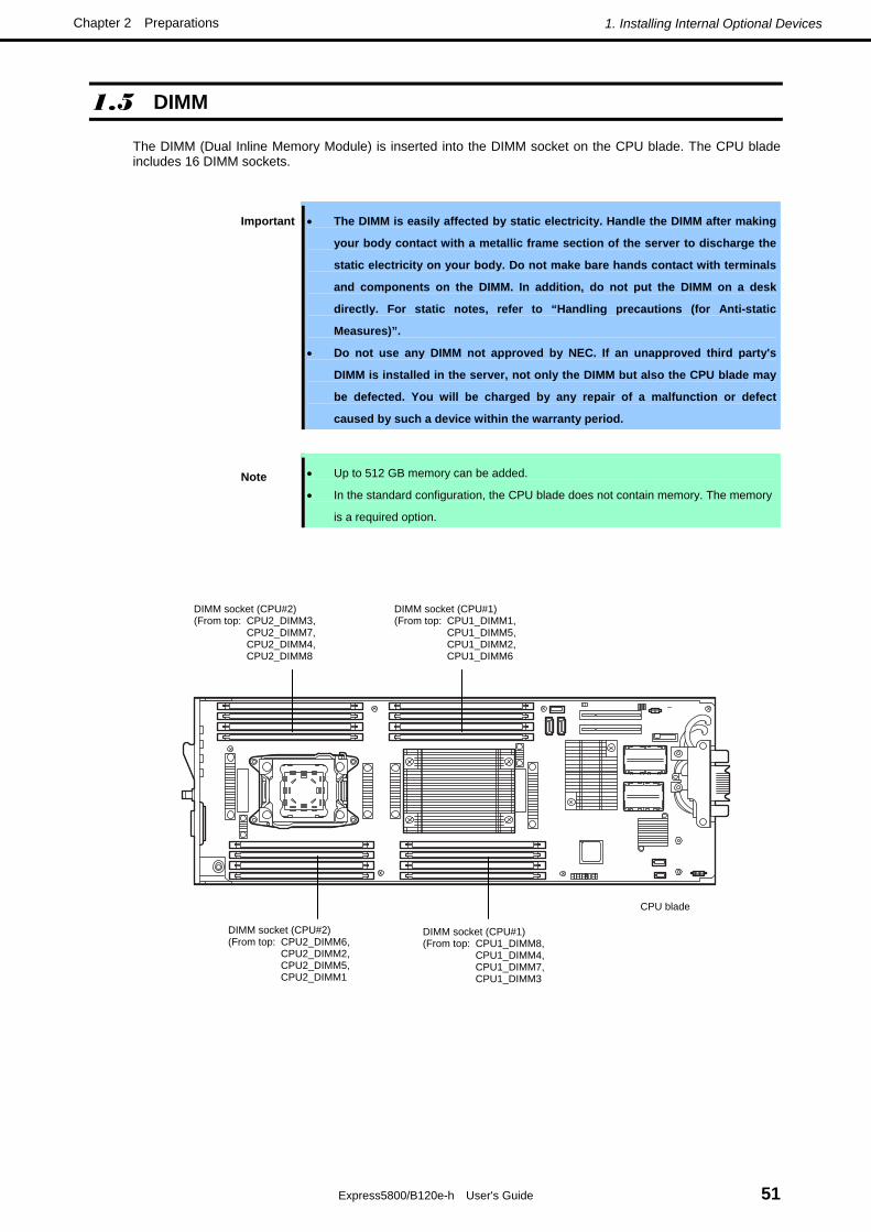
1.5 DIMM
The DIMM (Dual Inline Memory Module) is inserted into the DIMM socket on the CPU blade. The CPU blade includes 16 DIMM sockets.
Important • The DIMM is easily affected by static electricity. Handle the DIMM after making
your body contact with a metallic frame section of the server to discharge the
static electricity on your body. Do not make bare hands contact with terminals
and components on the DIMM. In addition, do not put the DIMM on a desk
directly. For static notes, refer to “Handling precautions (for Anti-static
Measures)”.
• Do not use any DIMM not approved by NEC. If an unapproved third party's
DIMM is installed in the server, not only the DIMM but also the CPU blade may
be defected. You will be charged by any repair of a malfunction or defect
caused by such a device within the warranty period.
Note • Up to 512 GB memory can be added.
• In the standard configuration, the CPU blade does not contain memory. The memory
is a required option.
CPU blade
DIMM socket (CPU#2) (From top: CPU2_DIMM3, CPU2_DIMM7, CPU2_DIMM4, CPU2_DIMM8
DIMM socket (CPU#1) (From top: CPU1_DIMM1, CPU1_DIMM5, CPU1_DIMM2, CPU1_DIMM6
DIMM socket (CPU#2) (From top: CPU2_DIMM6, CPU2_DIMM2, CPU2_DIMM5, CPU2_DIMM1
DIMM socket (CPU#1) (From top: CPU1_DIMM8, CPU1_DIMM4, CPU1_DIMM7, CPU1_DIMM3

1. Installing Internal Optional Devices
Express5800/B120e-h User's Guide 52
Chapter 2 Preparations
1.5.1 Adding Order and Precautions
• Adding order depends on the number of CPUs installed.
– 1-CPU configuration:
Install DIMMs starting from the smallest DIMM slot number.
– 2-CPU configuration:
Alternately install DIMMs starting from the smallest DIMM slot number of each CPU.
• Install DIMM one by one.
• Install DIMMs starting from the largest capacity and from the smallest slot number.
• Registered DIMMs and Unbuffered DIMMs cannot be mixedly installed. If installed mixedly, the CPU blade
will fail to operate correctly.
• If the CPU blade does not have CPU#2 installed, DIMM slots CPU2_DIMM1 to CPU2_DIMM8 are
unavailable.
1.5.2 Installation Install the DIMM on the CPU blade according to the following procedure:
1. Remove the top cover and air duct according to Chapter 2 (1.3.1 Removal of top cover) and (1.3.2
Removal of air duct).
2. Push the DIMM into the socket straight.
If the DIMM is inserted into the DIMM socket, the lever is automatically closed.
Important • Make sure of the orientation of the DIMM. The connecting side of the DIMM has
a cut-out to prevent an incorrect insertion.
• Use extreme care when inserting a DIMM. Applying too much pressure can
damage the DIMM and/or connector.
3. Close the lever firmly.
4. If you need to install two or more DIMMs, install them according to steps 2 through 4.
5. Install the top cover and air duct according to Chapter 2 (1.3.3 Installation of top cover and air duct).
6. Install the CPU blade having been removed to the Blade Enclosure according to the User's Guide of
the Blade Enclosure.
7. Make sure that no error message appears on the POST screen.
If any error messages are displayed, refer to Chapter 3 (1. POST Error Message) in "Maintenance
Guide".

1. Installing Internal Optional Devices
Express5800/B120e-h User's Guide 53
Chapter 2 Preparations
8. Run SETUP and select menus in the order of Advanced and Memory Configuration to make sure
that the status of installed DIMM is "Normal" (refer to Chapter 2(1. System BIOS) in "Maintenance
Guide".).
9. Set the paging file size to a value larger than the recommended value (installed memory * 1.5) (for
Windows). Refer to Installation Guide for more information.
1.5.3 Removal To remove DIMMs, remove the top cover and air duct according to Chapter 2 (1.3.1 Removal of top cover) and (1.3.2 Removal of air duct), and then perform steps in Chapter 2 (1.5.2 Installation) in reverse order.
After DIMMs were removed, make sure that no error message appears in POST.
If any error messages are displayed, refer to Chapter 3 (1. POST Error Message) in "Maintenance Guide".
Run SETUP and select Yes after selecting Advanced → Memory Configuration → Memory Retest. Restart the CPU blade to clear the error information of the removed DIMM (refer to Chapter 2 (1. System BIOS) in "Maintenance Guide".).
Set the paging file size to a value larger than the recommended value (installed memory * 1.5) (for Windows). Refer to the Installation Guide for more information.
Note To remove the defected DIMM, check the error message appearing in POST or NEC
ESMPRO to confirm the CPU blade on which the detected DIMM is installed.

1. Installing Internal Optional Devices
Express5800/B120e-h User's Guide 54
Chapter 2 Preparations
1.6 Mezzanine Card
The CPU blade can contain two mezzanine cards for blade which allows an extension of network or a file device feature.
To install a mezzanine card, use the mezzanine card slot installed on the CPU blade. The mezzanine card slot is factory-installed on the CPU blade.
Important • The mezzanine card is extremely sensitive to static electricity. Make sure to
touch the metal frame of the server to discharge static electricity from your
body before handling the mezzanine card. Do not touch the terminals and parts
on the mezzanine card by a bare hand and place the cards directly on the desk.
For static notes, refer to “Handling precautions (for Anti-static Measures)”.
• A combination of boards which can be installed in the Blade Enclosure under
certain restrictions. Contact your sales representative for details.
Note Some optional mezzanine cards use expansion ROMs on the boards. Refer to the manual
shipped with the board to check whether the expansion ROMs should be required. Use
the BIOS setup utility "SETUP" for the setting. Refer to Chapter 2 (1. System BIOS) in
"Maintenance Guide".
CPU blade
Mezzanine card slot (Type 2)
Mezzanine card slot (Type 1)

1. Installing Internal Optional Devices
Express5800/B120e-h User's Guide 55
Chapter 2 Preparations
1.6.1 Notes Note the followings in the installation or removal of the mezzanine card.
• Be careful not to make your hands touch the terminals of the mezzanine card slot directly. If you do not
keep it, the oil and/or dirt on the hands may adhere to the terminals to result in contact failure.
• For the optional ROMs on the unbootable LAN device, set "Disabled" with the BIOS SETUP utility.
• If a bootable mezzanine card (such as Fibre Channel controller or LAN card) is installed, check the boot
priority on the Boot menu of the BIOS SETUP utility.
• The slot number for the Type 1 mezzanine card is "MEZ1", and "MEZ2" for Type 2 mezzanine card.
• 1000BASE Adapter (4ch) (N8403-077F) can be installed only in the Type 2 mezzanine card slot.
1.6.2 Installation Install a mezzanine card in mezzanine card slot in the following procedure.
Important There are two types of mezzanine card for blade, Type 1 and Type 2.
The Type 1 mezzanine card can be installed in either of connectors Type 1 and Type
2.
The Type 2 mezzanine card can be installed in Type 2 connector only.
To install the mezzanine card, start installation from the bottom slot (for Type 1).
Note Before installing mezzanine card, make sure that the connection port on the card engages
with the connector on the mezzanine card slot.
1. Remove the top cover and air duct according to Chapter 2 (1.3.1 Removal of top cover) and (1.3.2
Removal of air duct).
2. Confirm the position of the slot to install the mezzanine card.

1. Installing Internal Optional Devices
Express5800/B120e-h User's Guide 56
Chapter 2 Preparations
3. From top of the CPU blade, position the connector of the mezzanine so that it aligns the connector of
the mezzanine card slot, and insert the mezzanine card straight into the slot.
Type 1
Type 2
Important • Do not make your body contact with the terminals on the board. Some
malfunction may occur if the board is installed with dirt and/or oil adhering to
the terminals.
• Insert the mezzanine card straight into the connector. The terminal or
connector may be damaged if it is inclined.
• If the board cannot be installed securely, remove the board once and then
install it again. Adding excess force to the board may cause the board to be
damaged. Keep the removed dummy memory for future use.
4. Push the connector of mezzanine card with fingers firmly toward the CPU blade to connect the card to
the slot.
5. Tighten the two fixing screws to fix the mezzanine card to the spacer on the CPU blade.
6. Install the component you have removed in earlier steps.
7. Install the CPU blade having been removed to the Blade Enclosure according to the User's Guide of
the Blade Enclosure.
8. Turn on the power of the CPU blade. Make sure that no error message appears in POST.
If any error messages are displayed, refer to Chapter 3 (1. POST Error Message) in "Maintenance
Guide".
9. If needed, run the BIOS configuration utility of the installed board to provide setup for the board.
The existence of the utility and its start and operation procedures vary depending on the type of the
board. Refer to the documentation coming with the board for details.

1. Installing Internal Optional Devices
Express5800/B120e-h User's Guide 57
Chapter 2 Preparations
1.6.3 Removal To remove Mezzanine card, remove the top cover and air duct according to Chapter 2 (1.3.1 Removal of top cover) and (1.3.2 Removal of air duct), and then perform steps in Chapter 2 (1.6.2 Installation) in reverse order.
After Mezzanine card is removed, make sure that no error message appears in POST.
If any error messages are displayed, refer to Chapter 3 (1. POST Error Message) in "Maintenance Guide".
Important • Pay attention not to make the air duct hit any electronic component on the CPU
blade.
• Pay attention not to make the air duct hit any electronic component on the CPU
blade.
• If SSD is installed on air duct, handle the air duct with care not to give any
shock to SSD.
• Pay attention to orientation of guide key of SSD cable connector.

1. Installing Internal Optional Devices
Express5800/B120e-h User's Guide 58
Chapter 2 Preparations
1.7 Solid State Drive (SSD)
The CPU blade can contain up to two 2.5-inch Solid State Drive.
See the next and the subsequent sections for installation order and installation location.
Important • The Solid State Drive is extremely sensitive to static electricity. Make sure to
touch the metal frame of the server to discharge static electricity from your
body before handling the Solid State Drive. Do not touch the terminals and
parts on the Solid State Drive by a bare hand and place the Solid State Drive
directly on the desk. For static notes, refer to “Handling precautions (for
Anti-static Measures)”.
• An optional Solid State Drive may contain operating system. Be very careful
when handling the drive.
• Do not use any Solid State Drives not approved by NEC. If an unapproved third
party's Solid State Drive is installed in the CPU blade, not only the Solid State
Drive but also the CPU blade may be defected.
• If Solid State Drives of different disk capacities co-exist in the CPU Blade, the
system can operate normally. However, to use the Solid State Drives in RAID
configuration, use Solid State Drives of the same model number.
• An SSD bracket and screws are not provided with the optional Solid State
Drive. Use them that come with the CPU blade.

1. Installing Internal Optional Devices
Express5800/B120e-h User's Guide 59
Chapter 2 Preparations
1.7.1 Installation Install the Solid State Drive in the following procedure.
Install the first Solid State Drive in SSD bay 0 (connector: yellow), then the second Solid State Drive in SSD bay 1 (connector: blue).
1. Mount an SSD bracket to Solid State Drive with two screws.
Important • Use the SSD bracket and screws that come with the CPU blade.
• Be aware of mounting direction of SSD bracket. (As shown in the figure, the
labeled surface of Solid State Drive and screw holes of bracket must face the
same direction.)
2. Remove the top cover and air duct according to Chapter 2 (1.3.1 Removal of top cover).
3. Locate the SSD bay to install Solid State Drive. Install the first Solid State Drive in SSD bay 0
(connector: yellow), then the second Solid State Drive in SSD bay 1 (connector: blue).
SSD bay 0
SSD bay 1
SSD bay 0
SSD bay 1

1. Installing Internal Optional Devices
Express5800/B120e-h User's Guide 60
Chapter 2 Preparations
4. Remove a single screw from dummy SSD.
5. Lift the screw hole on dummy SSD, and remove the dummy SSD from SSD bay while tilting the
dummy SSD.
Important • Keep the removed dummy SSD for future use.
• A screw removed from dummy SSD should be used to secure the Solid State
Drive described in next step.
6. Connect SSD cable to SATA connector on Solid State Drive.
Important • Pay attention to orientation of connector of SSD cable.
• SSD cable connector marked as "SSD0" is used for Solid State Drive to be
installed in SSD bay 0, and "SSD1" is for Solid State Drive to be installed in
SSD bay 1.

1. Installing Internal Optional Devices
Express5800/B120e-h User's Guide 61
Chapter 2 Preparations
7. Tilt the Solid State Drive, engage it with a latch on SSD bay, and seat the Solid State Drive in SSD
bay.
8. Fix the Solid State Drive to SSD bay with a screw you have removed from dummy SSD in earlier step.
9. Route the SSD cable so that it is settled in the cable lane of air duct cover.
10. Install the component you have removed in earlier steps.
11. Install the CPU blade having been removed to the Blade Enclosure according to the User's Guide of
the Blade Enclosure.
12. Turn on the power of the CPU blade. Make sure that no error message associated to Solid State Drive
appears in POST.
For details on POST error messages, refer to Chapter 3 (1. POST Error Message) in "Maintenance
Guide".

1. Installing Internal Optional Devices
Express5800/B120e-h User's Guide 62
Chapter 2 Preparations
1.7.2 Removal To remove the Solid State Drive, remove the top cover according to Chapter 2 (1.3.1 Removal of top cover), and then perform steps 4 through 8 of Chapter 2 (1.7.1 Installation) in reverse order.
Important • Be sure to install dummy SSD after the Solid State Drive is removed. If not, the
CPU blade may fail to work properly.
• Keep the SSD bracket and screws removed from Solid State Drive for future
use.

1. Installing Internal Optional Devices
Express5800/B120e-h User's Guide 63
Chapter 2 Preparations
1.7.3 Replacement Depending on the operating system and/or server management software to be used, Solid State Drives must be replaced in the defined procedure to manage the Solid State Drives appropriately.
If Windows is used as OS and NEC ESMPRO Manager and NEC ESMPRO Agent are used as the server management software, replace the Solid State Drives in the following procedure. To do these jobs, you should log on to the system as a user having the administrator authority.
The working procedure varies depending on the existence of the system partition and mirrored volume. Replace the Solid State Drives in the procedure meeting your system environment based on the figure below.
START
Is the solid disk drive configured as RAID1?
Replace the solid state drive, and rebuild the drive.
Is mirror volume used?
Does system partition exist in solid state drive to be replaced?
Does system partition exist in solid state drive to be replaced?
Is the source drive for creating mirror?
See Procedure 3. See Procedure 1. See Procedure 2.
END
A
A
Yes
Yes
Yes
Yes
Yes NoNo
No
No
No

1. Installing Internal Optional Devices
Express5800/B120e-h User's Guide 64
Chapter 2 Preparations
(1) Procedure 1
1. Shutdown the CPU blade system and turn off the power of the CPU blade.
2. Replace the Solid State Drive.
3. Set up the system again.
Important Because the data cannot be recovered in this procedure, take the proper action
such as data backup if necessary.
(2) Procedure 2
1. Delete all the volumes and partitions on the Solid State Drive to be removed.
To delete volumes and partitions, select Programs → Administrative Tool → Computer
Management → Disk Management from the Start menu.
Select Delete volume / Delete partition from the menu appearing by right-clicking on
Volume/Partition.
Important • Delete volumes and partitions carefully. Pay attention not to delete volumes
and partitions from a normal disk.
• The volume and partition deletion disables the data to be recovered. Take the
proper action such as data backup if necessary.
2. Shutdown the CPU blade system and turn off the power of the CPU blade.
3. Remove the Solid State Drive.
4. Install the new Solid State Drive.
5. Turn on the power of the CPU blade.
6. Delete the removed disk.
To delete the disk, select Program → Administrative Tool → Computer Management → Disk
Management from the Start menu.
Right-click the removed disk in the Disk Management menu to select Delete disk.
7. Import the installed Solid State Drive.
To import the disk, select Program → Administrative Tool → Computer Management → Disk
Management from the Start menu.
The installed drive has a different format. Right-click on the installed drive and select Import disk of
different format.
8. If NEC ESMPRO Agent is used, reset the Solid State Drive (refer to Chapter 2 (1.7.4 Resetting
Management Information).

1. Installing Internal Optional Devices
Express5800/B120e-h User's Guide 65
Chapter 2 Preparations
(3) Procedure 3
1. Cancel the mirroring configuration.
To release the mirror, select Program →Administrative Tool → Computer Management → Disk
Management from the Start menu.
Select Cancel mirroring from the menu appearing by right-clicking on the mirrored volume.
2. Delete all the volumes and partitions on the Solid State Drive to be removed.
To delete the volume/partition, select Program → Administrative Tool → Computer Management →
Disk Management from the Start menu.
Select Delete volume / Delete partition from the menu appearing by right-clicking on the
volume/partition.
Important • Delete volumes and partitions carefully. Pay attention not to delete volumes
and partitions from a normal disk.
• The volume and partition deletion disables the data to be recovered. Take the
proper action such as data backup if necessary.
3. Shutdown the CPU blade system and turn off the power of the CPU blade.
4. Remove the Solid State Drive.
5. Install a Solid State Drive.
6. Turn on the power of the CPU blade.
7. Delete the removed disk.
To delete the disk, select Program → Administrative Tool → Computer Management → Disk
Management from the Start menu.
Right-click on the removed disk in the Disk Management screen and select Remove disk.
8. Import the installed Solid State Drive.
To import the disk, select Program → Administrative Tool → Computer Management → Disk
Management from the Start menu.
The installed drive has a different format. Right-click on the installed drive and select Import disk of
different format.
9. Add the mirrored volume.
To add the mirrored volume, select Program → Administrative Tool → Computer Management →
Disk Management from the Start menu.
Select Add mirror from the menu appearing by right-clicking on the volume to which the mirror is
desired to be added.
10. If NEC ESMPRO Agent is used, reset the Solid State Drive (refer to Chapter 2 (1.7.4 Resetting
Management Information).

1. Installing Internal Optional Devices
Express5800/B120e-h User's Guide 66
Chapter 2 Preparations
1.7.4 Resetting Management Information Reset the management information on the replaced Solid State Drive in the following procedure.
1. Select Settings → Control Panel → NEC ESMPRO Agent from the Start menu.
NEC ESMPRO Agent Properties is displayed.
2. Click on the General tab in NEC ESMPRO Agent Properties.
3. Select Storage Setting… in the General tab.
Storage is displayed.
4. Click on the Reset tab in Storage.
5. After selecting the replaced Solid State Drive in Hard disk drive list, click on OK. (The Solid State
Drives are also listed in Hard disk drive list.)
The management information on the replaced Solid State Drive is reset.
6. Close the dialog box.
7. Close NEC ESMPRO Agent Properties.

1. Installing Internal Optional Devices
Express5800/B120e-h User's Guide 67
Chapter 2 Preparations
1.8 Use of Internal Hard Disk Drives in the RAID System
This section describes how to use the Hard Disk Drives installed in the HDD cage at the front of the server in the RAID System.
Important • If you use Hard Disk Drives in the RAID System or change the RAID
level, initialize the Hard Disk Drives. If the Hard Disk Drive contains
valuable data, be sure to backup the Hard Disk Drive before installing
the RAID Controller and configuring the RAID System.
• Do not change the mode to hibernate when building a RAID System.
Note In the RAID System, use Hard Disk Drives that have the same specifications
(capacity, rotational speed, and standard) for each Disk Array.
Tips • Logical Drives can be created even with only one Physical Device.
• Understand the characteristics of each RAID Controller such as available RAID levels or Hard Disk Drives and choose an appropriate RAID Controller.
• Logical Drives except for RAID0 have a smaller usable capacity compared to the total capacity of the Hard Disk Drive in the Logical Drive, while disk reliability increases.
You can set up a RAID system by using the on-board RAID controller (LSI Embedded MegaRAID™).
To use this RAID system, it is necessary to install two Solid State Drives on the server. For details on the procedure of installing Solid State Drives, refer to Chapter 2 (1.7 Solid State Drive (SSD)) in this manual.
1.8.1 Enabling a RAID System You can use the installed Solid State Drives as single solid state drives or as a RAID system.
To set up the installed Solid State Drives as a RAID system, select Advanced, PCI Configuration, and Onboard SCSI from the BIOS Setup menu, and then set Option ROM Scan to Enabled. (For details, refer to Chapter 2 (1. System BIOS) in the “Maintenance Guide”.)
Tips The Solid State Drives are set to be used as a RAID system as the factory default.

1. Installing Internal Optional Devices
Express5800/B120e-h User's Guide 68
Chapter 2 Preparations
1.8.2 Notes on setting up a RAID System Note the following points when setting up a RAID System.
• The number of Solid State Drives required varies in each RAID level.
The number of Solid State Drives required to set up a RAID System RAID level
Minimum Maximum
RAID 0 1 1
RAID 1 2 2
• It is recommended to install Solid State Drives with the same model number. • If you intend to install the OS to the RAID System, the process from RAID configuration to OS installation
can be easily completed by using the EXPRESSBUILDER. If you wish to install the OS manually, use a RAID System Configuration utility (WebBIOS). The utility can be run during POST which starts immediately after the server is turned on. For details on the procedure of configuring a Logical Drive, refer to Chapter 2 (4. RAID System Configuration) in "Maintenance Guide".
Important Do not change the mode to hibernate when building a RAID System.

1. Installing Internal Optional Devices
Express5800/B120e-h User's Guide 69
Chapter 2 Preparations
1.9 Trusted Platform Module Kit
The CPU blade can be equipped with Trusted Platform Module Kit used for encryption of Solid State Drive.
Use the connector for Trusted Platform Module Kit on CPU blade to install Trusted Platform Module Kit. (The connector for Trusted Platform Module Kit is factory-installed on CPU blade.)
Important Trusted Platform Module Kit is extremely sensitive to static electricity. Be sure to
touch the metal frame of the server to discharge static electricity from your body
before handling the Trusted Platform Module Kit. Do not touch the Trusted Platform
Module Kit terminals or parts with bare hand or place the Trusted Platform Module
Kit directly on the desk. For static notes, refer to “Handling precautions (for
Anti-static Measures)”.
Connector for Trusted Platform Module Kit CPU blade

1. Installing Internal Optional Devices
Express5800/B120e-h User's Guide 70
Chapter 2 Preparations
1.9.1 Installation Install the Trusted Platform Module Kit according to the following procedure:
1. Remove the top cover according to Chapter 2 (1.3.1 Removal of top cover).
2. Insert the projection of Trusted Platform Module Kit into the groove on CPU blade chassis, and slowly
move Trusted Platform Module Kit until the connector on Trusted Platform Module Kit is aligned with
Trusted Platform Module Kit connector on CPU blade.
Important • Do not touch the terminals of the card with your bare hand. Fingerprints and
dust left on it causes the CPU blade to malfunction.
• Insert TPM perpendicularly into the connector. Inserting Trusted Platform
Module Kit with being inclined may damage connector pins and/or connectors.
• If you have trouble installing the Trusted Platform Module Kit, remove the TPM
once and try again. If you apply excessive pressure on Trusted Platform
Module Kit, a Trusted Platform Module Kit might be damaged.
3. Mount Trusted Platform Module Kit to the CPU blade and secure it with a single screw.

1. Installing Internal Optional Devices
Express5800/B120e-h User's Guide 71
Chapter 2 Preparations
4. Mount the support bracket for Trusted Platform Module Kit kit.
Align the positioning key with the groove, and secure it with two screws. (Two types of screws are
provided. Use the flat head screw for Trusted Platform Module Kit side, and the pan head screw for
center side of chassis.)
5. Install the components you removed in earlier steps.
6. Install the CPU blade having been removed to the Blade Enclosure according to the User's Guide of
the Blade Enclosure.
7. Turn on the power of the CPU blade. Make sure that no error message appears in POST.
If any error messages are displayed, refer to Chapter 3(1. POST Error Message) in "Maintenance
Guide".
1.9.2 Removal To remove the Trusted Platform Module Kit, remove the top cover according to Chapter 2 (1.3.1 Removal of top cover), and then perform steps 2 through 4 of Chapter 2 (1.9.1 Installation) in reverse order.

1. Installing Internal Optional Devices
Express5800/B120e-h User's Guide 72
Chapter 2 Preparations
1.10 Internal Flash Memory
The CPU blade can be equipped with Internal Flash Memory (USB memory embedded card) that contains information of EXPRESSBUILDER.
Use the connector for Internal Flash Memory on CPU blade to install Internal Flash Memory. (The connector for Internal Flash Memory is factory-installed on CPU blade.)
Important Internal Flash Memory is extremely sensitive to static electricity. Be sure to touch
the metal frame of the server to discharge static electricity from your body before
handling the Internal Flash Memory. Do not touch the terminals or parts of Internal
Flash Memory with bare hand or place the Internal Flash Memory directly on the
desk. For static notes, refer to “Handling precautions (for Anti-static Measures)”.
Connector for Internal Flash Memory
CPU blade
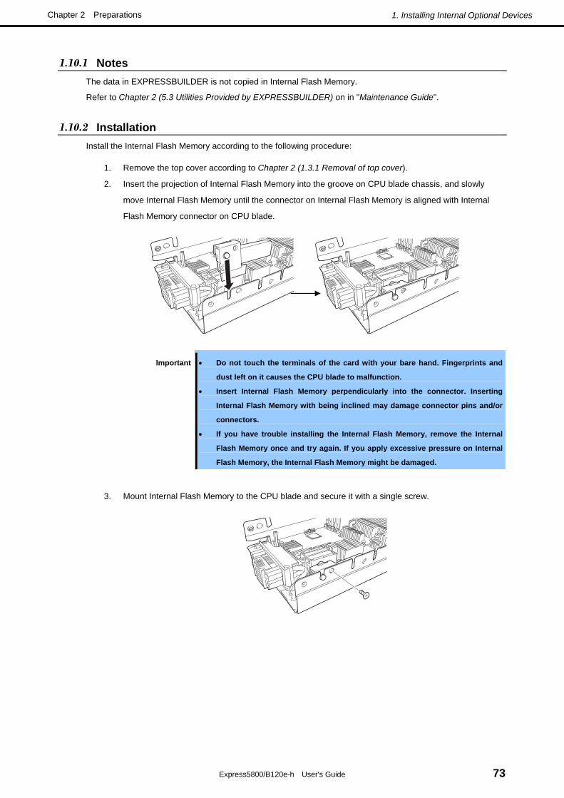
1. Installing Internal Optional Devices
Express5800/B120e-h User's Guide 73
Chapter 2 Preparations
1.10.1 Notes The data in EXPRESSBUILDER is not copied in Internal Flash Memory.
Refer to Chapter 2 (5.3 Utilities Provided by EXPRESSBUILDER) on in "Maintenance Guide".
1.10.2 Installation Install the Internal Flash Memory according to the following procedure:
1. Remove the top cover according to Chapter 2 (1.3.1 Removal of top cover).
2. Insert the projection of Internal Flash Memory into the groove on CPU blade chassis, and slowly
move Internal Flash Memory until the connector on Internal Flash Memory is aligned with Internal
Flash Memory connector on CPU blade.
Important • Do not touch the terminals of the card with your bare hand. Fingerprints and
dust left on it causes the CPU blade to malfunction.
• Insert Internal Flash Memory perpendicularly into the connector. Inserting
Internal Flash Memory with being inclined may damage connector pins and/or
connectors.
• If you have trouble installing the Internal Flash Memory, remove the Internal
Flash Memory once and try again. If you apply excessive pressure on Internal
Flash Memory, the Internal Flash Memory might be damaged.
3. Mount Internal Flash Memory to the CPU blade and secure it with a single screw.

1. Installing Internal Optional Devices
Express5800/B120e-h User's Guide 74
Chapter 2 Preparations
4. Mount the support bracket for Internal Flash Memory.
Align the positioning key with the groove, and secure it with two screws. (Two types of screws are
provided. Use the flat head screw for Internal Flash Memory, and the pan head screw for center side
of chassis.)
5. Install the component you have removed in earlier steps.
6. Install the CPU blade having been removed to the Blade Enclosure according to the User's Guide of
the Blade Enclosure.
7. Turn on the power of the CPU blade. Make sure that no error message appears in POST.
If any error messages are displayed, refer to Chapter 3 (1. POST Error Message) in "Maintenance
Guide".
1.10.3 Removal To remove the Internal Flash Memory, remove the top cover according to Chapter 2 (1.3.1 Removal of top cover), and then perform steps 2 and 3 of Chapter 2 (1.10.2 Installation) in reverse order.
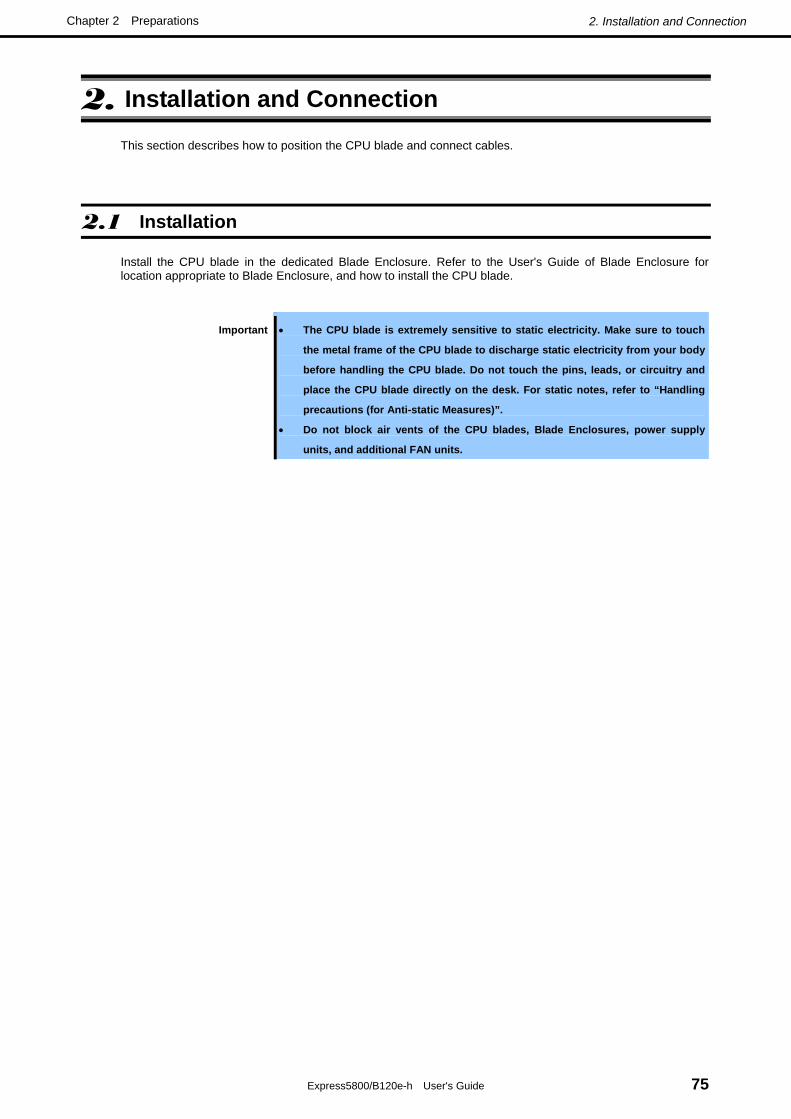
2. Installation and Connection
Express5800/B120e-h User's Guide 75
Chapter 2 Preparations
2. Installation and Connection
This section describes how to position the CPU blade and connect cables.
2.1 Installation
Install the CPU blade in the dedicated Blade Enclosure. Refer to the User's Guide of Blade Enclosure for location appropriate to Blade Enclosure, and how to install the CPU blade.
Important • The CPU blade is extremely sensitive to static electricity. Make sure to touch
the metal frame of the CPU blade to discharge static electricity from your body
before handling the CPU blade. Do not touch the pins, leads, or circuitry and
place the CPU blade directly on the desk. For static notes, refer to “Handling
precautions (for Anti-static Measures)”.
• Do not block air vents of the CPU blades, Blade Enclosures, power supply
units, and additional FAN units.

2. Installation and Connection
Express5800/B120e-h User's Guide 76
Chapter 2 Preparations
2.1.1 Checking MAC Address
Be sure to check the MAC addresses before installing a CPU blade in the Blade Enclosure.
A MAC address indicates the address specific for the network. It is expressed by 12-digit alphanumeric. MAC addresses are stored in LAN riser card which is a required option of CPU blade.
The number of MAC addresses stored in card depends on type of LAN riser card.
• Dual Port 1GBASE riser card kit(N8403-061F): 2
• Dual Port 10GBASE riser card kit(N8403-062F): 8
• Dual Port 10GBASE riser card kit(N8403-064F): 16
A MAC address is indicated in the area of LAN riser card as shown in the figure below.
The MAC address of LAN port is derived by adding the base value in the table below for the address.
For convenience, the added values of in the table below are quoted in decimal number. The MAC address is actually used, so will be shown in a hexadecimal number, please be careful.
Important f the NPAR feature is disabled, MAC addresses which can be used one (or two;
iSCSI offload type) will be per physical port. To derive the MAC address, please
refer to the PF0 of each physical port in the table below.
• Dual Port 1GBASE riser card kit(N8403-061F): LAN port number
Network MAC address
1 0 2 +2
• Dual Port 10GBASE riser card kit(N8403-062F): LAN port number
LAN port partition number (PF*) Network MAC address
0 0 1 +4 2 +8
1
3 +12 0 +2 1 +6 2 +10
2
3 +14
Label indicating MAC address
DG7xxx xxxxxxxxx XXXXXXXXXXXX
MAC address (12 characters)

2. Installation and Connection
Express5800/B120e-h User's Guide 77
Chapter 2 Preparations
• Dual Port 10GBASE riser card kit(N8403-064F): LAN port number
LAN port partition number (PF*)
Network MAC address iSCSI MAC address
0 0 +1 1 +4 +5 2 +8 +9
1
3 +12 +13 0 +2 +3 1 +6 +7 2 +10 +11
2
3 +14 +15
*PF : Physical Function
The MAC addresses can be checked from the proper Windows command.
• Windows
Enter "ipconfig /all" for the command prompt or from Run in the Start menu to see the indicated physical
address part.
• Linux
Enter "ifconfig" for prompt to see the indicated HWaddr.
• You may use the remote control feature of EXPRESSSCOPE Engine 3 (BMC) to check the MAC address.

2. Installation and Connection
Express5800/B120e-h User's Guide 78
Chapter 2 Preparations
2.2 Connecting Peripheral Devices
Connect peripheral devices to the CPU blade.
Tips Contact the maintenance engineer in your sales representative if you have any requests
on the system configuration including the connection to the uninterruptible power supply
system or auto power controller and the time schedule operation.
Important If you are installing the CPU blade in the Blade Enclosure (SIGMABLADE), follow
instructions described in the User's Guide of the Blade Enclosure.
WARNING
Be sure to observe the following precautions to use the server safety. Failure to observe the precautions may cause death or serious injury. For details, refer to Safety precautions in Precautions for Use.
• Do not hold the power plug with a wet hand.
• Do not connect earth lines to any gas tubes.
CAUTION
Be sure to observe the following precautions to use the server safely. Failure to observe the precautions may cause burns, injury, and property damage. For details, refer to Safety precautions in Precautions for Use.
• Do not plug the power cord in to an improper power source.
• Do not connect the power cord to an outlet that has an illegal number of connections.
• Insert the power plug into the outlet as far as it goes.
• Use the authorized power cord only.
• Do not connect or disconnect any interface cable with the power cord of the server plugged
to a power source.
• Do not use any unauthorized interface cable.

2. Installation and Connection
Express5800/B120e-h User's Guide 79
Chapter 2 Preparations
In the ordinary operation, SUV cables may not be connected to a CPU blade. Proper cable(s) should be connected to the USB, serial, and/or VGA ports on the CPU blade in the following cases:
• Using a Flash FDD with the server installed in the N8405-016F/016AF/016BF/016CF/040F/040AF Blade
Enclosure
• Performing maintenance work
• Updating BIOS and firmware
Use K410-150(00) SUV cable connector of CPU blade. (K410-150(00) SUV cable is a standard accessory for the Blade Enclosure (SIGMABLADE)).
Important • Do not use an external DVD-ROM drive connected via the K410-150(00) SUV
cable to install an operating system.
• Use the internal DVD-ROM drive of Blade Enclosure to install an operating
system.
The K410-150(00) SUV cable has the USB, serial interface, and monitor connectors at the ends. Connect a proper device at each of the ends. The shape of SUV cable may differ depending on shipment time, however, functionality does not change.
To CPU blade
To USB devices To monitor
To serial interface device
To serial interface device
To monitor
To USB devices (This connector has two ports.)
To CPU blade

2. Installation and Connection
Express5800/B120e-h User's Guide 80
Chapter 2 Preparations
Important • To connect a peripheral or interface cable provided by a vendor other than
NEC (or third party) to the CPU blade, make sure that the device is available for
the CPU blade. Some third party devices are not available for the CPU blade.
• The serial port connector cannot be directly connected with the leased line.
• Do not connect/disconnect the SUV cable or add/remove the USB device until
the operating system starts running.
To connect/disconnect the SUV cable or add/remove the USB device after OS
startup, follow restrictions of operating system.
If the device having serial interface is connected, first power off the CPU blade
and destination device, and remove the power cord from the destination device
before connecting/disconnecting SUV cable or serial cable. Failure to follow it
may cause the devices to be defected due to the potential difference between
them.
• The USB device may not work correctly in USB 2.0 High Speed mode
depending on type of USB device or cable length. In such a case, use a shorter
cable, or use a USB hub that supports USB2.0 High Speed mode.

2. Installation and Connection
Express5800/B120e-h User's Guide 81
Chapter 2 Preparations
2.2.1 USB Connection by K410-150(00) SUV Cable Connect an external DVD-ROM drive, keyboard, and mouse according to the figure shown below. Use the separately priced K410-150(00) SUV cable (or a standard accessory for the Blade Enclosure (SIGMABLADE).
However, when using a display unit, keyboard, and mouse connected to the Blade Enclosure by using the KVM selection feature of the Blade Enclosure, do not connect those devices by way of a SUV cable.
2.2.2 Connecting with Network The CPU blade is connected with network via the Blade Enclosure. Refer to the User's Guide of the Blade Enclosure for details.
Flash FDD
USB
USB
1
DMP
IDM
2
Display unit
Self-powered USB hub *
Mouse
* Use the USB hub and external DVD-ROM drive supported by this CPU blade.
External DVD-ROM drive *
Keyboard

2. Installation and Connection
Express5800/B120e-h User's Guide 82
Chapter 2 Preparations
2.2.3 Connecting with UPS To connect the power cord from the Blade Enclosure to an interruptive power supply (UPS), use outlet socket on the rear of the UPS. Refer to the manual that comes with the UPS for details.
When the power cord from the Blade Enclosure is connected to a UPS, you may need to change the BIOS SETUP of the CPU blade to link with power supply from the UPS.
Run BIOS SETUP, and select Server → AC-LINK and change parameter appropriately. Select Power On for automatic operation via UPS. For more information, refer to Chapter 2 (1.2.4 Server) in Maintenance Guide.
Option slot
Computer interface port (USB)
Reset button for overload prevention
Outlet socket
Input connector (NEMA5-15P)
Voltage sensitivity setting button
Computer interface port (COM)
Connector for TVSS device
<Example>

Express5800/B120e-h User's Guide 83
NEC Express5800 Series Express5800/B120e-h
Setup
This chapter describes how to set up the CPU blade.
1. Turning on the Server
POST (Power-On Self-Test) is explained in this section.
2. System BIOS (Setup)
You can customize the BIOS settings by following the instructions in this section.
3. EXPRESSSCOPE Engine 3
EXPRESSSCOPE Engine 3 provides useful features through the Baseboard Management Controller
(BMC).
4. EXPRESSBUILDER
EXPRESSBUILDER helps you to install Windows and maintain the server.
5. Installing Software Components
You can install Windows and bundled software by following the instructions in "Installation Guide
(Windows)".
6. Device Identification
Describes ID lamp provided in the server.
7. Power-off of Blade Server
Turn off power when not using the server.

1. Power-on of Blade Server
Express5800/B120e-h User's Guide 84
Chapter 3 Setup
1. Power-on of Blade Server
There are the following three ways to turn on the power of the CPU blade. Turn on the power of the CPU blade in any of the three ways after turning on the powers of the display unit and peripherals connected to the CPU blade.
Important Perform the power-on operation of the CPU blade by either the use of the POWER
switch or the remote power-on after the period of 60 seconds or longer has passed
from the supply of AC power to every power unit (POWER lamp on CPU blade is lit
amber). The power-on operation within the period of 60 seconds from the supply of
AC power to every power unit may not turn on the power of the CPU blade. If so,
turn on the power of the CPU blade by using the POWER switch after making sure
that the AC power is supplied to every power unit.
Note If a power cord on the Blade Enclosure is connected to a power controller including an
uninterruptible power supply (UPS), make sure that the power of the power controller is
turned on.
Tips When the power is supplied to the CPU blade, the initial diagnosis is executed for about
60 seconds. In this period, the POWER switch is disabled. Power on the CPU blade about
60 seconds immediately after you installed the CPU blade or turned on the power.

1. Power-on of Blade Server
Express5800/B120e-h User's Guide 85
Chapter 3 Setup
1.1 Power ON from CPU Blade
Press the POWER switch on the panel of the CPU blade (the POWER lamp on the CPU blade goes on green).
1
DMP
RST
2
ID
POWER lamp
POWER switch

1. Power-on of Blade Server
Express5800/B120e-h User's Guide 86
Chapter 3 Setup
1.2 Power ON from Network Serial Port
Depending on the BIOS setting of the CPU blade, the power of the CPU blade may be automatically turned on by a proper packet received from the network or via the modem connected to the serial port.
This power-on procedure can be specified by setting Wake On Events of System Hardware in the BIOS SETUP Utility.
1.3 Power ON from Remote Console
The power of the CPU blade can be turned on by using remote control feature of EXPRESSSCOPE Engine 3 (BMC).
1.4 Operation after Power ON
If the CPU blade is connected with a display unit, the NEC logo appears on the screen of the display unit after a while from the power-on.
Important Do not power off the server until NEC logo and some message appears.
While the NEC logo appears, the CPU blade runs the self-diagnosis program (POST) to diagnose the CPU blade itself. Refer to Chapter 3 (1.5 POST).

1. Power-on of Blade Server
Express5800/B120e-h User's Guide 87
Chapter 3 Setup
1.5 POST
POST (Power On Self-Test) is the self-diagnostic program stored in the CPU blade.
When you power on the CPU blade, the system automatically runs POST to check the motherboard, memory module, processor (CPU), keyboard, and mouse. POST also displays the start-up message of utilities, while in progress.
Usually, you do not need to check the contents of POST. However, check messages displayed at POST in the following cases.
• When you use the CPU blade for the first time.
• When the CPU blade appears to fail.
• When any error message is displayed
1.5.1 POST Execution Flow The following describes the progress of POST in the chronological order.
Important • Do not make unnecessary key entries or perform mouse operations while
POST is in progress.
• Some system configurations may display the message "Press Any Key" to
prompt a key entry. This message is driven by BIOS of an installed optional
board. Make sure to read the manual that comes with the optional board before
any key entry.
• Powering on the server, after you installed or removed an optional mezzanine
card, may display the message that indicates incorrect board configuration
and suspend POST.
In such a case, press the <F1> key to continue POST. Board configuration can
be made using the utility described later.
1. When the server is turned on, POST starts running, and displays messages indicating initialization of
memory and PCI devices. After messages are displayed, the LOGO appears.
Note • The keyboard becomes available after the logo is displayed.
• The screen may be switched to black (nothing is displayed) several times while the
initialization message is being displayed, however, it is not the problem.
• The initialization message may not appear depending on setting of BIOS SETUP, or
when optional VGA controller is connected.
• The initialization message does not appear on Console Redirection screen of serial
port.

1. Power-on of Blade Server
Express5800/B120e-h User's Guide 88
Chapter 3 Setup
2. If the <Esc> key is pressed, the logo disappears and the details of POST are displayed.
Tips You can set it to show the details of POST to be displayed from BIOS menu without
requiring the <ESC> key to be pressed. From the System BIOS Setup, set Quiet Boot to
Disabled in the Boot menu.
3. POST displays several types of message. These messages let you know that the installed CPU or
connected keyboard and mouse are detected.
Tips Depending on the installed PCI card configuration, the memory capacity might be
displayed less than actually installed physical memory. (This applies to the display of
BIOS Setup utility or OS system information.)
4. After a while, POST displays the following message.
Press <F2> SETUP, <F3> Internal flash memory, <F4> ROM Utility, <F12> Network
By pressing the designated function key following messages, you can call the functions below upon
completion of POST.
<F2> key: Run BIOS Setup Utility (SETUP). For information on the SETUP, refer to Chapter 3 (2
BIOS Setup Utility (SETUP).).
<F3> key: Run EXPRESSBUILDER from Internal Flash Memory (optional). For information on
EXPRESSBUILDER, refer to Chapter 3 (4. EXPRESSBUILDER).
<F4> key: Run the offline tool. For information on the offline tool, refer to Chapter 1 Maintenance
(9. Offline Tools) in "Maintenance Guide".
<F12> key: Boot from network.
Note • If the optional Internal Flash Memory is not installed in the system, the <F3> key
message will not be displayed.
• The <F3> key must be pressed within 5 seconds of the message being displayed.
• Note that the server will not boot from the Internal Flash Memory even if it is specified
to do so by pressing the <F3> key, as long as a bootable CD/DVD-ROM is set on the
drive with the boot priority of CD/DVD-ROM is set to higher than Solid State Drive.
5. If a controller which has its dedicated BIOS such as a SCSI controller board is installed, a message
that prompts you to start the dedicated utility to set each board is displayed.

1. Power-on of Blade Server
Express5800/B120e-h User's Guide 89
Chapter 3 Setup
Important • To start a dedicated utility for the RAID controller and so on when POST is
running, do as follows.
1. Make sure that you do not press any key before beginning this work.
2. Press a "Modifier Key" (such as <Ctrl> key) first, and hold down the
"Modifier Key" and press a “Character key” (such as <H> key) with the
"Modifier Key" pressed repeatedly until the dedicated utility starts.
• If you have failed to start the dedicated utility, please restart the server and
rerun POST to try again.
Example: SCSI BIOS Setup utility
Press <Ctrl> <A> for SCSISelect(TM) Utility!
The utility starts by pressing the <Ctrl> + <A> keys.
Example: If the jumper setting for an on-board RAID Controller is enabled
Press <Ctrl> <M> to Run LSI Software RAID Configuration Utility
The utility starts by pressing the <Ctrl> + <M> keys.
For details on the utility, refer to the manual supplied with each optional board.
Depending on the configuration, the message "Press Any Key" might appear to prompt a key entry. This is a
behavior of the BIOS of the optional board. Continue to operate after checking the manual of the optional board.
6. If you have set the password using the BIOS SETUP utility, the password entry screen appears upon
successful completion of POST.
Up to three password entries will be accepted. Three incorrect password entries disable the system
to boot. In such a case, turn off the power and wait about 10 seconds before turning on to boot the
CPU blade.
Important Do not set a password before installing an OS.
7. The OS starts when POST completes.
1.5.2 POST Error Messages When POST detects an error, it displays an error message on the screen. For descriptions of error messages, causes, and countermeasures, refer to "Maintenance Guide".
Important Take notes on the messages displayed before consulting with your maintenance
service company. Alarm messages are useful information for maintenance.

2. BIOS Setup Utility (SETUP)
Express5800/B120e-h User's Guide 90
Chapter 3 Setup
2. BIOS Setup Utility (SETUP)
This section describes how to configure Basic Input Output System (BIOS).
Before you install the server and add or remove optional devices, make sure you have read and understood this section to configure properly.
2.1 Overview
BIOS Setup Utility (SETUP) is a utility to do basic hardware settings. This utility is installed in a flash memory in the server as standard and can be run without requiring a media for boot.
BIOS settings were configured with optimal settings before the server was shipped to you. Therefore, in most of cases, you should not need to use the SETUP.
2.2 Starting and Exiting SETUP Utility
Starting SETUP Utility
Run POST following Chapter 3 (1.5.1 POST Execution Flow).
After a while, the following message will be displayed on the lower left of the screen.
Press <F2> SETUP, <F3> Internal Flash Memory, <F4> ROM Utility, <F12> Network
If you press <F2> key at this time, SETUP runs and displays Main menu upon completion of POST. (You can also press <F2> key while NEC logo appears to display Main menu.)
Tips If the password has been set, you will be prompted to enter the password at
the next startup of SETUP. (The timing when prompt message appears
depends on password setting.)
Up to three password entries will be accepted. If you fail to enter the
password correctly for three consecutive times, the server halts. (You can
no longer proceed.) Power off the server.
Exiting SETUP Utility
To save changes, select Save changes and Exit in Save & Exit menu. To discard changes, select Discard changes and Exit in Save & Exit menu.
Tips To restore the default setting, select Load Setup Defaults in Save & Exit
menu. (The default setting may differ from that of shipping defaults.)

2. BIOS Setup Utility (SETUP)
Express5800/B120e-h User's Guide 91
Chapter 3 Setup
2.3 Description on On-Screen Items and Key Usage
This section shows display examples and how to control the key. Use the keyboard to work with the
SETUP utility.
Cursor keys (<↑>, <↓>) Select an item displayed on the screen. If characters of an item are highlighted, that means the item is currently selected.
Cursor keys (<←>, <→>) Select top menus including Main, Advanced, Security, Server, Boot, and Save & Exit.
<−> key/<+> key Change the value (parameter) of the selected item. You cannot use this key when a menu which has on the left is selected.
<Enter> key Press this key to confirm the selected parameter.
<Esc> key Press this key to cancel pop up menu. In sub menu, press this key takes you to the previous screen. In top menu, press this key takes the following window is displayed. If you select Yes, the SETUP closes without saving the changed parameters.
Quit without saving?
[Yes] No
<F1> key
Press this key to display help information of key usage. If you need help using the SETUP, press this key. Press the <Esc> key to go back to the original screen.
Indicates the currently displayed menu
Help
Parameters (highlighted when selected*) *: Items that cannot be specified are dimmed.
Setting items
Indicates the menu has submenus.

2. BIOS Setup Utility (SETUP)
Express5800/B120e-h User's Guide 92
Chapter 3 Setup
<F2> key If you press this key, the following window appears. If you select Yes, the previous parameter(s) are restored. However if you save parameter(s) using [Save Changes], the saved parameter(s) are restored.
Load Previous Values?
[Yes] No
<F3> key
If you press this key, the following window appears. If you select Yes, restore the SETUP parameters of the currently selected item to the default setting. (This might be different from the parameters configured before shipment.)
Load Setup Defaults?
[Yes] No
<F4> key
If you press this key, the following window appears. If you select Yes, the parameter you configured is saved and SETUP closes.
Save configuration and exit?
[Yes] No

2. BIOS Setup Utility (SETUP)
Express5800/B120e-h User's Guide 93
Chapter 3 Setup
2.4 Cases that Require Configuration
Only if a case applies to any of following cases, use the SETUP utility to change a parameter which was configured as factory setting. Other than cases described below, do not change the settings. A list of SETUP parameters and factory settings are described in Chapter 2 (1. System BIOS) in "Maintenance Guide".
Category Description To be changed Remark
Change date and time Main → System Date
Main → System Time
Configurable on OS
On/Off NumLock on power ON Boot → Bootup Numlock State
Basic
On/Off the function to display
the NEC logo during POST
Boot → Quite Boot → Disabled Pressing the <Esc> key can
hide the logo.
Optional
board
Install RAID Controller board Advanced → PCI Configuration → PCI
Slot n Option ROM → Enabled
n is PCI slot number of the
RAID Controller
Change the boot order of
devices
Boot → Boot Option Priorities →
Change the boot priority
Use remote power on function
(from modem)
Advanced → Advanced Chipset
Configuration → Wake On Ring →
Enabled
Use remote power on function
(from RTC alarm)
Advanced → Advanced Chipset
Configuration → Wake On RTC Alarm
→ Enabled
Boot
Control from HW console
terminal
Advanced → Serial Port
Configuration → Change respective
setting.
Security Set a password Security → Administrator Password
→ Enter a password
(Set a password for Administrator first
and then User)
There are two types of
password; Administrator and
User.
Settings for User password
is limited compared to for
Administrator.
When the server is supplied
with power from UPS, always
turn on the power.
Server → AC-LINK → Power On
If the server is turned off by
using POWER switch, leave it
OFF even when UPS supplies
power.
Server → AC-LINK → Last State
UPS
Powerlink
Keep the power OFF even
when UPS supplies power.
Server → AC-LINK → Stay off

2. BIOS Setup Utility (SETUP)
Express5800/B120e-h User's Guide 94
Chapter 3 Setup
Password
If you have set a password, a message prompt you to enter password will be displayed from the next time.
Enter password [ ]
You can attempt password entry up to 3 times. If you entered a wrong password 3 times, operation
stops. (You cannot operate further.) Turn off the power.
Saving changes
If you finish configuration, select Save & Exit and then Save Changes and Exit to save changes and exit.
If you wish to exit without saving the changed parameters, select Save & Exit and then Discard Changes
and Exit.
Or if you wish to restore the setting to default values, select Save & Exit and then Load Setup Defaults.
(The default value might be different from the factory setting.)

3. EXPRESSSCOPE ENGINE 3
Express5800/B120e-h User's Guide 95
Chapter 3 Setup
3. EXPRESSSCOPE ENGINE 3
3.1 Overview
EXPRESSSCOPE Engine 3 provides a variety of features using BMC (Baseboard Management Controller), which is a system management LSI.
EXPRESSSCOPE Engine 3 monitors the temperature and voltage of the server. If you have the management LAN port connected to the network, you can remotely perform the following over a web browser or SSH client:
• Manage the server
• Remotely control the keyboard, video, and mouse (KVM)*
• Remotely access a CD/DVD/floppy disk/ISO image/USB memory*.
* To actualize these functions, virtual USB mass storage device (Remote FD, Remote CD/DVD, Remote USB Memory, or Vritual Flash) is always connected as USB mass storage devices for CPU blade.
Tips More than one removable drives other than the actual drive are displayed on the
operating system of the host system. This is a normal operation and these added
removable drives are the virtual removable drives reserved for the remote media
function of EXPRESSSCOPE Engine 3 (*1).
Fig. 1 Exp. Windows Server 2008 R2 Computer Folder (*2)
Fig. 2 Exp. Windows Server 2008 R2 Server Manager (*2)
*1 A function to use FD/CD/DVD drives, ISO images and USB memories
connected to the management PC as drives virtually connected to the host system.
*2 The number of drives and the drive letter are different depending on system configurations.

3. EXPRESSSCOPE ENGINE 3
Express5800/B120e-h User's Guide 96
Chapter 3 Setup
3.2 EXPRESSSCOPE ENGINE 3 Network Configuration
The network configuration of management LAN of EXPRESSSCOPE Engine 3 is obtained automatically from the Enclosure Manager which has DHCP server function. For detailed information on DHCP server of EM card, refer to EM Card User's Guide or Blade Enclosure User's Guide. By the factory default, DHCP is set to Enabled.
If DHCP is set to Disabled and you want to use the management LAN of EXPRESSSCOPE Engine 3, follow steps below to configure the network.
1. Run POST following Chapter 3 (1.5.1 POST Execution Flow). Wait until the following message
appears on the lower left of the screen.
Press <F2> SETUP, <F3> Internal flash memory, <F4> ROM Utility, <F12> Network
2. If you press the <F4> key at this time, ROM utility starts upon completion of POST.
You can also press the <F4> key while the NEC logo is being displayed to open the Off-line TOOL
MENU screen.
3. The keyboard selection screen appears. Select your keyboard type.
After that, the Off-line TOOL MENU screen appears. On this screen, specify the network settings for
EXPRESSSCOPE Engine 3.

3. EXPRESSSCOPE ENGINE 3
Express5800/B120e-h User's Guide 97
Chapter 3 Setup
4. When the Off-line TOOL MENU appears, select BMC Configuration, BMC Configuration, Network,
and then Property.
5. If Property is selected, the following screen is displayed. On this screen, specify whether to use
DHCP and if DHCP is not used, configure IP Address/Subnet Mask.
6. It will be available for use if you access EXPRESSSCOPE Engine 3 via Web browser of
management PC according to the setting.

4. EXPRESSBUILDER
Express5800/B120e-h User's Guide 98
Chapter 3 Setup
4. EXPRESSBUILDER
EXPRESSBUILDER helps you to install Windows or maintain the server.
4.1 Features of EXPRESSBUILDER
EXPRESSBUILDER provides the following features.
Features Descriptions Setup
(Windows reinstallation) Installs Windows on your server. Easily completes the process from RAID
configuration to installation of applications. To use this feature, select OS
installation in the menu after boot.
Bundled software* Stores various bundled software (such as NEC ESMPRO Agent).
Maintenance Diagnoses your server system. To use this feature, select Tool menu in the menu
after boot.
Documents* Stores documents including Instruction Manual of the server.
* Documents and some software components are not stored in Internal Flash Memory.
4.2 Starting EXPRESSBUILDER
If you want to configure RAID System or install Windows, start EXPRESSBUILDER by using any of the following.
EXPRESSBUILDER DVD:
Set the DVD on the drive and either turn on the server or restart the server by pressing <Ctrl> + <Alt>
+ <Delete> keys. EXPRESSBUILDER is booted from DVD.
If you want to install any bundled software or see documents, set the DVD to a computer running
Windows. Autorun menu appears automatically.
Internal Flash Memory (option):
Press <F3> key during POST. When using this option, make sure that the media was removed
from the drive.

5. Installing Software Components
Express5800/B120e-h User's Guide 99
Chapter 3 Setup
5. Installing Software Components
Continue to install software components such as OS.
Refer to the instructions below.
• Installation Guide (Windows)
Tips If you are using Red Hat Enterprise Linux 6, see (5.1 Notes on using Red Hat Enterprise
Linux 6).
5.1 Notes on using Red Hat Enterprise Linux 6
5.1.1 About the message caused by power consumption control in Red Hat Enterprise Linux 6
The following messages may be logged to “syslog”, but these do not indicate that failures have occurred in the server.
These messages indicate that the power consumption of a CPU blade has reached the upper limit value for ceiling control.
The power consumption in the entire system is controlled by the EM card installed in the blade enclosure, and the EM card controls the upper limit values of the CPU blades for ceiling control dynamically according to the power consumption of each CPU blade.
When the power consumption of a CPU blade has reached the upper limit value, the value is changed automatically by optimally allocating the power across the CPU blades, therefore, there will be no impact in the operation.
Please refer to the user's guide of the EM card for setting the power consumption control on the EM card.
■ Sample Message 1
kernel: CPU6: Core power limit notification (total events = 196670)
kernel: CPU21: Package power limit notification (total events = 196453)
kernel: CPU17: Core power limit normal
kernel: CPU23: Package power limit normal
mcelog: Processor 3 below trip temperature. Throttling disabled
These messages will be logged as many times as the number of logical CPU.
■ Sample Message 2
[Hardware Error]: Machine check events logged
You can distinguish between the messages for failures and for power capping by checking the Machine Check Events (MCE) logs (in /var/log/mcelog).
If a message that is similar to the following and that contains "THERMAL EVENT" is repeatedly logged in 8 lines in /var/log/mcelog at around the time (within 5 minutes) when the message containing "Hardware Error" is

5. Installing Software Components
Express5800/B120e-h User's Guide 100
Chapter 3 Setup
logged in /var/log/messages, the "Hardware Error" is logged by the OS when the OS receives a request to perform the power cutting operation, which does not indicate an failure in the server.
Ex.)
MCE 0
CPU 23 THERMAL EVENT TSC 3559f8b98fe2
TIME 1331221119 Fri Mar 9 00:38:39 2012
Processor 23 below trip temperature. Throttling disabled
STATUS 40000000882e0800 MCGSTATUS 0
MCGCAP 1000c14 APICID f SOCKETID 0
CPUID Vendor Intel Family 6 Model 45
Hardware event. This is not a software error.
It's possible to be to change the power control mode of this product to "Static mode" from "Dynamic mode" of default and reduce the output frequency of the message.
The power control mode is established in the EM card.
■ In the case of SIGMABLADE-M(N8405-016F/016AF/016BF)
See the section of "Using Command Line Console Feature" - "Command Reference" - "srvpwrmode" in the User's Guide of the EM card.
■ In the case of SIGMABLADE-Hv2(N8405-040F/040AF)
See the section of "Using Command Line Console Feature" - "Command Specification" - "CPU blade management commands" - "Setting power control mode of CPU blade" and "Displaying power control mode of CPU blade" in the User's Guide of the EM card.

6. Device Identification
Express5800/B120e-h User's Guide 101
Chapter 3 Setup
6. Device Identification
To identify the device to be maintained among more than one device, ID lamp is used. The ID lamp is located on the CPU blade installed in the Blade Enclosure. The ID lamp allows you to identify the device subject to maintenance among more than one CPU blade installed in the Blade Enclosure.
The ID lamp on CPU blade can be made lit blue by proper software commands (NEC ESMPRO Manager) from the management PC on the network or by pressing the ID switch on the CPU blade.
You may use the remote control feature of EXPRESSSCOPE Engine 3 (BMC) to perform the same operation as using the ID switch on the CPU blade.
1
DMP
RST
2
ID
ID switch
ID lamp

7. Power-off of Blade Server
Express5800/B120e-h User's Guide 102
Chapter 3 Setup
7. Power-off of Blade Server
There are the following three ways to turn off the power of the CPU blade.
• Power-off by OS shutdown
• Power-off from CPU Blade
Press the POWER switch on the panel of the CPU blade
• Power-off from Remote Console
The power of the CPU blade can be turned off by using "OS Shutdown" in remote control feature of
EXPRESSSCOPE Engine 3 (BMC).
The POWER lamp on the CPU blade of which power was turned off goes on amber.
Tips To power-off from CPU blade or remote console, the OS must be set so that it starts
shutdown process when the POWER switch on the CPU blade is pressed.

Express5800/B120e-h User's Guide 103
NEC Express5800 Series Express5800/B120e-h
Appendix 1. Specifications
Describes the specifications of this server.
2. Interrupt Lines
Describes the interrupt lines assigned to this server.
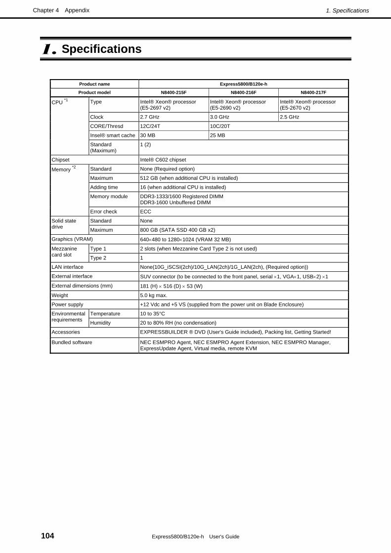
1. Specifications
Express5800/B120e-h User's Guide 104
Chapter 4 Appendix
1. Specifications
Product name Express5800/B120e-h
Product model N8400-215F N8400-216F N8400-217F
Type Intel® Xeon® processor (E5-2697 v2)
Intel® Xeon® processor (E5-2690 v2)
Intel® Xeon® processor (E5-2670 v2)
Clock 2.7 GHz 3.0 GHz 2.5 GHz
CORE/Thresd 12C/24T 10C/20T
Insel® smart cache 30 MB 25 MB
CPU *1
Standard (Maximum)
1 (2)
Chipset Intel® C602 chipset
Standard None (Required option)
Maximum 512 GB (when additional CPU is installed)
Adding time 16 (when additional CPU is installed)
Memory module DDR3-1333/1600 Registered DIMM DDR3-1600 Unbuffered DIMM
Memory *2
Error check ECC
Standard None Solid state drive Maximum 800 GB (SATA SSD 400 GB x2)
Graphics (VRAM) 640×480 to 1280×1024 (VRAM 32 MB)
Type 1 2 slots (when Mezzanine Card Type 2 is not used) Mezzanine card slot Type 2 1
LAN interface None(10G_iSCSI(2ch)/10G_LAN(2ch)/1G_LAN(2ch), (Required option))
External interface SUV connector (to be connected to the front panel, serial ×1, VGA×1, USB×2) ×1
External dimensions (mm) 181 (H) × 516 (D) × 53 (W)
Weight 5.0 kg max.
Power supply +12 Vdc and +5 VS (supplied from the power unit on Blade Enclosure)
Temperature 10 to 35°C Environmental requirements Humidity 20 to 80% RH (no condensation)
Accessories EXPRESSBUILDER ® DVD (User's Guide included), Packing list, Getting Started!
Bundled software NEC ESMPRO Agent, NEC ESMPRO Agent Extension, NEC ESMPRO Manager, ExpressUpdate Agent, Virtual media, remote KVM

1. Specifications
Express5800/B120e-h User's Guide 105
Chapter 4 Appendix
Product name Express5800/B120e-h
Product model N8400-218F N8400-219F N8400-220F
Type Intel® Xeon® processor (E5-2650L v2)
Intel® Xeon® processor (E5-2650 v2)
Intel® Xeon® processor (E5-2630 v2)
Clock 1.7 GHz 2.6 GHz 2.6 GHz
CORE/Thresd 10C/20T 8C/16T 6C/12T
Insel® smart cache 25 MB 20 MB 15 MB
CPU *1
Standard (Maximum)
1 (2)
Chipset Intel® C602 chipset
Standard None (Required option)
Maximum 512 GB (when additional CPU is installed)
Adding time 16 (when additional CPU is installed)
Memory module DDR3-1333/1600 Registered DIMM DDR3-1600 Unbuffered DIMM
Memory *2
Error check ECC
Standard None Solid state drive Maximum 800 GB (SATA SSD 400 GB x2)
Graphics (VRAM) 640×480 to 1280×1024 (VRAM 32 MB)
Type 1 2 slots (when Mezzanine Card Type 2 is not used) Mezzanine card slot Type 2 1
LAN interface None(10G_iSCSI(2ch)/10G_LAN(2ch)/1G_LAN(2ch), (Required option))
External interface SUV connector (to be connected to the front panel, serial ×1, VGA×1, USB×2) ×1
External dimensions (mm) 181 (H) × 516 (D) × 53 (W)
Weight 5.0 kg max.
Power supply +12 Vdc and +5 VS (supplied from the power unit on Blade Enclosure)
Temperature 10 to 35°C Environmental requirements Humidity 20 to 80% RH (no condensation)
Accessories EXPRESSBUILDER ® DVD (User's Guide included), Packing list, Getting Started!
Bundled software NEC ESMPRO Agent, NEC ESMPRO Agent Extension, NEC ESMPRO Manager, ExpressUpdate Agent, Virtual media, remote KVM

1. Specifications
Express5800/B120e-h User's Guide 106
Chapter 4 Appendix
*1. Maximum number of processor cores that the server supports The maximum number of processor cores available on this server depends on base architecture (x86 architecture) and specification of OS as shown below. Maximum number of processor cores
OS Maximum number of logical processors supported by OS
Maximum number of logical processors supported by this
server
Microsoft Windows Server 2008 Standard Microsoft Windows Server 2008 Enterprise
32 32
Microsoft Windows Server 2008 Standard (x64) Microsoft Windows Server 2008 Enterprise (x64)
64 48
Microsoft Windows Server 2008 R2 Standard (x64) Microsoft Windows Server 2008 R2 Enterprise (x64)
256 48
Microsoft Windows Server 2012 Standard Microsoft Windows Server 2012 Datacenter
640 (Maximum number of logical processors when using Hyper-V technology: 320)
48
Red Hat Enterprise Linux 5 (x86) Red Hat Enterprise Linux 6 (x86)
32 32
Red Hat Enterprise Linux 5 (EM64T) Red Hat Enterprise Linux 6 (x86_64)
160 48
VMware ESXi 5.0 / 5.1 160 48
*2. Maximum DIMM capacity that the server supports The maximum DIMM capacity available on this server depends on base architecture (x86 architecture) and specification of OS as shown below. Maximum DIMM capacity
OS Maximum DIMM capacity
supported by OS Maximum DIMM capacity supported by this server
4GB (when using HW-DEPfeature*) * Shipping default
Microsoft Windows Server 2008 Standard 4GB
Approx. 2GB (when not using HW-DEP feature*) * When [Disabled] is specified for
[Execute Disable Bit (XD Bit)] in BIOS.
Microsoft Windows Server 2008 Standard (x64) Microsoft Windows Server 2008 R2 Standard (x64)
32GB 32GB
Microsoft Windows Server 2008 Enterprise 64GB 64GB
Microsoft Windows Server 2008 Enterprise (x64) Microsoft Windows Server 2008 R2 Enterprise (x64)
2TB 512GB
Microsoft Windows Server 2012 Standard Microsoft Windows Server 2012 Datacenter
4TB (Maximum DIMM capacity on virtual machine: 1TB)
512GB
Red Hat Enterprise Linux 5 (x86) Red Hat Enterprise Linux 6 (x86)
16GB 16GB
Red Hat Enterprise Linux 5 (EM64T) 1TB 512GB
Red Hat Enterprise Linux 6 (x86_64) 3TB 512GB
VMware ESXi 5.0 / 5.1 2TB (Maximum DIMM capacity on virtual machine: 1TB)
512GB

2. Interrupt Lines
Express5800/B120e-h User's Guide 107
Chapter 4 Appendix
2. Interrupt Lines
Interrupt lines are assigned as factory settings as shown below. Use this table as a reference when you add optional devices.
● Interrupt lines
As factory settings, interrupt lines are assigned as follows.
IRQ Peripheral Device (Controller) IRQ Peripheral Device (Controller)
0 System timer 8 Real-time clock
1 − 9 Microsoft ACPI-Compliant System
2 Cascade connection 10 PCI
3 COM 2 serial port 11 PCI
4 COM 1 serial port 12 −
5 PCI 13 Arithmetic operation processor
6 − 14 Primary IDE
7 − 15 Secondary IDE