exploring the informal translation of omt object … · exploring the informal translation of omt...
TRANSCRIPT

Exploring the informal translation of OMT object models in
B
Fiona PolackDepartment of Computer Science
Univeristy of York, UK, +1904 432722 (fax +1904 432767)[email protected]
March 14, 2003
1 Introduction
This paper reports work carried out between 1997 and 2001. Although OMT is now rarely used,much of the work is directly applicable to UML class models. This work, and particularly theB machine structures, has influenced our subsequent work on a formally-underpinned version ofUML for information systems[10, 9, 18].
Various authors[4, 5, 11, 12, 23] have demonstrated that a state model using the OMT object mod-elling notation can be transcribed into B machines. However, they provide only small illustrativefragments of OMT diagrams.
In this paper, a model was chosen from the OMT book[22], and a B[1] specification developed.The transcription of the model into B machines is used to evaluate the specification work. Thepaper also draws analogies with work on the integration of non-object-oriented methods integrationwork, and makes tentative proposals for the non-formal validation of the equivalence of the tworepresentations produced.
The machines presented were developed using the BToolkit1. Most tool-generated proof obli-gations have been discharged using the tool’s provers. Some simple set theory was provided tocomplete some proofs. The machines have not been refined or implemented.
2 The OMT Model
The transcription uses the OMT case study, Computer Animation[22, chapter 19]. The originalOMT specification is for the OSCAR system, which produces 3-D computer-generated animatedfilm sequences based on the results of scientific experiments. The chapter comprises a detailedtext description of the animation process, a complete object model (16 classes, including sub-classes), simple (3-state) dynamic models of two classes, and one functional model (5 interactingsubprocesses).
This paper concentrates on part of the object model, as summarised in Figure 1. This representsthe scenes of the animation. Within a scene, control is provided (based on a script) through lists ofactions. An action is any valid statement in the animation language. The actions are grouped by
1The BToolkit is available from B-Core(UK) Ltd, http://www.b-core.com/
1

the director in to cues, which are active for a user-defined duration and specify the actions appliedto the objects in the animation. Each scene specifies a renderer to produce its frame images.
The object model comprises a complex hierarchical object, and its associations with two otherobjects. Its derivation is discussed in the chapter[22, pp420-422] The following description drawson the dynamic models and text detail of the Rumbaugh case study.
���
���
���
���
����
start action
end action
tick actionACTION
text
SEQUENCER
start time
end time
CUE
tick
SCENE
current time
time resolution
start
tick
RENDERER
time resolution
background colour
frame counter
viewport
render, expose
do lights, actors, cameras
renderer class, linking to rest of model
Figure 1: The OMT object model for the case study, after Rumbaugh et al[22], p422
The superclass SEQUENCER has attributes, starttime and endtime. SEQUENCER is an abstractclass (it has no objects of its own); it simply expresses the common characteristics of the SCENEand CUE subclasses.
The SCENE class is an aggregation of CUE . This implies that each CUE object exists only in thecontext of its linked SCENE . CUE and SCENE each have (separate) tick operations; SCENEalso has a start operation which initiated its ticking, and timing attributes (currentTime andtimeResolution).
When a CUE object’s startTime becomes later than its controlling SCENE object’s currentTime,the CUE object issues an event which causes its associated startactions to be performed. TheCUE then continues to perform its tickactions in sequence, until the SCENE ’s currentTime isafter the CUE ’s endTime. The relevant endactions are then performed, and the CUE becomesinactive.
The SCENE also has linked startactions, tickactions and endactions, triggered at its own startTime,tick and endTime. At each SCENE tick, the SCENE object’s operations trigger rendering events,calling the operations of associated RENDERER objects.
In the original Rumbaugh model, RENDERER is a superclass for two sub-classes (PHIGS andMOVIEBYU ), and is linked by aggregation to a range of other objects. These are not included
2
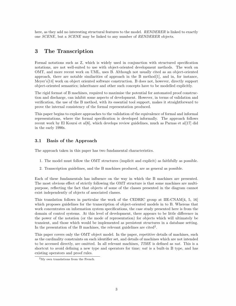
here, as they add no interesting structural features to the model. RENDERER is linked to exactlyone SCENE , but a SCENE may be linked to any number of RENDERER objects.
3 The Transcription
Formal notations such as Z, which is widely used in conjunction with structured specificationnotations, are not well-suited to use with object-oriented development methods. The work onOMT, and more recent work on UML, uses B. Although not usually cited as an object-orientedapproach, there are notable similarities of approach in the B method[1], and in, for instance,Meyer’s[14] work on object oriented software construction. B does not, however, directly supportobject-oriented semantics; inheritance and other such concepts have to be modelled explicitly.
The rigid format of B machines, required to maximise the potential for automated proof construc-tion and discharge, can inhibit some aspects of development. However, in terms of validation andverification, the use of the B method, with its essential tool support, makes it straightforward toprove the internal consistency of the formal representation produced.
This paper begins to explore approaches to the validation of the equivalence of formal and informalrepresentations, where the formal specification is developed informally. The approach followsrecent work by El Koursi et al[6], which develops review guidelines, much as Parnas et al[17] didin the early 1990s.
3.1 Basis of the Approach
The approach taken in this paper has two fundamental characteristics.
1. The model must follow the OMT structures (implicit and explicit) as faithfully as possible.
2. Transcription guidelines, and the B machines produced, are as general as possible.
Each of these fundamentals has influence on the way in which the B machines are presented.The most obvious effect of strictly following the OMT structure is that some machines are multi-purpose, reflecting the fact that objects of some of the classes presented in the diagram cannotexist independently of objects of associated classes.
This translation follows in particular the work of the CEDRIC group at IIE-CNAM[4, 5, 16]which proposes guidelines for the transcription of object-oriented models in to B. Whereas thatwork concentrates on information system specifications, the case study presented here is from thedomain of control systems. At this level of development, there appears to be little difference inthe power of the notation (or the mode of representation) for objects which will ultimately betransient, and those which would be implemented as persistent structures in a database setting.In the presentation of the B machines, the relevant guidelines are cited2.
This paper covers only the OMT object model. In the paper, repetitive details of machines, suchas the cardinality constraints on each identifier set, and details of machines which are not intendedto be accessed directly, are omitted. In all relevant machines, TIME is defined as nat . This is ashortcut to avoid defining a new type and operators for time; nat is a built-in B type, and hasexisting operators and proof rules.
2My own translations from the French.
3

4 B Generics
In writing any formal specification, it is useful to have a set of generics or templates for basiccomponents of the structured models. This approach is taken by the SAZ Method[20, 19]3, andmore recently in work on UML and Z[2]. The B method permits parameterisation and renaming ofcopies of machines, but it does not permit other machines to be used as parameters; renaming onlyapplies to variables and operations, not, for instance, sets and definitions. This style of replicationis not amenable to the widespread use of generics.
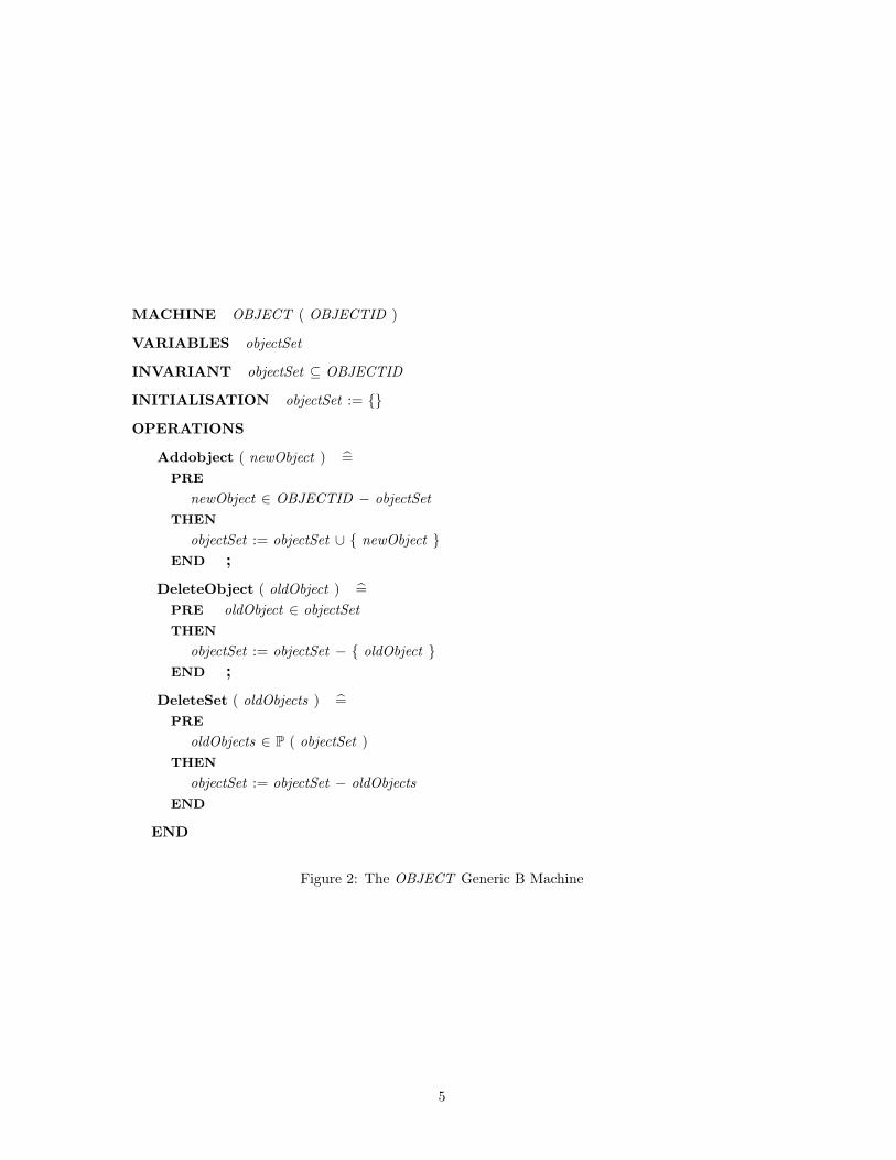
The B specification in this paper uses one generic machine, OBJECT (Figure 2). The genericmachine is used simply to provide uniformity. It ensures that all classes are defined according toa common format, and discourages ad hoc variation. The machine encapsulates the translationrule,
each entity e gives rise to (a) the set of (identifiers of) possible objects of e, givenset Se ; (b) the set of (identifiers of) existing objects of e, variable Ve [4, Rule S3].
The sets of things of interest in the system are represented in B by sets of existing object identifiers(object ⊆ OBJECTID). These are introduced as un-elaborated finite sets, thus maintaining theOMT assertion that objects are implicitly unique. It would be a breach of the spirit of object-orientation to instantiate the object identity with an attribute of the class.
The operations of this machine have no external interface; they simply add and delete a singleobject. The entity operation which takes an instance, defined in terms of its attribute values,as input, and assigns it an identifier, is not definable at this level, since the attributes of anyinstantiated object type will be different. However, an add operation is defined so that the includ-ing machines can increment the set of instances of their specific object. Two deletion operationsare defined; these delete a single instance and a set of instances, based on the identifiers of theinstances.
5 Specification of Independent Objects
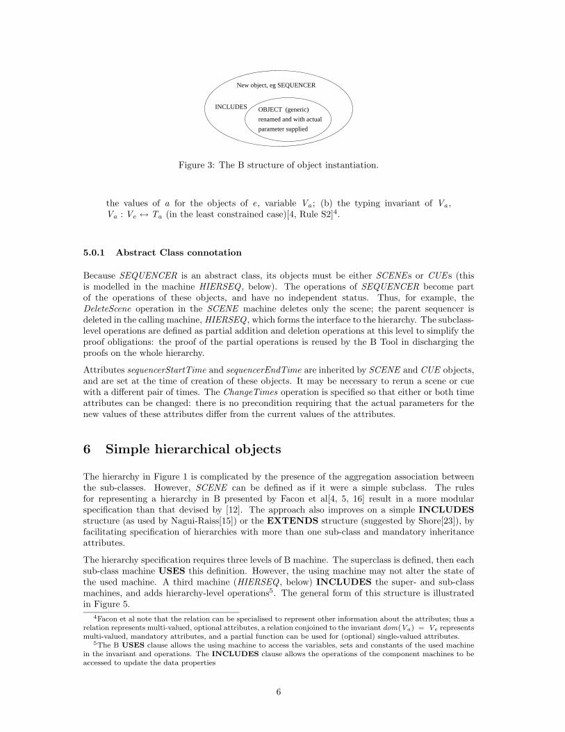
Any class whose objects can exist independently of association links can be defined by instanti-ating the OBJECT class, using the INCLUDES clause of a new machine, and adding the dataproperties specific to that object (Figure 3). The interface of the operations, and any additionalsemantics required, are also added.
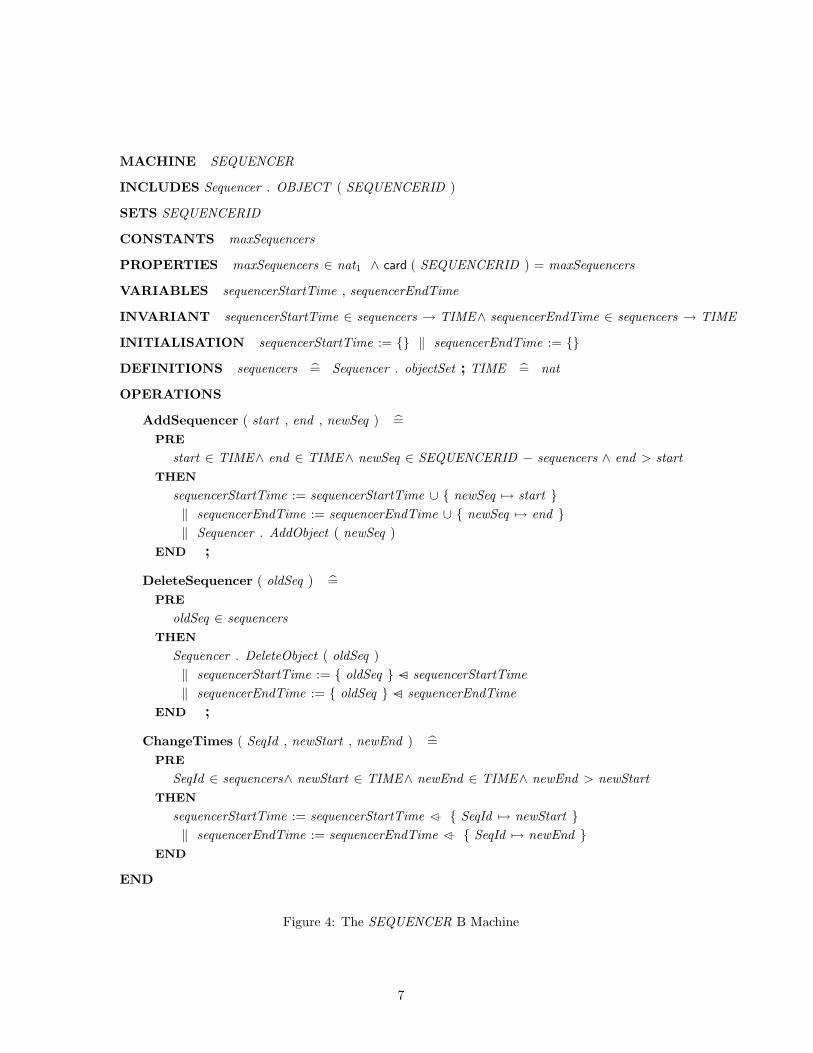
In the case study, there is only one class that can be treated as independent in this sense –SEQUENCER. Strictly, SEQUENCER is not able to exist in isolation, since it is the abstractsuperclass of the hierarchy, the objects of which can only exist as components of the sub-classobject instances. However, the initial specification of SEQUENCER can be performed withoutreference to other machines.
The instantiation (Figure 4) defines a set , SEQUENCERID , for identifiers. A constant, maxSequencersand a PROPERTIES clause constrain the size of the set, since infinite sets are not amenable toB proof. DEFINITIONS clauses are used to simplify some parts of the expressions.
Attributes are linked to classes using total functions from the set of objects (sequencers) to thetype of the attribute (in this case, both are of type, TIME ). This follows the translation rule,
each attribute a of type Ta , of the entity e, gives rise to (a) the relation defining3The early SAZ work, including the method document and several of the published papers, contain errors in the
formal specification; some of these are corrected in papers published after 1994[13, 21].
4
MACHINE OBJECT ( OBJECTID )
VARIABLES objectSet
INVARIANT objectSet ⊆ OBJECTID
INITIALISATION objectSet := {}
OPERATIONS
Addobject ( newObject ) =PRE
newObject ∈ OBJECTID − objectSetTHEN
objectSet := objectSet ∪ { newObject }END ;
DeleteObject ( oldObject ) =PRE oldObject ∈ objectSetTHEN
objectSet := objectSet − { oldObject }END ;
DeleteSet ( oldObjects ) =PRE
oldObjects ∈ P ( objectSet )THEN
objectSet := objectSet − oldObjectsEND
END
Figure 2: The OBJECT Generic B Machine
5
parameter supplied
renamed and with actual
OBJECT (generic)INCLUDES
New object, eg SEQUENCER
Figure 3: The B structure of object instantiation.
the values of a for the objects of e, variable Va ; (b) the typing invariant of Va ,Va : Ve ↔ Ta (in the least constrained case)[4, Rule S2]4.
5.0.1 Abstract Class connotation
Because SEQUENCER is an abstract class, its objects must be either SCENE s or CUE s (thisis modelled in the machine HIERSEQ , below). The operations of SEQUENCER become partof the operations of these objects, and have no independent status. Thus, for example, theDeleteScene operation in the SCENE machine deletes only the scene; the parent sequencer isdeleted in the calling machine, HIERSEQ , which forms the interface to the hierarchy. The subclass-level operations are defined as partial addition and deletion operations at this level to simplify theproof obligations: the proof of the partial operations is reused by the B Tool in discharging theproofs on the whole hierarchy.
Attributes sequencerStartTime and sequencerEndTime are inherited by SCENE and CUE objects,and are set at the time of creation of these objects. It may be necessary to rerun a scene or cuewith a different pair of times. The ChangeTimes operation is specified so that either or both timeattributes can be changed: there is no precondition requiring that the actual parameters for thenew values of these attributes differ from the current values of the attributes.
6 Simple hierarchical objects
The hierarchy in Figure 1 is complicated by the presence of the aggregation association betweenthe sub-classes. However, SCENE can be defined as if it were a simple subclass. The rulesfor representing a hierarchy in B presented by Facon et al[4, 5, 16] result in a more modularspecification than that devised by [12]. The approach also improves on a simple INCLUDESstructure (as used by Nagui-Raiss[15]) or the EXTENDS structure (suggested by Shore[23]), byfacilitating specification of hierarchies with more than one sub-class and mandatory inheritanceattributes.
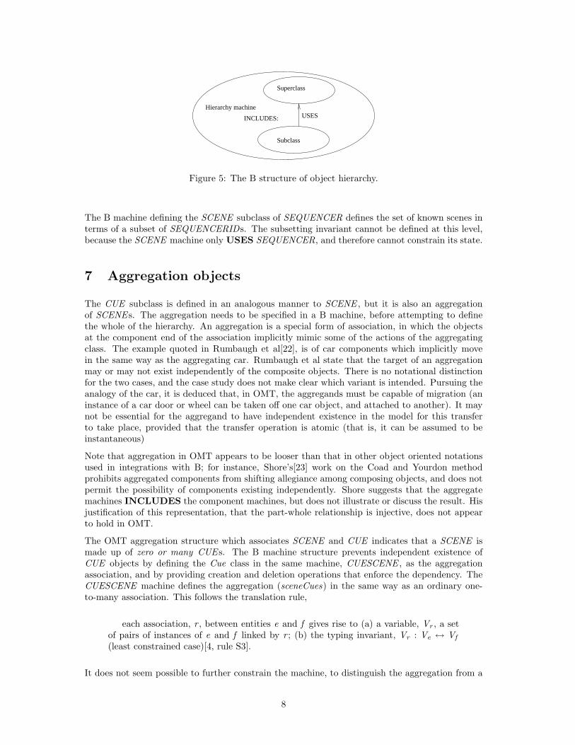
The hierarchy specification requires three levels of B machine. The superclass is defined, then eachsub-class machine USES this definition. However, the using machine may not alter the state ofthe used machine. A third machine (HIERSEQ , below) INCLUDES the super- and sub-classmachines, and adds hierarchy-level operations5. The general form of this structure is illustratedin Figure 5.
4Facon et al note that the relation can be specialised to represent other information about the attributes; thus arelation represents multi-valued, optional attributes, a relation conjoined to the invariant dom(Va ) = Ve representsmulti-valued, mandatory attributes, and a partial function can be used for (optional) single-valued attributes.
5The B USES clause allows the using machine to access the variables, sets and constants of the used machinein the invariant and operations. The INCLUDES clause allows the operations of the component machines to beaccessed to update the data properties
6
MACHINE SEQUENCER
INCLUDES Sequencer . OBJECT ( SEQUENCERID )
SETS SEQUENCERID
CONSTANTS maxSequencers
PROPERTIES maxSequencers ∈ nat1 ∧ card ( SEQUENCERID ) = maxSequencers
VARIABLES sequencerStartTime , sequencerEndTime
INVARIANT sequencerStartTime ∈ sequencers → TIME∧ sequencerEndTime ∈ sequencers → TIME
INITIALISATION sequencerStartTime := {} ‖ sequencerEndTime := {}
DEFINITIONS sequencers = Sequencer . objectSet ; TIME = nat
OPERATIONS
AddSequencer ( start , end , newSeq ) =PRE
start ∈ TIME∧ end ∈ TIME∧ newSeq ∈ SEQUENCERID − sequencers ∧ end > startTHEN
sequencerStartTime := sequencerStartTime ∪ { newSeq 7→ start }‖ sequencerEndTime := sequencerEndTime ∪ { newSeq 7→ end }‖ Sequencer . AddObject ( newSeq )
END ;
DeleteSequencer ( oldSeq ) =PRE
oldSeq ∈ sequencersTHEN
Sequencer . DeleteObject ( oldSeq )‖ sequencerStartTime := { oldSeq } −C sequencerStartTime‖ sequencerEndTime := { oldSeq } −C sequencerEndTime
END ;
ChangeTimes ( SeqId , newStart , newEnd ) =PRE
SeqId ∈ sequencers∧ newStart ∈ TIME∧ newEnd ∈ TIME∧ newEnd > newStartTHEN
sequencerStartTime := sequencerStartTime <+ { SeqId 7→ newStart }‖ sequencerEndTime := sequencerEndTime <+ { SeqId 7→ newEnd }
END
END
Figure 4: The SEQUENCER B Machine
7
USESINCLUDES:
Hierarchy machine
Superclass
Subclass
Figure 5: The B structure of object hierarchy.
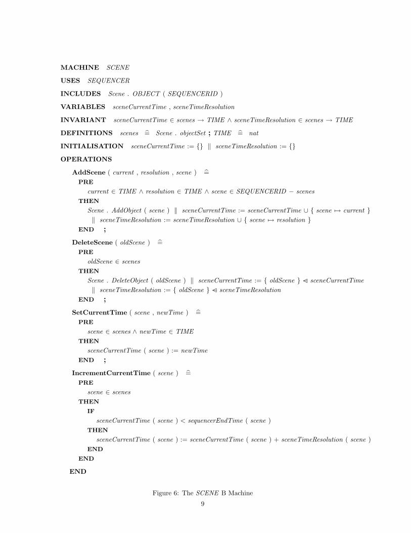
The B machine defining the SCENE subclass of SEQUENCER defines the set of known scenes interms of a subset of SEQUENCERIDs. The subsetting invariant cannot be defined at this level,because the SCENE machine only USES SEQUENCER, and therefore cannot constrain its state.
7 Aggregation objects
The CUE subclass is defined in an analogous manner to SCENE , but it is also an aggregationof SCENE s. The aggregation needs to be specified in a B machine, before attempting to definethe whole of the hierarchy. An aggregation is a special form of association, in which the objectsat the component end of the association implicitly mimic some of the actions of the aggregatingclass. The example quoted in Rumbaugh et al[22], is of car components which implicitly movein the same way as the aggregating car. Rumbaugh et al state that the target of an aggregationmay or may not exist independently of the composite objects. There is no notational distinctionfor the two cases, and the case study does not make clear which variant is intended. Pursuing theanalogy of the car, it is deduced that, in OMT, the aggregands must be capable of migration (aninstance of a car door or wheel can be taken off one car object, and attached to another). It maynot be essential for the aggregand to have independent existence in the model for this transferto take place, provided that the transfer operation is atomic (that is, it can be assumed to beinstantaneous)
Note that aggregation in OMT appears to be looser than that in other object oriented notationsused in integrations with B; for instance, Shore’s[23] work on the Coad and Yourdon methodprohibits aggregated components from shifting allegiance among composing objects, and does notpermit the possibility of components existing independently. Shore suggests that the aggregatemachines INCLUDES the component machines, but does not illustrate or discuss the result. Hisjustification of this representation, that the part-whole relationship is injective, does not appearto hold in OMT.
The OMT aggregation structure which associates SCENE and CUE indicates that a SCENE ismade up of zero or many CUE s. The B machine structure prevents independent existence ofCUE objects by defining the Cue class in the same machine, CUESCENE , as the aggregationassociation, and by providing creation and deletion operations that enforce the dependency. TheCUESCENE machine defines the aggregation (sceneCues) in the same way as an ordinary one-to-many association. This follows the translation rule,
each association, r , between entities e and f gives rise to (a) a variable, Vr , a setof pairs of instances of e and f linked by r ; (b) the typing invariant, Vr : Ve ↔ Vf
(least constrained case)[4, rule S3].
It does not seem possible to further constrain the machine, to distinguish the aggregation from a
8
MACHINE SCENE
USES SEQUENCER
INCLUDES Scene . OBJECT ( SEQUENCERID )
VARIABLES sceneCurrentTime , sceneTimeResolution
INVARIANT sceneCurrentTime ∈ scenes → TIME ∧ sceneTimeResolution ∈ scenes → TIME
DEFINITIONS scenes = Scene . objectSet ; TIME = nat
INITIALISATION sceneCurrentTime := {} ‖ sceneTimeResolution := {}
OPERATIONS
AddScene ( current , resolution , scene ) =PRE
current ∈ TIME ∧ resolution ∈ TIME ∧ scene ∈ SEQUENCERID − scenesTHEN
Scene . AddObject ( scene ) ‖ sceneCurrentTime := sceneCurrentTime ∪ { scene 7→ current }‖ sceneTimeResolution := sceneTimeResolution ∪ { scene 7→ resolution }
END ;
DeleteScene ( oldScene ) =PRE
oldScene ∈ scenesTHEN
Scene . DeleteObject ( oldScene ) ‖ sceneCurrentTime := { oldScene } −C sceneCurrentTime‖ sceneTimeResolution := { oldScene } −C sceneTimeResolution
END ;
SetCurrentTime ( scene , newTime ) =PRE
scene ∈ scenes ∧ newTime ∈ TIMETHEN
sceneCurrentTime ( scene ) := newTimeEND ;
IncrementCurrentTime ( scene ) =PRE
scene ∈ scenesTHEN
IF
sceneCurrentTime ( scene ) < sequencerEndTime ( scene )THEN
sceneCurrentTime ( scene ) := sceneCurrentTime ( scene ) + sceneTimeResolution ( scene )END
END
END
Figure 6: The SCENE B Machine
9
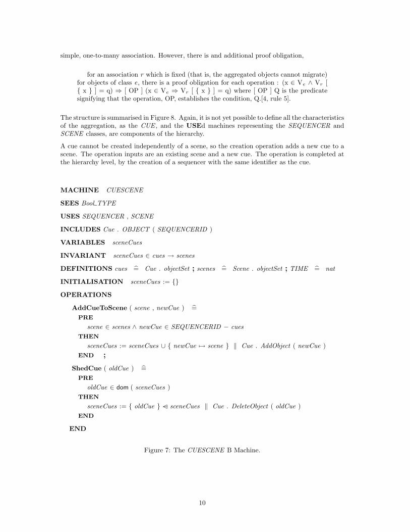
simple, one-to-many association. However, there is and additional proof obligation,
for an association r which is fixed (that is, the aggregated objects cannot migrate)for objects of class e, there is a proof obligation for each operation : (x ∈ Ve ∧ Vr [{ x } ] = q) ⇒ [ OP ] (x ∈ Ve ⇒ Vr [ { x } ] = q) where [ OP ] Q is the predicatesignifying that the operation, OP, establishes the condition, Q.[4, rule 5].
The structure is summarised in Figure 8. Again, it is not yet possible to define all the characteristicsof the aggregation, as the CUE , and the USEd machines representing the SEQUENCER andSCENE classes, are components of the hierarchy.
A cue cannot be created independently of a scene, so the creation operation adds a new cue to ascene. The operation inputs are an existing scene and a new cue. The operation is completed atthe hierarchy level, by the creation of a sequencer with the same identifier as the cue.
MACHINE CUESCENE
SEES Bool TYPE
USES SEQUENCER , SCENE
INCLUDES Cue . OBJECT ( SEQUENCERID )
VARIABLES sceneCues
INVARIANT sceneCues ∈ cues → scenes
DEFINITIONS cues = Cue . objectSet ; scenes = Scene . objectSet ; TIME = nat
INITIALISATION sceneCues := {}
OPERATIONS
AddCueToScene ( scene , newCue ) =PRE
scene ∈ scenes ∧ newCue ∈ SEQUENCERID − cuesTHEN
sceneCues := sceneCues ∪ { newCue 7→ scene } ‖ Cue . AddObject ( newCue )END ;
ShedCue ( oldCue ) =PRE
oldCue ∈ dom ( sceneCues )THEN
sceneCues := { oldCue } −C sceneCues ‖ Cue . DeleteObject ( oldCue )END
END
Figure 7: The CUESCENE B Machine.
10

object (Scene)Independent
objects in the association)(super class of both
(Sequencer)
USESUSES
(Cue)
of dependent objectGeneric instantiation
Association machine (CueScene)
INCLUDES:
Figure 8: The B structure of an aggregation association with a dependent object.
8 The whole hierarchy
The full representation of the hierarchy defines constraints and operations at the hierarchy level.The state part of the hierarchy-level machine HIERSEQ (Figure 9) INCLUDES the machinesdefining the superclass (SEQUENCER) and the two subclass (SCENE and CUESCENE ). HIERSEQalso provides the top-level operations and constraints on the way that CUE objects are aggregatedinto SCENE s. HIERSEQ can use each included machine’s operations to amend that machine’sstate.
The invariant defines the fact that the set of known SEQUENCERIDs is partitioned betweenSCENE s and CUE s. This follows the translation rule,
for each sub-class, e, of class, f , (a) the given set (possible instances) for e is thesame as that for f ; (b) there is an additional invariant, Ve ⊆ Vf [4, Rule S9]6.
MACHINE HIERSEQ
SEES Bool TYPE
INCLUDES CUESCENE , SCENE , SEQUENCER
DEFINITIONS sequencers = Sequencer . objectSet ; cues = Cue . objectSet ;scenes = Scene . objectSet ; TIME = nat
INVARIANT sequencers = scenes ∪ cues ∧ scenes ∩ cues = {}
Figure 9: The state components of the HIERSEQ Machine for the Sequencer Hierarchy
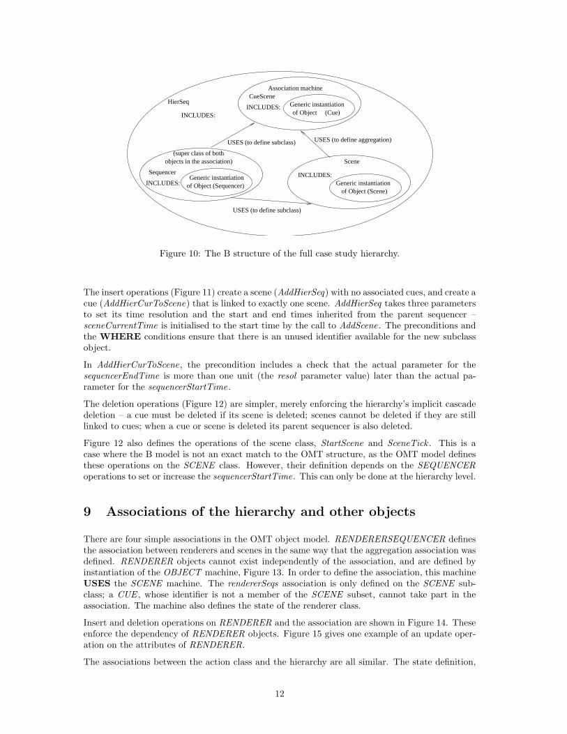
HIERSEQ contains no other state, and no initialisation; these are defined in the included machines.The structure of the hierarchy machines is shown in Figure 10.
HIERSEQ operates like an independent class, in that the interface to its operations provides accessto its data properties (the collected properties of its component machines). This is the only levelat which the component objects can pass information out of the system.
6Facon et al[4] also lists the variations and additions to these invariants, required when there is more than onesub-class, and when sub-classes may not overlap
11
Generic instantiation
Generic instantiationof Object (Cue)
INCLUDES:
Association machine
Sequencer
INCLUDES:
(super class of bothobjects in the association)
CueScene
INCLUDES:
USES (to define subclass)
Generic instantiation
Scene
INCLUDES:
USES (to define aggregation)
USES (to define subclass)
HierSeq
of Object (Sequencer)of Object (Scene)
Figure 10: The B structure of the full case study hierarchy.
The insert operations (Figure 11) create a scene (AddHierSeq) with no associated cues, and create acue (AddHierCurToScene) that is linked to exactly one scene. AddHierSeq takes three parametersto set its time resolution and the start and end times inherited from the parent sequencer –sceneCurrentTime is initialised to the start time by the call to AddScene. The preconditions andthe WHERE conditions ensure that there is an unused identifier available for the new subclassobject.
In AddHierCurToScene, the precondition includes a check that the actual parameter for thesequencerEndTime is more than one unit (the resol parameter value) later than the actual pa-rameter for the sequencerStartTime.
The deletion operations (Figure 12) are simpler, merely enforcing the hierarchy’s implicit cascadedeletion – a cue must be deleted if its scene is deleted; scenes cannot be deleted if they are stilllinked to cues; when a cue or scene is deleted its parent sequencer is also deleted.
Figure 12 also defines the operations of the scene class, StartScene and SceneTick . This is acase where the B model is not an exact match to the OMT structure, as the OMT model definesthese operations on the SCENE class. However, their definition depends on the SEQUENCERoperations to set or increase the sequencerStartTime. This can only be done at the hierarchy level.
9 Associations of the hierarchy and other objects
There are four simple associations in the OMT object model. RENDERERSEQUENCER definesthe association between renderers and scenes in the same way that the aggregation association wasdefined. RENDERER objects cannot exist independently of the association, and are defined byinstantiation of the OBJECT machine, Figure 13. In order to define the association, this machineUSES the SCENE machine. The rendererSeqs association is only defined on the SCENE sub-class; a CUE , whose identifier is not a member of the SCENE subset, cannot take part in theassociation. The machine also defines the state of the renderer class.
Insert and deletion operations on RENDERER and the association are shown in Figure 14. Theseenforce the dependency of RENDERER objects. Figure 15 gives one example of an update oper-ation on the attributes of RENDERER.
The associations between the action class and the hierarchy are all similar. The state definition,
12

seqId ←− AddHierSeq ( start , end , resol ) =PRE
start ∈ TIME ∧ end ∈ TIME ∧ resol ∈ TIME ∧ end ≥ start + resol∧ resol 6= 0 ∧ cues ∪ scenes ⊂ SEQUENCERID
THEN ANY sceneIdWHERE resol > 0 ∧ start < end∧ sceneId ∈ SEQUENCERID − ( cues ∪ scenes )
THEN
AddSequencer ( start , end , sceneId ) ‖ AddScene ( start , resol , sceneId )‖ seqId := sceneId
END
END ;
seqId ←− AddHierCueToScene ( cueStart , cueEnd , aScene ) =PRE
cueStart ∈ TIME ∧ cueEnd ∈ TIME ∧ aScene ∈ scenes ∧ cueEnd > cueStart∧ sequencers ⊂ SEQUENCERIDTHEN
ANY cueIdWHERE cueId ∈ SEQUENCERID − sequencers
THEN
AddSequencer ( cueStart , cueEnd , cueId ) ‖ AddCueToScene ( aScene , cueId )‖ seqId := cueId
END
END ;
Figure 11: Insert Operations of HIERSEQ for the Sequencer Hierarchy
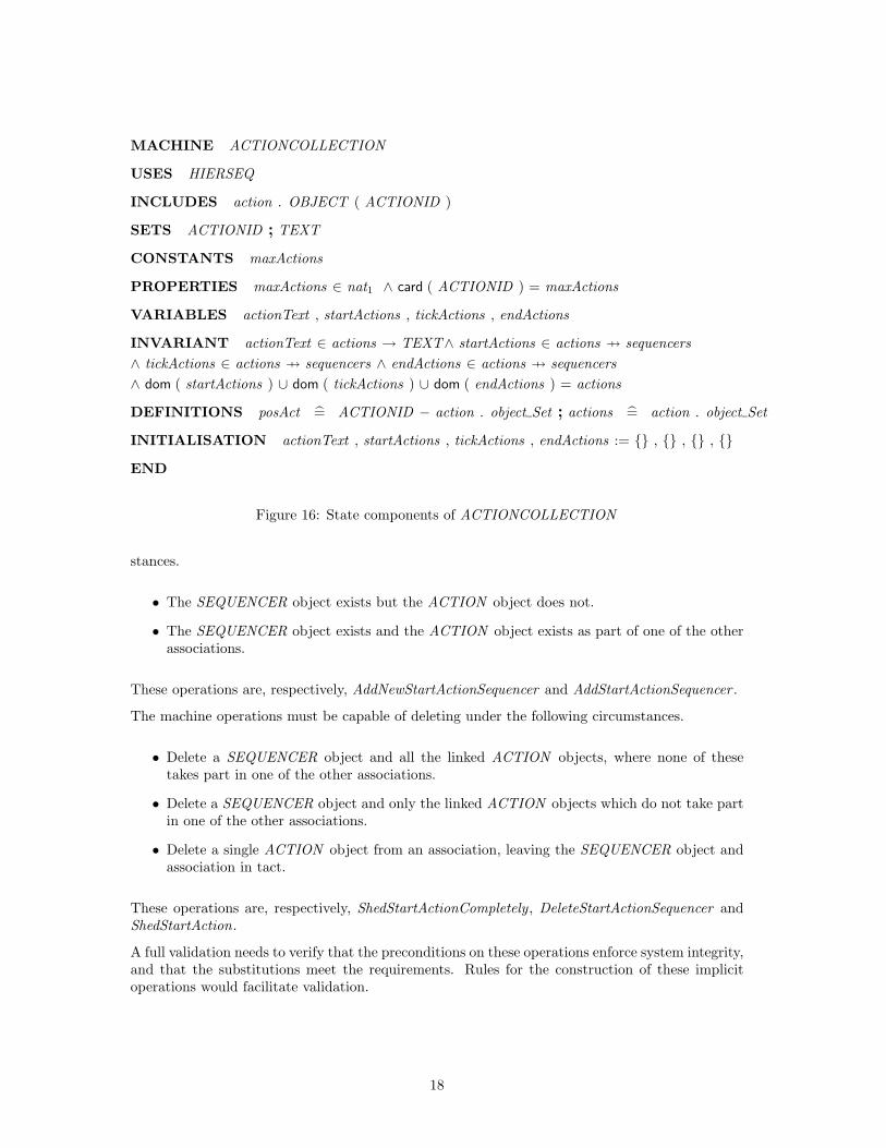
Figure 16, is analogous to that of the other associations, defining the associations and the actionclass attribute. However, the association representations here are partial functions from actionsto the hierarchy objects – not all actions take part in every association; each action can be linkedvia one or more of the associations; the combination of these associations is total, as expressed inthe last clause of the invariant.
Figure 17 gives sample operations from the ACTIONCOLLECTION machine. The operations tocreate and delete instances of the associations preserve the invariant by ensuring that an action isalways linked to the hierarchy via at least one association. The illustrated operations allow an exist-ing action to the added to the links of startAction (AddStartActionSequencer), and also allow a newaction to be created and linked to the hierarchy via startAction (AddNewStartActionSequencer).The delete operation DeleteStartActionSequencer removes the link to a particular sequencer ob-ject where an action has links to other sequencers. ShedStartAction deletes the startAction link ofan action that takes part in other associations. ShedStartActionCompletely is used to completelydelete a link whose action is not involved in any other links. These operations present a challengeto the proof tools of the B Tool, simply because of the complexity of the goals derived. All are,however, believed to be valid.
13

ShedCueSequencer ( cue ) =PRE
cue ∈ dom ( sceneCues )THEN
DeleteSequencer ( cue ) ‖ ShedCue ( cue )END ;
DeleteSceneCueSequencer ( scene ) =PRE
scene ∈ scenes∧ scene 6∈ ran ( sceneCues )THEN
DeleteScene ( scene ) ‖ DeleteSequencer ( scene )END ;
StartScene ( seqr ) =PRE
seqr ∈ scenesTHEN
SetCurrentTime ( seqr , sequencerStartTime ( seqr ) )END ;
SceneTick ( seqr ) =PRE
seqr ∈ scenesTHEN
IncrementCurrentTime ( seqr )END
END
Figure 12: HIERSEQ Delete operations and the operations of the SCENE class
10 Validation of the transcription
A problem arises in any transcription between notations that does not rely on automated formaltranslation, in ensuring that the two notations describe the same concepts. The problem is exacer-bated if (as here) the notations present different views of the system. The informal, diagrammatic,approach has a weaker semantic content than the formal representation, and is less able to expresssystem constraints. Its emphasis is on conveying visual summaries of the system, rather thanon elaborating the system requirements for that architecture. In the absence of a sound formaltranslation, El Koursi et al[6] propose that a range of validation mechanisms should be used toincrease confidence in the equivalence of the representations. The validation processes that theydescribe accord with the review guidelines for safety-oriented developments outlined by Parnas etal[17].
In an OMT to B transcription, there are several obvious checks that can be made.
Structure The B machines must capture not only the structure of the graphical summary thatis the OMT models, but must also attempt to capture implicit semantics.
Functionality The B must formally define the functionality expressed in the OMT models. Class
14

MACHINE RENDERERSEQUENCER
USES SCENE
INCLUDES Renderer . OBJECT ( RENDERERID )
SETS RENDERERID ; TIME ; COLOUR ; VIEWPORT
VARIABLES timeResolution , backgroundColour , frameCounter , viewport , rendererSeqs
DEFINITIONS sequencers = Sequencer . objectSet ; cues = Cue . objectSet ;scenes = Scene . objectSet ; rends = Renderer . objectSet ; TIME = nat
INVARIANT timeResolution ∈ rends → TIME ∧ backgroundColour ∈ rends → COLOUR∧ frameCounter ∈ rends → nat ∧ viewport ∈ rends → VIEWPORT∧ rendererSeqs ∈ rends 7→ scenes
INITIALISATIONtimeResolution , backgroundColour , frameCounter , viewport , rendererSeqs := {} , {} , {} , {} , {}
Figure 13: State components of RENDERERSEQUENCER
operations must be checked, and the actions on the state transition diagram.
Dynamics Model-based formal methods rely on preconditions to define the acceptable states inwhich changes can occur. The dynamic OMT models could be used to develop check lists offeatures which should be included in the B specification.
Interface The OMT models do not explicitly define the system’s interface with the outside world.However, there are implicit external interactions when events occur. By modelling the Binterface in terms of the inputs and outputs to operations in the highest-level machines, thedevelopers and clients could at least compare intent on the interface with the outside world.Other object-oriented models, such as those in the Fusion[3] method, provide the necessaryinformal source for such a validation check.
In this paper, the validation concentrates on the first group of checks. The dynamic checks are notrelevant, since the operations pertaining to the state transitions have been deliberately omitted.The functionality is not specified in detail in the original OMT case study, and is, in any case, notthe subject of this paper.
10.1 Checking Objects and Classes
It is relatively easy to check that all the OMT classes are defined in B machines. In addition,definition of attributes in these machines must be checked. Consideration should be given tostate invariants, such that it is made clear where these derive from the OMT and where these areintroduced by the author of the B machines.
Here, the B machines define classes by instantiating the OBJECT generic machine. The genericparameter introduces a set of known instances of the parameter type; the set type is defined inthe instantiating machine. The classes in the OMT model, and the corresponding B machines aresummarised in Table 1.
The definition of attributes is detailed in Table 2.
15

AddRendererSequencer ( aScene , rend , new Trs , new Bcol , new fr ctr , new Vpt ) =PRE
aScene ∈ scenes ∧ rend ∈ RENDERER ID − rends∧ new Trs ∈ TIME ∧ new Bcol ∈ COLOUR ∧ new fr ctr ∈ nat∧ new Vpt ∈ VIEWPORT
THEN
rendererSeqs := rendererSeqs ∪ { rend 7→ aScene }‖ timeResolution := timeResolution ∪ { rend 7→ new Trs }‖ backgroundColour := backgroundColour ∪ { rend 7→ new Bcol }‖ frameCounter := frameCounter ∪ { rend 7→ new fr ctr }‖ viewport := viewport ∪ { rend 7→ new Vpt } ‖ Renderer . Add object ( rend )
END ;
DeleteRendererSequence ( aScene ) =PRE
aScene ∈ ran ( rendererSeqs )THEN
rendererSeqs := rendererSeqs −B { aScene }END ;
ShedRenderer ( aScene , renderer ) =PRE
aScene ∈ scenes ∧ renderer ∈ rends∧ rendererSeqs ( renderer ) = aScene
THEN
rendererSeqs := { renderer } −C rendererSeqsEND
END
Figure 14: RENDERERSEQUENCER Operations
Note that the CUE class has no attributes of its own, and that the SCENE and CUE inherit theirattributes via the structure of the machines in the hierarchy.
Additional invariants should be listed for completeness; the most important one is probably theassertion that the identifiers of SCENE and CUE partition those of SEQUENCER.
10.2 Checking Hierarchies.
The hierarchy in the OMT model defines the SEQUENCER super-class and its two subclasses,SCENE and CUE . The transcription was validated using the visualisation of the application ofthe hierarchy and association rules (Figure 10). Assuming that the B representation of a generalhierarchy is adequate, we have therefore shown that the transcription is a valid representation ofthe hierarchy structure.
16
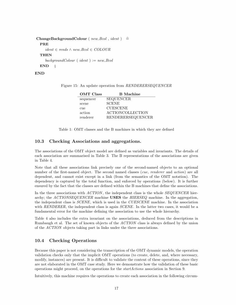
ChangeBackgroundColour ( new Bcol , ident ) =PRE
ident ∈ rends ∧ new Bcol ∈ COLOURTHEN
backgroundColour ( ident ) := new BcolEND ;
END
Figure 15: An update operation from RENDERERSEQUENCER
OMT Class B Machinesequencer SEQUENCERscene SCENEcue CUESCENEaction ACTIONCOLLECTIONrenderer RENDERERSEQUENCER
Table 1: OMT classes and the B machines in which they are defined
10.3 Checking Associations and aggregations.
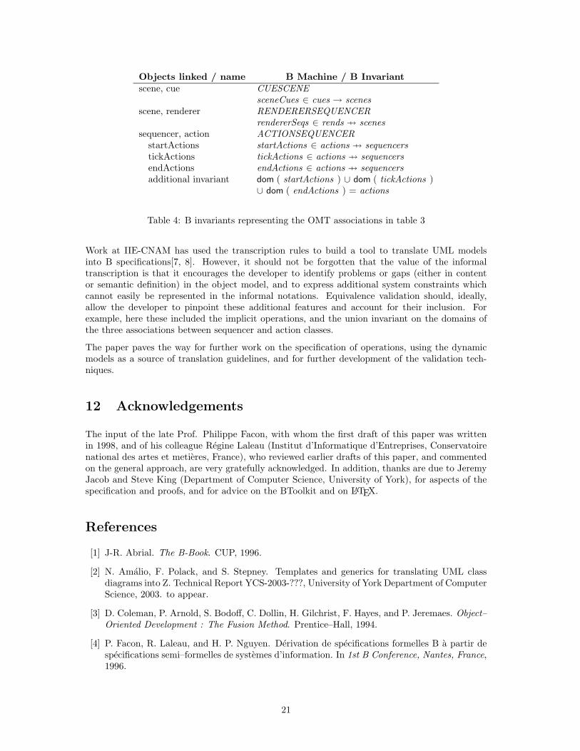
The associations of the OMT object model are defined as variables and invariants. The details ofeach association are summarised in Table 3. The B representations of the associations are givenin Table 4.
Note that all these associations link precisely one of the second-named objects to an optionalnumber of the first-named object. The second named classes (cue, renderer and action) are alldependent, and cannot exist except in a link (from the semantics of the OMT notation). Thedependency is captured by the total function, and enforced by operations (below). It is furtherensured by the fact that the classes are defined within the B machines that define the associations.
In the three associations with ACTION , the independent class is the whole SEQUENCER hier-archy; the ACTIONSEQUENCER machine USES the HIERSEQ machine. In the aggregation,the independent class is SCENE , which is used in the CUESCENE machine. In the associationwith RENDERER, the independent class is again SCENE . In the latter two cases, it would be afundamental error for the machine defining the association to use the whole hierarchy.
Table 4 also includes the extra invariant on the associations, deduced from the descriptions inRumbaugh et al. The set of known objects of the ACTION class is always defined by the unionof the ACTION objects taking part in links under the three associations.
10.4 Checking Operations
Because this paper is not considering the transcription of the OMT dynamic models, the operationvalidation checks only that the implicit OMT operations (to create, delete, and, where necessary,modify, instances) are present. It is difficult to validate the content of these operations, since theyare not elaborated in the OMT case study. Here we demonstrate how the validation of these basicoperations might proceed, on the operations for the startActions association in Section 9.
Intuitively, this machine requires the operations to create each association in the following circum-
17
MACHINE ACTIONCOLLECTION
USES HIERSEQ
INCLUDES action . OBJECT ( ACTIONID )
SETS ACTIONID ; TEXT
CONSTANTS maxActions
PROPERTIES maxActions ∈ nat1 ∧ card ( ACTIONID ) = maxActions
VARIABLES actionText , startActions , tickActions , endActions
INVARIANT actionText ∈ actions → TEXT∧ startActions ∈ actions 7→ sequencers∧ tickActions ∈ actions 7→ sequencers ∧ endActions ∈ actions 7→ sequencers∧ dom ( startActions ) ∪ dom ( tickActions ) ∪ dom ( endActions ) = actions
DEFINITIONS posAct = ACTIONID − action . object Set ; actions = action . object Set
INITIALISATION actionText , startActions , tickActions , endActions := {} , {} , {} , {}
END
Figure 16: State components of ACTIONCOLLECTION
stances.
• The SEQUENCER object exists but the ACTION object does not.
• The SEQUENCER object exists and the ACTION object exists as part of one of the otherassociations.
These operations are, respectively, AddNewStartActionSequencer and AddStartActionSequencer .
The machine operations must be capable of deleting under the following circumstances.
• Delete a SEQUENCER object and all the linked ACTION objects, where none of thesetakes part in one of the other associations.
• Delete a SEQUENCER object and only the linked ACTION objects which do not take partin one of the other associations.
• Delete a single ACTION object from an association, leaving the SEQUENCER object andassociation in tact.
These operations are, respectively, ShedStartActionCompletely , DeleteStartActionSequencer andShedStartAction.
A full validation needs to verify that the preconditions on these operations enforce system integrity,and that the substitutions meet the requirements. Rules for the construction of these implicitoperations would facilitate validation.
18

AddStartActionSequencer ( seqr , act ) =PRE
seqr ∈ sequencers ∧ act ∈ actionsTHEN
startActions ( act ) := seqrEND ;
newAction ←− AddNewStartActionSequencer ( seqr , newText ) =PRE
seqr ∈ sequencers ∧ newText ∈ TEXT ∧ posAct 6= {}THEN
LET aa BE aa ∈ posAct IN
startActions ( aa ) := seqr ‖ newAction := aa ‖ action . Add object ( aa )‖ actionText := actionText ∪ { aa 7→ newText }
END
END ;
DeleteStartActionSequencer ( seqr ) =PRE
seqr ∈ startActions [ dom ( tickActions ) ∪ dom ( endActions ) ]THEN
startActions := startActions −B { seqr }END ;
ShedStartAction ( act ) =PRE
act ∈ dom ( startActions ) ∩ ( dom ( tickActions ) ∪ dom ( endActions ) )THEN
startActions := { act } −C startActionsEND ;
ShedStartActionCompletely ( act ) =PRE
act ∈ dom ( startActions ) − ( dom ( tickActions ) ∪ dom ( endActions ) )THEN
startActions := { act } −C startActions ‖ actionText := { act } −C actionText‖ action . Delete object ( act )
END
END
Figure 17: Sample operations on ACTIONCOLLECTION
19

Class and Attribute B Invariantsequencer
startTime sequencerStartTime ∈ sequencers → TIMEendTime sequencerEndTime ∈ sequencers → TIME
ScenecurrentTime sceneCurrentTime ∈ scenes → TIMEtime resolution sceneTimeResolution ∈ scenes → TIME
Actiontext actionText ∈ actions → TEXT
Renderertime resolution timeResolution ∈ rends → TIMEbackground colour backgroundColour ∈ rends → COLOURframe counter frameCounter ∈ rends → natviewport viewport ∈ rends → VIEWPORT
Table 2: OMT object data properties and the B invariants in which they are defined
Objects linked association namescene, cue aggregation (1 to 0 or more) sceneCuesscene, renderer association (1 to 0 or more) rendererSeqssequencer, action association (1 to 0 or more) startActions
association (1 to 0 or more) tickActionsassociation (1 to 0 or more) endActions
Table 3: OMT associations in the object model
11 Conclusions
The paper demonstrates that translation rules derived for simple object-oriented classes and associ-ations in an information system specification can be applied to a more complex OMT specificationfor a different sort of system. The sorts of systems differ principally at lower levels (where realtime, persistence, and details of algorithmic approach are relevant); at the specification or analysislevel, the only fundamental difference is in the emphasis required on the component models (stateor objects, dynamics, function) to capture the system features.
One major advantage of using the B method is that the basic proofs on the internal consistencyof the state represented in the object model can be easily discharged. The majority are handledby the machine’s autoprover ; the few more complex goals can be demonstrated to be true, usingthe interprover with some additional set theory. The B method features designed to facilitateproof introduce some complications in the B specification. The method is not amenable to thedevelopment of generic structures to represent the standard components found in the informalnotation. In addition, the facilities for developing models in a modular manner which matchesthat of the informal models may inhibit the application of some of the guideline rules developed.This is partially demonstrated by the need to define three levels of machine to capture the semanticsof a class hierarchy; it would be more apparent when additional operations were added to capturethe dynamic features of the system.
In addition to providing an extended example of the formalisation of an OMT object model, thispaper considers the informal validation of the equivalence of the object model and the informally-derived B representation. The validation outlined begins to demonstrate how rigorous informalchecklists can be developed, so that, although exact correspondence cannot be proved, confidencein the equivalence can be enhanced.
20
Objects linked / name B Machine / B Invariantscene, cue CUESCENE
sceneCues ∈ cues → scenesscene, renderer RENDERERSEQUENCER
rendererSeqs ∈ rends 7→ scenessequencer, action ACTIONSEQUENCER
startActions startActions ∈ actions 7→ sequencerstickActions tickActions ∈ actions 7→ sequencersendActions endActions ∈ actions 7→ sequencersadditional invariant dom ( startActions ) ∪ dom ( tickActions )
∪ dom ( endActions ) = actions
Table 4: B invariants representing the OMT associations in table 3
Work at IIE-CNAM has used the transcription rules to build a tool to translate UML modelsinto B specifications[7, 8]. However, it should not be forgotten that the value of the informaltranscription is that it encourages the developer to identify problems or gaps (either in contentor semantic definition) in the object model, and to express additional system constraints whichcannot easily be represented in the informal notations. Equivalence validation should, ideally,allow the developer to pinpoint these additional features and account for their inclusion. Forexample, here these included the implicit operations, and the union invariant on the domains ofthe three associations between sequencer and action classes.
The paper paves the way for further work on the specification of operations, using the dynamicmodels as a source of translation guidelines, and for further development of the validation tech-niques.
12 Acknowledgements
The input of the late Prof. Philippe Facon, with whom the first draft of this paper was writtenin 1998, and of his colleague Regine Laleau (Institut d’Informatique d’Entreprises, Conservatoirenational des artes et metieres, France), who reviewed earlier drafts of this paper, and commentedon the general approach, are very gratefully acknowledged. In addition, thanks are due to JeremyJacob and Steve King (Department of Computer Science, University of York), for aspects of thespecification and proofs, and for advice on the BToolkit and on LATEX.
References
[1] J-R. Abrial. The B-Book. CUP, 1996.
[2] N. Amalio, F. Polack, and S. Stepney. Templates and generics for translating UML classdiagrams into Z. Technical Report YCS-2003-???, University of York Department of ComputerScience, 2003. to appear.
[3] D. Coleman, P. Arnold, S. Bodoff, C. Dollin, H. Gilchrist, F. Hayes, and P. Jeremaes. Object–Oriented Development : The Fusion Method. Prentice–Hall, 1994.
[4] P. Facon, R. Laleau, and H. P. Nguyen. Derivation de specifications formelles B a partir despecifications semi–formelles de systemes d’information. In 1st B Conference, Nantes, France,1996.
21

[5] P. Facon, R. Laleau, and H. P. Nguyen. Mapping object diagrams into B specifications. InLeeds Methods Integration Workshop. Leeds Metropolitan University, March 1996.
[6] M. El Koursi and G. Mariano. Safety critical software assessment : Past experience and newapproach. In 1st B Conference, Nantes, France, 1996.
[7] R. Laleau and A. Mammar. An overview of a method and its support tool for generating Bspecifications from UML notations. In ASE: 15th IEEE Conference on Automated SoftwareEngineering, Grenoble, France. IEEE Computer Society Press, September 2000.
[8] R. Laleau and A. Mammar. An automatic generation of B specifications from well-definedUML notations for database applications. In ISPS’2001: 5th International Symposium onProgramming Systems, Algiers, Algeria, May 2001, May 2001.
[9] R. Laleau and F. Polack. Specification of integrity-preserving operations in informationsystems by using a formal UML-based language. Information and Software Technology,43(12):693–704, November 2001.
[10] R. Laleau and F. Polack. Coming and going from UML to B : a proposal to support traceabilityin rigorous is development. In ZB2002, second international conferene of B and Z users,Grenoble, France, volume 2272 of LNCS, pages 517–534. Springer Verlag, January 2002.
[11] K. Lano. The B Language and Method. Springer Verlag, 1996.
[12] K. Lano and H. Haughton. Improving the process of system specification and refinement inB. In D. Till, editor, 6th Refinement Workshop, Workshops in Computing. Springer Verlag,1994.
[13] K. C. Mander and F. Polack. Rigorous specification using structured systems analysis and Z.Information and Software Technology, 37(5):285–291, 1995.
[14] B. Meyer. Object-oriented software construction. Prentice Hall, 1997.
[15] N. Nagui-Raiss. A formal software specification tool using the entity relationship model. InD. Till, editor, 6th Refinement Workshop, Workshops in Computing. Springer Verlag, 1994.
[16] H. P. Nguyen. Derivation de specifications formelles B a partir de specifications semi–formelles. PhD thesis, Laboratoire CEDRIC, Conservatoire National des Arts et Metiers,Evry, December 1998. Available from www.iie.cnam.fr/˜ laleau/thesePHNguyen.ps-gz.
[17] D. L. Parnas, van Schouwen, and P. K. Shu. Evaluation of safety critical software. Commu-nications of the ACM, 33(6), 1990.
[18] F. Polack and R. Laleau. A rigorous metamodel for UML static conceptual modelling ofinformation systems. In CAiSE2001: 13th International Conference on Advanced InformationSystems Engineering, Interlaken, Switzerland, volume 2068 of LNCS, pages 402–416. SpringerVerlag, June 2001.
[19] F. Polack and S. Stepney. System development using Z generics. In FM99, Toulouse, France,volume 1708 and 1709 of LNCS, pages 1048–1067. Springer Verlag, 1999.
[20] F. Polack, M. Whiston, and K. C. Mander. The SAZ method version 1.1. Technical ReportYCS207, University of York, January 1994.
[21] F. A. C. Polack and K. C. Mander. Software quality assurance using the SAZ method. InEighth Annual Z User Meeting, Cambridge, June 1994, pages 230–249. Springer Verlag, 1994.
[22] J. Rumbaugh, M. Blaha, W. Premerlani, F. Eddy, and W. Lorensen. Object-Oriented Mod-elling and Design. Prentice Hall, 1991.
[23] R. Shore. An object-oriented approach to B. In 1st B Conference, Nantes, France, 1996.
22