exploring fatigue behavior of connecting rod made of · pdf file ·...
TRANSCRIPT
International Research Journal of Engineering and Technology (IRJET) e-ISSN: 2395 -0056
Volume: 04 Issue: 04 | Apr -2017 www.irjet.net p-ISSN: 2395-0072
© 2017, IRJET | Impact Factor value: 5.181 | ISO 9001:2008 Certified Journal | Page 2735
Exploring fatigue behavior of connecting rod made of Austempered
Ductile Iron
Prashant S. Tripathi1, P. Frank Crasta2
1Student,Mechanical Engineering, D. J Sanghvi College of Engineering,Maharashtra,India. 2Asst. Professor, Dept. of Mechanical Engineering, D. J Sanghvi College of Engineering,Maharashtra,India.
---------------------------------------------------------------------***---------------------------------------------------------------------Abstract - This study explores fatigue behavior of Austempered Ductile Iron (grade 1050) connecting rod. It is estimated that 50-90% of structural failure is due to fatigue . Fatigue is the primary cause of failure of connecting rods due to cyclic loading and presence of stress concentrations at the critical areas. A literature review on several relevant aspects of this work is also provided. The parametric model of connecting rod was modeled using CATIA V5 R20. Model was then imported in ANSYS 15.0, a FEA tool to carry out the fatigue analysis. Also this project includes a comparison of fatigue behavior of ADI with AISI 4340 steel ,a medium carbon low alloy steel. Fatigue study was performed based on Stress Life (SxN) theory. The focus of fatigue in ANSYS is to provide useful information to the design engineer when fatigue failure may be a concern. Key Words: Fatigue, Stress, Austempered ductile Iron, Catia V5 R20, Ansys 15.0, Finite Element Analysis , Stress Life theory
1.INTRODUCTION
Nearly 60 years after its discovery ADI(Austempered Ductile Iron) is still widely regarded as a “new material”. A major reason for this was the slow commercialisation of the Austempering process. ADI remained a laboratory curiosity until 1972 when a limited facility was set up to process a small compressor crankshaft in the USA. However the first truly viable commercial service was delayed until the introduction of new furnace developments at Applied Process Inc in Michigan during 1984. Considerable process modelling and material evaluation has followed, resulting in wider understanding and acceptance of ADI.The intense competition in the marketplace for superior products has motivated the evolution of high performance components, which must be designed and fabricated economically. Austempered ductile iron (ADI) is being applied increasingly by the automotive industries as the cost and performance benefits are recognised.The price of ADI material is lower per kilo than steel or aluminium, but this accounts for only a fraction of the potential savings as an ADI designed component can save cost at each stage of manufacture. ADI equivalents can then be produced for less than a steel forging or at half the cost of aluminium parts. Several factors favour ADI in value engineering.Few of them are mentioned below:
a)Strength comparable to steel b)Improved noise damping c)Excellent fatigue strength d)Low energy content e)Best value
The Austempered Ductile Iron (ADI) has experienced a remarkable progress in industrial applications, becoming an excellent and very competitive alternative material in engineering design, due to its excellent combination of mechanical properties and manufacturing costs.The different Grades of ADI have significantly higher mechanical properties compared to the standard grades of cast iron, making a special remark to the strength, toughness, ductility and wear resistance properties. Depending on the conditions of the heat treatment applied, ADI materials can achieve comparable properties to forged or cast low alloyed steels.The standard grades of ADI and its typical mechanical properties according to ASTM A897/97M-15(SI units) is given below: Table-1: Standard grades of Austempered Ductile Iron
1.1 Properties of ADI
Figure 1 shows the strength of Ductile Iron and ADI compared to cast and forged steels. Ductile Iron has commercially replaced as cast and forged steels in the lower strength region, now ADI is finding applications in the higher regions. As shown in Figure 2, the yield strength of ADI is over three times that of the best cast or forged aluminum. In addition ADI weighs only 2.4 times more than aluminum and

International Research Journal of Engineering and Technology (IRJET) e-ISSN: 2395 -0056
Volume: 04 Issue: 04 | Apr -2017 www.irjet.net p-ISSN: 2395-0072
© 2017, IRJET | Impact Factor value: 5.181 | ISO 9001:2008 Certified Journal | Page 2736
is 2.3 times stiffer. ADI is also 10% less dense than steel [9].
Fig-1: Comparative strength of steel vs. Ductile Iron.
Fig-2: ADI vs. Aluminum.
Therefore, when you compare the relative weight per unit of yield strength of ADI with that of various aluminums and steels (Figure 3) it is easy to see the engineering and design advantages inherent in ADI.
Fig-3: Relative weight per unit of yield strength
As shown in Figure 4, ADI has fatigue properties equal or superior to those of forged steels. When subjected to surface treatments such as rolling, peening or machining after heat treatment, the fatigue strength of ADI is increased significantly.
Fig-4 : Comparison of fatigue properties of ADI and
different grades of forged steel.
1.2 Service loads on connecting rod Connecting rod is submitted to mass and gas forces. The superposition of these two forces results in the axial force, which acts on the connecting rod. The gas force is determined by the speed of rotation, the masses of the piston, gudgeon pin and oscillating part of the connecting rod consisting of the small end and the shank. Figure 5 shows axial loading (Fay) due to gas pressure and rotational mass forces. Bending moments (Mb,xy, Mb,zy) originate due to eccentricities, crankshaft, case wall deformation, and rotational mass force, which can be determined only by strain analyses in engine (Sonsino, 1996).
Fig-5: The origin of stresses on connecting rod
2. LITERATURE REVIEW
The loading experienced by connecting rods analyzed by Sonsino (1996) [7] . Connecting rods are submitted to mass and gas forces. The superposition of mass and gas forces produce the axial force, which acts on the connecting rod. Axial loading can be calculated by the
International Research Journal of Engineering and Technology (IRJET) e-ISSN: 2395 -0056
Volume: 04 Issue: 04 | Apr -2017 www.irjet.net p-ISSN: 2395-0072
© 2017, IRJET | Impact Factor value: 5.181 | ISO 9001:2008 Certified Journal | Page 2737
knowledge of engine pressure and rotational speed. Connecting rods also experience bending moments due to eccentricities, crankshaft and rotational mass forces, which can be determined by strain analysis in an engine.He studied the fatigue aspect by operating a connecting rod for about 2x10⁹ cycles.Test loads being higher than the calculated load,resulted in failures occurring mainly from fretting corrosion between gudgeon pin and small end.
Majidpour et al. (2002) [5] discussed to develop dynamic stress analysis using FE techniques and stress-time history generations. Inertia forces are composed of two parts. The first part is inertia of reciprocating masses that acts on the pin end and its direction changes with respect to the piston acceleration. The second part includes centrifugal forces, which act on the connecting rod in a distributed manner. The maximum moment occurs when the crank is perpendicular to the rod. At the top dead center point of every cycle, maximum tension and compression forces occur. It was observed that inertia load is proportional to the engine speed.
Webster et al. (1983) [8] explained the loading of connecting rod in an engine. In this study the tension and compression were obtained from experimental results. For tension loading the crank ends and piston ends were found to have a sinusoidal distribution on the contact surface with pins and connecting rod whereas,in compression, a uniform distribution over the contact area.The stresses found in the shaft and cap exhibited the beam and axial loading distribution.It was concluded that the highest stress levels occurred in four locations: the upper area of the cap end on the axis of symmetry, the transition region of the bolt section and the lower rib, the transition region of the lower rib and the shaft, and the connecting rod’s bolt head.
Adila Afzal (2004) [1] carried out the fatigue behavior analysis of forged steel and powder metal connecting rods.Strain-controlled fatigue properties as well as monotonic and cyclic deformation behaviors of the two materials were evaluated and compared.Also,connecting rods made of C-70 steel were tested and the results were compared with forged steel and powder metal connecting rods.The SN curves of the two connecting rods were also evaluated from the bench tests which were obtained under R=-1.25 constant amplitude axial loading conditions.Thereafter using the SN approach the life predictions of the connecting rods were evaluated.To account for the mean stress effects Goodman equation was used.Fractography of the connecting rod fracture surfaces were also conducted.
Mirehei, M. Hedayati Zadeh, A. Jafari, M. Omid (2008) [6] carried out the analysis of fatigue strength of a connecting rod.The fatigue analysis of the connecting rod of universal tractor was carried out by ANSYS ,a FEA software application and also its life prediction was carried out. The fatigue phenomenon occurring due to the cyclic loadings affects the connecting rod behavior and also to consider the more saving in time and costs were the reason for performing this research as the two are very significant
parameters relevant to manufacturing. The results of the research showed that with fully reverse loading the life cycle of a connecting rod can be estimated and also the critical points can be found from where more possibly the crack growth initiates from.
Endurance limit is a primary design criterion for the connecting rod.The factors, which effect the fatigue strength in PF connecting rod are metallurgical structure, hardness of the material, density, depth of decarbuized layer and surface roughness, such was reported by Imahashi et al. (1984) [3]. They conducted constant amplitude, load-controlled component axial fatigue tests on PF connecting rods. The fatigue behaviour were compared to SAE 1055 steel. They concluded that fatigue strength or fatigue behavior of a connecting rod is largely affected by its hardness.
M. Ravichandran (2013) [4] discussed the design of connecting rod of internal combustion engine using the topology optimization. The mesh convergence analysis was performed to select the best mesh for the analysis. To achieve the objectives of optimization the topology optimization technique is used which is to reduce the weight of the connecting rod. The crank end is suggested to be redesign based on the topology optimization results. The optimized connecting rod is 11.7% lighter and predicted low maximum stress compare to initial design. For future research, the optimization should cover on material optimization to increase the strength of the connecting rod.
Finite element analysis was used to optimize the connecting rod model in a study by Balasubramanian et al. (1991) [2]. The connecting rod load was broken down into various individual loads for the simulation and the actual stress was obtained by superposition. The individual loads were the inertia load, firing load, press fit of the bearing shell, and bolt forces. These individual load cases were analyzed based on alternating load, lateral acceleration, buckling, and free-free vibrations. They state that using 2-D shell model ignores the fact that crank pin and piston pin deflect when subjected to firing or inertia loads, and that the load perpendicular to the plane of the connecting rod is not constant. With 3-D model it is possible to take account of bolt geometry.
3. EXPERIMENTAL WORK The objective of Finite Element Analysis (FEA) is to investigate stresses experienced by the connecting rod. The stresses obtained can then be used to predict the fatigue life, and determine the expected failure regions. Step 1: CAD model generation
International Research Journal of Engineering and Technology (IRJET) e-ISSN: 2395 -0056
Volume: 04 Issue: 04 | Apr -2017 www.irjet.net p-ISSN: 2395-0072
© 2017, IRJET | Impact Factor value: 5.181 | ISO 9001:2008 Certified Journal | Page 2738
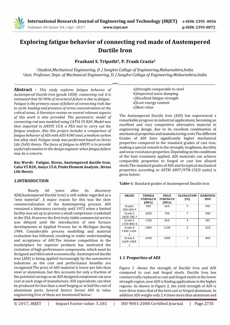
Fig-6 : Detailed drawing of Connecting Rod
Fig-7 : Solid model of connecting rod Step 2: Mesh Generation
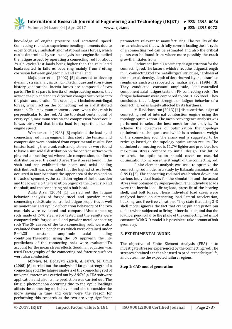
The CAD model of the connecting rod was imported as (.igs) file to Ansys 15.0. After importing the file, the free edges of the model were rectified as accuracy of the results is directly proportional to element quality. Hence the quality criteria were followed strictly. Patch independent algorithm was used with tetrahedrons elements.The minimum element was assigned as 1.8 mm and a face sizing of 1.1 mm was given at the faces of the connecting rod where the stress was maximum.It is the most important part of an analysis and can determined the efficiency and effectiveness of an analysis. Therefore, a lot of time is given to meshing of complex models.
Fig-8:Meshed model of connecting rod
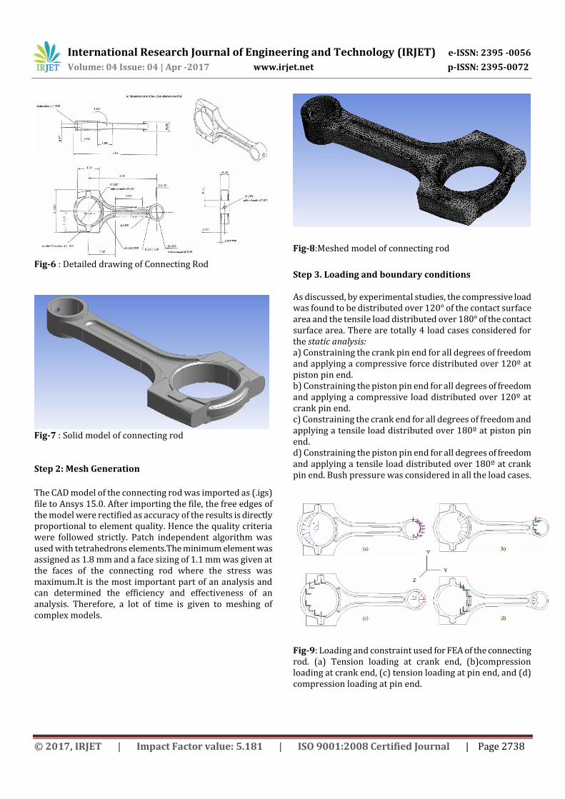
Step 3. Loading and boundary conditions As discussed, by experimental studies, the compressive load was found to be distributed over 120° of the contact surface area and the tensile load distributed over 180° of the contact surface area. There are totally 4 load cases considered for the static analysis: a) Constraining the crank pin end for all degrees of freedom and applying a compressive force distributed over 120º at piston pin end. b) Constraining the piston pin end for all degrees of freedom and applying a compressive load distributed over 120º at crank pin end. c) Constraining the crank end for all degrees of freedom and applying a tensile load distributed over 180º at piston pin end. d) Constraining the piston pin end for all degrees of freedom and applying a tensile load distributed over 180º at crank pin end. Bush pressure was considered in all the load cases.
Fig-9: Loading and constraint used for FEA of the connecting rod. (a) Tension loading at crank end, (b)compression loading at crank end, (c) tension loading at pin end, and (d) compression loading at pin end.

International Research Journal of Engineering and Technology (IRJET) e-ISSN: 2395 -0056
Volume: 04 Issue: 04 | Apr -2017 www.irjet.net p-ISSN: 2395-0072
© 2017, IRJET | Impact Factor value: 5.181 | ISO 9001:2008 Certified Journal | Page 2739
4. RESULTS 4.1. Material properties A comparison of fatigue behavior of ADI 1050 connecting rod and AISI 4340 medium carbon steel is also performed.The properties of both the materials are tabulated below.
Table-2:Properties of ADI 1050 and AISI 4340 steel
4.2 Fatigue analysis Fatigue calcualtions were performed for constant amplitude fully reversed loading.The Stress-Life theory was used and the Gerber equation was used to account for the mean stress effects.The Gerber theory provides a good fit fo ductile metals for tensile mean stresses.
Fig-10: Loading type and mean stress theory
Several results for evaluating fatigue are available to the user.Some are contour plots of a specific result over the model while others give information about the most damaged point in the model.
a) Fatigue Life
This result contour plot shows the available life for the given fatigue analysis. If loading is of constant amplitude, this represents the number of cycles until the part will fail due to fatigue.If the alternating stress is lower than the lowest alternating stress defined in the S-N curves, that life (cycles) will be used (in this example, max cycles to failure in S-N curve is 1e7, so that is max life shown). But most connecting rod failures occur in tension at high rpm on the exhaust upstroke.
Fig-11: Life contour plot for tension at crank end
Fig-12: Life contour plot for tension at piston pin end
Fig-13: Life contour plot for compression at crank end
Fig-14 : Life contour plot for compression at piston pin end
Property Units ADI 1050 AISI 4340 steel Density g/cc 7.0872 7.75
Ultimate tensile strength
Mpa 1050 825
Tensile yield strength
Mpa 700 467
Young's modulus
Gpa 157.9 192
Poisson’s ratio _ 0.25 0.27
Fatigue strength coefficient(sf')
Mpa 2720 1232
Fatigue strength exponent(b)
_ -0.146 -0.1

International Research Journal of Engineering and Technology (IRJET) e-ISSN: 2395 -0056
Volume: 04 Issue: 04 | Apr -2017 www.irjet.net p-ISSN: 2395-0072
© 2017, IRJET | Impact Factor value: 5.181 | ISO 9001:2008 Certified Journal | Page 2740
The fatigue life results for the connecting rod made of ADI 1050 at the given four loading conditions are tabulated below, Table-3:Minimum fatigue life for ADI 1050 connecting rod
Sr.no. Loading conditions Fatigue Life(cycles)
1. Tensile at crank
end(180°) 4089.9
2. Tensile at piston pin
end(180°) 0
3. Compression at crank
end(120°) 8.66x10⁶
4. Compression at piston
pin end (120°) 7.53x10⁵
b) Fatigue Damage
This result contour plot shows fatigue damage at a given design life. Fatigue damage is defined as the design life divided by the available life. This result may be scoped. The default design life may be set through the Control Panel. For Fatigue Damage, values greater than 1 indicate failure before the design life is reached.
Fig-15: Damage contour plot for tension at crank end
Fig-16:Damage contour plot for tension at piston pin end
Fig-17: Damage contour plot for compression at crank end
Fig-18: Damage contour plot for compression at piston pin end The fatigue damage results for the connecting rod made of ADI 1050 at the given four loading conditions are tabulated below, Table-4:Fatigue damage results for ADI 1050 connecting rod
Sr.no. Loading conditions Fatigue
Damage(cycles)
1. Tensile at crank
end(180°) 2.441x10⁵
2. Tensile at piston pin
end(180°) 1032
3. Compression at crank
end(120°) 115.36
4. Compression at
piston pin end (120°) 1326.7
c) Fatigue Safety Factor
This result contour plot shows the factor of safety with respect to a fatigue failure at a given design life. The maximum reported safety factor value is 15. Like damage and life, this result may be scoped. For Fatigue Safety Factor, values less than one indicate failure before the design life is reached.
International Research Journal of Engineering and Technology (IRJET) e-ISSN: 2395 -0056
Volume: 04 Issue: 04 | Apr -2017 www.irjet.net p-ISSN: 2395-0072
© 2017, IRJET | Impact Factor value: 5.181 | ISO 9001:2008 Certified Journal | Page 2741
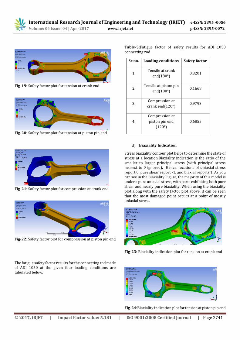
Fig-19: Safety factor plot for tension at crank end
Fig-20: Safety factor plot for tension at piston pin end.
Fig-21: Safety factor plot for compression at crank end
Fig-22: Safety factor plot for compression at piston pin end The fatigue safety factor results for the connecting rod made of ADI 1050 at the given four loading conditions are tabulated below,
Table-5:Fatigue factor of safety results for ADI 1050 connecting rod
Sr.no. Loading conditions Safety factor
1. Tensile at crank
end(180°) 0.3201
2. Tensile at piston pin
end(180°) 0.1668
3. Compression at
crank end(120°) 0.9793
4.
Compression at
piston pin end
(120°)
0.6855
d) Biaxiality Indication
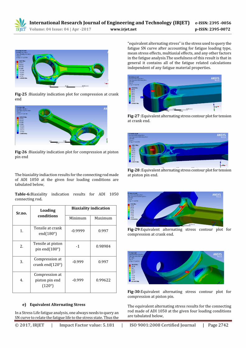
Stress biaxiality contour plot helps to determine the state of stress at a location.Biaxiality indication is the ratio of the smaller to larger principal stress (with principal stress nearest to 0 ignored). Hence, locations of uniaxial stress report 0, pure shear report -1, and biaxial reports 1. As you can see in the Biaxiality Figure, the majority of this model is under a pure uniaxial stress, with parts exhibiting both pure shear and nearly pure biaxiality. When using the biaxiality plot along with the safety factor plot above, it can be seen that the most damaged point occurs at a point of mostly uniaxial stress.
Fig-23: Biaxiality indication plot for tension at crank end
Fig-24:Biaxiality indication plot for tension at piston pin end
International Research Journal of Engineering and Technology (IRJET) e-ISSN: 2395 -0056
Volume: 04 Issue: 04 | Apr -2017 www.irjet.net p-ISSN: 2395-0072
© 2017, IRJET | Impact Factor value: 5.181 | ISO 9001:2008 Certified Journal | Page 2742
Fig-25 :Biaxiality indication plot for compression at crank end
Fig-26 :Biaxiality indication plot for compression at piston pin end
The biaxiality indiaction results for the connecting rod made of ADI 1050 at the given four loading conditions are tabulated below, Table-6:Biaxiality indication results for ADI 1050 connecting rod.
Sr.no. Loading
conditions
Biaxiality indication
Minimum Maximum
1. Tensile at crank
end(180°) -0.9999 0.997
2. Tensile at piston
pin end(180°) -1 0.98984
3. Compression at
crank end(120°) -0.999 0.997
4.
Compression at
piston pin end
(120°)
-0.999 0.99622
e) Equivalent Alternating Stress
In a Stress Life fatigue analysis, one always needs to query an SN curve to relate the fatigue life to the stress state. Thus the
“equivalent alternating stress” is the stress used to query the fatigue SN curve after accounting for fatigue loading type, mean stress effects, multiaxial effects, and any other factors in the fatigue analysis.The usefulness of this result is that in general it contains all of the fatigue related calculations independent of any fatigue material properties.
Fig-27 :Equivalent alternating stress contour plot for tension at crank end.
Fig-28 :Equivalent alternating stress contour plot for tension at piston pin end.
Fig-29:Equivalent alternating stress contour plot for compression at crank end.
Fig-30:Equivalent alternating stress contour plot for compression at piston pin. The equivalent alternating stress results for the connecting rod made of ADI 1050 at the given four loading conditions are tabulated below,

International Research Journal of Engineering and Technology (IRJET) e-ISSN: 2395 -0056
Volume: 04 Issue: 04 | Apr -2017 www.irjet.net p-ISSN: 2395-0072
© 2017, IRJET | Impact Factor value: 5.181 | ISO 9001:2008 Certified Journal | Page 2743
Table-7:Equivalent alternating stress results for ADI 1050 connecting rod
Sr.no. Loading
conditions
Equivalent
alternating
stress(Mpa)
1. Tensile at crank
end(180°) 729.96
2. Tensile at piston
pin end(180°) 1400.7
3. Compression at
crank end(120°) 238.6
4.
Compression at
piston pin end
(120°)
340.83
f) Fatigue Sensitivity:
A fatigue sensitivity chart displays how life, damage, or safety factor at the critical location varies with respect to load.Load variation limits can be input (including negative percentages). The user may set the number of fill points as well as the load variation limits. For example, the user may wish to see the sensitivity of the model’s life if the FE load was 50% of the current load up to if the load 150% of the current load. A value of 100% corresponds to the life at the current loading on the model.
Fig-31:Fatigue sensitivity plot for tension at crank end.
Fig-32:Fatigue sensitivity plot for tension at piston pin end.
Fig-33:Fatigue sensitivity plot for compression at crank end.
Fig-34:Fatigue sensitivity plot for compression at piston pin.
Similarly,the fatigue analysis was carried out for AISI 4340 steel,a medium carbon low alloy steel.AISI 4340 steel is extensively used for manufacturing connecting rods.
A proper comparision of fatigue behavior of both the materials i.e. ADI 1050 and AISI4340 steel is given below in a tabulated form.
International Research Journal of Engineering and Technology (IRJET) e-ISSN: 2395 -0056
Volume: 04 Issue: 04 | Apr -2017 www.irjet.net p-ISSN: 2395-0072
© 2017, IRJET | Impact Factor value: 5.181 | ISO 9001:2008 Certified Journal | Page 2744
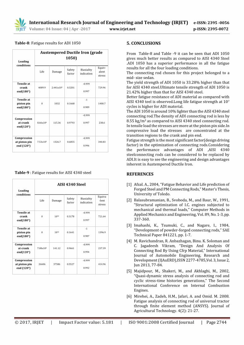
Table-8: Fatigue results for ADI 1050
Loading
conditions
Austempered Ductile Iron (grade
1050)
Life Damage Safety
factor
Biaxiality
indication
Equiv-
alent
stress
Tensile at
crank
end(180°)
4089.9 2.441x10⁵ 0.3201
-0.999
0.997
729.96
Tensile at
piston pin
end(180°)
0 1032 0.1668
-1
0.989
1400.7
Compression
at crank
end(120°)
8.66x10⁶ 115.36 0.9793
-0.999
0.997
238.6
Compression
at piston pin
end (120°)
7.53x10⁵ 1326.7 0.6855
-0.999
0.996
340.83
Table-9 : Fatigue results for AISI 4340 steel
Loading
conditions
AISI 4340 Steel
Life Damage Safety
factor
Biaxiality
indication
Equiva
-lent
stress
Tensile at
crank
end(180°)
0 1032 0.3178
-0.999
0.997
721.64
Tensile at
piston pin
end(180°)
0 1032 0.1641
-1
0.987
1396.9
Compression
at crank
end(120°)
7.08x10⁶ 141.12 0.9661
-0.999
0.994
237.39
Compression
at piston pin
end (120°)
26606 37586 0.5527
-0.999
0.992
414.96
5. CONCLUSIONS From Table-8 and Table -9 it can be seen that ADI 1050 gives much better results as compared to AISI 4340 Steel .ADI 1050 has a superior performance in all the fatigue results for all the four loading conditions. The connecting rod chosen for this project belonged to a mid- size sedan. The yield strength of ADI 1050 is 33.28% higher than that for AISI 4340 steel.Ultimate tensile strength of ADI 1050 is 21.42% higher than that for AISI 4340 steel. Better fatigue resistance of ADI material as compared with AISI 4340 teel is observed.Long life fatigue strength at 107 cycles is higher for ADI material. The ADI 1050 is around 10% lighter than the AISI 4340 steel connecting rod.The density of ADI connecting rod is less by 8.55 kg/m3 as compared to AISI 4340 steel connecting rod. In tensile load the stresses are more at the piston pin side.In compressive load the stresses are concentrated at the transition regions to the crank and pin end. Fatigue strength is the most significant factor(design driving factor) in the optimization of connecting rods.Considering the performance advantages of ADI ,AISI 4340 steelconnecting rods can be considered to be replaced by ADI.It is easy to see the engineering and design advantages inherent in Austempered Ductile Iron.
REFERENCES [1] Afzal. A., 2004, “Fatigue Behavior and Life prediction of
Forged Steel and PM Connecting Rods,” Master’s Thesis, University of Toledo.
[2] Balasubramanian, B., Svoboda, M., and Baur, W., 1991, “Structural optimization of I.C. engines subjected to mechanical and thermal loads,” Computer Methods in Applied Mechanics and Engineering, Vol. 89, No. 1-3, pp. 337-360.
[3] Imahashi, K., Tsumuki, C., and Nagare, I., 1984, “Development of powder-forged connecting rods,” SAE Technical Paper 841221, pp. 1-7.
[4] M. Ravichandran, R. Anbazhagan, Binu. K. Soloman and C. Jagadeesh Vikram, “Design And Analysis Of Connecting Rod By Using Cfrp Material,” International Journal of Automobile Engineering, Research and Development (IJAuERD),ISSN 2277-4785,Vol. 3, Issue 2, Jun 2013, 77-84.
[5] Majidpour, M., Shakeri, M., and Akhlaghi, M., 2002, “Quasi-dynamic stress analysis of connecting rod and cyclic stress-time histories generations,” The Second International Conference on Internal Combustion Engines.
[6] Mirehei, A., Zadeh, H.M., Jafari, A. and Omid. M. 2008. Fatigue analysis of connecting rod of universal tractor through finite element method (ANSYS). Journal of Agricultural Technology. 4(2): 21-27.
International Research Journal of Engineering and Technology (IRJET) e-ISSN: 2395 -0056
Volume: 04 Issue: 04 | Apr -2017 www.irjet.net p-ISSN: 2395-0072
© 2017, IRJET | Impact Factor value: 5.181 | ISO 9001:2008 Certified Journal | Page 2745
[7] Sonsino, C. M., 1996, “Fatigue design of high loaded PM parts,” Metal Powder Report, Vol. 51, Issue: 6, pp. 36-45.
[8] Webster, W. D., Coffell, R., and Alfaro, D., 1983, “A three dimensional finite elementanalysis of a high speed diesel engine connecting rod,” SAE Technical Paper 831322, pp.
83-96.
[9] www.ductile.org
[10] www.appliedprocess.com