exploring depths of knowledge 1 kernex microsystems a presentation on train collision avoidance...
TRANSCRIPT
Exploring Depths of Knowledge
KERNEX MICROSYSTEMS
A Presentation on
Train Collision Avoidance System (TCAS)
Exploring Depths of Knowledge
• TCAS Development project was awarded to 3 TCAS Development project was awarded to 3 Companies, as belowCompanies, as below::
Package A- 140 KM awarded to MedhaPackage A- 140 KM awarded to Medha
Package B- 70 KM awarded to KernexPackage B- 70 KM awarded to Kernex
Package C- 40 Km awarded to HBLPackage C- 40 Km awarded to HBL
TCAS Project

Exploring Depths of Knowledge
TCAS Project - location map

Exploring Depths of Knowledge
1." Package -"B"
Package B (Kernex Scope) - location map
Exploring Depths of Knowledge
• Safety Prevention of SPAD Control of Speed at PSR/TSR Facility of SOS Prevention of Collision during NI Working
• Operational Simple Operation by Loco Pilot Continuous Update to ensure no Loss of Line Capacity
• Limited Trackside Equipment
Main Objectives of TCAS

Exploring Depths of Knowledge
Major Sub-Units of TCAS • Station Units located in stations• Loco Units located in locomotives• IBS/LC Units located in block sections • Centralized monitoring system • Test benches at Loco ShedsTest benches at Loco Sheds

Exploring Depths of Knowledge
TCAS Block Diagram
STATION TCAS
BIULOCO TCAS
RM(2 NO)Tx/Rx
RM(2 NO)Tx/Rx
RM(2 NO)Tx/Rx
SMOCIP
GPS (2 NO)
RX
RADIO COMMUNICATION INTERFACE
GPS (2 NO)
RX
RFID Reader& Tags(2 no.s)
LPOCIP
(2 nos)
GPS (2 NO)
Rx
USB2.0&Bluetooth
IBS/LC GATETCAS21''LCD
Dispaly
USB2.0&Bluetooth
Central Mangement
Sytsem(CMS)
SPEEDOMETER PULSE
GENERATOR USB2.0 &Bluetooth
TC, Signals & Pxz Status
Inputs
GSM/GPRS INTERFACE
Antennae(2nos)
TC, SignalStatus Inputs

Exploring Depths of Knowledge
TCAS
Architecture & Components

Exploring Depths of Knowledge
Station TCASStation TCAS
RFID
(GPS)
Loco 1
Loco 2 Loco 3
Rad
io
Com
mun
icat
ion
Typical Deployment Plan
Exploring Depths of Knowledge
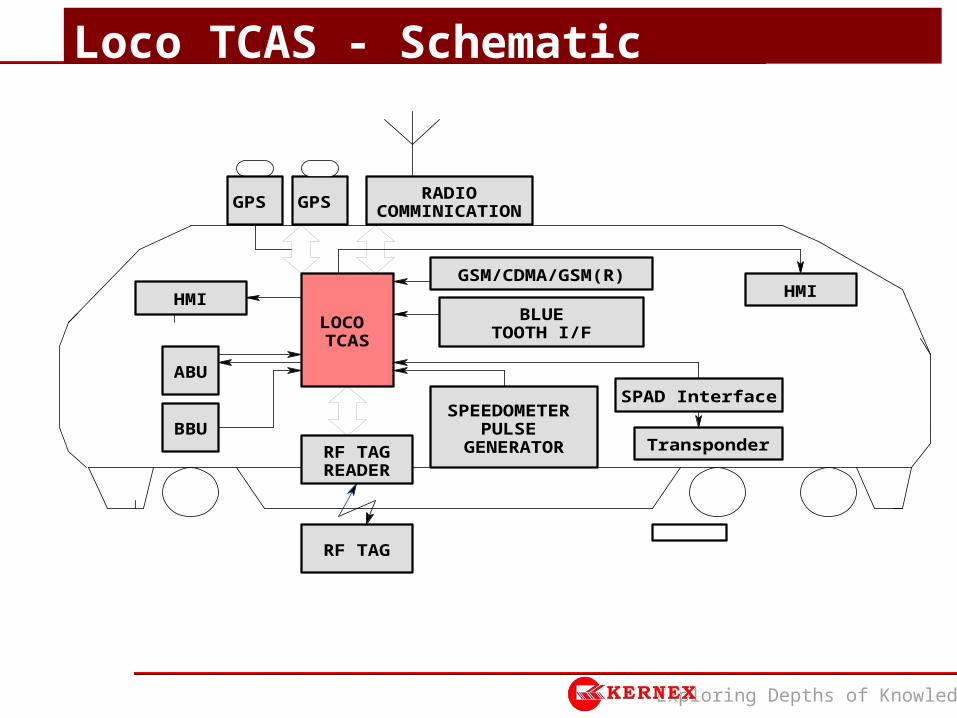
Loco TCAS - Schematic
SPEEDOMETER PULSE
GENERATORBBU
RADIOCOMMINICATIONGPS
ABU
GPS
GSM/CDMA/GSM(R)
BLUETOOTH I/F
RF TAGREADER
SPAD Interface
HMI HMI
Transponder
RF TAG
LOCO TCAS
Exploring Depths of Knowledge
• Dual Microprocessor based control system, along with dual redundant radio modems, RF Tag Readers and GPS Receivers
• Interface to the existing speedometer• Event Logging sub-system along with blue-tooth data
uploading/down loading facility and redundant GSM I/F.• Two Loco pilot Operation cum indication panel (LPOCIP) –
for Loco pilot and Asst. Loco pilot • Braking interface unit (BIU)• Dual Isolated Power Supply unit
Loco TCAS major Sub-systems

Exploring Depths of Knowledge
Loco TCAS Architecture
RS-232
PPS-1
PPS-2
RS-232
RS-485
ISO
USB
RS-232
RS-232
RS-232
RS-485
MIE-5
RFID READER-2
MIE-6
Brake Interface Unit
FOM (2 OUT OF 2 LOGIC)
FIM-1 FIM-2
MIE-1 MIE-2
RS-232
RM-1GPS
RECEIVER-1GPS
RECEIVER-2 BUS
MIE-3
RX TX RX TX
RM-2
MIE-4 LP-OCIP1 LP-OCIP2 RS-232
PSM1- 24V DC(exitation)
PSM2- 24V DC(exitation)
PSM2- Health Status
PSM1- 12V DCPSM1- 24V DC
PSM1- 5V DC PSM1- Health Status
PSM2- 5V DC
PSM2- 24V DCPSM2- 12V DC
Redundant 5V DC For EL,GSM &BT
PSM2
PSM1
DATA DOWNLOADING
EQUIPMENT
BLUE TOOTH
GSM/GPRSMODEM-1
GSM/GPRSMODEM-2
72V DCOR
110VDC
SPEEDO INPUTS(CH-1 with CH-2 Phase diff. by 90
0
CH-1
CH-1 CH-2
CH-2SPEEDOMETER
INTERFACE
PSM 3
EVENT LOGGERUSB
RFID READER-1
PHYSICALDOWNLOADING
CAN BUS2
CAN BUS1
NOTE:
1)PSM2- 5V DC For MIE-2,MIE-4,MIE-6,GPS-2, FIM-2,FOM,SPEEDOMETER 2)PSM2- 12V DC For RFID-2 3)PSM2- 24V DC For RM-2,OCIP-2 4)PSM2- 24V DC(EXITATION) For FIM-2,FOM
5) EL- Event Logger
NOTE:
1)PSM1- 5V DC For MIE-1,MIE-3,MIE-5,GPS-1, FIM-1,FOM,SPEEDOMETER2)PSM1- 12V DC For RFID-13)PSM1- 24V DC For RM-1,OCIP-14)PSM1- 24V DC(EXITATION) For FIM-1,FOM

Exploring Depths of Knowledge
Loco TCAS – Architectural Features• Two redundant Microcontrollers (MIE 1 & MIE 2) working in “2
out of 2” mode to achieve high level of safety.• All modules are connected through redundant CANBUS.• Two redundant Microcontrollers (MIE 3 & MIE 4) as
communication processors. • Two redundant Microcontrollers for peripheral interface.• Separate Event logger for major events logging and storing for
90 days.• Two UHF full-duplex Radio Communication Equipment with
hot standby and associated antennae: Frequency for Transmission by Loco : 441.8 MHz Frequency for Reception by Loco : 466.8 MHz Transmission by Loco for emergency (SOS) Communication
: 466.8MHz

Exploring Depths of Knowledge
Loco TCAS – Architectural Features ( Contd..)• Dual Redundant GPS units are interfaced with Loco TCAS to get
synchronization for TDMA as well as to act as standby when speedometer fails.
• Radio Antennae & GPS receiver antennae are permanently fixed on the rooftop of the locomotive and connected to the Loco Unit through RF cables.
• Dual Redundant RF-ID readers for finding Track Identification Number (TIN) and Absolute location.
• Dual Redundant GSM/GPRS modems for health check and transfer of failures to CMS.
• Bluetooth device for data up-loading and down loading.• USB port for Event down loading.• Loco Unit interfaced externally with Braking Interface Unit (BIU).• Multi level Braking system, with the help of a proportional valve.

Exploring Depths of Knowledge
Loco Pilot Operation cum Indication Panel• Two LP-OCIPs (Operation cum Indication Panel) provided for
Loco pilot and Asst. pilot interaction with TCAS.
• Functions performed: 1. Speed indication in analog and digital forms2. Display of immediate signal aspect3. Target distance and movement authority in meters4. Generation of SOS5. Selection of Leading/ Non leading of loco6. Light engine/ Formation selection7. Display of system health

Exploring Depths of Knowledge
Loco Pilot Operation cum Indication Panel

Exploring Depths of Knowledge
Breaking Interface Unit (BIU )
• Based on Proportionate Valve – Brake pipe pressure will be proportional to the input voltage
• Separate Light engine brake• Separate Dedicated valve for emergency brake• Does not interfere with the brake action of the Loco Pilot• No continuous leakage of air after achieving the required
pressure..

Exploring Depths of Knowledge
RF Tag placement in Station
To be provided by Ajaiah

Exploring Depths of Knowledge
Station TCAS major Sub-systems
• Dual Microprocessor based control system, along with dual redundant radio modems and GPS Receivers
• Event Logging System along with blue-tooth data uploading /down loading facility and redundant GSM Interface and OFC Interface.
• Station Master operation cum indication panel• Station yard layout and status panel (21”)• Dual Redundant Power Supply unit• Battery and Battery charger• 30 meter Tower for radio modem.

Exploring Depths of Knowledge
Station TCAS Architecture
CAN BUS2
RS-232
RS-232
PPS-1
RS-232
CAN BUS1
USB
USB
RS-232
RS-232
RS-232
BUS
FOM(2 OUT OF 2 LOGIC)
FIM-1 FIM-2
MIE-1 MIE-3
RM-1
RS-232
GPS RECEIVER-1
GPS RECEIVER-2
PPS-2
RM-2
21"LCD
MP/MCSM-OCIPMIE-4
EVENT LOGGER
GSM/GPRSMODEM-1
GSM/GPRSMODEM-2
DATA DOWNLOADING
EQUIPMENT
BLUE TOOTHPHYSICAL
DOWNLOADING
BATTERY CHARGER
CUM POWER SUPPLY
BATTERY
PSM1
PSM2
PSM3
230V AC
24V DC
PSM3- 5V DC For
GSM,EL,BT
PSM1- 5V DCPSM1- Health Status
PSM1- 24V DC
PSM1- 24V DC(EXITATION)
PSM2- 24V DC(EXITATION)
PSM2- 5V DC
PSM2- Health Status
PSM2- 24V DC
RX TX RX TX
NOTE:
1)PSM1- 5V DC For MIE-1,MIE-3,GPS-1, FIM-1,FOM2)PSM1- 24V DC For RM-1,OCIP3)PSM1- 24V DC(EXITATION) For FIM-1,FOM
NOTE:
1)PSM2- 5V DC For MIE-2,MIE-4,GPS-2, FIM-2,FOM2)PSM2- 24V DC For RM-23)PSM2- 24V DC(EXITATION) ForFIM-2,FOM
MIE-2
Exploring Depths of Knowledge
Station TCAS Architectural Features• Two Microcontrollers (MIE 1 & MIE 2) working in “2 out of 2”
mode to achieve safety of desired functionality.• All modules are connected through redundant CANBUS.• Two redundant Microcontroller (MIE 3 & MIE 4) working on
for radio communication and display. • Event logger for major event logging and storage for 30 days• Two UHF full-duplex Radio Communication Equipment with
hot standby and associated antennae Frequency of Transmission by Station : 466.8 MHz Frequency of Reception by Station: 441.8 MHz
• Two GPS units are interfaced with Station TCAS• Radio Antennae & GPS receiver antennae are permanently
fixed on the preinstalled 30 mtr towers. • Two GSM/GPRS modems for transfer of failures to CMS.

Exploring Depths of Knowledge
Station TCAS Architectural Features ( Contd..)• Station-OCIP (Operation cum Indication Panel) provided for station master.
• Existing fail safe signal, point status relay interface contact input reading.
• 21’’ LCD monitor for yard display.
• Bluetooth device for data Transfer.
• Battery with battery charger cum power supply to provide up to 24 hrs.
Exploring Depths of Knowledge
IBS/LC TCAS
• Intermittent block Station/ Level crossing gate TCAS is similar to Station TCAS Unit, but with less no. of Inputs / outputs.
• No user interface
• Acts like a base station

Exploring Depths of Knowledge
Centralized Management System
Station A Station B Station C Station N
Loco 2
GSMNetwork
Loco 3
Loco 1
CentralManagement
System
LAN Network
Railnet
WebReports
WebReports

Exploring Depths of Knowledge
Station/IBS/LC TCAS - Schematic
I/P fromInterlocking
Central Unit
RadioComm Rec
.... ....
GPSRec
GPS Antinna
SM-OCIP

Exploring Depths of Knowledge
• RFID Tags Provided at Start/End of TCAS Territory One Kilometer on Straight Track At Turnouts to detect diversions and Infringements Block Entry – foot of Last Stop Signal Station Entry – at the end of the Block Overlap at the
Station Foot of Signal
• Each Location with Pair of Tags for Redundancy• Rigid Fixture with Clamps on Sleepers
Trackside RFID Tags

Exploring Depths of Knowledge
TCAS
System Functions

Exploring Depths of Knowledge
•In-Cab Signaling•Detection and Prevention of SPAD•Display of Distance of Signal and Movement
Authority•Loop Line Speed Control•Speed Control at PSR/TSR
ATP Functions
Exploring Depths of Knowledge
• Prevention of Head-On Collision• Prevention of Rear-End Collision• Prevention of Collision due to Unusual Stoppage in
Block Section• Detection of Train Parting with External Input• Manual SOS Generation Feature in Station TCAS• Manual SOS Generation Feature in Loco TCAS• Detection of Roll back
Collision Prevention Scenarios

Exploring Depths of Knowledge
• Full Duplex Radio Communication• Location with RFID and Existing Tachometer• Automatic and Manual Brake Test • No Database in Locomotive TCAS Unit• Automatic Train Length Measurement Feature• Station to Station Communication for Additional Layer
Block Protection
Supporting Functions

Exploring Depths of Knowledge
Modes of Operations
• Normal Mode• Controlled Mode (when any vital system fails)• Restricted Mode (15 Kmph operation)• Staff Responsible mode (Manual mode)• Coupled / banking operation• Trip and Post Trip Modes• On-Sight Mode• Reverse Mode (to move in reverse direction)• Shunting mode

Exploring Depths of Knowledge
Features of TCAS • Full Duplex Radio Communication• Location determination with RFID and existing Tachometer• Automatic and Manual Brake Test • No Database in Locomotive TCAS Unit ; hence operation,
handling of yard layout changes will be easy.• Automatic Train Length Measurement Feature• Station to Station Communication for Block Protection (as
additional layer) • Time synchronization of complete network through GPS

Exploring Depths of Knowledge
Features of TCAS ( Contd..)
• Handling of New Train Formation• RFID based Track Id & Location Determination• Multi Level Braking Interface• Provision of Controlled Mode (Manual mode) Operation• TDMA based Communication protocol• Startup/Online Diagnostics• Event Logging • Central Monitoring through GSM / GPRS network for
maintenance• Data up-loading & down loading through ‘Bluetooth’.

Exploring Depths of Knowledge
Environmental Specifications • Operating Temperature: -10 to +70 deg. C• Relative Humidity : 95% (non-condensing)• Vibration : 3 g for Loco; 2 g for Station & LC• Mechanical Shock : 20 g peak for 11 msec. (non-operating)• Bump : 40 g peak in packed conditions• MTBF (Planned)
- Loco unit: 20,000 hrs - Station Unit: 60,000 hrs

Exploring Depths of Knowledge
Present Status • Installed Station TCAS in Nawandgi and Kurukunta stations• Installed Loco TCAS in one electric and one diesel loco• KMIL participated in several field trials to study / verify
• Radio communication• RFID readers and tags• Inter-operability with other vendors equipment between
stations Tandur, Mantatti, Nawandgi and Kurukunta. • Various control logics including SPAD
• Prototype testing completed. (Same was used for site trials since Jan 14.)
• Independent Safety assessor (ISA) clearance for Hardware design completed.

Exploring Depths of Knowledge
Present Status ( Contd..)
• System documents under review by ISA.• Soil test for Tower erection completed.• Approval for Tower locations in stations and LCs from SCR obtained.• Tower design with CPRI approval completed.• Relay room wiring in Station- approval from SCR obtained.• Unit level manufacturing in progress.• Software documents under review by ISA.• Software Functional logics developed and tested during site trials.

Exploring Depths of Knowledge
TCAS
Scenarios

Exploring Depths of Knowledge
• Approaching Signal Aspect is Transmitted by Station TCAS to Loco TCAS
• Loco TCAS Displays Signal Aspect on LP-OCIP• In case Driver fails to apply brakes to reduce the speed/stop
the train, TCAS Applies brakes to stop the train. • On Change of Signal Aspect to green, brakes will be released
Detection & Prevention of SPAD

Exploring Depths of Knowledge
• Station TCAS gets inputs from Signaling and transmits the same to the approaching Loco TCAS
• The Signal Aspect of the next approaching signal is displayed on the LP-OCIP
• Movement authority is also displayed along with the signal aspect on the LP-OCIP
• On Crossing the Signal, Next Signal Aspect and Movement authority is automatically updated on the LP-OCIP
In Cab Signaling

Exploring Depths of Knowledge
Display of Signal & Movement Authority

Exploring Depths of Knowledge
• Station TCAS gets inputs from Signaling and transmits the route Information to the approaching Loco TCAS
• In case the route is set to Loop Line and the Loco Pilot does not apply brakes to achieve speed limit, Loco TCAS applies brakes to regulate to the Loop Line speed Limit
• If Loco Pilot applies brakes, then Loco TCAS will not apply brakes as speed is monitored dynamically
Loop Line Speed Control

Exploring Depths of Knowledge
• Two trains approach each other in Block section on the same Track is sensed.
• Station TCAS Transmits the HOC Condition to both Locos• Both Locos individually deduce HOC Condition based on
Emergency Broadcast• Brakes are applied to both the Locos and brought to a stop
Prevention of Head-On Collision

Exploring Depths of Knowledge
• Two trains approach each other in Block section on the same Track is sensed.
• Station TCAS Transmits the REC Condition to both Locos• Both Locos individually deduce REC Condition based on
Emergency Broadcast• Brakes are applied to the Rear Loco and brought to a stop
Prevention of Rear-End Collision

Exploring Depths of Knowledge
• One Train Stopped in Block Section either due to Derailment or for any other Reason is sensed by Station TCAS
• Station TCAS Transmits the Unusual Condition to the other Loco entering the Block Section
• Unusual Stoppage Emergency Broadcast also is sensed by the approaching Loco
• Brakes are applied to the Approaching Loco and regulates to 15 Km/h• In case there is no obstruction, Loco Pilot can increase the speed
after crossing the stopped Train
Unusual Stoppage in Block Section

Exploring Depths of Knowledge
• There is a provision on SM OCIP for generating emergency condition
• SM can Press the Manual SOS buttons• All trains within the range of 3000m applies EB and stops• Loco Pilots of the trains can press the Manual Override and
pilot the train at 15 Km/h• On Cancellation of Manual SOS in the Source Loco, Speed
restriction is removed
Manual SOS from Station

Exploring Depths of Knowledge
• There is a provision on LP OCIP for generating emergency condition
• Loco Pilot can Press the Manual SOS buttons• All trains within the range of 3000m applies EB and stops• Loco Pilots of other the trains can press the Manual Override
and pilot the train at 15 Km/h• On Cancellation of Manual SOS in the Source Loco, Speed
restriction is removed
Manual SOS from Loco

Exploring Depths of Knowledge
• Using External Sensor for Train Parting, Loco TCAS detects train parting condition
• Train Parting Message is sent to the Station TCAS as well as transmitted in the Emergency Communication Slots
• Any Loco TCAS approaching the Parted Loco TCAS applies brakes to regulate the speed to 15 km/h
• Driver can look out for infringement and can go at full speed on crossing the Parted Train
Prevention of Collision due to Train Parting

Exploring Depths of Knowledge
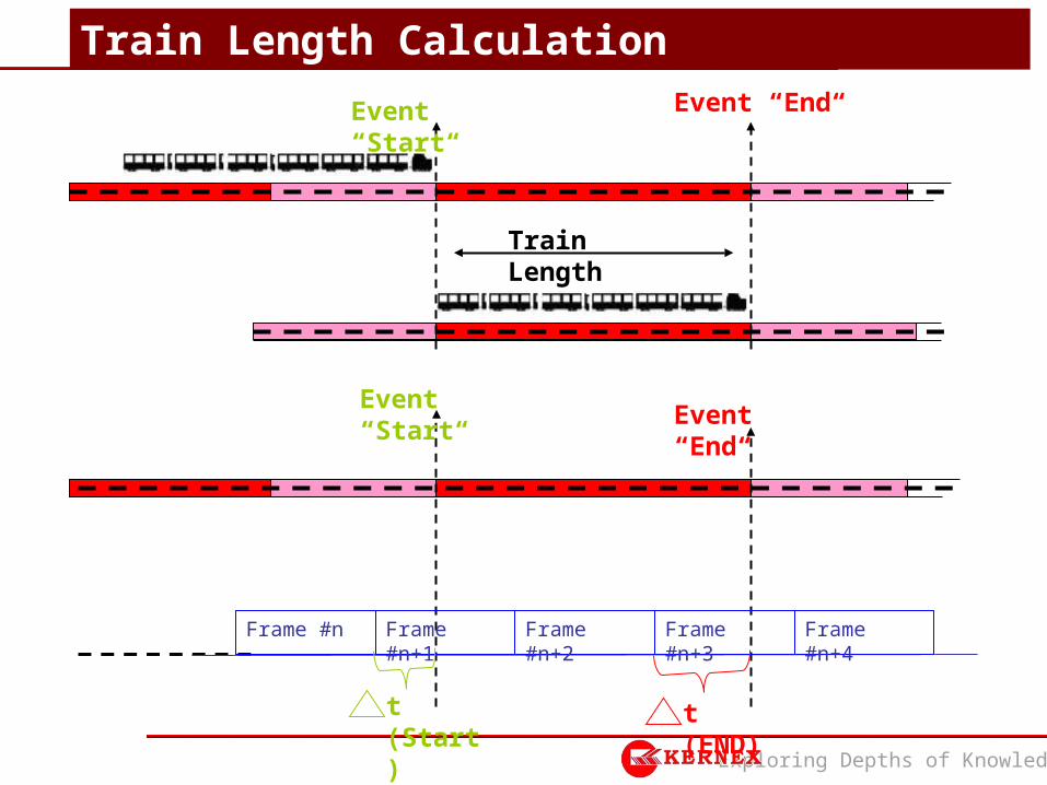
• Loco Unit Stores its position and speed in FIFO• Station TCAS transmits the Start marker time stamp T1 to
Loco TCAS (in millisecond accuracy)• Station TCAS transmits the End marker time stamp T2 to the
Loco TCAS (in millisecond accuracy)• Based on the start and end time and the speed at which Loco
is traveling, Loco TCAS calculates the Train Length
Train Length Calculation
Exploring Depths of Knowledge
Train Length
Event “Start“ Event “End“
Event “Start“Event “End“
Frame #n+2Frame #n Frame #n+3 Frame #n+4Frame #n+1
t (Start) t (END)
Train Length Calculation

Exploring Depths of Knowledge
• When Loco reaches a speed of more than 50 Km/h and is accelerating, Loco TCAS applies NB through Braking Interface Unit (BIU)
• Speed is reduced by 20 Km/h• Based on the time taken, Deceleration constant (DC) of the
train is calculated and stored for any future brake application. • Default DC is taken as 0.2 m/s2
• Calculated DC is extrapolated for application of FSB and EB• Manual Brake Test is applied in Loco sheds to test the
functioning of BIU
Auto Brake Test & Manual Brake Test
Exploring Depths of Knowledge
TCAS
Architectural Features andSafety Certification
Exploring Depths of Knowledge
• Two redundant Microprocessors/controllers (MIE 1 & MIE 2) working in “2 out of 2” mode to achieve safety of desired functionality
• Two redundant Microprocessor/controller (MIE 3 & MIE 4) working on for radio communication and display.
• Two full-duplex Radio Modems with hot standby and associated antennae
• One GPS unit is interfaced with Loco TCAS to get time synchronization for TDMA as well as to act as standby when speedometer fails.
• Radio Antennae & GPS receiver antennae are permanently fixed on the rooftop of the locomotive and connected to the Loco TCAS through RF cables.
TCAS Architectural Features

Exploring Depths of Knowledge
• Interfaced with two RF-ID readers for finding Track ID. • Interfaced with two GSM/GPRS modems for transfer of
failures to CMS.• Interfaced with two LP-OCIP’s (Operation cum Indication
Panel) which are mounted on the Driver’s pedestal for easy access and visibility to the Driver.
• Interfaced with Bluetooth device for data Transfer. • Loco TCAS interfaced externally with Automatic Braking Unit
(ABU) for Normal Brake, Full Service Brake and Emergency Brake
• Interfaced with 2 Field Input Modules (FIM) for Inputs. • Interfaced with 2 Field output Modules (FOM) for outputs.
TCAS Architectural Features Contd..

Exploring Depths of Knowledge
• Loco TCAS interfaced with existing odometer’s pulse generator to compute location data.
• Loco TCAS also interfaces with Inter-Cock Switch (ICS) to determine coupling / banking mode of train operations
• Logging of eventlogs by eventlog module, which can be downloaded through Bluetooth.
• 1 Battery with battery charger to provide up to 30 min power backup.
• 2 Hot Standby redundant power supply modules to provide power supply to all the modules of Loco TCAS Unit
TCAS Architectural Features Contd..

Exploring Depths of Knowledge
• Independent Safety Assessor (ISA) done by ERTL, Kolkata• Hardware Design is Verified to provide required Safety• Software Design is Verified to provide required Safety• System is Validated Independently to ensure proper
functionality• Design and Safety Documents are Verified to meet required
Safety Level• On completion of assessment, Certification is done
Safety Certification
Exploring Depths of Knowledge
TCAS
Radio Communication

Exploring Depths of Knowledge
• Full Duplex Communication• Stationary Units Transmit on Frequency ‘F1’ and Receive on
‘F2’• Locomotive Units Transmit on Frequency ‘F2’ and Receive on
‘F1’• In Emergency Situations, Loco Units also transmit in ‘F1’ and
tune back to ‘F2’ for Listen. • Uses Time Division Multiplexing (TDMA) for Communication
Radio Communication

Exploring Depths of Knowledge
Tx by Stationary (f1)
Tx by Train (f2)
Tx by Train
( Addl SOS/ Emergency Tx)
(f1)
MR3 MR4 ME4ME3
30
4
30
4
30
4
30
4
49
6
49
6
49
6
30
4
30
4
30
4
30
4
48
96
96
M1
M5
M39
M40
M44
M45
M53
M54
M62
M63
M71
M72
M76
30
4
30
4
30
4
30
4
30
4
30
4
30
4
30
4
30
4
30
4
30
4
49
6
49
6
48
96
96
96
96
2704 Bits
MTP
48
30
49
6
96
30
4
1094 Bits ( Repeater/End
Cabin)9
6
S1 S9
48
3504 Bits3
04
S5
S6 S7 S8
1094 Bits ( Repeater/End
Cabin)
3504 Bits
3504 Bits
3504 Bits9
6
96
96
96
49
6
49
6
49
6
49
6
49
6
30
4
30
4
30
4
30
4
Timeslot Position Marker
1 2 3 7 55 56 66 68 72 75 8645 46 79 81
S4
Communication Time Frame

Exploring Depths of Knowledge
TCAS
Position Determination

Exploring Depths of Knowledge
• Loco TCAS is fitted with two RF Readers. • RF Tags are fitted on the sleeper• On Crossing RF Tag, Loco TCAS gets Absolute Position• From tachometer Speed, position is accumulated• GPS is used as fall back, in case of tachometer failure• Tag Crossed + distance traveled is Transmitted to Station TCAS• Station TCAS Calculates position of Train based on Absolute
Position of Tag + Distance Traveled
Position Determination

Exploring Depths of Knowledge
Kernex Microsystems (India) Limited‘THRUSHNA’, PLOT NO 7, A.P.I.I.C LAYOUTSHI-TECH CITY, MADHAPUR, HYDERABAD – 500081Tel: +91-40-23113192-94, Fax: +91-40-23113191;URL: www.kernex.in
THANK YOU