exploring an ipv6 protocol for mobile sensor network ... · exploring an ipv6 protocol for mobile...
TRANSCRIPT

Exploring an IPv6 protocol for mobile sensor network communication
by
Weiqi Zhang
TR13-226, May 31, 2013
This is an unaltered version of the author’s MCS thesis
Faculty of Computer ScienceUniversity of New BrunswickFredericton, N.B. E3B 5A3
Canada
Phone: (506) 453-4566Fax: (506) 453-3566E-mail: [email protected]
http://www.cs.unb.ca

Abstract
This research explores IPv6 in mobile wireless sensor networks (WSNs). An indoor
WSN mobile sensor network testbed of length 24 m was built and used for mobile
WSN testing. The test network enabled the use of one or two moving nodes and six
stationary nodes. TelosB sensor nodes were used for testing.
The thesis presents a detailed explaination of sending and receiving User Datagram
Protocol (UDP) packets using the IPv6 Low Power Wireless Area Network (6LoW-
PAN) software stack in the Berkeley Low power Internet Protocol (BLIP) implemen-
tation of TinyOS 2.1.1 and 2.1.2. A Java based Web application called WSNWeb
was built that displays real-time route topology changes and sensor data. The data
is updated in a log file, and used to compute packet loss and determine the number
of route topology changes.
We created 35 test cases, 15 with two moving nodes, and 20 with one moving node.
On a test track, model train velocities between 0.076 m/s and 0.376 m/s were used,
with three different routing table update periods (RTUPs) of 60 s, 6 s, and 0.6 s. The
results show that the one moving node 0.6 seconds RTUP has significantly higher
packet loss (up to 1.4% compared to 0.16%) over a five hour test compared to RTUPs
of 60 s and 6 s. The two moving nodes test shows that RTUP of 0.6 s still has a
higher packet loss compared to RTUPs of 6 s and 60 s.
ii

Acknowledgements
Foremost, with all my sincerity I would like to thank my supervisor, Dr. Bradford
G. Nickerson for his kind support of my master’s degree study and research. Dr.
Nickerson’s guidance helped me in all the time of research and writting of my thesis.
He is very patient and was always available for help and advice.
I would like to thank my dear parents, Mr. Zhongwei Zhang and Mrs. Lifeng Gao,
for aspiring me to give my best. Although they are far away from me in China, they
never stop cheering and encouraging me. Without their financial and emotional sup-
port, I could not have imagined completing my thesis.
I would also like to thank the UNB Faculty of Computer Science for offering so many
helpful courses and providing lab equipment for my study and research.
Last but not least, I would like to thank my friends whoever near or far, for giving
me so much fun and cheering me up.
iii
Table of Contents
Abstract ii
Acknowledgments iii
Table of Contents vi
List of Tables vii
List of Figures viii
Abbreviations ix
1 Introduction 1
1.1 Wireless Sensor Networks . . . . . . . . . . . . . . . . . . . . . . . . 1
1.2 Thesis Objectives . . . . . . . . . . . . . . . . . . . . . . . . . . . . . 2
2 IPv6 in Wireless Sensor Networks 3
2.1 6LoWPAN Architecture . . . . . . . . . . . . . . . . . . . . . . . . . 3
3 Architecture and Design 7
3.1 Moving Node Software . . . . . . . . . . . . . . . . . . . . . . . . . . 7
3.2 Stationary Node Software . . . . . . . . . . . . . . . . . . . . . . . . 9
3.3 Web Application . . . . . . . . . . . . . . . . . . . . . . . . . . . . . 10
3.3.1 Server . . . . . . . . . . . . . . . . . . . . . . . . . . . . . . . 10
3.3.2 Client . . . . . . . . . . . . . . . . . . . . . . . . . . . . . . . 16
iv

4 Implementation 23
4.1 Berkeley Low-Power IPv6 Stack (BLIP) . . . . . . . . . . . . . . . . . 23
4.1.1 Sending . . . . . . . . . . . . . . . . . . . . . . . . . . . . . . 23
4.1.2 Receiving . . . . . . . . . . . . . . . . . . . . . . . . . . . . . 30
4.2 ip-driver Software Architecture . . . . . . . . . . . . . . . . . . . . . 32
4.3 IPBaseStation Software Architecture . . . . . . . . . . . . . . . . . . 38
4.4 Moving Node Software Implementation . . . . . . . . . . . . . . . . . 40
4.4.1 Define Sensors . . . . . . . . . . . . . . . . . . . . . . . . . . . 40
4.4.2 Sensor Readings Calculation . . . . . . . . . . . . . . . . . . . 42
4.4.2.1 Light Sensors . . . . . . . . . . . . . . . . . . . . . . 42
4.4.2.2 Humidity and Temperature Sensor . . . . . . . . . . 43
4.4.2.3 Voltage Sensor . . . . . . . . . . . . . . . . . . . . . 43
5 Experimental Design and Results 49
5.1 Mobile Wireless Sensor Architecture . . . . . . . . . . . . . . . . . . . 49
5.2 Experimental Testing Software Architecture . . . . . . . . . . . . . . 53
5.2.1 Packet Specification . . . . . . . . . . . . . . . . . . . . . . . . 53
5.2.2 Testing software architecture . . . . . . . . . . . . . . . . . . . 56
5.2.2.1 Detecting Packet Route Topology Change . . . . . . 56
5.2.2.2 Measuring Packet Loss . . . . . . . . . . . . . . . . . 61
5.3 What We Measured . . . . . . . . . . . . . . . . . . . . . . . . . . . . 64
5.3.1 Testing Results . . . . . . . . . . . . . . . . . . . . . . . . . . 66
5.3.1.1 One Moving Node Testing . . . . . . . . . . . . . . . 66
5.3.1.2 Two Moving Nodes Testing . . . . . . . . . . . . . . 68
6 Summary and Conclusions 72
6.1 Summary . . . . . . . . . . . . . . . . . . . . . . . . . . . . . . . . . 72
6.2 Conclusions . . . . . . . . . . . . . . . . . . . . . . . . . . . . . . . . 73
v

6.3 Future Work . . . . . . . . . . . . . . . . . . . . . . . . . . . . . . . . 73
References 76
A Moving Node Software 77
A.1 Data Structures Used in UDP Packets in Testing . . . . . . . . . . . 77
A.2 Main Program for Moving Node . . . . . . . . . . . . . . . . . . . . . 78
B Stationary Node Software 82
C Testing Software 85
C.1 Java Monitor Program . . . . . . . . . . . . . . . . . . . . . . . . . . 85
C.2 Python Monitor Program . . . . . . . . . . . . . . . . . . . . . . . . 87
D WSNWeb Application 90
D.1 Server Side Source Code . . . . . . . . . . . . . . . . . . . . . . . . . 90
D.2 Client Side Source Code . . . . . . . . . . . . . . . . . . . . . . . . . 96
Vita
vi

List of Tables
3.1 Functions of each Read interface in the module UDPMovingP. . . . . . 83.2 Methods of a connection object for the WSNWeb client. . . . . . . . . 18
4.1 TinyOS 2.1.1 interfaces and implementations for 6LoWPAN supportin BLIP. . . . . . . . . . . . . . . . . . . . . . . . . . . . . . . . . . . 39
4.2 TelosB built-in sensors used in moving node application. . . . . . . . 41
5.1 UDP payload structure. . . . . . . . . . . . . . . . . . . . . . . . . . 555.2 Speed step velocities map for train engine 6404. . . . . . . . . . . . . 655.3 Speed step velocities map for train engine 1478. . . . . . . . . . . . . 655.4 Number of topology changes (NTC) and packet loss under different
routing table update periods, and different train velocities in one mov-ing node testing. . . . . . . . . . . . . . . . . . . . . . . . . . . . . . 66
5.5 Number of topology changes (NTC) and packet loss under differentrouting table update periods, and different train velocities in two mov-ing node testing. . . . . . . . . . . . . . . . . . . . . . . . . . . . . . 69
List of Figures
2.1 IEEE 802.15.4 frame, from [20]. . . . . . . . . . . . . . . . . . . . . . 42.2 Data encapsulation. . . . . . . . . . . . . . . . . . . . . . . . . . . . . 42.3 Initial fragment of Adapt header [16]. . . . . . . . . . . . . . . . . . . 42.4 Noninitial fragment of Adapt header, from [16]. . . . . . . . . . . . . 52.5 Dual stack, integrating 6LoWPAN with IPv6, from [20]. . . . . . . . 52.6 6LoWPAN addressing, based on the description in RFC4944 [16]. . . 6
3.1 Wiring of interfaces for the UDPMoving application (adapted fromGraphviz version). . . . . . . . . . . . . . . . . . . . . . . . . . . . . 9
3.2 Architecture diagram of the WSNWeb web application. . . . . . . . . 113.3 Boot sequence of the Apache Tomcat server with embedding Jetty
server, the details of the Tomcat boot sequence is shown in [12]. . . . 12
vii
3.4 Subset of Jetty library *.jar files used to implement a WebSocketcommunication. . . . . . . . . . . . . . . . . . . . . . . . . . . . . . . 13
3.6 The file web.xml defines Listener and startup web page. . . . . . . . . 133.7 Sequence diagram of starting the thread in the constructor of Ws-
nWebSocketHandler. . . . . . . . . . . . . . . . . . . . . . . . . . . . 153.8 Defining a WebSocket object in JavaScript. . . . . . . . . . . . . . . . 173.9 Processing of route topology and sensor reading message received at
the client. . . . . . . . . . . . . . . . . . . . . . . . . . . . . . . . . . 193.5 Class diagram of the WSNWeb web application. . . . . . . . . . . . . 213.10 A screen shot of the WSNWeb application. . . . . . . . . . . . . . . . 22
4.1 UDP interface sending packets to an IP address. . . . . . . . . . . . . 244.2 Sequence diagram of sendTask(). . . . . . . . . . . . . . . . . . . . . 254.3 Sequence diagram of getNextFrag(). . . . . . . . . . . . . . . . . . . . 264.4 Picture of the edge router with connected USB Raven and gateway. . 274.5 A complete UDP packet captured in Wireshark. . . . . . . . . . . . . 284.6 The first fragment of the UDP packet in Figure 4.5. . . . . . . . . . . 294.7 The subsequent fragment of the UDP packet in Figure 4.5. . . . . . . 294.8 The implementation of receive() event. . . . . . . . . . . . . . . . . 314.9 How BLIP handles first fragment when a node receives it. . . . . . . . 324.10 Dual stack, integrating 6LoWPAN with IPv6, adapted from [20]. . . . 334.11 Wireless sensor network architecture in ITB214. . . . . . . . . . . . . 344.19 read and process reads and processes up to one 6LoWPAN packet. . 364.21 Sequence diagram of reassembly when serial port receives 6LoWPAN
packets. . . . . . . . . . . . . . . . . . . . . . . . . . . . . . . . . . . 384.22 Transmission of packets from radio to uart. . . . . . . . . . . . . . . . 404.23 Transmission of packets from uart to radio. . . . . . . . . . . . . . . . 404.12 Sequence diagram of setting up TCP socket and tunnel interface in
the ip-driver program. . . . . . . . . . . . . . . . . . . . . . . . . . 444.13 Sequence diagram of opening a serial port and initializing routing in
ip-driver. . . . . . . . . . . . . . . . . . . . . . . . . . . . . . . . . . . 454.14 Sequence diagram of tunneling process of receiving data. . . . . . . . 464.15 Sequence diagram of tun input(). . . . . . . . . . . . . . . . . . . . 464.16 Sequence diagram of serial input(). . . . . . . . . . . . . . . . . . 474.17 Definition of data type serial source t. . . . . . . . . . . . . . . . . 484.18 Definition of data type packed lowmsg t. . . . . . . . . . . . . . . . . 484.20 Definition of data type reconstruct t. . . . . . . . . . . . . . . . . . 48
5.1 Model train running on the wireless sensor network testbed in ITB214. 495.2 A Telosb node is carried on the model train. . . . . . . . . . . . . . . 505.3 General view of train track in ITB214. . . . . . . . . . . . . . . . . . 515.4 Model railroad track in ITB214. . . . . . . . . . . . . . . . . . . . . . 525.5 Model railroad track corner. . . . . . . . . . . . . . . . . . . . . . . . 535.6 Packet structure of UDP over IPv6. . . . . . . . . . . . . . . . . . . . 545.7 141 bytes Payload structure. . . . . . . . . . . . . . . . . . . . . . . . 54
viii
5.8 Packet specification of field sensor reading. . . . . . . . . . . . . . . . 565.9 Monitor.java monitors the topology changes of the network, and
UDPMonitor.py stores all the received UDP packets and calculatespacket loss. . . . . . . . . . . . . . . . . . . . . . . . . . . . . . . . . 56
5.10 A sample response to the routes command. . . . . . . . . . . . . . . 575.11 Message passing between Monitor and ip-driver. . . . . . . . . . . 605.12 A portion of a sample route info.log file. . . . . . . . . . . . . . . . 605.13 Measuring packet loss. . . . . . . . . . . . . . . . . . . . . . . . . . . 645.14 Sample output from the UDPMonitor program. Line 1262 shows the
141 byte payload for a received UDP packet. The first two bytes (1,158) are the high and low parts of the sequence number, which is1× 256 + 158 = 414. . . . . . . . . . . . . . . . . . . . . . . . . . . . 64
5.15 Packet loss vs. train velocity for one moving node testing. . . . . . . . 675.16 Number of topology changes vs. train velocity for one moving node
testing. . . . . . . . . . . . . . . . . . . . . . . . . . . . . . . . . . . . 685.17 Packet loss vs. train velocity for two moving nodes testing. . . . . . . 705.18 Total packet loss vs. train velocity for two moving nodes testing. . . . 705.19 Number of topology changes vs. train velocity for two moving node
testing. . . . . . . . . . . . . . . . . . . . . . . . . . . . . . . . . . . . 71
ix

List of Abbreviations
AHM Airplane Health ManagementBLIP Berkeley Low-Power IP stackCRC Cyclic Redundancy CheckEUI Extended Unique IdentifierGHz GigaHertzHC Header CompressionHTML5 HyperText Markup Language 5HTTP Hypertext Transfer ProtocolICMP Internet Control Messasge ProtocolIEEE Institute of Electrical and Electronics EngineersIP Internet ProtocolIR InfraredJMRI Java Model Railroad Interfacejs JavaScriptkB kilo BytesLQI Link Quality IdentifierMAC Media Access ControlMHz MegaHertzMTU Maximum Transmission UnitNTC Number of Topology ChangesPAN Personal Area NetworkPL Packet LossRAM Random Access MemoryR/T Received/TransmittedRTUP Routing Table Update PeriodSI International System of UnitsTCP Transmission Control ProtocolTOS TinyOStun tunnelUART Universal Asynchronous Receiver/TransmitterUDP User Datagram ProtocolUNB University of New BrunswickUSB Universal Serial Busws WebSocketWSN Wireless Sensor Network
x

XML Extensible Markup Language6LoWPAN IPv6 over Low power Wireless Personal Area Networks
xi

Chapter 1
Introduction
1.1 Wireless Sensor Networks
Wireless sensor networks (WSNs) have numerous applications including environ-
mental monitoring [13], industrial monitoring [21], and security [18]. WSNs make
it possible to monitor dangerous places such as nuclear environments or extremely
high temperature environments where humans cannot be present. In environmental
monitoring, the WSN is deployed over an area where some environmental parame-
ters are monitored. In industrial monitoring, the WSN nodes can be deployed for
machinery condition-based maintenance. AHM (Airplane Health Management) [18]
is an example of security. In general, WSNs consist of spatially distributed sensor
nodes which can monitor environmental or physical conditions such as humidity,
pressure, temperature, vibration, light intensity and so on. Sometimes the positions
of nodes are fixed, but nodes can be mobile. An example of a mobile sensor node is
Zebranet, a system for wildlife tracking that focuses on monitoring zebras [15]. In
order to communicate with and control WSNs, WSN applications cannot be built in
isolation; they have to be connected to an existing network such as the Internet.
1

1.2 Thesis Objectives
In some cases sensor nodes are static, while in some cases sensor nodes are mov-
ing. The objective of this thesis is to explore a protocol for mobile sensor network
communication. This thesis will attempt to answer the following questions:
1. How well do 6LoWPAN libraries integrate with IP networks running IPv6?
2. Can an IPv6 protocol based on 6LoWPAN accommodate moving nodes?
3. If the IPv6 based protocol can accommodate moving nodes, how quickly can
it adapt to a dynamic environment?
2

Chapter 2
IPv6 in Wireless Sensor Networks
Internet Protocol Version 6 (IPv6) is the designated successor of IPv4 as the network
protocol for the Internet. There are 232 IPv4 addresses, but all of those have now
been allocated by the Internet Assignment Numbering Authority (IANA) as of Feb.
2011 [19]. To overcome this lack of addresses, IPv6 expands the IP address space
from 32 to 128 bits. IPv6 over Low Power Wireless Personal Area Networks (6LoW-
PAN [20]) makes it possible to connect WSN nodes to the Internet; every node can
have an IP address. An implementation of 6LoWPAN on TinyOS is called BLIP [3]
(the Berkeley Low-Power IP stack) has been already carried out by the University
of California, Berkeley.
2.1 6LoWPAN Architecture
6LoWPAN allows IPv6 packets to be sent to or received from IEEE 802.15.4-based
networks [7]. The IEEE 802.15.4 frame size is 127 bytes. Figure 2.1 shows an IEEE
802.15.4 frame. As we can see, there is space for only 31 bytes of data. The size of
an IPv6 frame is at least 1280 bytes [17]. How can we fit an IPv6 frame into an IEEE
802.15.4 frame? The solution is fragmentation. The data is first encapsulated by an
3

IPv6 header, and then encapsulated by an Adapt header, which contains fragment
information, and lastly by a MAC header. The encapsulation is shown in Figure 2.2
for UDP packets. TCP packets have a longer header (20, 24, or 28 bytes). Figure 2.3
shows the first fragment of the Adapt header, Figure 2.4 shows a noninitial fragment
of the Adapt header.
Figure 2.1: IEEE 802.15.4 frame, from [20].
Figure 2.2: Data encapsulation.
Figure 2.3: Initial fragment of Adapt header [16].
The layers of 6LoWPAN networks are shown in Figure 2.5. The packet is adapted to
6LoWPAN packet in the 6LoWPAN adaptation layer of 6LowPAN networks. In the
gateway (usually a router), the frames are adapted to IEEE 802.15.4 frame. After
converting to IEEE 802.15.4 frame, the packet can be transmited into high speed
networks (such as Internet).
The space left for data is already very small. If the Adapt header is introduced,
the space will become smaller, i.e. 28 or 29 bytes. To guarantee efficiency, the IPv6
header must be compressed.
4

Figure 2.4: Noninitial fragment of Adapt header, from [16].
Figure 2.5: Dual stack, integrating 6LoWPAN with IPv6, from [20].
Hui et al. [14] define an encoding format for 6LoWPAN called LOWPAN IPHC.
LOWPAN IPHC assumes the following will be the common case for 6LoWPAN:
1. Version is 6.
2. Traffic label class and flow label are both zero.
3. Payload length can be inferred from low layers.
4. Hop limit will be set to a well-known value by the source.
5. Addresses assigned to 6LoWPAN prefix will be formed using the link-local
prefix or a small set of routable prefixes assigned to the entire 6LoWPAN.
6. Addresses assigned to 6LoWPAN interfaces are derived directly from either the
64-bit extended or 16-bit short IEEE 802.15.4 MAC addresses [14].
5

This results in the IPv6 40 bytes header being reduced to 2 bytes.
An IPv6 address consists of two parts: the first part is a 64 bit prefix, the second part
is a 64 bit interface ID. The prefix is formed using the link-local address fe80::/64
(this notation means the first 16 bits are fe80, followed by 48 zeroes) [16]. The
interface ID is derived from the MAC address. 16 bits fffe follow the first 24 bits
of the MAC address, which are then followed by the remaining 24 bits of the MAC
address. IEEE 802.15.4 has two forms of MAC address, 64-bit EUI-64 (Extended
Unique Identifier-64) and 16-bit short addresses. If the MAC address uses a 64-
bit long address, the 6LoWPAN interface ID directly uses the MAC address as its
interface ID. If the MAC address uses a 16-bit short address, the 6LoWPAN interface
ID first uses the 16-bit short address and PAN ID (Personal Area Network Identifier)
to generate a 48-bit pseudo MAC address. Then the interface ID is derived from
this pseudo MAC address as discussed above. The 6LoWPAN address is shown in
Figure 2.6.
Figure 2.6: 6LoWPAN addressing, based on the description in RFC4944 [16].
6
Chapter 3
Architecture and Design
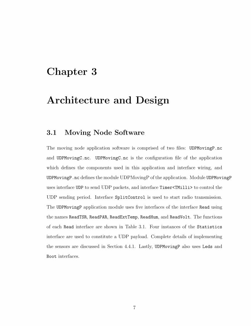
3.1 Moving Node Software
The moving node application software is comprised of two files: UDPMovingP.nc
and UDPMovingC.nc. UDPMovingC.nc is the configuration file of the application
which defines the components used in this application and interface wiring, and
UDPMovingP.nc defines the module UDPMovingP of the application. Module UDPMovingP
uses interface UDP to send UDP packets, and interface Timer<TMilli> to control the
UDP sending period. Interface SplitControl is used to start radio transmission.
The UDPMovingP application module uses five interfaces of the interface Read using
the names ReadTSR, ReadPAR, ReadExtTemp, ReadHum, and ReadVolt. The functions
of each Read interface are shown in Table 3.1. Four instances of the Statistics
interface are used to constitute a UDP payload. Complete details of implementing
the sensors are discussed in Section 4.4.1. Lastly, UDPMovingP also uses Leds and
Boot interfaces.
7

Table 3.1: Functions of each Read interface in the module UDPMovingP.
Name Function
ReadTSR Read IR sensor readings
ReadPAR Read visible sensor readings
ReadExtTemp Read temperature sensor readings
ReadHum Read humidity sensor readings
ReadVol Read voltage sensor readings
TinyOS developers use the Nesdoc tool to displays the structure and composition of
nesc applications. For example, to show the structure of an TinyOS application that
uses BLIP, we issue the following command:
make telosb blip docs
With the docs argument, the make command automatically generates a /doc/nesdoc
subdirectory. The nesdoc subdirectory contains .dot files used by Graphviz [5] to
generate a component graph. The component graph generated for our UDPMovingP
module is shown in Figure 3.1. Single line boxes represent modules, double line boxes
represent configurations, and edges are labeled with interface names. Dashed double
line boxes indicate generic components.
8

Figure 3.1: Wiring of interfaces for the UDPMoving application (adapted fromGraphviz version).
The moving node application sends UDP packets from port 7001 to destination
fec0::64 port 7000. The timer is fired every ten seconds. Every time the timer
is fired, the application reads sensors and fills the payload of the UDP packet, and
sends out the UDP packet.
3.2 Stationary Node Software
The stationary node application software consists of two files: UDPStationaryP.nc
and
UDPStationary.nc. UDPStationary is adpated from UDPMoving, the difference is
9

that
UDPStationary does not read sensors and send any UDP packets when the timer is
fired, but it does transmit 6LoWPAN packets.
3.3 Web Application
We wrote a Java-based web application called WSNWeb that monitors the topology
of the wireless sensor network. The WSNWeb application implements an embedded
Jetty server [4] comprised of two Java programs called
WsnServerServletContextListener.class and
WsnWebSocketHandler.class as shown in Figure 3.2. The Listener and Handler
manage HTTP requests and WebSocket requests, respectively. The server side code
creates a TCP socket to ip-driver through port 6106, and gets new wireless sensor
network topology when the topology changes. The client side code displays new
routes information in text form and draws network topology using the HTML5 Can-
vas element [6]. The WSNWeb server and clients (web browsers) communicate via
the Jetty WebSocket Handler component (see the next section) [9].
3.3.1 Server
Figure 3.3 shows the boot sequence of the Apache Tomcat [1] server with an embed-
ded Jetty server. We use Jetty 8.1.8.v20121106, which is the latest stable version
of the Jetty server. To use Jetty WebSocket, some Jetty libraries need to be im-
ported into the Eclipse project, as illustrated in Figure 3.4. As shown in Figure 3.5,
class WsnWebSocketHandler is a subclass of WebSocketHandler, which handles Web-
Socket requests. When this handler is registered in the Jetty Server instance, the
client side JavaScript code creates a WebSocket connection to the server, in this ex-
10

Figure 3.2: Architecture diagram of the WSNWeb web application.
ample, whose address is 131.202.243.6 on port 8081, with protocol ws (WebSocket).
The public method doWebSocketConnect() returns a WsnWebSocket instance when
a new WebSocket connection comes in.
As shown in Figure 3.5, WebSocket is a Java interface, and we need to create a class to
implement it to instantiate a WebSocket object. WebSocket has some internal inter-
faces, and we chose one to implement. Text messages are used to transmit routes in-
formation in the WSNWeb application, so we implement a WebSocket.OnTextMessage
interface inside class WsnWebSocketHandler using the following statement:
private class WsnWebSocket implements WebSocket.OnTextMessage
11

Figure 3.3: Boot sequence of the Apache Tomcat server with embedding Jetty server,the details of the Tomcat boot sequence is shown in [12].
There are three methods we need to implement in class WsnWebSocket, including
onOpen(), onMessage(),and onClose().
onOpen() is called when a client WebSocket opens a connection, and we store the new
opened connection in the set of WsnWebSocket items. onMessage() is called when
a message comes in from a client, and onClose() is called when a client WebSocket
closes, and we remove the WsnWebSocket object from the set of WsnWebSocket.
The WSNWeb web application relies on a file called web.xml located at
WSNWeb/WebContent/WEB-INF/web.xml. The file web.xml is shown in Figure 3.6,
file wsn.html is defined to be invoked on startup, and is invoked when a client opens
the WSNWeb application.
12

Figure 3.4: Subset of Jetty library *.jar files used to implement a WebSocket com-munication.
Figure 3.6: The file web.xml defines Listener and startup web page.
WsnServerServletContextListener is set to be the class that responds to
13

ServletContext event such as initialized and destroyed.
Class WsnServerServletContextListener implements interface
javax.servlet.ServletContextListener in the file
WsnServerServletContextListener.java, as follows:
public class WsnServerServletContextListener implements ServletContextListener
The ServletContextListener interface is responsible for receiving notification events
about ServletContext lifecycle changes. When the web application initialization
process is starting, contextInitialized() is called. When the ServletContext
is about to be shut down, contextDestroyed() is called. The Jetty server in-
stance is created in contextInitialized() (see Figure 3.3), and an instance of
WsnWebSocketHandler is registered to the Jetty server instance. All the HTTP
requests are processed on port 8080 using Apache Tomcat Server (e.g. display-
ing HTML files), and all the WebSocket requests are processed on port 8081 using
the embedded Jetty server (e.g. sending topology change messages to client web
browsers).
The thread that creates a TCP socket to ip-driver connection, and monitors the
network topology is created in the constructor of class WsnWebSocketHandler. The
thread starts when an instance of WsnWebSocketHandler is instantiated in
WsnServerServletContextListener. Figure 3.7 shows the code structure of start-
ing the thread. The thread keeps getting the network topology from the created
TCP socket. If there is a route change, the thread will send the new route to all
clients connected to the server through WebSocket.
14

Figure 3.7: Sequence diagram of starting the thread in the constructor of WsnWeb-SocketHandler.
The destination of UDP packets is fec0::64 on port 7000. Another thread called
udpSocketThread that creates a UDP socket to fec0::64 on port 7000 is also created
in the constructor of class WsnWebSocketHandler. udpSocketThread reads sensor
readings contained in the UDP packets, and sends sensor readings to clients. As de-
scribed in Section 5.2.1, the payload of each UDP packet used in the testing is of size
141 bytes, so we use a 141-byte buffer to receive UDP packets in udpSocketThread.
The sender address is the first 3rd and 4th bytes, light is the 14th and 15th bytes,
temperature is the 18th and 19th bytes, humidity is the 20th and 21st bytes, and
voltage is the 22nd and 23rd bytes. Each byte in a UDP packet is an 8-bit unsigned
integer, but in Java the byte data type is an 8-bit signed two’s complement integer.
We need to convert each 8-bit unsigned integer to its two’s complement representa-
tion to get the original sensor reading value. A positive integer’s two’s complement
representation is the integer itself, and an integer in Java is four bytes long. We first
cast byte to Java data type int, and then perform a bit-wise and (&) with 0xff to
reset the first 24 bits of the resultant integer. The complete Java code for converting
15

sensor readings is given in Appendix D.1.
As an example, the binary representation of unsigned integer 156 is 10011100. If we
interpret these bits as a two’s complement integer, the decimal value is -100. The
Java statement (int)recvByte[14] & 0xff converts the unsigned integer at byte
offset 14 from the recvByte array into a 4-byte integer. After conversion, thread
udpSocketThread calculates the actual environmental values based on the sensor
readings and broadcasts the actual environmental values to all clients. The details
of the calculation of actual environmental values are discussed in Section 4.4.2.
3.3.2 Client
The client side code is written in JavaScript. File Util.js contains a HashMap
class, and file jsgl.min.js contains the code of the JSGL library. JSGL is an open
source, browser independent 2D vector graphics library for JavaScript [8]. Animation
such as moving nodes and network topology updating is created using JSGL. The
JavaScript inside of the wsn.html body manages the WebSocket connection and
message processing. Our WSNWeb server creates an embedded Jetty server on port
8081, and an instance of WsnWebSocketHandler is registered to the Jetty server
instance. A WebSocket connection is available at ws://131.202.243.6:8081, where
ws:// stands for the WebSocket protocol. Clients process all the HTTP requests
through
http://131.202.243.6:8080/WSNWeb, and the JavaScript code inside of wsn.html
connects to the Jetty server and receives messages through
ws://131.202.243.6:8081. A WebSocket object is created in the client by the
definition shown in Figure 3.8.
16

Figure 3.8: Defining a WebSocket object in JavaScript.
The WebSocket connection request is sent using TCP. Once the server recieves a
WebSocket connection request from a client, the server side class
WsnServerServletContextListener calls doWebSocketConnect(), which returns a
new WsnWebSocket object to handle WebSocket events. At this point, the client
WebSocket has opened a connection, and onOpen() of WsnWebSocket is called. A
WebSocket.Connection interface is passed to the newly created WsnWebSocket ob-
ject via onOpen(), and
WebSocket.Connection has methods for sending messages (e.g. sendMessage()).
The receiving of messages is handled by method onMessage().
In the JavaScript code inside of wsn.html, an object called connection handles
WebSocket connections, message processing, and data display on the web page. Ta-
ble 3.2 shows the methods of a connection object. Figure 3.9 illustrates how both
message types (i.e. topology changes and sensor readings) are received at the client.
17

Table 3.2: Methods of a connection object for the WSNWeb client.
Name Function
join Create WebSocket connection to theserver
onopen implementation of WebSocket onopen
method, sends “connected” to theserver when successfully connected
onmessage implementation of WebSocketonmessage method, interacts toincoming messages
onclose implementation of WebSocket onclose
method, close the established Web-Socket connection
onerror implementation of WebSocket onerror
method, display error messagessend sends messages to the server
18

Figure 3.9: Processing of route topology and sensor reading message received at theclient.
As we can see from Table 3.2, method onmessage handles incoming route topology
change and sensor reading messages. When the client receives a message from the
server, onmessage checks whether it is a route topology update message or a sensor
reading message. If the message is a route topology update message (begins with
"New", e.g. "New route for 0x1: [1.0]0x6 [1.0]0x4 [1.0]0x64"), onmessage
stores the new route in the hash map on the client side, and updates the dynamic
route topology on the web page. The route of each node (both moving node and
stationary node) is represented by a polyline, whose start point is the moving node
and end point is the edge router (0x64). After storing the new route in the hash
19

map, onmessage updates the intermediate points of each node according to the route
stored in the hash map. For example, if the route of node 0x1 stored in the hash
map is 0x6, 0x4, 0x64 after updating, the points of node 0x1’s polyline become
points that represent the positions of nodes 0x1, 0x6, 0x4, and 0x64. An instance
of jsgl.util.Animator called lineAnimator keeps updating the positions of the
polyline’s points since the nodes are moving, and line segments are drawn between
consecutive points. The moving node positions are updated using a simulated linear
velocity corresponding to approximately 0.45 m/s for outside moving node and 0.68
m/s for inside moving node.
If the message is a sensor reading message (identified by keywords starting with
“temp”, “humi”, “ligh”, “volt”), onmessage parses the string to extract the message
type (temperature, humidity, voltage, or light), and displays the sensor reading at
the proper position on the web page. onmessage displays the sensor reading by dy-
namically creating a JavaScript span element and updating its innerHTML attribute.
The complete client side code is given in Appendix D.2.
Figure 3.10 shows an example screen shot of the WSNWeb application. Field 1
shows the new routes information, Field 2 shows the topology of the wireless sensor
network, and Field 3 shows the updating sensor readings. New routes and new sensor
information is continuously updated by the server through the WebSocket.
20

Fig
ure
3.5:
Cla
ssdia
gram
ofth
eW
SN
Web
web
applica
tion
.
21

Fig
ure
3.10
:A
scre
ensh
otof
the
WSN
Web
applica
tion
.
22

Chapter 4
Implementation
4.1 Berkeley Low-Power IPv6 Stack (BLIP)
BLIP is an IP stack that UDPStationary and UDPMobile use, so the sending and
receiving of packets are based on the BLIP stack. TinyOS 2.1.1 provides some in-
terfaces for using BLIP such as UDP. BLIP is being imported when those interfaces
are added to applications.
4.1.1 Sending
BLIP provides a transport layer interface called UDP that uses IPv6. The TinyOS
application UDPMobile uses the UDP interface, which has a command
sendto(struct sockaddr in6 *dest, void *payload, uint16 t len).
The sendto() command is used to send a payload to the IPv6 socket address in-
dicated. Figure 4.1 shows the sequence diagram of sending packets using this UDP
interface. The packets go into the network layer when IP.Send() is invoked, and
IP.Send() calls IP.bareSend(). The actual packets that go into the air are 6LoW-
PAN packets (with an IEEE 802.15.4 physical layout), so the IPv6 packets have to be
23

transformed to 6LoWPAN packets. The Fragment layer is responsible for splitting
IPv6 packets into fragments which are 6LoWPAN packets. BLIP keeps enqueuing
fragments as long as the next fragment’s length is greater than 0, which means there
is a next fragment. Finally, the fragments are sent using sendTask(), Figure 4.2
shows the sequence diagram of sendTask().
Figure 4.1: UDP interface sending packets to an IP address.
24

Figure 4.2: Sequence diagram of sendTask().
Figure 4.3 is the sequence diagram for getNextFrag(). The fragment t tracks
progress of fragmentation. The fragment is a first fragment (FRAG1) when the
offset equals 0; otherwise the fragment is a subsequent fragment (FRAGN). At the
end of getNextFrag(), the fragment length in bytes is returned to IP.bareSend.
s entry is a variable of struct send entry t, which is the actual queue item, point-
ing to a fragment and the packet metadata.
25

Figure 4.3: Sequence diagram of getNextFrag().
We use an example to illustrate how the moving node sends UDP packets to the edge
router. A Raven USB sniffer (Atmel part number AVRRZUSBSTICK [2]) is used
to sniff the 6LoWPAN packets in the air. A program called 15dot4 is running on
the Raven USB sniffer, and the Raven USB sniffer is connected to the PC through
a USB cable (see Figures 4.11 and 4.4). When plugging in the Raven USB stick, it
comes up as an Ethernet interface (eth1). A sniffer control command line program
is used to configure the Raven USB sniffer. All the Telosb nodes in the network
are using channel 15, so we should set the channel of the Raven USB sniffer to 15.
26

Running the following command will set the channel the of Raven USB sniffer to 15
where /dev/hidraw2 is the device name of the sniffer:
./Ravenusb -d /dev/hidraw2 -c 15
The device name is discovered by running the dmesg command, which shows messages
describing devices as they are added and removed. Once configured on a Linux work-
station, the Raven USB reads wirelessly transmitted IEEE 802.15.4 packets which
can, in turn, be read using Wireshark. Wireshark is next to configured to capture
the tun0 and eth1 interfaces. UDP packets are captured on interface tun0 and
6LoWPAN packets are captured on interface eth1.
Figure 4.4: Picture of the edge router with connected USB Raven and gateway.
Figure 4.5 shows a UDP packet captured by Wireshark. We can see from Figure 4.5
that the source address is fec0::1, which is the address of the moving node, and the
destination address is fec0::64, which is the address of the edge router. Figure 4.5
27

indicates that the UDP packet captured on tun0 comes from the moving node, with
a packet size of 189 bytes. The maximum length of an IEEE 802.15.4 packet is
127 bytes, so this UDP packet needs to be split into two fragments. Figure 4.6
shows the first 6LoWPAN fragment of the UDP packet in Figure 4.5, and Figure 4.7
shows the 6LoWPAN subsequent fragment of the UDP packet. The source address is
0x0001 and the destination address is 0x0064, which are addresses in the 6LoWPAN
subnet. The address prefix of the subnet is fec0, so the source address is fec0::1
and the destination address is fec0::64. The datagram size is 189 and the datagram
tag is 0x004d in both the first fragment and subsequent fragment. Datagram tags
increment by one for the next UDP packet’s fragments (i.e. the datagram tag of
the next UDP packet’s fragments will be 0x004e). As described in Section 4.2,
ip-driver reassembles the fragments into a complete UDP packet when ip-driver
receives them.
Figure 4.5: A complete UDP packet captured in Wireshark.
28

Figure 4.6: The first fragment of the UDP packet in Figure 4.5.
Figure 4.7: The subsequent fragment of the UDP packet in Figure 4.5.
29

4.1.2 Receiving
By implementing the event
message t* receive(message t* msg, void* payload, uint8 t len)
of Receive interface as shown in Figure 4.8, mobile nodes and stationary nodes
are able to transmit and receive packets. In IPDispatchP.nc, interface Receive is
defined as follows:
interface Receive as Ieee154Receive;
The processes of handling first fragment and handling subsequent fragment are dif-
ferent. Figure 4.9 shows how BLIP handles first fragment when it receives one.
When a node (either mobile or stationary) receives a fragment, the node will check
whether the fragment is for the node itself. If the fragment is for the node itself,
BLIP will create a buffer and store the fragment in the buffer, otherwise the node
will forward the fragment to the next hop.
30

Figure 4.8: The implementation of receive() event.
31

Figure 4.9: How BLIP handles first fragment when a node receives it.
4.2 ip-driver Software Architecture
Figure 4.10 shows how 6LoWAPN is integrated with IPv6 using a dual stack. The
fragmentation (also called encoding) happens in the 6LoWPAN network, and the
reassembly of packets (also called decoding) happens in the edge router. In our
experiment, a TelosB node running a program called IPBaseStation combined
with a Linux workstation running a program called ip-driver comprises the edge
router, and the moving nodes running UDPMobile and the stationary nodes running
32

Figure 4.10: Dual stack, integrating 6LoWPAN with IPv6, adapted from [20].
UDPStationary constitute the 6LoWPAN network. Figure 4.11 shows the architec-
ture of the wireless sensor network in the ITB214 wireless communication lab.
The ip-driver program first opens a TCP socket on port 6106 by calling vty init().
A sequence diagram showing how the TCP socket and tunnel interface are organized
is shown in Figure 4.12. Inside the function vty init() as shown in Figure 4.12,
some system calls are made. Functions labeled in red in Figure 4.12 and other Fig-
ures are Linux system calls. After creating the TCP socket, ip-driver creates a
tun0 network interface.
Since the TelosB node running IPBaseStation is connected to a PC through a
USB cable, the 6LoWPAN packets are received and transmitted to the PC through
a physical serial port. In ip-driver, a serial port is opened by calling function
open serial source(). The argv[optind] in main is /dev/ttyUSB0, and
argv[optind + 1] in main is telosb which is the string representation of baud rate
115200. routing init() is called after serial port setup is done. In routing init(),
nw init() sets up the network state data structures, and nl init() starts a netlink
session to the kernel. The serial port is initialized by typing the following command:
> sudo $TOSROOT/support/sdk/c/blip/driver/ip-driver /dev/ttyUSB0 telosb
A sequence diagram illustrating the opening of a serial port and initializing routing
33

Figure 4.11: Wireless sensor network architecture in ITB214.
is shown in Figure 4.13.
At this point ip-driver can start tunneling. The tunneling process is handled in
function serial tunnel. The sequence diagram shown in Figure 4.14 illustrates
the tunneling process of receiving data. In serial tunnel, two functions which
handle receiving are being called. The first one is tun input() (see Figure 4.15),
and the second one is serial input() (see Figure 4.16). The loop encompassing
the function tun input and serial input (in Figure 4.14) continues to read data
from the tunnel and serial interface until no more data is available.
The data received from the serial port are 6LoWPAN packets. Linux system call
read() attempts to read up to n bytes from file descriptor src->fd into the buffer
starting at buffer. src is of type serial source t which is defined in Figure 4.17:
34

cnt in Figure 4.16 is the number of bytes read, and function serial read returns
the number of bytes read in variable n to read byte. Function read and process
reads and processes up to one 6LoWPAN packet as shown in Figure 4.19, it uses
an infinite loop to keeps reading serial port, the loop terminates when no data is
available on serial port, which means at the end of one 6LoWPAN packet. Func-
tion read serial packet() reads the serial source src, if a packet is available,
read serial packet() will return it. Because the value of parameter non blocking
is TRUE, read serial packet() does not wait for one when no packet is available.
read serial packet() returns the received 6LoWPAN packet to its caller function
serial input() ,variable ser src now points to the read packet from serial port.
As shown in Figure 4.21, pkt is a variable of struct packed lowmsg t, which repre-
sents the received 6LoWPAN packet. The structure of a packed lowmsg t is shown
in Figure 4.18: In function serial input, the header and the payload of the re-
ceived 6LoWPAN packet are assigned to the corresponding attribute of pkt by the
following code block:
1 IEEE154_header_t *mac_hdr = (IEEE154_header_t *)(ser_data
+ 1);
2 pkt.data = ser_data + 1 + sizeof(IEEE154_header_t);
3 pkt.src = mac_hdr ->src;
4 pkt.dst = mac_hdr ->dest;
In 6LoWPAN packet, a dispatch byte is before the header [16], so one byte is added
for the computation of the header and the payload position.
35

Figure 4.19: read and process reads and processes up to one 6LoWPAN packet.
Reassambly of 6LoWPAN packets happens inside serial input(). After a 6LoW-
PAN packet is read from the serial port (see the read(src->fd, buffer, n) call
in Figure 4.16), function serial input() reassembles the 6LoWPAN packets it has
received into an IPv6 packet (see Figure 4.21).
Function getHeaderBitmap returns a bitmap indicating which LoWPAN header is
present in the message pointed to by pkt. Function getReassembly() is called if
the 6LoWPAN header is either FRAG1 header or FRAGN header, unpackHeaders()
will unpack all headers, including IP headers and any compressed transport headers.
msg is of type split ip msg, and msg->hdr is the buffer to unpack the headers into.
reconstruct t is a struct that includes the reassembly information, as shown in
36

Figure 4.20: buf is the memory location of reconstructed IPv6 packet, whose data
type is split ip msg. ip-driver creates an array to store reconstructed packets:
1 reconstruct_t reconstructions [N_RECONSTRUCTIONS ];
The value of N RECONSTRUCTIONS is 10. Function getReassembly takes a 6LoW-
PAN packet as its input argument, and returns a pointer which points to one of the
elements in reconstructions. For the first fragment of an IPv6 packet, function
getReassembly first gets its 6LoWPAN packet’s tag and size, and then returns an
available entry from reconstructions for the IPv6 packet reassembly. The value
returned from getReassembly points to the next available reconstruct t array
entry in the reconstructions[]. Function getReassembly will return the same
pointer of reconstruct t when the other fragments of this IPv6 packet arrived,
serial input keeps appending payload to the reconstructed IPv6 packet until the
received bytes equal to total packet bytes. Finally, handle serial packet handles
the decompressed IPv6 packet msg, which is writen to the tun0 interface by calling
tun write(). Figure 4.21 shows the sequence diagram of reassembly when the serial
port receives fragments. The ”No fragmentation” block in Figure 4.21 handles the
case that the header of pkt is neither a FRAG1 header nor a FRAGN header, in this
case, there is no fragmentation on sending side, so there is no need for reassembly,
serial input just unpacks headers.
37

Figure 4.21: Sequence diagram of reassembly when serial port receives 6LoWPANpackets.
4.3 IPBaseStation Software Architecture
IPBaseStation sends and receives packets between a serial channel and the radio
channel. IPBaseStation is running on a TelosB node which connects to a PC using
USB cable. In BaseStationP.nc file, some send and receive interfaces are defined.
38
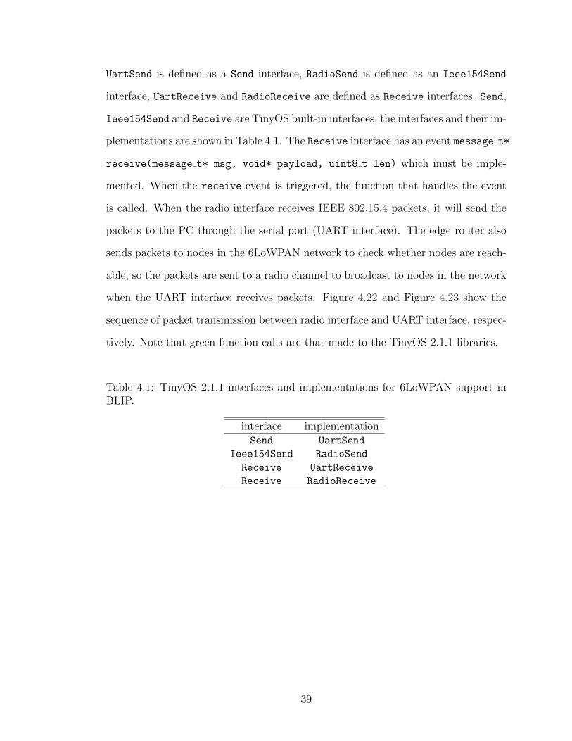
UartSend is defined as a Send interface, RadioSend is defined as an Ieee154Send
interface, UartReceive and RadioReceive are defined as Receive interfaces. Send,
Ieee154Send and Receive are TinyOS built-in interfaces, the interfaces and their im-
plementations are shown in Table 4.1. The Receive interface has an event message t*
receive(message t* msg, void* payload, uint8 t len) which must be imple-
mented. When the receive event is triggered, the function that handles the event
is called. When the radio interface receives IEEE 802.15.4 packets, it will send the
packets to the PC through the serial port (UART interface). The edge router also
sends packets to nodes in the 6LoWPAN network to check whether nodes are reach-
able, so the packets are sent to a radio channel to broadcast to nodes in the network
when the UART interface receives packets. Figure 4.22 and Figure 4.23 show the
sequence of packet transmission between radio interface and UART interface, respec-
tively. Note that green function calls are that made to the TinyOS 2.1.1 libraries.
Table 4.1: TinyOS 2.1.1 interfaces and implementations for 6LoWPAN support inBLIP.
interface implementationSend UartSend
Ieee154Send RadioSend
Receive UartReceive
Receive RadioReceive
39

Figure 4.22: Transmission of packets from radio to uart.
Figure 4.23: Transmission of packets from uart to radio.
4.4 Moving Node Software Implementation
4.4.1 Define Sensors
First, we need to define a data structure to store sensor readings. We add a new
data structure in TOSROOT/tos/lib/net/blip/Statistics.h, as follows:
40

1 typedef nx_struct
2 nx_uint16_t tsr; // visible to IR light sensor
reading
3 nx_uint16_t par; // visible light sensor reading
4 nx_uint16_t exttemp; // temperature sensor reading
5 nx_uint16_t hum; // humidity sensor reading
6 nx_uint16_t volt; // voltage sensor reading
7 nx_uint16_t sender; // ID of the sender
8 sensor_readings_t;
We also need to add reading interfaces in the UDPEchoP.nc file, ie.
1 interface Read <uint16_t > as ReadTSR;
2 interface Read <uint16_t > as ReadPAR;
3 interface Read <uint16_t > as ReadExtTemp;
4 interface Read <uint16_t > as ReadHum;
5 interface Read <uint16_t > as ReadVolt;
Five types of TelosB built-in sensors are used in this application. Table 4.2 shows
the detail information of the sensors.
Table 4.2: TelosB built-in sensors used in moving node application.
Sensor type Component in TinyOS Manufacturer UnitsVisible to IR Light Sensor HamamatsuS10871TsrC Hamamatsu Lux
Visible Light Sensor HamamatsuS1087ParC Hamamatsu LuxTemperature Sensor SensirionSht11C Sensirion %
Humidity Sensor SensirionSht11C Sensirion CVoltage Sensor Msp430InternalVoltageC Texas Instruments Volts
In order to use the interfaces, we need to add sensor components in the UDPEchoC.nc
file, ie.
1 components new HamamatsuS10871TsrC () as Sensor1;
2 components new HamamatsuS1087ParC () as Sensor2;
3 components new SensirionSht11C () as Sensor3;
4 components new DemoSensor () as Sensor4;
These components are part of the TinyOS source code.
Then we need to wire the interfaces to components, as follows:
1 UDPEchoP.ReadTSR -> Sensor1.Read;
2 UDPEchoP.ReadPAR -> Sensor2.Read;
3 UDPEchoP.ReadExtTemp -> Sensor3.Temperature;
4 UDPEchoP.ReadHum -> Sensor3.Humidity;
5 UDPEchoP.ReadVolt -> Sensor4.Read;
41

For each Read interface, it is required to implement a function to handle the readDone()
event. When a reading operation of one sensor is done, it should signal the next read-
ing. For example, the readDone() event for the visible to IR light sensor is:
1 event void ReadTSR.readDone(error_t result , uint16_t
data)
2 if (result == SUCCESS)
3 stats.udp.tsr = data;
4 call ReadPAR.read();
5
6
stats is a udp report data structure as follows:
1 nx_struct udp_report
2 nx_uint16_6 seqno;
3 nx_uint16_t sender;
4 ip_statistics_t ip;
5 sensor_readings_t udp;
6 icmp_statistics_t icmp;
7 route_statistics_t route;
8 ;
9
10 nx_struct udp_report stats;
The udp report data structure was originally defined in BLIP, and we added the
sensor readings t struct.
4.4.2 Sensor Readings Calculation
4.4.2.1 Light Sensors
TelosB has two built-in light sensors: Hamamatsu S1087 is a visible light sensor,
Hamamatsu S1087-01 is a visible to IR light sensor. The component of Hamamatsu
S1087 is HamamatsuS1087ParC.nc, the component of Hamamatsu S1087-01 is
HamamatsuS10871TsrC.nc. The current of the sensor (I) can be converted to lux
using the following formulas:
S1087 : lux = 0.769× 10⁵ × I × 1000 (4.1)
42

S1087− 01 : lux = 0.625× 10⁶ × I × 1000 (4.2)
Lux is the SI (International System of Units) unit of illuminance and luminous
emittance, measuring luminous flux per unit area [11]. The resistance at the output
is 100 kΩ, then the output current can be calculated by the following equation where
ADoutput is the sensor reading, Vref = 1.5 V:
I =Vsensor
100000 Ω;Vsensor = ADoutput ×
Vref
212(4.3)
4.4.2.2 Humidity and Temperature Sensor
Humidity and Temperature are measured using the same sensor Sensirion SHT11 on
TelosB, the component is SensirionSht11C.nc. The following formulas can convert
the sensor readings to humidity and temperature:
humidity = −0.0000028× data× data + 0.0405× data− 4 (4.4)
temperature = −40 + 0.01× data (4.5)
4.4.2.3 Voltage Sensor
The voltage sensor is the Msp430 internal voltage sensor, the component is
Msp430InternalVoltageC.nc. The value of the sensor readings can be converted to
voltage using the following formula:
voltage =data
4096× 3 (4.6)
43

Fig
ure
4.12
:Seq
uen
cedia
gram
ofse
ttin
gup
TC
Pso
cket
and
tunnel
inte
rfac
ein
theip-driver
pro
gram
.
44

Fig
ure
4.13
:Seq
uen
cedia
gram
ofop
enin
ga
seri
alp
ort
and
init
ializi
ng
routi
ng
inip
-dri
ver.
45

Figure 4.14: Sequence diagram of tunneling process of receiving data.
Figure 4.15: Sequence diagram of tun input().
46

Fig
ure
4.16
:Seq
uen
cedia
gram
ofserialinput().
47

Figure 4.17: Definition of data type serial source t.
Figure 4.18: Definition of data type packed lowmsg t.
Figure 4.20: Definition of data type reconstruct t.
48

Chapter 5
Experimental Design and Results
5.1 Mobile Wireless Sensor Architecture
We evaluated the moving node dynamically using a mobile sensor network testbed.
The testbed uses a model train (see Figure 5.1) to carry our moving nodes (see
Figure 5.2).
Figure 5.1: Model train running on the wireless sensor network testbed in ITB214.
49

Figure 5.2: A Telosb node is carried on the model train.
The testbed model railroad track is hanging from light fixtures in the wireless com-
munications lab ITB214 (see Figure 5.3).
50

Figure 5.3: General view of train track in ITB214.
The parameters of testbed are shown in Figure 5.4.
51

Figure 5.4: Model railroad track in ITB214.
A, B, C, D, E, F in Figure 5.4 show the approximate positions of the stationary
nodes; moving nodes are on one or two model trains. The railroad train track has
two short sides, two long sides and four corners. The corner is shown in Figure 5.5.
52

Figure 5.5: Model railroad track corner.
5.2 Experimental Testing Software Architecture
5.2.1 Packet Specification
In our testing, the moving node sends UDP packets to the edge router over IPv6.
The whole UDP packet structure is shown in Figure 5.6. In our testing, the whole
UDP packet size is 189 bytes, and the payload of UDP packet is 141 bytes as shown
in Figure 5.6. Figure 5.7 shows the payload of one UDP packet used in our testing.
The payload begins from the 49th byte of the UDP packet shown in Figure 5.6, each
field of the payload is illustrated in Table 5.1.
53

Figure 5.6: Packet structure of UDP over IPv6.
Figure 5.7: 141 bytes Payload structure.
54

Table 5.1: UDP payload structure.
Field size (in bytes) Meaning
seqno 2 Packet sequence number
sender 2 The TOS NODE ID of the sender node
ip stat 9 IP statistics
sensor reading 12 Sensor reading values
ICMP stat 9 ICMP statistics
route stat 7 Route statistics
data 100 An array of zeros
The following is the details of the payload fields.
1. seqno: Packet sequence number is a 16-bit integer, seqno increments by one
for each out going packet from the sender node.
2. sender: The TOS NODE ID of the sender node, TOS NODE ID is specified
when downloading the program to sensor node. In our testing, the
TOS NODE ID of the moving nodes are 1 and 8.
3. ip stat: ip stat is of type ip statistics t, it is TinyOS built-in data structure.
4. sensor reading: sensor reading is of type sensor readings t, Figure 5.8 shows
the specification of sensor reading.
5. ICMP stat: ICMP stat is of type icmp statistics t, it is TinyOS built-in
data structure.
6. route stat: route stat is of type route statistics t, it is TinyOS built-in
data structure.
55

7. data: data is an array of zeros, the size of the array is 100 bytes. We need this
array to force each UDP packet to exceed 127 bytes, so that one UDP packet
can be fragmented into several 6LoWPAN fragments.
The details of the data structures used in UDP packets can be found in Appendix A.1.
Figure 5.8: Packet specification of field sensor reading.
5.2.2 Testing software architecture
Figure 5.9 shows the architecture of the software testing system.
Figure 5.9: Monitor.java monitors the topology changes of the network, andUDPMonitor.py stores all the received UDP packets and calculates packet loss.
5.2.2.1 Detecting Packet Route Topology Change
Our Java testing program is called Monitor.java. As shown in Figure 5.11,
Monitor.java builds a TCP socket connection to the server which is running ip-driver
56

on port 6106. As discussed in Section 4.2, ip-driver is a C program that opens a
TCP socket and keeps listening on port 6106. Monitor.java has one input stream
called in which is an object of type BufferedReader and one output stream called
out which is an object of type PrintWriter. Object in is used to receive messages
from ip-driver and out is used to send messages to ip-driver. When a client
is connected to ip-driver, the client receives a welcome message. Monitor.java
stores the welcome message in a buffer. In our experiment, we monitor the topology
changes when nodes are moving, so Monitor.java keeps sending the routes com-
mand to ip-driver using the PrintWriter. An example output from the routes
command is shown in Figure 5.10. Algorithm 5.1 shows the main topology change
detection logic used in the Monitor.java program.
Figure 5.10: A sample response to the routes command.
Route information of each node returned by ip-driver is stored in a Java HashMap
object. The sending of a routes command to ip-driver and the receiving of route
information from ip-driver are synchronized, which means that Monitor.java will
not send the next routes command to ip-driver until it receives all the data from
the socket input stream. Monitor.java makes sure it receives all the data from the
socket input stream by checking whether the return value of in’s readLine method
is null (see line 5 of Algorithm 5.1).
57

When Monitor.java receives a node’s route information, the program checks whether
the node exists in the HashMap (see line 21 of Algorithm 5.1).
58

Algorithm 5.1: Algorithm for detecting wireless sensor network topologychanges.
Input: continuous lines of route strings output by ip-driver “routes”command
Output: Detecting topology changes and storing changed routes inroute info.log
1 Map path ← HashMap whose keys and values are of type String;2 PrintWriter out ; /* to ip-driver */
3 BufferedReader in ; /* from ip-driver */
4 String msg;5 out.println(“routes”);6 while (msg ← in.readLine()) 6= NULL do7 if msg starts with “blip” then8 arrowIndex ← msg.indexOf(“>”);9 msg ← msg.substring(arrowIndex +1);
10 end11 if msg equals “0x64” then12 out.println(“routes”);13 else14 String[] splitMsg ← msg.split(“:”);15 String node ; /* left part */
16 String route ; /* right part */
17 node ← splitMsg [0];18 if splitMsg.length > 1 then19 route ← splitMsg [1];20 end21 if path.containsKey(node) and route 6= NULL then22 String oldPath ← path.get(node).split(“&”)[0];23 if oldPath 6= route then24 String changeTime ← current time ; /* use Java Date
object */
25 String routeAndTime ← route + “&” + changeTime;26 path.put(node, routeAndTime);
27 end
28 else29 if route 6= NULL then30 String changeTime ← current time;31 String routeAndTime ← route + “&” + changeTime;32 path.put(node, routeAndTime);
33 end
34 end
35 end
36 end
59

If the node does not exist in the HashMap, Monitor.java adds the new node with its
route information and time stamp concatenated using the “&” symbol to separate
the route and time stamp (see lines 30 to 34 of Algorithm 5.1). If the node exists
in the HashMap, Monitor.java checks whether the stored route of the node is the
same as the received route. If the routes are different, Monitor.java updates the
node’s route to be the new received route (see lines 23 to 27 of Algorithm 5.1),
and saves the node’s new route to a log file route info.log. If the routes are the
same, Monitor.java ignores the update. Figure 5.11 shows the message passing
process between Monitor and ip-driver. Figure 5.12 shows a portion of a sample
route info.log file.
Figure 5.11: Message passing between Monitor and ip-driver.
Figure 5.12: A portion of a sample route info.log file.
The new routes information is read line by line, so Monitor.java receives one line
at each interation. Lines 6 to 9 in Algorithm 5.1 get rid of the BLIP console message
(e.g. blip:ib214m06.cs.unb.ca>). The address of the edge router is set to 0x64
in a config file serial tun.conf, and it does not have a route, so lines 10 and 11
60

ignore a 0x64 only route, and send the next routes command. If the source of the
new route is not 0x64, Algorithm 5.1 splits the new message received into two parts:
source node and route (lines 13 to 19). For example, message
0x7: [1.0]0x6 [1.0]0x4 [1.0]0x64
can be split into 0x7 and [1.0]0x6 [1.0]0x4 [1.0]0x64, where 0x7 is the source
node and [1.0]0x6 [1.0]0x4 [1.0]0x64 is the route. A Java hash map is used
to store the latest nodes’ routes. As shown in lines from 29 to 35, if node 0x7 does
not exist in the hash map, Algorithm 5.1 adds node 0x7 and its route [1.0]0x6
[1.0]0x4 [1.0]0x64 with the current time into the hash map, where node is the
key, and the route with current time routeAndTime is the value (route and change
time are separated by the “&” character). If node 0x7 already exists in the hash
map, Algorithm 5.1 compares the stored route of node 0x7 and the most recent
route. If they are not equal, Algorithm 5.1 stores the most recent route of node 0x7
to the hash map as shown in lines 21 to 28. All changed routes are recorded in the
route info.log file.
5.2.2.2 Measuring Packet Loss
A Python program called UDPMonitor.py calculates packet loss during testing. The
moving node sends UDP packets through port 7001 to the edge router port 7000, so
UDPMonitor.py opens a socket on port 7000 to receive UDP packets from the edge
router using the following Python statements:
1 s = socket.socket(socket.AF_INET6 , socket.SOCK_DGRAM)
2 s.bind((’fec0 ::64’, 7000))
The packet loss is calculated using equation (5.1),
PL = 100(T −R)/T (5.1)
where PL is packet loss in percent, T is the number of UDP packets transmitted
61

during a specific time period (e.g. five hours), and R is the number of UDP packets
received during the same time period. The UDP packets are read by line 21 in the
UDPMonitor.py program given in Appendix C.2 as follows:
21 data , addr = s.recvfrom (65535)
where data is the byte stream of received UDP packets, addr is the source address
of UDP packets, and 65535 is the maximum length of one received packet. If the
length of data is greater than 0 (indicating a successfully received UDP packet), R
increments by one, as shown in Algorithm 5.2. The first two bytes of data indicate
the packet sequence number, which is a 16-bit integer. We assign the sequence num-
ber to T first. The first UDP packet’s sequence number is one, and the sequence
number increments by one for each UDP packet sent from the moving node. When
UDPMonitor.py starts running, we assign the sequence number of the first received
UDP packet minus one to offset O. T is translated by offset O to T −O to account
for the fact that the first received packet is likely not sequence number 1.
62

Algorithm 5.2: Algorithm for calculating packet loss in programUDPMonitor.py.
Input: continuous UDP packets on port 7000Output: UDP packet loss in percent, and the received packets stored in the
file UDP.log
1 T ← 0;2 R ← 0;3 while time elapsed ≤ 5 hours do4 data← recvfrom “fec0::64” port 7000;5 print data to UDP.log;6 if length of data > 0 then7 R← R + 1;8 high ← first byte;9 low ← second byte;
10 T← high× 256 + low ; /* sequence number (seqno) of
transmitted packet */
11 if R == 1 then /* account for the first received packet */
12 O← T− 1;13 end14 T← T− O;15 PL← 100× (T− R)/T;16 print T, R, PL to UDP.log;
17 end
18 end
The payload of one data packet is 141 bytes long, as specified in Section 5.2.1 and Ta-
ble 5.1. Figure 5.13 illustrates the packet loss measurement process. The ip-driver
program sends out the complete UDP packet to the destination in the wireless area
network (e.g. fec0::64 on port 7000 in our wireless sensor network) after reassem-
bly. As UDP packets are sent at a rate of one packet per 10 seconds, this means we
obtain approximately 360 records per hour in the UDP.log file.
63
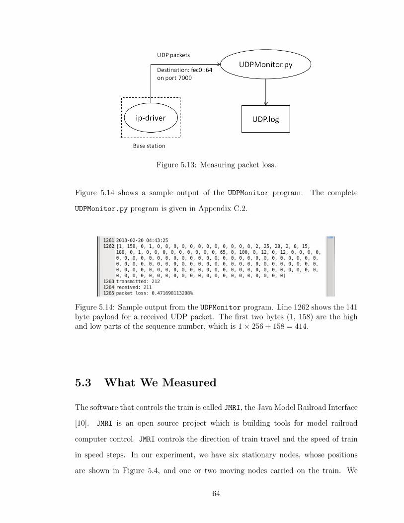
Figure 5.13: Measuring packet loss.
Figure 5.14 shows a sample output of the UDPMonitor program. The complete
UDPMonitor.py program is given in Appendix C.2.
Figure 5.14: Sample output from the UDPMonitor program. Line 1262 shows the 141byte payload for a received UDP packet. The first two bytes (1, 158) are the highand low parts of the sequence number, which is 1× 256 + 158 = 414.
5.3 What We Measured
The software that controls the train is called JMRI, the Java Model Railroad Interface
[10]. JMRI is an open source project which is building tools for model railroad
computer control. JMRI controls the direction of train travel and the speed of train
in speed steps. In our experiment, we have six stationary nodes, whose positions
are shown in Figure 5.4, and one or two moving nodes carried on the train. We
64

test topology changes and packet loss of the wireless sensor network under different
train velocities and different routing table update periods. The default routing table
update period is 60 seconds. In our experiments, we modified the routing table
update period to 6 seconds, and 0.6 seconds. This update was made by changing
the period of the SortTimer in the IPRouting.nc file. The speeds we chose in the
experiment are 40, 60, 80, 100, and 120 (in speed steps). Speed step velocities map
nonlinearly to actual speed, so we measured the actual velocities by recording the
time required for the train to travel three times around the track. We used both the
inner track and outer track in our testing, which have length of 23.92m and 24.36m,
respectively. Engine 6404 is on the inner track and engine 1478 is on the outer track.
The actual velocities corresponding to each speed step are shown in Table 5.2 and
Table 5.3.
Table 5.2: Speed step velocities map for train engine 6404.
Speed Steps 40 60 80 100 120
Time Consumed 15:45 8:09 5:22 3:58 3:11
Velocity (m/s) 0.0759 0.1466 0.2229 0.3015 0.3757
Table 5.3: Speed step velocities map for train engine 1478.
Speed Steps 40 60 80 100 120
Time Consumed 20:51 10:23 6:48 4:56 4:04
Velocity (m/s) 0.0584 0.1173 0.1791 0.2469 0.2995
The sensor nodes used in the experiment are TelosB nodes that consist of an 8 MHz
TI MSP430 microcontroller with 10 kB RAM, and an IEEE 802.15.4 2.4 GHz radio
cc2420, our experiment operating system for sensor nodes is Tinyos 2.1.1. Each test
uses six stationary nodes and one moving node, and we recorded all the received
UDP packets and the topology changes of the wireless sensor network over a five
65

hour period. Packet loss was measured as described in Section 5.2.2.2.
5.3.1 Testing Results
5.3.1.1 One Moving Node Testing
The moving node address is fec0::1 for one moving node testing. Table 5.4 shows
the number of topology changes (NTC) and packet loss (PL) with different train
speeds using engine 6404, and different routing table update periods (RTUP).
Table 5.4: Number of topology changes (NTC) and packet loss under different routingtable update periods, and different train velocities in one moving node testing.
Test RTUP Speed Steps NTC R/T PL1 60 40 99 1845 / 1845 0.000%2 60 60 148 1845 / 1845 0.000%3 60 80 97 1844 / 1845 0.054%4 60 100 310 1845 / 1845 0.000%5 60 120 334 1844 / 1845 0.054%6 6 40 315 1843 / 1845 0.108%7 6 60 403 1845 / 1845 0.000%8 6 80 379 1843 / 1846 0.163%9 6 100 583 1843 / 1845 0.108%10 6 120 682 1843 / 1845 0.108%11 0.6 40 398 1840 / 1845 0.271%12 0.6 60 335 1836 / 1845 0.489%13 0.6 80 428 1839 / 1845 0.325%14 0.6 100 472 1832 / 1946 0.758%15 0.6 120 842 1819 / 1845 1.409%
Figure 5.15 shows packet loss vs. train velocity with different routing table update
periods. We can see from Figure 5.15 that packet loss increases when the routing
table update period becomes shorter. Routing table update periods of 60 seconds
and 6 seconds have the same packet loss for high and low train velocity, while a
routing table update period of 0.6 seconds has increasing packet loss with increasing
train velocity. The network with the BLIP default routing table update period of 60
66

seconds is the most reliable one.
Figure 5.15: Packet loss vs. train velocity for one moving node testing.
To make sure the experimental readings we obtained are consistent, we repeated the
one moving node testing experiment for a RTUP of 0.6 seconds. The result is shown
as the April 15 0.6 seconds RTUP data line in Figure 5.15. As we can see, the packet
loss still increases when train velocity goes faster, so our observation that packet loss
increases significantly with a 0.6 seconds RTUP is repeatable.
Figure 5.16 plots the number of topology changes vs. train velocity under differ-
ent routing table update periods. We can see from Figure 5.16 that the number
of topology changes increases when the routing table update period decreases, and
the number of topology changes is more likely to increase when velocity becomes
faster. The fewest topology changes occur when the routing table update period is
the default value of 60 seconds.
67

Figure 5.16: Number of topology changes vs. train velocity for one moving nodetesting.
5.3.1.2 Two Moving Nodes Testing
The moving nodes addresses are fec0::1 (behind engine 6404) and fec0::8 (be-
hind engine 1478) in the two moving nodes testing. Table 5.5 shows the number of
topology changes (NTC) and packet loss (PL) with different train speed steps (SS)
and different routing table update periods (RTUP) in two moving nodes testing.
68

Table 5.5: Number of topology changes (NTC) and packet loss under different routingtable update periods, and different train velocities in two moving node testing.
Test RTUP SS NTC R/T (fec0::1) PL(fec0::1) R/T (fec0::8) PL(fec0::8)1 60 40 175 1796/1801 0.278% 1791/1801 0.555%2 60 60 356 1792/1800 0.444% 1798/1801 0.167%3 60 80 252 1801/1801 0.000% 1798/1801 0.167%4 60 100 385 1797/1800 0.167% 1795/1801 0.333%5 60 120 340 1801/1801 0.000% 1801/1801 0.000%6 6 40 1124 1794/1801 0.389% 1795/1801 0.333%7 6 60 1033 1796/1801 0.278% 1800/1801 0.056%8 6 80 810 1793/1801 0.444% 1793/1801 0.444%9 6 100 570 1801/1801 0.000% 1799/1801 0.111%10 6 120 771 1795/1801 0.333% 1798/1801 0.167%11 0.6 40 781 1798/1801 0.167% 1798/1801 0.167%12 0.6 60 672 1795/1801 0.333% 1798/1801 0.167%13 0.6 80 909 1794/1801 0.389% 1780/1801 1.166%14 0.6 100 691 1784/1801 0.944% 1788/1801 0.722%15 0.6 120 262 1796/1801 0.278% 1792/1801 0.500%
Figure 5.17 shows packet loss vs. train velocity with different routing table update
periods. Figure 5.18 shows the total packet loss vs. train velocity with different
routing table update periods. Figure 5.19 shows the number of topology changes vs.
train velocity under different routing table update periods.
69

Figure 5.17: Packet loss vs. train velocity for two moving nodes testing.
Figure 5.18: Total packet loss vs. train velocity for two moving nodes testing.
From Figure 5.17 and Figure 5.18, we can see that packet loss is higher at 0.6 seconds
70

routing table update period, but unlike single node testing, the packet loss decreases
as velocity goes higher at 0.6 seconds RTUP and velocity of 100 (in speed steps,
the two engines used in the two nodes testing have different speed steps to actual
velocity mapping) for node fec0::8, and velocity of 100 (in speed steps) for node
fec0::1. Both one node testing and two nodes testing show that the BLIP default
RTUP of 60 seconds has the smallest packet loss.
Figure 5.19: Number of topology changes vs. train velocity for two moving nodetesting.
We can see from Figure 5.18 that when the train velocity is greater than 60 (in speed
steps), routing table update period of 0.6 seconds has higher packet loss than routing
table update period of 60 seconds and 6 seconds.
71

Chapter 6
Summary and Conclusions
6.1 Summary
A detailed explanation of sending and receiving UDP messages using the Berkeley
Low Power IP (BLIP) stack is provided in this thesis. A 6LoWPAN wireless sensor
network with both one and two moving nodes and six stationary nodes has been
built and tested under different BLIP routing table update periods and different
train velocities. TelosB sensor nodes were used in all the experimental tests. The
experimental results show that the 6LoWPAN protocol can accommodate objects
moving at a rate up to 0.38 m/s. The maximum packet loss in our testing was 1.41%
over a period of five hours. Our tests with routing table update periods of 60 s, 6
s, and 0.6 s showed that BLIP operates successfully in all three update periods. We
observed that a RTUP of 0.6 s had an approximately 13 times higher packet loss
compared to a 6 s RTUP, and 26 times higher packet loss compared to a 60 s RTUP
where the moving node has a 0.376 m/s velocity.
A Java-based web application has been implemented to monitor mobile nodes mov-
ing in a wireless sensor network and communicating with a 6LoWPAN protocol.
72

WebSocket and TCP sockets are used to transmit route topology messages to client
browsers, and UDP packets are used to transmit sensor readings from sensor nodes.
6.2 Conclusions
Having 0.6 second routing table update period (RTUP) resulted in a higher packet
loss than with a 6 second or 60 second RTUP. In one moving node testing, routing
table update rate of 0.6 s has significantly higher packet loss (up to 1.4% compared
to 0.16%). In two moving nodes testing, the maximum packet loss of 0.6 second
RTUP is approximately 1.2%, which is higher than packet loss of 6 second RTUP
and 60 second RTUP (most of packet losses of 6 second RTUP and 60 second RTUP
are between 0.2% and 0.4%).
6.3 Future Work
Future work on evaluating mobile nodes moving inside a wireless sensor network
might include the following topics:
1. Testing of different sensor platforms instead of just TelosB (e.g. MicaZ, IRIS,
TinyNode) could illustrate the robustness of 6LoWPAN with different hard-
ware.
2. Our tests were all done at the lowest power level 3, would the packet loss
decrease if higher power levels were used?
3. Our 24 m long mobile wireless network testbed track is too small for measuring.
Extending the track to permit e.g. 250 m or more of travel distance would
provide a more complete evaluation of the 6LoWPAN protocol under longer
wireless distances.
73

4. The user interface of the WSNWeb application could be improved if that po-
sition information was available to display the accurate position of the train
running in the wireless communication lab ITB214.
74

References
[1] Apache Tomcat, http://tomcat.apache.org/, Accessed March, 2013.
[2] Atmel RZUSBstick, http://www.atmel.com/tools/rzusbstick.aspx, Ac-cessed January, 2013.
[3] BerkeleyWEBS Wireless embedded systems, http://smote.cs.berkeley.edu:8000/tracenv/wiki/blip, Accessed July, 2011.
[4] Embedding Jetty on eclipse, http://wiki.eclipse.org/Jetty/Tutorial/
Embedding\_Jetty, Accessed March, 2013.
[5] Graphviz - Graph Visualization Software, http://www.graphviz.org/, Ac-cessed April 5, 2013.
[6] HTML5 Canvas at w3schools.com, http://www.w3schools.com/html/html5\_canvas.asp, Accessed March, 2013.
[7] IEEE 802.15 WPAN Task Group 4 (TG4), http://www.ieee802.org/15/pub/TG4.html, Accessed August, 2011.
[8] JavaScript Graphics Lirary (JSGL.org), http://www.jsgl.org/doku.php?id=home, Accessed March 25, 2013.
[9] Jetty WebSocket, http://wiki.eclipse.org/Jetty/Feature/WebSockets, AccessedFebruary, 2013.
[10] Jmri, http://jmri.sourceforge.net/, Accessed February, 2013.
[11] LUX on Wikipedia, http://en.wikipedia.org/wiki/Lux, Accessed Decem-ber, 2011.
[12] Tomcat Architecture - Startup, http://tomcat.apache.org/tomcat-5.5-doc/architecture/startup.html, Accessed March, 2013.
[13] G. Barrenetxea, F. Ingelrest, G. Schaefer, M. Vetterli, O. Couach, and M. Par-lange, Sensorscope: Out-of-the-box environmental monitoring, Information Pro-cessing in Sensor Networks, 2008. IPSN ’08. International Conference on, April2008, pp. 332 –343.
75

[14] Ed. J. Hui and P. Thubert, Compression format for ipv6 datagrams in low powerand lossy networks, Tech. report, February 2011, IETF draft-ietf-6lowpan-hc-15,update 4944 (if aapproved).
[15] Philo Juang, Hidekazu Oki, Yong Wang, Margaret Martonosi, Li-Shiuan Peh,and Daniel Rubenstein, Energy-efficient computing for wildlife tracking: designtradeoffs and early experiences with zebranet, Proceedings of the 10th Interna-tional Conference on Architectural Support for Programming Languages andOperating Systems, 2002, pp. 96–107.
[16] G. Montenegro, N. Kushalnagar, J. Hui, and D. Culler, Transmission of IPv6Packets over IEEE 802.15.4 Networks, Ietf request for comments rfc4944,September 2007.
[17] C. Schumacher N. Kushalnagar, G. Montenegro, IPv6 over Low-Power Wire-less Personal Area Networks (6LoWPANs): Overview, Assumptions, ProblemStatement, and Goals, Tech. report, 2007.
[18] Krishna Sampigethaya, Radha Poovendran, Mingyan Li, Linda Bushnell, andRichard Robinson, Security of wireless sensor network enabled health monitoringfor future airplanes, 26th International Congress of The Aeronautical Sciencesat Alaska, USA, September 2008, ICAS Paper Number: ICAS 2008-9.1.3.
[19] Lucie Smith and Ian Lipner, Free Pool of IPv4 Address Space Depleted, http://www.nro.net/news/ipv4-free-pool-depleted, Accessed July, 2011.
[20] Lohith Y.S., 6LowPAN: Wireless Internet Of Things, Presentation at Depart-ment of ECE, Indian Institue of Science, Bangalore, November 2010.
[21] Gang Zhao, Wireless sensor networks for industrial process monitoring and con-trol: A survey, Network Protocols and Algorithms 3 (2011), no. 1, 46–63.
76

Appendix A
Moving Node Software
A.1 Data Structures Used in UDP Packets in Test-
ing
UDPReport.h composes the definition for the UDP payload structure.
Listing A.1: UDPReport.h1 #ifndef UDPREPORT H2 #define UDPREPORT H34 #include <S t a t i s t i c s . h>5 #include <AM. h>67 nx s t ru c t udp report 8 nx u in t16 t seqno ;9 nx u in t16 t sender ;10 i p s t a t i s t i c s t ip ;11 s e n s o r r e a d i n g s t udp ;12 i cm p s t a t i s t i c s t icmp ;13 r o u t e s t a t i s t i c s t route ;14 nx u in t16 t data [ 5 0 ] ;15 ;1617 #endif
Statistics.h contains the definitions for each field of UDP payload.
Listing A.2: Statistics.h1 /∗ S t a t i s t i c s from the core 6 lowpan/IPv6 fragmentat ion and forwarding engine ∗/2 typedef nx s t ru c t 3 nx u in t16 t sent ; // t o t a l IP datagrams sent4 nx u in t16 t forwarded ; // t o t a l IP datagrams forwarded5 nx u in t8 t rx drop ; // L2 f r a g s dropped due to 6 lowpan f a i l u r e6 nx u in t8 t tx drop ; // L2 f r a g s dropped due to l i n k f a i l u r e s7 nx u in t8 t fw drop ; // L2 f r a g s dropped when forwarding due to queue over f l ow8 nx u in t8 t r x t o t a l ; // L2 f r a g s r ece i v ed9 nx u in t8 t e n c f a i l ; // f r a g s dropped due to send queue
77

10 i p s t a t i s t i c s t ;1112 typedef nx s t ru c t 13 nx u in t8 t hop l im i t ;14 nx u in t16 t parent ;15 nx u in t16 t parent met r i c ;16 nx u in t16 t parent e tx ;17 r o u t e s t a t i s t i c s t ;1819 typedef nx s t ru c t 20 nx u in t8 t s o l r x ;21 nx u in t8 t s o l t x ;22 nx u in t8 t adv rx ;23 nx u in t8 t adv tx ;24 nx u in t8 t echo rx ;25 nx u in t8 t echo tx ;26 nx u in t8 t unk rx ;27 nx u in t16 t rx ;28 i cm p s t a t i s t i c s t ;2930 /∗ sensor read ings we de f ined ∗/31 typedef nx s t ru c t 32 nx u in t16 t t s r ;33 nx u in t16 t par ;34 nx u in t16 t exttemp ;35 nx u in t16 t hum;36 nx u in t16 t vo l t ;37 nx u in t16 t sender ;38 s e n s o r r e a d i n g s t ;
A.2 Main Program for Moving Node
UDPMovingC.nc contains the configuration for the moving node application.
Listing A.3: UDPMovingC.nc1 #include <6lowpan . h>2 #ifdef DBGTRACKFLOWS3 #include ”TestDriver . h”4 #endif56 c on f i gu r a t i on UDPMovingC 78 implementation 9 components new HamamatsuS10871TsrC ( ) as Sensor1 ;10 components new HamamatsuS1087ParC ( ) as Sensor2 ;11 components new Sens ir ionSht11C ( ) as Sensor3 ;12 components new DemoSensorC ( ) as Sensor4 ;1314 UDPMovingP .ReadTSR −> Sensor1 . Read ;15 UDPMovingP .ReadPAR −> Sensor2 . Read ;16 UDPMovingP . ReadExtTemp −> Sensor3 . Temperature ;17 UDPMovingP .ReadHum −> Sensor3 . Humidity ;18 UDPMovingP . ReadVolt −> Sensor4 . Read ;1920 components MainC , LedsC ;21 components UDPMovingP ;2223 UDPMovingP . Boot −> MainC ;24 UDPMovingP . Leds −> LedsC ;25
78

26 components new TimerMill iC ( ) ;27 components IPDispatchC ;2829 UDPMovingP . RadioControl −> IPDispatchC ;30 components new UdpSocketC ( ) as Status ;3132 UDPMovingP . Status −> Status ;3334 UDPMovingP . StatusTimer −> TimerMill iC ;3536 components UdpC;37 UDPMovingP . IPStats −> IPDispatchC . IPStats ;38 UDPMovingP . UDPStats −> UdpC;39 UDPMovingP . RouteStats −> IPDispatchC . RouteStats ;40 UDPMovingP . ICMPStats −> IPDispatchC . ICMPStats ;4142 #ifdef SIM43 components BaseStationC ;44 #endif45 #ifdef DBGTRACKFLOWS46 components TestDriverP , Ser ia lAct iveMessageC as S e r i a l ;47 components ICMPResponderC , IPRoutingP ;48 TestDriverP . Boot −> MainC ;49 TestDriverP . S e r i a lCon t r o l −> S e r i a l ;50 TestDriverP . ICMPPing −> ICMPResponderC . ICMPPing [ unique ( ”PING” ) ] ;51 TestDriverP . CmdReceive −> S e r i a l . Rece ive [AM TESTDRIVERMSG] ;52 TestDriverP . IPRouting −> IPRoutingP ;53 TestDriverP . DoneSend −> S e r i a l .AMSend [AM TESTDRIVERMSG] ;54 TestDriverP . AckSend −> S e r i a l .AMSend [AM TESTDRIVER ACK] ;55 TestDriverP . RadioControl −> IPDispatchC ;56 #endif57 #ifdef DBGFLOWSREPORT58 components TrackFlowsC ;59 #endif60
UDPMovingP.nc composes the module UDPMovingP for the moving node application.
Listing A.4: UDPMovingP.nc1 #include <IPDispatch . h>2 #include <l ib6 lowpan . h>3 #include <ip . h>4 #include <l ib6 lowpan . h>5 #include <ip . h>6 #include ”UDPReport . h”7 #include ”PrintfUART . h”89 #define REPORT PERIOD 75L10 #define REPORT DEST ” f e c0 : : 6 4 ”1112 module UDPMovingP 13 uses 14 i n t e r f a c e Boot ;15 i n t e r f a c e Sp l i tCon t r o l as RadioControl ;16 i n t e r f a c e UDP as Status ;1718 i n t e r f a c e Leds ;1920 i n t e r f a c e Timer<TMil l i> as StatusTimer ;2122 i n t e r f a c e S t a t i s t i c s < i p s t a t i s t i c s t > as IPStats ;23 // i n t e r f a c e S t a t i s t i c s <u d p s t a t i s t i c s t > as UDPStats ;24 i n t e r f a c e S t a t i s t i c s <s e n s o r r e ad i n g s t> as UDPStats ;25 i n t e r f a c e S t a t i s t i c s <r o u t e s t a t i s t i c s t > as RouteStats ;26 i n t e r f a c e S t a t i s t i c s <i cmp s t a t i s t i c s t > as ICMPStats ;2728 i n t e r f a c e Read<u int16 t> as ReadTSR ;29 i n t e r f a c e Read<u int16 t> as ReadPAR;
79

30 i n t e r f a c e Read<u int16 t> as ReadExtTemp ;31 i n t e r f a c e Read<u int16 t> as ReadHum;32 i n t e r f a c e Read<u int16 t> as ReadVolt ;3334 3536 implementation 3738 bool t imerStar ted ;39 nx s t ru c t udp report s t a t s ;40 struct sockaddr in6 r ou t e d e s t ;414243 event void Boot . booted ( ) 44 c a l l RadioControl . s t a r t ( ) ;45 t imerStar ted = FALSE;4647 c a l l IPStats . c l e a r ( ) ;48 c a l l RouteStats . c l e a r ( ) ;49 c a l l ICMPStats . c l e a r ( ) ;50 printfUART init ( ) ;5152 #ifdef REPORT DEST53 r ou t e d e s t . s i n 6 po r t = hton16 (7000) ;54 i n e t p ton6 (REPORT DEST, &rou t e d e s t . s in6 addr ) ;55 // c a l l StatusTimer . startOneShot ( c a l l Random. rand16 () % (1 nx u in t 16 t ∗1024 ∗
REPORT PERIOD) ) ;56 c a l l StatusTimer . s t a r tP e r i o d i c (10000) ;57 #endif5859 dbg ( ”Boot” , ”booted : %i \n” , TOS NODE ID) ;60 c a l l Status . bind (7001) ;61 6263 event void RadioControl . startDone ( e r r o r t e ) 6465 6667 event void RadioControl . stopDone ( e r r o r t e ) 6869 7071 event void Status . recvfrom ( struct sockaddr in6 ∗ from , void ∗data ,72 u in t 16 t len , struct ip metadata ∗meta ) 7374 7576 event void StatusTimer . f i r e d ( ) 7778 i f ( ! t imerStar ted ) 79 // c a l l StatusTimer . s t a r tPe r i o d i c (1024 ∗ REPORT PERIOD) ;8081 t imerStar ted = TRUE;82 83 c a l l Leds . l ed0Toggle ( ) ;84 s t a t s . seqno++;85 s t a t s . sender = TOS NODE ID ;8687 c a l l IPStats . get (& s t a t s . ip ) ;88 c a l l UDPStats . get (& s t a t s . udp ) ;89 s t a t s . udp . sender = TOS NODE ID ;90 c a l l ICMPStats . get (& s t a t s . icmp ) ;91 c a l l RouteStats . get (& s t a t s . route ) ;92 c a l l ReadTSR . read ( ) ;9394 c a l l Status . sendto(&route de s t , &s ta t s , s izeof ( s t a t s ) ) ;95 96
80

97 event void ReadTSR . readDone ( e r r o r t r e su l t , u i n t 16 t data ) 98 i f ( r e s u l t == SUCCESS) 99 s t a t s . udp . t s r = data ;
100 c a l l ReadPAR. read ( ) ;101 102 103104 event void ReadPAR. readDone ( e r r o r t r e su l t , u i n t 16 t data ) 105 i f ( r e s u l t == SUCCESS) 106 s t a t s . udp . par = data ;107 c a l l ReadExtTemp . read ( ) ;108 109 110111 event void ReadExtTemp . readDone ( e r r o r t r e su l t , u i n t 16 t data ) 112 i f ( r e s u l t == SUCCESS) 113 s t a t s . udp . exttemp = data ;114 c a l l ReadHum. read ( ) ;115 116 117118 event void ReadHum. readDone ( e r r o r t r e su l t , u i n t 16 t data ) 119 i f ( r e s u l t == SUCCESS) 120 s t a t s . udp .hum = data ;121 c a l l ReadVolt . read ( ) ;122 123 124125 event void ReadVolt . readDone ( e r r o r t r e su l t , u i n t 16 t data ) 126 i f ( r e s u l t == SUCCESS) 127 s t a t s . udp . vo l t = data ;128 129 130
81

Appendix B
Stationary Node Software
UDPMovingC.nc contains the configuration for the stationary node application.
Listing B.1: UDPStationaryC.nc1 #include <6lowpan . h>2 #ifdef DBGTRACKFLOWS3 #include ”TestDriver . h”4 #endif56 c on f i gu r a t i on UDPStationaryC 78 implementation 910 components MainC , LedsC ;11 components UDPStationaryP ;1213 UDPStationaryP . Boot −> MainC ;14 UDPStationaryP . Leds −> LedsC ;1516 components new TimerMill iC ( ) ;17 components IPDispatchC ;1819 UDPStationaryP . RadioControl −> IPDispatchC ;20 components new UdpSocketC ( ) as Status ;2122 UDPStationaryP . Status −> Status ;2324 UDPStationaryP . StatusTimer −> TimerMill iC ;2526 components UdpC;27 UDPStationaryP . IPStats −> IPDispatchC . IPStats ;28 UDPStationaryP . UDPStats −> UdpC;29 UDPStationaryP . RouteStats −> IPDispatchC . RouteStats ;30 UDPStationaryP . ICMPStats −> IPDispatchC . ICMPStats ;3132 components UDPShellC ;3334 #ifdef SIM35 components BaseStationC ;36 #endif37 #ifdef DBGTRACKFLOWS38 components TestDriverP , Ser ia lAct iveMessageC as S e r i a l ;39 components ICMPResponderC , IPRoutingP ;40 TestDriverP . Boot −> MainC ;
82

41 TestDriverP . S e r i a lCon t r o l −> S e r i a l ;42 TestDriverP . ICMPPing −> ICMPResponderC . ICMPPing [ unique ( ”PING” ) ] ;43 TestDriverP . CmdReceive −> S e r i a l . Rece ive [AM TESTDRIVERMSG] ;44 TestDriverP . IPRouting −> IPRoutingP ;45 TestDriverP . DoneSend −> S e r i a l .AMSend [AM TESTDRIVERMSG] ;46 TestDriverP . AckSend −> S e r i a l .AMSend [AM TESTDRIVER ACK] ;47 TestDriverP . RadioControl −> IPDispatchC ;48 #endif49 #ifdef DBGFLOWSREPORT50 components TrackFlowsC ;51 #endif52
UDPStationaryP.nc composes the module UDPStationaryP for the moving node
application.
Listing B.2: UDPStationaryP.nc1 #include <IPDispatch . h>2 #include <l ib6 lowpan . h>3 #include <ip . h>4 #include <l ib6 lowpan . h>5 #include <ip . h>67 #include ”UDPReport . h”8 #include ”PrintfUART . h”910 #define REPORT PERIOD 75L11 #define REPORT DEST ” f e c0 : : 6 4 ”1213 module UDPStationaryP 14 uses 15 i n t e r f a c e Boot ;16 i n t e r f a c e Sp l i tCon t r o l as RadioControl ;17 i n t e r f a c e UDP as Status ;18 i n t e r f a c e Leds ;19 i n t e r f a c e Timer<TMil l i> as StatusTimer ;20 i n t e r f a c e S t a t i s t i c s < i p s t a t i s t i c s t > as IPStats ;21 // i n t e r f a c e S t a t i s t i c s <u d p s t a t i s t i c s t > as UDPStats ;22 i n t e r f a c e S t a t i s t i c s <s e n s o r r e ad i n g s t> as UDPStats ;23 i n t e r f a c e S t a t i s t i c s <r o u t e s t a t i s t i c s t > as RouteStats ;24 i n t e r f a c e S t a t i s t i c s <i cmp s t a t i s t i c s t > as ICMPStats ;25 2627 implementation 2829 bool t imerStar ted ;30 nx s t ru c t udp report s t a t s ;31 struct sockaddr in6 r ou t e d e s t ;323334 event void Boot . booted ( ) 35 c a l l RadioControl . s t a r t ( ) ;36 t imerStar ted = FALSE;3738 c a l l IPStats . c l e a r ( ) ;39 c a l l RouteStats . c l e a r ( ) ;40 c a l l ICMPStats . c l e a r ( ) ;41 printfUART init ( ) ;4243 #ifdef REPORT DEST44 r ou t e d e s t . s i n 6 po r t = hton16 (7000) ;45 i n e t p ton6 (REPORT DEST, &rou t e d e s t . s in6 addr ) ;46 c a l l StatusTimer . s t a r tP e r i o d i c (10000) ;47 #endif48 c a l l Status . bind (7001) ;49
83

5051 event void RadioControl . startDone ( e r r o r t e ) 5253 5455 event void RadioControl . stopDone ( e r r o r t e ) 5657 5859 event void Status . recvfrom ( struct sockaddr in6 ∗ from , void ∗data ,60 u in t 16 t len , struct ip metadata ∗meta ) 61 6263 event void StatusTimer . f i r e d ( ) 6465 i f ( ! t imerStar ted ) 66 t imerStar ted = TRUE;67 68 69
84

Appendix C
Testing Software
C.1 Java Monitor Program
Monitor.java keeps track on the route topology update, and store the new routes
in the file route info.log.
Listing C.1: Monitor.java1 import java . i o . BufferedReader ;2 import java . i o . Buf feredWriter ;3 import java . i o . F i l eWr i t e r ;4 import java . i o . IOException ;5 import java . i o . InputStreamReader ;6 import java . i o . Pr intWriter ;7 import java . net . Socket ;8 import java . t ex t . DateFormat ;9 import java . t ex t . SimpleDateFormat ;10 import java . u t i l . Date ;11 import java . u t i l . HashMap ;12 import java . u t i l .Map;1314 public class Monitor 1516 public stat ic void main ( St r ing [ ] a rgs ) 17 try 18 Socket sock = new Socket ( ” l o c a l h o s t ” , 6106) ;19 BufferedReader in = new BufferedReader (new InputStreamReader (20 sock . getInputStream ( ) ) ) ;21 PrintWriter out = new PrintWriter ( sock . getOutputStream ( ) , true ) ;2223 St r ing command = ” route s ” ;24 char [ ] b u f f e r = new char [ 1 0 0 ] ;25 St r ing msg = ”” ; // message rece i v ed from socke t2627 i f ( in . read ( bu f f e r ) == −1) // read the welcome message28 System . e r r . p r i n t l n ( ”IO Error ! ” ) ;29 System . e x i t (−1) ;30 31 for ( int i = 0 ; bu f f e r [ i ] != ’ \0 ’ ; i++)32 bu f f e r [ i ] = ’ \0 ’ ;
85

3334 // a hash map tha t s t o r e s a l l the nodes ’ rou te s35 Map<Str ing , Str ing> path = new HashMap<Str ing , Str ing >() ;3637 out . p r i n t l n (command) ;38 while ( (msg = in . readLine ( ) ) != null ) 39 msg = msg . tr im ( ) ;40 i f (msg . s tartsWith ( ” b l i p ” ) ) 41 int arrowIndex = msg . indexOf ( ’> ’ ) ;42 msg = msg . sub s t r i ng ( arrowIndex + 1) . tr im ( ) ;43 4445 /∗ ∗∗∗∗∗∗∗∗∗∗∗∗∗∗∗∗∗∗∗∗∗∗∗∗∗∗∗∗∗∗∗∗∗∗∗∗∗∗∗∗∗∗∗∗∗∗∗∗∗∗∗∗∗∗46 ∗ Now we have a message t ha t conta ins only the rou te s47 ∗ in format ion in S t r ing msg , we can e x t r a c t rou te s48 ∗ in format ion fo r every node now .49 ∗∗∗∗∗∗∗∗∗∗∗∗∗∗∗∗∗∗∗∗∗∗∗∗∗∗∗∗∗∗∗∗∗∗∗∗∗∗∗∗∗∗∗∗∗∗∗∗∗∗∗∗∗∗∗ ∗/5051 i f (msg . equa l s ( ”0x64 : ” ) ) 52 out . p r i n t l n (command) ;53 54 else 55 St r ing [ ] sp l i tMsg = msg . s p l i t ( ” : ” ) ;5657 /∗ ∗∗∗∗∗∗∗∗∗∗∗∗∗∗∗∗∗∗∗∗∗∗∗∗∗∗∗∗∗∗∗∗∗∗∗∗∗∗∗∗∗∗∗∗∗∗∗∗∗∗∗∗∗∗58 ∗ There i s a message de lay when a new node jo ined59 ∗ the network , so we use a nu l l d e t e c t here to prevent60 ∗ array index out o f bound excep t ion .61 ∗∗∗∗∗∗∗∗∗∗∗∗∗∗∗∗∗∗∗∗∗∗∗∗∗∗∗∗∗∗∗∗∗∗∗∗∗∗∗∗∗∗∗∗∗∗∗∗∗∗∗∗∗∗ ∗/62 St r ing node = null ;63 St r ing route = null ;64 node = spl i tMsg [ 0 ] . tr im ( ) ;65 i f ( sp l i tMsg . l ength > 1) // ge t r i d o f array index out o f bound excep t ion66 route = sp l i tMsg [ 1 ] . tr im ( ) ;6768 boolean change = fa l se ;69 i f ( path . containsKey ( node ) && route != null ) 70 St r ing oldPath = path . get ( node ) . s p l i t ( ”&” ) [ 0 ] ;71 i f ( ! oldPath . equa l s ( route ) ) 72 change = true ;7374 // ge t the route change time75 DateFormat dateFormat = new SimpleDateFormat ( ”yyyy/MM/dd HH:mm: s s ” ) ;76 Date date = new Date ( ) ;77 St r ing changeTime = dateFormat . format ( date ) ;7879 /∗ ∗∗∗∗∗∗∗∗∗∗∗∗∗∗∗∗∗∗∗∗∗∗∗∗∗∗∗∗∗∗∗∗∗∗∗∗∗∗80 ∗ Write the route informat ion to the f i l e81 ∗ ∗∗∗∗∗∗∗∗∗∗∗∗∗∗∗∗∗∗∗∗∗∗∗∗∗∗∗∗∗∗∗∗∗∗∗∗ ∗/82 Fi l eWr i t e r f r = new Fi l eWr i t e r ( ” r o u t e i n f o . l og ” , true ) ;83 Buf feredWriter br = new Buf feredWriter ( f r ) ;84 br . wr i t e ( ”New route f o r node ” + node + ” : ” + route + ”\ t ” +
changeTime + ”\n” ) ;85 br . c l o s e ( ) ;8687 St r ing routeAndTime = route . concat ( ”&” ) . concat ( changeTime ) ;88 path . put ( node , routeAndTime ) ;89 90 91 else 92 i f ( route != null ) 93 DateFormat dateFormat = new SimpleDateFormat ( ”yyyy/MM/dd HH:mm: s s ” ) ;94 Date date = new Date ( ) ;95 St r ing changeTime = dateFormat . format ( date ) ;96 St r ing routeAndTime = route . concat ( ”&” ) . concat ( changeTime ) ;97 path . put ( node , routeAndTime ) ;9899 /∗ ∗∗∗∗∗∗∗∗∗∗∗∗∗∗∗∗∗∗∗∗∗∗∗∗∗∗∗∗∗∗∗∗∗∗∗∗∗∗
86

100 ∗ Write the route informat ion to the f i l e101 ∗ ∗∗∗∗∗∗∗∗∗∗∗∗∗∗∗∗∗∗∗∗∗∗∗∗∗∗∗∗∗∗∗∗∗∗∗∗ ∗/102 Fi l eWr i t e r f r = new Fi l eWr i t e r ( ” r o u t e i n f o . l og ” , true ) ;103 Buf feredWriter br = new Buf feredWriter ( f r ) ;104 br . wr i t e ( ”New route f o r node ” + node + ” : ” + route + ” \ t ” +
changeTime + ”\n” ) ;105 br . c l o s e ( ) ;106 change = true ;107 108 109 i f ( change ) 110 System . out . p r i n t l n ( ”Routes change at ” + path . get ( node ) . s p l i t ( ”&” ) [ 1 ] ) ;
// ge t change time111 System . out . p r i n t l n ( ”New route f o r ” + node + ” : ” + route ) ;112 113 114 115 catch ( IOException e1 ) 116 System . e r r . p r i n t l n ( e1 . getMessage ( ) ) ;117 118 119
C.2 Python Monitor Program
UDPMonitor.py measures packet loss and stores received UDP packets in the file
UDP.log in one moving node testing.
Listing C.2: UDPMonitor.py1 import socke t2 from datet ime import datet ime34 port = 700056 i f name == ’ ma in ’ :78 s = socket . socke t ( socket .AF INET6 , socke t .SOCKDGRAM)9 s . bind ( ( ’ f e c 0 : : 6 4 ’ , port ) )10 t ransmit ted = 0 .011 r e c e i v ed = 0 .012 packetLoss = 0 .013 o f f s e t = 0 .014 timeStamp = ””15 s t a r t = datet ime . now( )16 end = datet ime . now( )17 de l t a = end − s t a r t18 while de l t a . seconds < 18000 :19 end = datet ime . now( )20 de l t a = end − s t a r t21 data , addr = s . recvfrom (65535)22 i f ( l en ( data ) > 0) :23 timeStamp = datet ime . now( ) . s t r f t im e ( ’%Y−%m−%d %H:%M:%S ’ )24 f = open ( ’ l o g s /UDP. log ’ , ’ a ’ )25 r e c e i v ed = re c e i v ed + 126 print addr27 print map( ord , data )28 f . wr i t e ( timeStamp + ’ \n ’ )29 f . wr i t e ( s t r (map( ord , data ) ) + ’ \n ’ )
87

30 high = map( ord , data ) [ 0 ]31 low = map( ord , data ) [ 1 ]32 t ransmit ted = high ∗ 256 .0 + low33 i f ( r e c e i v ed == 1) :34 o f f s e t = transmit ted − 1 .035 t ransmit ted = transmit ted − o f f s e t36 packetLoss = ( transmit ted − r e c e i v ed ) / t ransmit ted37 print ” transmit ted : ” + s t r ( i n t ( t ransmit ted ) )38 print ” r e c e i v ed : ” + s t r ( i n t ( r e c e i v ed ) )39 print ”packet l o s s : ” + s t r ( packetLoss ∗100) + ’%’40 print ” time e lapsed : ” + s t r ( d e l t a )41 f . wr i t e ( ” t ransmit ted : ” + s t r ( i n t ( t ransmit ted ) ) + ’ \n ’ )42 f . wr i t e ( ” r e c e i v ed : ” + s t r ( i n t ( r e c e i v ed ) ) + ’ \n ’ )43 f . wr i t e ( ” packet l o s s : ” + s t r ( packetLoss ∗ 100) + ’%’ + ’ \n ’ )44 f . wr i t e ( ’ \n ’ )45 f . c l o s e ( )
UDPMonitor two.py measures packet loss and stores received UDP packets in the
file UDP.log in two moving node testing.
Listing C.3: UDPMonitor tow.py
1 import socke t2 from datet ime import datet ime34 port = 700056 i f name == ’ ma in ’ :78 s = socket . socke t ( socket .AF INET6 , socke t .SOCKDGRAM)9 s . bind ( ( ’ f e c 0 : : 6 4 ’ , port ) )10 t ransmit ted1 = 0 .011 r e c e i v ed1 = 0 .012 packetLoss1 = 0 .013 o f f s e t 1 = 0 .014 t ransmit ted8 = 0 .015 r e c e i v ed8 = 0 .016 packetLoss8 = 0 .017 to ta lPacketLoss = 0 .018 o f f s e t 8 = 0 .019 timeStamp = ””20 s t a r t = datet ime . now( )21 end = datet ime . now( )22 de l t a = end − s t a r t23 while de l t a . seconds < 18000 :24 end = datet ime . now( )25 de l t a = end − s t a r t26 data , addr = s . recvfrom (65535)27 i f ( l en ( data ) > 0) :28 timeStamp = datet ime . now( ) . s t r f t im e ( ’%Y−%m−%d %H:%M:%S ’ )29 f = open ( ’ l o g s /UDP. log ’ , ’ a ’ )30 i f ( addr [ 0 ] == ’ f e c 0 : : 1 ’ ) :31 r e c e i v ed1 = rec e i v ed1 + 132 e l i f ( addr [ 0 ] == ’ f e c 0 : : 8 ’ ) :33 r e c e i v ed8 = rec e i v ed8 + 134 print addr35 print map( ord , data )36 f . wr i t e ( timeStamp + ’ \n ’ )37 f . wr i t e ( s t r (map( ord , data ) ) + ’ \n ’ )38 i f ( addr [ 0 ] == ’ f e c 0 : : 1 ’ ) :39 high1 = map( ord , data ) [ 0 ]40 low1 = map( ord , data ) [ 1 ]41 t ransmit ted1 = high1 ∗ 256 .0 + low142 e l i f ( addr [ 0 ] == ’ f e c 0 : : 8 ’ ) :43 high8 = map( ord , data ) [ 0 ]44 low8 = map( ord , data ) [ 1 ]
88

45 t ransmit ted8 = high8 ∗ 256 .0 + low846 i f ( addr [ 0 ] == ’ f e c 0 : : 1 ’ and r e c e i v ed1 == 1) :47 o f f s e t 1 = transmit ted1 − 1 .048 i f ( addr [ 0 ] == ’ f e c 0 : : 8 ’ and r e c e i v ed8 == 1) :49 o f f s e t 8 = transmit ted8 − 1 .050 i f ( addr [ 0 ] == ’ f e c 0 : : 1 ’ ) :51 t ransmit ted1 = transmitted1 − o f f s e t 152 print o f f s e t 153 e l i f ( addr [ 0 ] == ’ f e c 0 : : 8 ’ ) :54 t ransmit ted8 = transmitted8 − o f f s e t 855 print o f f s e t 856 i f ( addr [ 0 ] == ’ f e c 0 : : 1 ’ ) :57 packetLoss1 = ( transmitted1 − r e c e i v ed1 ) / transmitted158 e l i f ( addr [ 0 ] == ’ f e c 0 : : 8 ’ ) :59 packetLoss8 = ( transmitted8 − r e c e i v ed8 ) / transmitted860 i f ( addr [ 0 ] == ’ f e c 0 : : 1 ’ ) :61 print ” f e c 0 : : 1 t ransmit ted : ” + s t r ( i n t ( t ransmit ted1 ) )62 print ” f e c 0 : : 1 r e c e i v ed : ” + s t r ( i n t ( r e c e i v ed1 ) )63 print ” f e c 0 : : 1 packet l o s s : ” + s t r ( packetLoss1 ∗100) + ’%’64 f . wr i t e ( ” f e c 0 : : 1 t ransmit ted : ” + s t r ( i n t ( t ransmitted1 ) ) + ’ \n ’ )65 f . wr i t e ( ” f e c 0 : : 1 r e c e i v ed : ” + s t r ( i n t ( r e c e i v ed1 ) ) + ’ \n ’ )66 f . wr i t e ( ” f e c 0 : : 1 packet l o s s : ” + s t r ( packetLoss1 ∗ 100) + ’%’ + ’ \n ’ )67 e l i f ( addr [ 0 ] == ’ f e c 0 : : 8 ’ ) :68 print ” f e c 0 : : 8 t ransmit ted : ” + s t r ( i n t ( t ransmit ted8 ) )69 print ” f e c 0 : : 8 r e c e i v ed : ” + s t r ( i n t ( r e c e i v ed8 ) )70 print ” f e c 0 : : 8 packet l o s s : ” + s t r ( packetLoss8 ∗100) + ’%’71 f . wr i t e ( ” f e c 0 : : 8 t ransmit ted : ” + s t r ( i n t ( t ransmitted8 ) ) + ’ \n ’ )72 f . wr i t e ( ” f e c 0 : : 8 r e c e i v ed : ” + s t r ( i n t ( r e c e i v ed8 ) ) + ’ \n ’ )73 f . wr i t e ( ” f e c 0 : : 8 packet l o s s : ” + s t r ( packetLoss8 ∗ 100) + ’%’ + ’ \n ’ )74 print ” t o t a l t ransmit ted : ” + s t r ( i n t ( t ransmitted1 + transmitted8 ) )75 print ” t o t a l r e c e i v ed : ” + s t r ( i n t ( r e c e i v ed1 + rec e i v ed8 ) )76 print ” t o t a l packet l o s s : ” + s t r ( ( ( t ransmit ted1 + transmitted8 − r e c e i v ed1 −
r e c e i v ed8 )77 / ( t ransmitted1 + transmit ted8 ) ) ∗ 100) + ’%’78 f . wr i t e ( ” t o t a l t ransmit ted : ” + s t r ( i n t ( t ransmitted1 + transmit ted8 ) ) + ’ \n ’ )79 f . wr i t e ( ” t o t a l r e c e i v ed : ” + s t r ( i n t ( r e c e i v ed1 + rec e i v ed8 ) ) + ’ \n ’ )80 f . wr i t e ( ” t o t a l packet l o s s : ” + s t r ( ( ( t ransmitted1 + transmitted8 − r e c e i v ed1
− r e c e i v ed8 )81 / ( t ransmitted1 + transmit ted8 ) ) ∗ 100) + ’%’ + ’ \n ’ )82 f . wr i t e ( ’ \n ’ )83 print ” time e lapsed : ” + s t r ( d e l t a )84 f . c l o s e ( )
89

Appendix D
WSNWeb Application
D.1 Server Side Source Code
WsnServerServletContextListener.java is the application lifecycle listener im-
plementation for start and stop Embedding Jetty Server configured to manage Web-
Socket.
Listing D.1: WsnServerServletContextListener.java1 import javax . s e r v l e t . ServletContextEvent ;2 import javax . s e r v l e t . S e rv l e tContex tL i s t ene r ;34 import org . e c l i p s e . j e t t y . s e r v e r . Server ;5 import org . e c l i p s e . j e t t y . s e r v e r . handler . DefaultHandler ;67 /∗∗8 ∗ App l i ca t ion L i f e c y c l e L i s t ener implementation fo r s t a r t / s top Embedding Je t t y9 ∗ Server con f i gured to manage WebSocket .10 ∗/11 public class WsnServerServ letContextLis tener implements Se rv l e tContex tL i s t ene r 1213 private Server s e r v e r = null ;1415 /∗∗16 ∗ S tar t Embedding Je t t y s e rve r when WEB App l i ca t ion i s s t a r t e d .17 ∗18 ∗/19 public void c o n t e x t I n i t i a l i z e d ( ServletContextEvent event ) 20 try 21 // 1) Create a Je t t y s e rve r with the 8081 por t .22 this . s e r v e r = new Server (8081) ;23 // 2) Reg i s t e r WsnWebSocketHandler in the Je t t y s e rve r ins tance .24 WsnWebSocketHandler wsnWebSocketHandler = new WsnWebSocketHandler ( ) ;25 wsnWebSocketHandler . setHandler (new DefaultHandler ( ) ) ;26 s e r v e r . setHandler ( wsnWebSocketHandler ) ;27 // 2) S ta r t the Je t t y s e rve r .28 s e r v e r . s t a r t ( ) ;29 catch ( Throwable e ) 30 e . pr intStackTrace ( ) ;
90

31 32 3334 /∗∗35 ∗ Stop Embedding Je t t y s e rve r when WEB App l i ca t ion i s s topped .36 ∗/37 public void contextDestroyed ( ServletContextEvent event ) 38 i f ( s e r v e r != null ) 39 try 40 // s top the Je t t y s e rve r .41 s e r v e r . stop ( ) ;42 catch ( Exception e ) 43 e . pr intStackTrace ( ) ;44 45 46 4748
WsnWebSocketHandler.java handles WebSocket connections and creates two threads
to send route topology and sensor readings information to all clients.
Listing D.2: WsnWebSocketHandler.java1 import java . i o . BufferedReader ;2 import java . i o . Buf feredWriter ;3 import java . i o . F i l eWr i t e r ;4 import java . i o . IOException ;5 import java . i o . InputStreamReader ;6 import java . i o . Pr intWriter ;7 import java . net . DatagramPacket ;8 import java . net . DatagramSocket ;9 import java . net . InetAddress ;10 import java . net . Socket ;11 import java . net . SocketExcept ion ;12 import java . net . UnknownHostException ;13 import java . t ex t . DateFormat ;14 import java . t ex t . DecimalFormat ;15 import java . t ex t . SimpleDateFormat ;16 import java . u t i l . Date ;17 import java . u t i l . HashMap ;18 import java . u t i l .Map;19 import java . u t i l . Set ;20 import java . u t i l . concurrent . CopyOnWriteArraySet ;21 import javax . s e r v l e t . http . HttpServ letRequest ;22 import org . e c l i p s e . j e t t y . websocket . WebSocket ;23 import org . e c l i p s e . j e t t y . websocket . WebSocketHandler ;2425 public class WsnWebSocketHandler extends WebSocketHandler 2627 private f ina l Set<WsnWebSocket> webSockets = new CopyOnWriteArraySet<WsnWebSocket
>() ;2829 private void broadcast ( S t r ing msg) 30 for (WsnWebSocket webSocket : webSockets ) 31 try 32 webSocket . connect ion . sendMessage (msg) ;33 catch ( IOException e ) 34 // TODO Auto−generated catch b l o c k35 System . e r r36 . p r i n t l n ( ”Error when sending message to c l i e n t ’ s websocket ! ” ) ;37 e . pr intStackTrace ( ) ;38 39 40 41
91

42 /∗ ∗∗∗∗∗∗∗∗∗∗∗∗∗∗∗∗∗∗∗∗∗∗∗∗∗∗∗∗∗∗∗∗∗∗∗∗∗∗∗∗∗∗∗∗∗∗∗∗∗∗∗∗∗∗∗∗43 ∗ Thread tha t hand les the TCP Socket connection , and44 ∗ send message to a l l c l i e n t s45 ∗∗∗∗∗∗∗∗∗∗∗∗∗∗∗∗∗∗∗∗∗∗∗∗∗∗∗∗∗∗∗∗∗∗∗∗∗∗∗∗∗∗∗∗∗∗∗∗∗∗∗∗∗∗∗∗ ∗/4647 Runnable tcpSocketComm = new Runnable ( ) 4849 @Override50 public void run ( ) 51 try 52 Socket sock = new Socket ( ” ib214m06 . cs . unb . ca” , 6106) ;53 BufferedReader in = new BufferedReader (new InputStreamReader (54 sock . getInputStream ( ) ) ) ;55 PrintWriter out = new PrintWriter ( sock . getOutputStream ( ) , true ) ;5657 St r ing command = ” route s ” ;58 char [ ] b u f f e r = new char [ 1 0 0 ] ;59 St r ing msg = ”” ; // message rece i v ed from socke t6061 i f ( in . read ( bu f f e r ) == −1) // read the welcome message62 System . e r r . p r i n t l n ( ”IO Error ! ” ) ;63 System . e x i t (−1) ;64 65 for ( int i = 0 ; bu f f e r [ i ] != ’ \0 ’ ; i++)66 bu f f e r [ i ] = ’ \0 ’ ;6768 // a hash map tha t s t o r e s a l l the nodes ’ rou te s69 Map<Str ing , Str ing> path = new HashMap<Str ing , Str ing >() ;7071 out . p r i n t l n (command) ;72 while ( (msg = in . readLine ( ) ) != null ) 73 msg = msg . tr im ( ) ;74 i f (msg . s tartsWith ( ” b l i p ” ) ) 75 int arrowIndex = msg . indexOf ( ’> ’ ) ;76 msg = msg . sub s t r i ng ( arrowIndex + 1) . tr im ( ) ;77 7879 /∗ ∗∗∗∗∗∗∗∗∗∗∗∗∗∗∗∗∗∗∗∗∗∗∗∗∗∗∗∗∗∗∗∗∗∗∗∗∗∗∗∗∗∗∗∗∗∗∗∗∗∗∗∗∗∗80 ∗ Now we have a message t ha t conta ins only the rou te s81 ∗ in format ion in S t r ing msg , we can e x t r a c t rou te s82 ∗ in format ion fo r every node now .83 ∗∗∗∗∗∗∗∗∗∗∗∗∗∗∗∗∗∗∗∗∗∗∗∗∗∗∗∗∗∗∗∗∗∗∗∗∗∗∗∗∗∗∗∗∗∗∗∗∗∗∗∗∗∗∗ ∗/8485 i f (msg . equa l s ( ”0x64 : ” ) ) 86 out . p r i n t l n (command) ;87 else 88 St r ing [ ] sp l i tMsg = msg . s p l i t ( ” : ” ) ;8990 /∗ ∗∗∗∗∗∗∗∗∗∗∗∗∗∗∗∗∗∗∗∗∗∗∗∗∗∗∗∗∗∗∗∗∗∗∗∗∗∗∗∗∗∗∗∗∗∗∗∗∗∗∗∗∗∗91 ∗ There i s a message de lay when a new node jo ined the92 ∗ network , so we use a nu l l d e t e c t here to prevent93 ∗ array index out o f bound excep t ion .94 ∗∗∗∗∗∗∗∗∗∗∗∗∗∗∗∗∗∗∗∗∗∗∗∗∗∗∗∗∗∗∗∗∗∗∗∗∗∗∗∗∗∗∗∗∗∗∗∗∗∗∗∗∗∗ ∗/95 St r ing node = null ;96 St r ing route = null ;97 node = spl i tMsg [ 0 ] . tr im ( ) ;98 i f ( sp l i tMsg . l ength > 1) // ge t r i d o f array index out99 // o f bound excep t ion
100 route = sp l i tMsg [ 1 ] . tr im ( ) ;101102 boolean change = fa l se ;103 i f ( path . containsKey ( node ) && route != null ) 104 St r ing oldPath = path . get ( node ) . s p l i t ( ”&” ) [ 0 ] ;105 i f ( ! oldPath . equa l s ( route ) ) 106 change = true ;107108 // ge t the route change time109 DateFormat dateFormat = new SimpleDateFormat (
92

110 ”yyyy/MM/dd HH:mm: s s ” ) ;111 Date date = new Date ( ) ;112 St r ing changeTime = dateFormat . format ( date ) ;113114 /∗ ∗∗∗∗∗∗∗∗∗∗∗∗∗∗∗∗∗∗∗∗∗∗∗∗∗∗∗∗∗∗∗∗∗∗∗∗∗∗115 ∗ Write the route informat ion to the f i l e116 ∗ ∗∗∗∗∗∗∗∗∗∗∗∗∗∗∗∗∗∗∗∗∗∗∗∗∗∗∗∗∗∗∗∗∗∗∗∗ ∗/117 Fi l eWr i t e r f r = new Fi l eWr i t e r (118 ” r o u t e i n f o . l og ” , true ) ;119 Buf feredWriter br = new Buf feredWriter ( f r ) ;120 br . wr i t e ( ”New route f o r node ” + node + ” : ”121 + route + ”\ t ” + changeTime + ”\n” ) ;122 br . c l o s e ( ) ;123124 St r ing routeAndTime = route . concat ( ”&” ) . concat (125 changeTime ) ;126 path . put ( node , routeAndTime ) ;127 128 else 129 i f ( route != null ) 130 DateFormat dateFormat = new SimpleDateFormat (131 ”yyyy/MM/dd HH:mm: s s ” ) ;132 Date date = new Date ( ) ;133 St r ing changeTime = dateFormat . format ( date ) ;134 St r ing routeAndTime = route . concat ( ”&” ) . concat (135 changeTime ) ;136 path . put ( node , routeAndTime ) ;137138 /∗ ∗∗∗∗∗∗∗∗∗∗∗∗∗∗∗∗∗∗∗∗∗∗∗∗∗∗∗∗∗∗∗∗∗∗∗∗∗∗139 ∗ Write the route informat ion to the f i l e140 ∗ ∗∗∗∗∗∗∗∗∗∗∗∗∗∗∗∗∗∗∗∗∗∗∗∗∗∗∗∗∗∗∗∗∗∗∗∗ ∗/141 Fi l eWr i t e r f r = new Fi l eWr i t e r (142 ” r o u t e i n f o . l og ” , true ) ;143 Buf feredWriter br = new Buf feredWriter ( f r ) ;144 br . wr i t e ( ”New route f o r node ” + node + ” : ”145 + route + ” \ t ” + changeTime + ”\n” ) ;146 br . c l o s e ( ) ;147148 change = true ;149150 151 152 i f ( change ) 153 System . out . p r i n t l n ( ”Routes change at ”154 + path . get ( node ) . s p l i t ( ”&” ) [ 1 ] ) ; // ge t155 // change156 // time157 System . out . p r i n t l n ( ”New route f o r ” + node + ” : ”158 + route ) ;159 // broadcas t to a l l c l i e n t s160 // broadcas t (”Routes change at ”161 // + path . ge t ( node ) . s p l i t (”&”) [ 1 ] ) ;162 broadcast ( ”New route f o r ” + node + ” : ” + route ) ;163 Set<Map. Entry<Str ing , Str ing>> e n t r i e s = path164 . ent rySet ( ) ;165 for (Map. Entry<Str ing , Str ing> entry : e n t r i e s ) 166 St r ing key = entry . getKey ( ) ;167 St r ing value = entry . getValue ( ) ;168 St r ing nodePath = value . s p l i t ( ”&” ) [ 0 ] ;169 broadcast ( key + ” : ” + nodePath ) ;170 171172 173174 175 176 catch ( IOException e1 ) 177 System . e r r . p r i n t l n ( e1 . getMessage ( ) ) ;
93
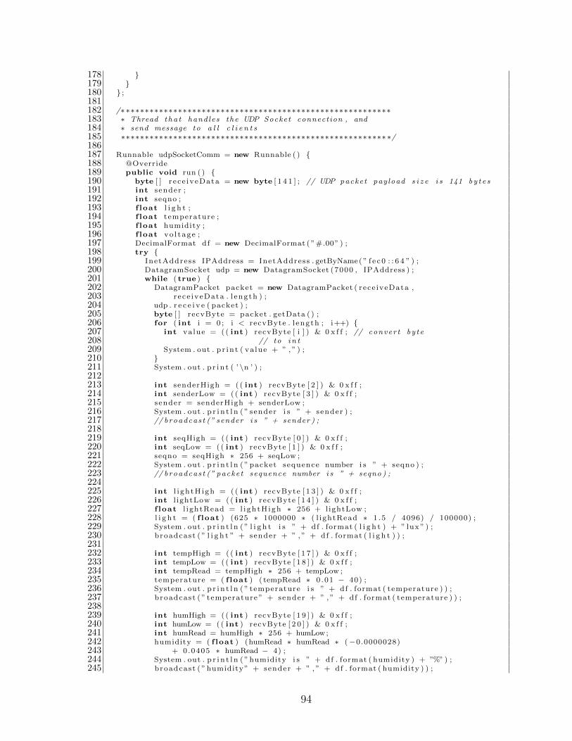
178 179 180 ;181182 /∗ ∗∗∗∗∗∗∗∗∗∗∗∗∗∗∗∗∗∗∗∗∗∗∗∗∗∗∗∗∗∗∗∗∗∗∗∗∗∗∗∗∗∗∗∗∗∗∗∗∗∗∗∗∗∗∗∗183 ∗ Thread tha t hand les the UDP Socket connection , and184 ∗ send message to a l l c l i e n t s185 ∗∗∗∗∗∗∗∗∗∗∗∗∗∗∗∗∗∗∗∗∗∗∗∗∗∗∗∗∗∗∗∗∗∗∗∗∗∗∗∗∗∗∗∗∗∗∗∗∗∗∗∗∗∗∗∗ ∗/186187 Runnable udpSocketComm = new Runnable ( ) 188 @Override189 public void run ( ) 190 byte [ ] r ece iveData = new byte [ 1 4 1 ] ; // UDP packet payload s i z e i s 141 by t e s191 int sender ;192 int seqno ;193 f loat l i g h t ;194 f loat temperature ;195 f loat humidity ;196 f loat vo l tage ;197 DecimalFormat df = new DecimalFormat ( ”#.00” ) ;198 try 199 InetAddress IPAddress = InetAddress . getByName( ” f e c 0 : : 6 4 ” ) ;200 DatagramSocket udp = new DatagramSocket (7000 , IPAddress ) ;201 while ( true ) 202 DatagramPacket packet = new DatagramPacket ( rece iveData ,203 rece iveData . l ength ) ;204 udp . r e c e i v e ( packet ) ;205 byte [ ] recvByte = packet . getData ( ) ;206 for ( int i = 0 ; i < recvByte . l ength ; i++) 207 int value = ( ( int ) recvByte [ i ] ) & 0 x f f ; // conver t by te208 // to i n t209 System . out . p r i n t ( va lue + ” , ” ) ;210 211 System . out . p r i n t ( ’ \n ’ ) ;212213 int senderHigh = ( ( int ) recvByte [ 2 ] ) & 0 x f f ;214 int senderLow = ( ( int ) recvByte [ 3 ] ) & 0 x f f ;215 sender = senderHigh + senderLow ;216 System . out . p r i n t l n ( ” sender i s ” + sender ) ;217 // broadcas t (” sender i s ” + sender ) ;218219 int seqHigh = ( ( int ) recvByte [ 0 ] ) & 0 x f f ;220 int seqLow = ( ( int ) recvByte [ 1 ] ) & 0 x f f ;221 seqno = seqHigh ∗ 256 + seqLow ;222 System . out . p r i n t l n ( ” packet sequence number i s ” + seqno ) ;223 // broadcas t (” packet sequence number i s ” + seqno ) ;224225 int l i gh tH igh = ( ( int ) recvByte [ 1 3 ] ) & 0 x f f ;226 int l ightLow = ( ( int ) recvByte [ 1 4 ] ) & 0 x f f ;227 f loat l i ghtRead = l i ghtH igh ∗ 256 + lightLow ;228 l i g h t = ( f loat ) (625 ∗ 1000000 ∗ ( l ightRead ∗ 1 .5 / 4096) / 100000) ;229 System . out . p r i n t l n ( ” l i g h t i s ” + df . format ( l i g h t ) + ” lux ” ) ;230 broadcast ( ” l i g h t ” + sender + ” , ” + df . format ( l i g h t ) ) ;231232 int tempHigh = ( ( int ) recvByte [ 1 7 ] ) & 0 x f f ;233 int tempLow = (( int ) recvByte [ 1 8 ] ) & 0 x f f ;234 int tempRead = tempHigh ∗ 256 + tempLow ;235 temperature = ( f loat ) ( tempRead ∗ 0 .01 − 40) ;236 System . out . p r i n t l n ( ” temperature i s ” + df . format ( temperature ) ) ;237 broadcast ( ” temperature ” + sender + ” , ” + df . format ( temperature ) ) ;238239 int humHigh = ( ( int ) recvByte [ 1 9 ] ) & 0 x f f ;240 int humLow = (( int ) recvByte [ 2 0 ] ) & 0 x f f ;241 int humRead = humHigh ∗ 256 + humLow;242 humidity = ( f loat ) (humRead ∗ humRead ∗ (−0.0000028)243 + 0.0405 ∗ humRead − 4) ;244 System . out . p r i n t l n ( ”humidity i s ” + df . format ( humidity ) + ”%” ) ;245 broadcast ( ”humidity” + sender + ” , ” + df . format ( humidity ) ) ;
94

246247 int volHigh = ( ( int ) recvByte [ 2 1 ] ) & 0 x f f ;248 int volLow = ( ( int ) recvByte [ 2 2 ] ) & 0 x f f ;249 f loat volRead = volHigh ∗ 256 + volLow ;250 vo l tage = volRead ∗ 3 / 4096 ;251 System . out . p r i n t l n ( ” vo l tage i s ” + df . format ( vo l tage ) + ”V” ) ;252 broadcast ( ” vo l tage ” + sender + ” , ” + df . format ( vo l tage ) ) ;253 254 catch ( UnknownHostException e ) 255 // TODO Auto−generated catch b l o c k256 e . pr intStackTrace ( ) ;257 catch ( SocketExcept ion e ) 258 // TODO Auto−generated catch b l o c k259 e . pr intStackTrace ( ) ;260 catch ( IOException e ) 261 // TODO Auto−generated catch b l o c k262 e . pr intStackTrace ( ) ;263 264 265 ;266267 public WsnWebSocketHandler ( ) 268 super ( ) ;269 Thread tcpSocketThread = new Thread ( tcpSocketComm) ;270 tcpSocketThread . s t a r t ( ) ;271 Thread udpSocketThread = new Thread (udpSocketComm) ;272 udpSocketThread . s t a r t ( ) ;273 274275 public WebSocket doWebSocketConnect ( HttpServ letRequest request ,276 St r ing p ro to co l ) 277 return new WsnWebSocket ( ) ;278 279280 private class WsnWebSocket implements WebSocket . OnTextMessage 281282 private Connection connect ion ;283284 public void onOpen( Connection connect ion ) 285 // C l i en t (Browser ) WebSockets has opened a connect ion .286 // 1) Store the opened connect ion287 this . connect ion = connect ion ;288 // 2) Add WsnWebSocket in the g l o b a l l i s t o f WsnWebSocket289 // ins tance s290 // ins tance .291 webSockets . add ( this ) ;292 293294 public void onMessage ( S t r ing data ) 295 // Loop fo r each ins tance o f WsnWebSocket to send message se rve r to296 // each c l i e n t WebSockets .297 try 298 for (WsnWebSocket webSocket : webSockets ) 299 // send a message to the current c l i e n t WebSocket .300 webSocket . connect ion . sendMessage ( data ) ;301 302 catch ( IOException x ) 303 // Error was de tec ted , c l o s e the WsnWebSocket c l i e n t s i d e304 this . connect ion . c l o s e ( ) ;305 306 307308 public void onClose ( int closeCode , S t r ing message ) 309 // Remove WsnWebSocket in the g l o b a l l i s t o f WsnWebSocket310 // ins tance .311 webSockets . remove ( this ) ;312 313
95
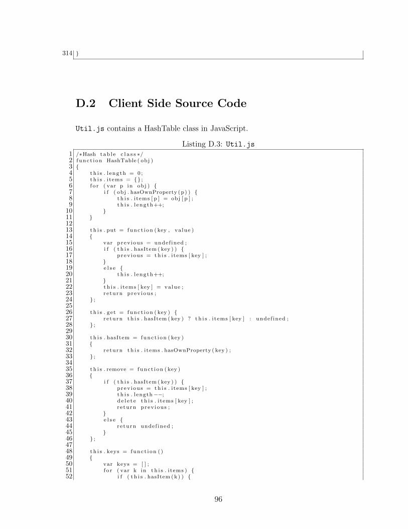
314
D.2 Client Side Source Code
Util.js contains a HashTable class in JavaScript.
Listing D.3: Util.js1 /∗Hash tab l e c l a s s ∗/2 f unc t i on HashTable ( obj )3 4 t h i s . l ength = 0 ;5 t h i s . i tems = ;6 f o r ( var p in obj ) 7 i f ( obj . hasOwnProperty (p) ) 8 t h i s . i tems [ p ] = obj [ p ] ;9 t h i s . l ength++;10 11 1213 t h i s . put = func t i on ( key , va lue )14 15 var prev ious = undef ined ;16 i f ( t h i s . hasItem ( key ) ) 17 prev ious = th i s . i tems [ key ] ;18 19 e l s e 20 t h i s . l ength++;21 22 t h i s . i tems [ key ] = value ;23 r e turn prev ious ;24 ;2526 t h i s . get = func t i on ( key ) 27 r e turn t h i s . hasItem ( key ) ? t h i s . i tems [ key ] : undef ined ;28 ;2930 t h i s . hasItem = func t i on ( key )31 32 r e turn t h i s . i tems . hasOwnProperty ( key ) ;33 ;3435 t h i s . remove = func t i on ( key )36 37 i f ( t h i s . hasItem ( key ) ) 38 prev ious = th i s . i tems [ key ] ;39 t h i s . length−−;40 de l e t e t h i s . i tems [ key ] ;41 r e turn prev ious ;42 43 e l s e 44 r e turn undef ined ;45 46 ;4748 t h i s . keys = func t i on ( )49 50 var keys = [ ] ;51 f o r ( var k in t h i s . i tems ) 52 i f ( t h i s . hasItem (k ) )
96

53 keys . push (k ) ;54 55 56 r e turn keys ;57 ;5859 t h i s . va lue s = func t i on ( )60 61 var va lue s = [ ] ;62 f o r ( var k in t h i s . i tems ) 63 i f ( t h i s . hasItem (k ) ) 64 va lue s . push ( t h i s . i tems [ k ] ) ;65 66 67 r e turn va lue s ;68 ;6970 t h i s . each = func t i on ( fn ) 71 f o r ( var k in t h i s . i tems ) 72 i f ( t h i s . hasItem (k ) ) 73 fn (k , t h i s . i tems [ k ] ) ;74 75 76 ;7778 t h i s . c l e a r = func t i on ( )79 80 t h i s . i tems = ;81 t h i s . l ength = 0 ;82 ;83
wsn.html is the user interface of WSNWeb application, which contains the code
for receiving route topology and sensor readings information from the server and
animation.
Listing D.4: wsn.html1 <html xmlns=”http ://www.w3 . org /1999/ xhtml”2 xmlns : svg=”http ://www.w3 . org /2000/ svg”3 xmlns : vml=”urn : schemas−microso f t−com : vml”>4 <head>5 <t i t l e>WSN Web</ t i t l e>6 <l ink href=” s t y l e . c s s ” rel=” s t y l e s h e e t ” type=” text / c s s ” media=” sc r een ” />7 <script type=” text / j a v a s c r i p t ” src=” ./ j s g l . min . j s ”></ script>8 <script type=” text / j a v a s c r i p t ” src=”Ut i l . j s ”></ script>9 </head>10 <body>11 <div id=”wrapper”>12 <div id=”header ” class=” conta ine r ”>13 <div id=” logo ”>14 <img src=” images /UNBlogo . png” alt=”UNB Logo” width=”260” height=”90” />15 </div>16 <div id=”menu”>17 <ul>18 < l i><a href=”http : / /131 . 2 02 . 2 43 . 6 : 8 080/HomePage”>Homepage</a></ l i>19 < l i><a href=”http : / /131 . 2 02 . 2 43 . 6 : 8 080/WSNWeb”>WSNWeb</a></ l i>20 </ul>21 </div>22 </div>23 <div id=” app t i t l e ”>24 <h1 class=” b lock t ex t ”>Mobile Sensor Network Communication</h1>2526 </div>27
97

28 < !−− end #header −−>29 <div id=”Page”>30 <div id=” textFieldWrapper ”>31 <font color=”white ” s ize=”4”>Dynamic update o f new route s</ font>32 <div id=” t ex tF i e l d ”></div>33 </div>34 <div id=”sensorReadingsWrapper ”>35 <font color=”white ” s ize=”4”>Sensor r ead ings</ font>36 <div id=” sensorReadings ”>37 <div id=”node1”>38 <label id=”node1 labe l ”>node 0x1</ label>39 <div id=”node1temperature ”>40 <font color=”white ”>temperature</ font>41 <div id=”temperatureValue1 ”></div>42 </div>43 <div id=”node1humidity”>44 <font color=”white ”>humidity</ font>45 <div id=”humidityValue1”></div>46 </div>47 <div id=” node1 l i gh t ”>48 <font color=”white ”> l i g h t</ font>49 <div id=” l i ghtVa lue1 ”></div>50 </div>51 <div id=”node1voltage ”>52 <font color=”white ”>vo l tage</ font>53 <div id=”voltageValue1 ”></div>54 </div>55 </div>56 <div id=”node8”>57 <label id=”node8 labe l ”>node 0x8</ label>58 <div id=”node8temperature ”>59 <font color=”white ”>temperature</ font>60 <div id=”temperatureValue8 ”></div>61 </div>62 <div id=”node8humidity”>63 <font color=”white ”>humidity</ font>64 <div id=”humidityValue8”></div>65 </div>66 <div id=” node8 l i gh t ”>67 <font color=”white ”> l i g h t</ font>68 <div id=” l i ghtVa lue8 ”></div>69 </div>70 <div id=”node8voltage ”>71 <font color=”white ”>vo l tage</ font>72 <div id=”voltageValue8 ”></div>73 </div>74 </div>75 </div>76 <div id=”parameterPanel ”>77 <h1>WSN parameters</h1>78 <p>power l e v e l : −25dBm <br><br>79 RTUP: 0 .6 seconds<br><br>80 Speed s t ep s : 80</p>81 </div>82 </div>83 <div id=”canvasFieldWrapper ”>84 <font color=”white ” s ize=”4”>WSN tes tbed in ITB214 lab</ font>85 <div id=” canvasFie ld ”>86 <canvas id=”nodeCanvas” width=”400” height=”500”></ canvas>87 < !−− canvas id=” l ineCanvas ” width=”600” height=”400”></ canvas> −−>88 </div>89 <div id=” toggleButton ”>90 <button id=” togg leBt ” type=”button” onclick=” togg leRoutes ( ) ”>show91 s t a t i ona ry nodes route s</button>92 </div>93 </div>9495 </div>
98
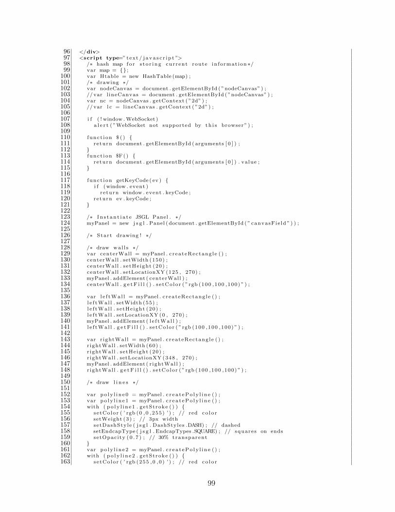
96 </div>97 <script type=” text / j a v a s c r i p t ”>98 /∗ hash map f o r s t o r i n g cur rent route in fo rmat ion ∗/99 var map = ;
100 var Htable = new HashTable (map) ;101 /∗ drawing ∗/102 var nodeCanvas = document . getElementById ( ”nodeCanvas” ) ;103 // var l ineCanvas = document . getElementById ( ”nodeCanvas” ) ;104 var nc = nodeCanvas . getContext ( ”2d” ) ;105 // var l c = l ineCanvas . getContext ( ”2d” ) ;106107 i f ( ! window .WebSocket )108 a l e r t ( ”WebSocket not supported by t h i s browser ” ) ;109110 f unc t i on $ ( ) 111 r e turn document . getElementById ( arguments [ 0 ] ) ;112 113 f unc t i on $F ( ) 114 r e turn document . getElementById ( arguments [ 0 ] ) . va lue ;115 116117 f unc t i on getKeyCode ( ev ) 118 i f (window . event )119 r e turn window . event . keyCode ;120 r e turn ev . keyCode ;121 122123 /∗ I n s t a n t i a t e JSGL Panel . ∗/124 myPanel = new j s g l . Panel ( document . getElementById ( ” canvasFie ld ” ) ) ;125126 /∗ Star t drawing ! ∗/127128 /∗ draw wa l l s ∗/129 var centerWal l = myPanel . c r ea t eRec tang l e ( ) ;130 centerWal l . setWidth (150) ;131 centerWal l . s e tHe ight (20) ;132 centerWal l . setLocationXY (125 , 270) ;133 myPanel . addElement ( centerWal l ) ;134 centerWal l . g e t F i l l ( ) . s e tCo lo r ( ” rgb (100 ,100 ,100) ” ) ;135136 var l e f tWa l l = myPanel . c r ea t eRec tang l e ( ) ;137 l e f tWa l l . setWidth (55) ;138 l e f tWa l l . s e tHe ight (20) ;139 l e f tWa l l . setLocationXY (0 , 270) ;140 myPanel . addElement ( l e f tWa l l ) ;141 l e f tWa l l . g e t F i l l ( ) . s e tCo lo r ( ” rgb (100 ,100 ,100) ” ) ;142143 var r ightWal l = myPanel . c r ea t eRec tang l e ( ) ;144 r ightWal l . setWidth (60) ;145 r ightWal l . s e tHe ight (20) ;146 r ightWal l . setLocationXY (348 , 270) ;147 myPanel . addElement ( r ightWal l ) ;148 r ightWal l . g e t F i l l ( ) . s e tCo lo r ( ” rgb (100 ,100 ,100) ” ) ;149150 /∗ draw l i n e s ∗/151152 var po l y l i n e 0 = myPanel . c r e a t ePo l y l i n e ( ) ;153 var po l y l i n e 1 = myPanel . c r e a t ePo l y l i n e ( ) ;154 with ( po l y l i n e 1 . ge tSt roke ( ) ) 155 s e tCo lo r ( ’ rgb (0 ,0 , 255 ) ’ ) ; // red c o l o r156 setWeight (3 ) ; // 3px width157 setDashSty le ( j s g l . DashStyles .DASH) ; // dashed158 setEndcapType ( j s g l . EndcapTypes .SQUARE) ; // squares on ends159 setOpac i ty ( 0 . 7 ) ; // 30% transparent160 161 var po l y l i n e 2 = myPanel . c r e a t ePo l y l i n e ( ) ;162 with ( po l y l i n e 2 . ge tSt roke ( ) ) 163 s e tCo lo r ( ’ rgb (255 ,0 , 0 ) ’ ) ; // red c o l o r
99

164 setWeight (2 ) ; // 2px width165 setDashSty le ( j s g l . DashStyles .DASH) ; // dashed166 setEndcapType ( j s g l . EndcapTypes .SQUARE) ; // squares on ends167 setOpac i ty ( 0 . 5 ) ; // 50% transparent168 169 var po l y l i n e 3 = myPanel . c r e a t ePo l y l i n e ( ) ;170 with ( po l y l i n e 3 . ge tSt roke ( ) ) 171 s e tCo lo r ( ’ rgb (255 ,0 , 0 ) ’ ) ; // red c o l o r172 setWeight (2 ) ; // 2px width173 setDashSty le ( j s g l . DashStyles .DASH) ; // dashed174 setEndcapType ( j s g l . EndcapTypes .SQUARE) ; // squares on ends175 setOpac i ty ( 0 . 5 ) ; // 50% transparent176 177 var po l y l i n e 4 = myPanel . c r e a t ePo l y l i n e ( ) ;178 with ( po l y l i n e 4 . ge tSt roke ( ) ) 179 s e tCo lo r ( ’ rgb (255 ,0 , 0 ) ’ ) ; // red c o l o r180 setWeight (2 ) ; // 2px width181 setDashSty le ( j s g l . DashStyles .DASH) ; // dashed182 setEndcapType ( j s g l . EndcapTypes .SQUARE) ; // squares on ends183 setOpac i ty ( 0 . 5 ) ; // 50% transparent184 185 var po l y l i n e 5 = myPanel . c r e a t ePo l y l i n e ( ) ;186 with ( po l y l i n e 5 . ge tSt roke ( ) ) 187 s e tCo lo r ( ’ rgb (255 ,0 , 0 ) ’ ) ; // red c o l o r188 setWeight (2 ) ; // 2px width189 setDashSty le ( j s g l . DashStyles .DASH) ; // dashed190 setEndcapType ( j s g l . EndcapTypes .SQUARE) ; // squares on ends191 setOpac i ty ( 0 . 5 ) ; // 50% transparent192 193 var po l y l i n e 6 = myPanel . c r e a t ePo l y l i n e ( ) ;194 with ( po l y l i n e 6 . ge tSt roke ( ) ) 195 s e tCo lo r ( ’ rgb (255 ,0 , 0 ) ’ ) ; // red c o l o r196 setWeight (2 ) ; // 2px width197 setDashSty le ( j s g l . DashStyles .DASH) ; // dashed198 setEndcapType ( j s g l . EndcapTypes .SQUARE) ; // squares on ends199 setOpac i ty ( 0 . 5 ) ; // 50% transparent200 201 var po l y l i n e 7 = myPanel . c r e a t ePo l y l i n e ( ) ;202 with ( po l y l i n e 7 . ge tSt roke ( ) ) 203 s e tCo lo r ( ’ rgb (255 ,0 , 0 ) ’ ) ; // red c o l o r204 setWeight (2 ) ; // 2px width205 setDashSty le ( j s g l . DashStyles .DASH) ; // dashed206 setEndcapType ( j s g l . EndcapTypes .SQUARE) ; // squares on ends207 setOpac i ty ( 0 . 5 ) ; // 50% transparent208 209 var po l y l i n e 8 = myPanel . c r e a t ePo l y l i n e ( ) ;210 with ( po l y l i n e 8 . ge tSt roke ( ) ) 211 s e tCo lo r ( ’ rgb (0 ,0 , 255 ) ’ ) ; // red c o l o r212 setWeight (3 ) ; // 3px width213 setDashSty le ( j s g l . DashStyles .DASH) ; // dashed214 setEndcapType ( j s g l . EndcapTypes .SQUARE) ; // squares on ends215 setOpac i ty ( 0 . 7 ) ; // 30% transparent216 217218 var p o l y l i n e s = new Array ( ) ;219 p o l y l i n e s . push ( po l y l i n e 0 ) ; // fake p o l y l i n e220 p o l y l i n e s . push ( po l y l i n e 1 ) ;221 p o l y l i n e s . push ( po l y l i n e 2 ) ;222 p o l y l i n e s . push ( po l y l i n e 3 ) ;223 p o l y l i n e s . push ( po l y l i n e 4 ) ;224 p o l y l i n e s . push ( po l y l i n e 5 ) ;225 p o l y l i n e s . push ( po l y l i n e 6 ) ;226 p o l y l i n e s . push ( po l y l i n e 7 ) ;227 p o l y l i n e s . push ( po l y l i n e 8 ) ;228229 myPanel . addElement ( po l y l i n e 1 ) ;230 /∗231 myPanel . addElement ( po l y l i n e 2 ) ;
100

232 myPanel . addElement ( po l y l i n e 3 ) ;233 myPanel . addElement ( po l y l i n e 4 ) ;234 myPanel . addElement ( po l y l i n e 5 ) ;235 myPanel . addElement ( po l y l i n e 6 ) ;236 myPanel . addElement ( po l y l i n e 7 ) ;237 ∗/238 myPanel . addElement ( po l y l i n e 8 ) ;239240 /∗ Draw s t a t i ona ry nodes ∗/241 node2 = myPanel . c r e a t eC i r c l e ( ) ;242 node2 . setCenterLocationXY (20 , 20) ;243 node2 . setRadius (5 ) ;244 node2 . ge tSt roke ( ) . setWeight (5 ) ;245 node2 . ge tSt roke ( ) . s e tCo lo r ( ” rgb (255 ,0 , 0 ) ” ) ;246 myPanel . addElement ( node2 ) ;247248 node3 = myPanel . c r e a t eC i r c l e ( ) ;249 node3 . setCenterLocationXY (380 , 20) ;250 node3 . setRadius (5 ) ;251 node3 . ge tSt roke ( ) . setWeight (5 ) ;252 node3 . ge tSt roke ( ) . s e tCo lo r ( ” rgb (255 ,0 , 0 ) ” ) ;253 myPanel . addElement ( node3 ) ;254255 node4 = myPanel . c r e a t eC i r c l e ( ) ;256 node4 . setCenterLocationXY (20 , 250) ;257 node4 . setRadius (5 ) ;258 node4 . ge tSt roke ( ) . setWeight (5 ) ;259 node4 . ge tSt roke ( ) . s e tCo lo r ( ” rgb (255 ,0 , 0 ) ” ) ;260 myPanel . addElement ( node4 ) ;261262 node5 = myPanel . c r e a t eC i r c l e ( ) ;263 node5 . setCenterLocationXY (380 , 250) ;264 node5 . setRadius (5 ) ;265 node5 . ge tSt roke ( ) . setWeight (5 ) ;266 node5 . ge tSt roke ( ) . s e tCo lo r ( ” rgb (255 ,0 , 0 ) ” ) ;267 myPanel . addElement ( node5 ) ;268269 node6 = myPanel . c r e a t eC i r c l e ( ) ;270 node6 . setCenterLocationXY (20 , 480) ;271 node6 . setRadius (5 ) ;272 node6 . ge tSt roke ( ) . setWeight (5 ) ;273 node6 . ge tSt roke ( ) . s e tCo lo r ( ” rgb (255 ,0 , 0 ) ” ) ;274 myPanel . addElement ( node6 ) ;275276 node7 = myPanel . c r e a t eC i r c l e ( ) ;277 node7 . setCenterLocationXY (380 , 480) ;278 node7 . setRadius (5 ) ;279 node7 . ge tSt roke ( ) . setWeight (5 ) ;280 node7 . ge tSt roke ( ) . s e tCo lo r ( ” rgb (255 ,0 , 0 ) ” ) ;281 myPanel . addElement ( node7 ) ;282283 /∗ Draw moving nodes ∗/284285 node1 = myPanel . c r e a t eC i r c l e ( ) ;286 node1 . setRadius (5 ) ;287 node1 . ge tSt roke ( ) . setWeight (5 ) ;288 node1 . ge tSt roke ( ) . s e tCo lo r ( ” rgb (0 ,0 , 255 ) ” ) ;289 myPanel . addElement ( node1 ) ;290291 node8 = myPanel . c r e a t eC i r c l e ( ) ;292 node8 . setRadius (5 ) ;293 node8 . ge tSt roke ( ) . setWeight (5 ) ;294 node8 . ge tSt roke ( ) . s e tCo lo r ( ” rgb (0 ,255 ,0 ) ” ) ;295 myPanel . addElement ( node8 ) ;296297 /∗ Draw edge route r 0x64 ∗/298 node0 = myPanel . c r e a t eC i r c l e ( ) ;299 node0 . setCenterLocationXY (50 , 250) ;
101
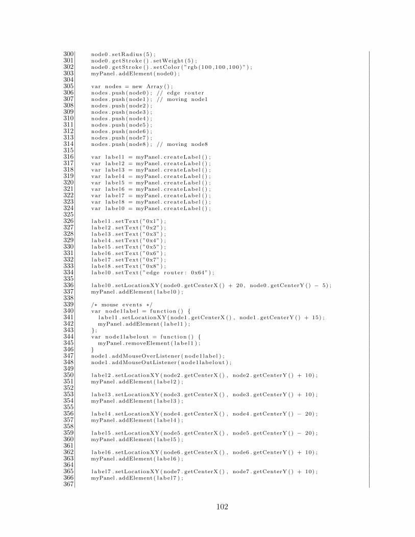
300 node0 . setRadius (5 ) ;301 node0 . ge tSt roke ( ) . setWeight (5 ) ;302 node0 . ge tSt roke ( ) . s e tCo lo r ( ” rgb (100 ,100 ,100) ” ) ;303 myPanel . addElement ( node0 ) ;304305 var nodes = new Array ( ) ;306 nodes . push ( node0 ) ; // edge route r307 nodes . push ( node1 ) ; // moving node1308 nodes . push ( node2 ) ;309 nodes . push ( node3 ) ;310 nodes . push ( node4 ) ;311 nodes . push ( node5 ) ;312 nodes . push ( node6 ) ;313 nodes . push ( node7 ) ;314 nodes . push ( node8 ) ; // moving node8315316 var l a b e l 1 = myPanel . c r ea t eLabe l ( ) ;317 var l a b e l 2 = myPanel . c r ea t eLabe l ( ) ;318 var l a b e l 3 = myPanel . c r ea t eLabe l ( ) ;319 var l a b e l 4 = myPanel . c r ea t eLabe l ( ) ;320 var l a b e l 5 = myPanel . c r ea t eLabe l ( ) ;321 var l a b e l 6 = myPanel . c r ea t eLabe l ( ) ;322 var l a b e l 7 = myPanel . c r ea t eLabe l ( ) ;323 var l a b e l 8 = myPanel . c r ea t eLabe l ( ) ;324 var l a b e l 0 = myPanel . c r ea t eLabe l ( ) ;325326 l a b e l 1 . setText ( ”0x1” ) ;327 l a b e l 2 . setText ( ”0x2” ) ;328 l a b e l 3 . setText ( ”0x3” ) ;329 l a b e l 4 . setText ( ”0x4” ) ;330 l a b e l 5 . setText ( ”0x5” ) ;331 l a b e l 6 . setText ( ”0x6” ) ;332 l a b e l 7 . setText ( ”0x7” ) ;333 l a b e l 8 . setText ( ”0x8” ) ;334 l a b e l 0 . setText ( ” edge route r : 0x64” ) ;335336 l a b e l 0 . setLocationXY ( node0 . getCenterX ( ) + 20 , node0 . getCenterY ( ) − 5) ;337 myPanel . addElement ( l a b e l 0 ) ;338339 /∗ mouse events ∗/340 var node1 labe l = func t i on ( ) 341 l a b e l 1 . setLocationXY ( node1 . getCenterX ( ) , node1 . getCenterY ( ) + 15) ;342 myPanel . addElement ( l a b e l 1 ) ;343 ;344 var node1 labe lout = func t i on ( ) 345 myPanel . removeElement ( l a b e l 1 ) ;346 347 node1 . addMouseOverListener ( node1 labe l ) ;348 node1 . addMouseOutListener ( node1 labe lout ) ;349350 l a b e l 2 . setLocationXY ( node2 . getCenterX ( ) , node2 . getCenterY ( ) + 10) ;351 myPanel . addElement ( l a b e l 2 ) ;352353 l a b e l 3 . setLocationXY ( node3 . getCenterX ( ) , node3 . getCenterY ( ) + 10) ;354 myPanel . addElement ( l a b e l 3 ) ;355356 l a b e l 4 . setLocationXY ( node4 . getCenterX ( ) , node4 . getCenterY ( ) − 20) ;357 myPanel . addElement ( l a b e l 4 ) ;358359 l a b e l 5 . setLocationXY ( node5 . getCenterX ( ) , node5 . getCenterY ( ) − 20) ;360 myPanel . addElement ( l a b e l 5 ) ;361362 l a b e l 6 . setLocationXY ( node6 . getCenterX ( ) , node6 . getCenterY ( ) + 10) ;363 myPanel . addElement ( l a b e l 6 ) ;364365 l a b e l 7 . setLocationXY ( node7 . getCenterX ( ) , node7 . getCenterY ( ) + 10) ;366 myPanel . addElement ( l a b e l 7 ) ;367
102

368 var node8 labe l = func t i on ( ) 369 l a b e l 8 . setLocationXY ( node8 . getCenterX ( ) , node8 . getCenterY ( ) + 15) ;370 myPanel . addElement ( l a b e l 8 ) ;371 ;372 var node8 labe lout = func t i on ( ) 373 myPanel . removeElement ( l a b e l 8 ) ;374 375 node8 . addMouseOverListener ( node8 labe l ) ;376 node8 . addMouseOutListener ( node8 labe lout ) ;377378 /∗ Animator ∗/379380 var animator11 = new j s g l . u t i l . Animator ( ) ; /∗ node1 animator ∗/381 var animator12 = new j s g l . u t i l . Animator ( ) ;382 var animator13 = new j s g l . u t i l . Animator ( ) ;383 var animator14 = new j s g l . u t i l . Animator ( ) ;384 var animator15 = new j s g l . u t i l . Animator ( ) ;385 var animator16 = new j s g l . u t i l . Animator ( ) ;386 var animator17 = new j s g l . u t i l . Animator ( ) ;387 var animator18 = new j s g l . u t i l . Animator ( ) ;388389 /∗ Animator ∗/390391 var animator81 = new j s g l . u t i l . Animator ( ) ; /∗ node8 animator ∗/392 var animator82 = new j s g l . u t i l . Animator ( ) ;393 var animator83 = new j s g l . u t i l . Animator ( ) ;394 var animator84 = new j s g l . u t i l . Animator ( ) ;395 var animator85 = new j s g l . u t i l . Animator ( ) ;396 var animator86 = new j s g l . u t i l . Animator ( ) ;397 var animator87 = new j s g l . u t i l . Animator ( ) ;398 var animator88 = new j s g l . u t i l . Animator ( ) ;399400 var shortDurat ion1 = 4000 ;401 var speed1 = 120 / 4000 ;402 var longDurat ion1 = 250 / speed1 ;403 var curveDuration1 = 0.25 ∗ 2 ∗ Math . PI ∗ 50 / speed1 ;404405 var speed8 = speed1 / 1 . 2 5 ;406 var shortDurat ion8 = 170 / speed8 ;407 var longDurat ion8 = 300 / speed8 ;408 var curveDuration8 = 0.25 ∗ 2 ∗ Math . PI ∗ 50 / speed8 ;409410 /∗ node1 moving ∗/411 animator11 . s e tS ta r tVa lue (1 ∗ Math . PI ) ; // l e f t top curve412 animator11 . setEndValue ( 1 . 5 ∗ Math . PI ) ;413 animator11 . setDurat ion ( curveDuration1 ) ;414 animator11 . setRepeat ing ( t rue ) ;415416 animator12 . s e tS ta r tVa lue (0 ) ; // top shor t s i d e417 animator12 . setEndValue (120) ;418 animator12 . setDurat ion ( shortDurat ion1 ) ;419 animator12 . setRepeat ing ( t rue ) ;420421 animator13 . s e tS ta r tVa lue ( 1 . 5 ∗ Math . PI ) ; // r i g h t top curve422 animator13 . setEndValue (2 ∗ Math . PI ) ;423 animator13 . setDurat ion ( curveDuration1 ) ;424 animator13 . setRepeat ing ( t rue ) ;425426 animator14 . s e tS ta r tVa lue (0 ) ; // r i g h t long s i d e427 // animator14 . setEndValue (220) ;428 animator14 . setEndValue (250) ;429 animator14 . setDurat ion ( longDurat ion1 ) ;430 animator14 . setRepeat ing ( t rue ) ;431432 animator15 . s e tS ta r tVa lue (0 ∗ Math . PI ) ; // r i g h t bottom curve433 animator15 . setEndValue ( 0 . 5 ∗ Math . PI ) ;434 animator15 . setDurat ion ( curveDuration1 ) ;435 animator15 . setRepeat ing ( t rue ) ;
103

436437 animator16 . s e tS ta r tVa lue (0 ) ; // bottom shor t s i d e438 animator16 . setEndValue (120) ;439 animator16 . setDurat ion ( shortDurat ion1 ) ;440 animator16 . setRepeat ing ( t rue ) ;441442 animator17 . s e tS ta r tVa lue ( 0 . 5 ∗ Math . PI ) ; // l e f t bottom curve443 animator17 . setEndValue (1 ∗ Math . PI ) ;444 animator17 . setDurat ion ( curveDuration1 ) ;445 animator17 . setRepeat ing ( t rue ) ;446447 animator18 . s e tS ta r tVa lue (0 ) ; // l e f t long s i d e448 // animator18 . setEndValue (220) ;449 animator18 . setEndValue (250) ;450 animator18 . setDurat ion ( longDurat ion1 ) ;451 animator18 . setRepeat ing ( t rue ) ;452453 /∗ node8 moving ∗/454 animator81 . s e tS ta r tVa lue ( 0 . 5 ∗ Math . PI ) ; // r i g h t bottom curve455 animator81 . setEndValue (0 ∗ Math . PI ) ;456 animator81 . setDurat ion ( curveDuration8 ) ;457 animator81 . setRepeat ing ( t rue ) ;458459 animator82 . s e tS ta r tVa lue (0 ) ; // r i g h t long s i d e460 // animator82 . setEndValue (270) ;461 animator82 . setEndValue (300) ;462 animator82 . setDurat ion ( longDurat ion8 ) ;463 animator82 . setRepeat ing ( t rue ) ;464465 animator83 . s e tS ta r tVa lue (2 ∗ Math . PI ) ; // r i g h t top curve466 animator83 . setEndValue ( 1 . 5 ∗ Math . PI ) ;467 animator83 . setDurat ion ( curveDuration8 ) ;468 animator83 . setRepeat ing ( t rue ) ;469470 animator84 . s e tS ta r tVa lue (0 ) ; // top shor t s i d e471 animator84 . setEndValue (170) ;472 animator84 . setDurat ion ( shortDurat ion8 ) ;473 animator84 . setRepeat ing ( t rue ) ;474475 animator85 . s e tS ta r tVa lue ( 1 . 5 ∗ Math . PI ) ; // l e f t top curve476 animator85 . setEndValue (1 ∗ Math . PI ) ;477 animator85 . setDurat ion ( curveDuration8 ) ;478 animator85 . setRepeat ing ( t rue ) ;479480 animator86 . s e tS ta r tVa lue (0 ) ; // l e f t long s i d e481 // animator86 . setEndValue (270) ;482 animator86 . setEndValue (300) ;483 animator86 . setDurat ion ( longDurat ion8 ) ;484 animator86 . setRepeat ing ( t rue ) ;485486 animator87 . s e tS ta r tVa lue (1 ∗ Math . PI ) ; // l e f t bottom curve487 animator87 . setEndValue ( 0 . 5 ∗ Math . PI ) ;488 animator87 . setDurat ion ( curveDuration8 ) ;489 animator87 . setRepeat ing ( t rue ) ;490491 animator88 . s e tS ta r tVa lue (0 ) ; // bottom shor t s i d e492 animator88 . setEndValue (170) ;493 animator88 . setDurat ion ( shortDurat ion8 ) ;494 animator88 . setRepeat ing ( t rue ) ;495496 var l ineAnimator = new j s g l . u t i l . Animator ( ) ; // l i n e497 l ineAnimator . se tRepeat ing ( t rue ) ;498499 /∗ animation play ∗/500 /∗ node1 ∗/501 animator11 . addEndListener ( func t i on ( ) 502 animator11 . pause ( ) ;503 animator12 . play ( ) ;
104

504 ) ;505506 animator12 . addEndListener ( func t i on ( ) 507 animator12 . pause ( ) ;508 animator13 . play ( ) ;509 ) ;510511 animator13 . addEndListener ( func t i on ( ) 512 animator13 . pause ( ) ;513 animator14 . play ( ) ;514 ) ;515516 animator14 . addEndListener ( func t i on ( ) 517 animator14 . pause ( ) ;518 animator15 . play ( ) ;519 ) ;520521 animator15 . addEndListener ( func t i on ( ) 522 animator15 . pause ( ) ;523 animator16 . play ( ) ;524 ) ;525526 animator16 . addEndListener ( func t i on ( ) 527 animator16 . pause ( ) ;528 animator17 . play ( ) ;529 ) ;530531 animator17 . addEndListener ( func t i on ( ) 532 animator17 . pause ( ) ;533 animator18 . play ( ) ;534 ) ;535536 animator18 . addEndListener ( func t i on ( ) 537 animator18 . pause ( ) ;538 animator11 . play ( ) ;539 ) ;540541 /∗ node8 ∗/542 animator81 . addEndListener ( func t i on ( ) 543 animator81 . pause ( ) ;544 animator82 . play ( ) ;545 ) ;546547 animator82 . addEndListener ( func t i on ( ) 548 animator82 . pause ( ) ;549 animator83 . play ( ) ;550 ) ;551552 animator83 . addEndListener ( func t i on ( ) 553 animator83 . pause ( ) ;554 animator84 . play ( ) ;555 ) ;556557 animator84 . addEndListener ( func t i on ( ) 558 animator84 . pause ( ) ;559 animator85 . play ( ) ;560 ) ;561562 animator85 . addEndListener ( func t i on ( ) 563 animator85 . pause ( ) ;564 animator86 . play ( ) ;565 ) ;566567 animator86 . addEndListener ( func t i on ( ) 568 animator86 . pause ( ) ;569 animator87 . play ( ) ;570 ) ;571
105

572 animator87 . addEndListener ( func t i on ( ) 573 animator87 . pause ( ) ;574 animator88 . play ( ) ;575 ) ;576577 animator88 . addEndListener ( func t i on ( ) 578 animator88 . pause ( ) ;579 animator81 . play ( ) ;580 ) ;581582 var po ly l ine sNodes = new Array (8 ) ; // s t o r e nodes o f each po l y l i n e583 f o r ( var i = 0 ; i < 8 ; i++) // 0 to 7 are p o l y l i n e s 1 to 8584 po ly l ine sNodes [ i ] = new Array (9 ) ;585 for ( var j = 0 ; j < 9 ; j++)586 po ly l ine sNodes [ i ] [ j ] = −1;587 588589 l ineAnimator . addStepLis tener ( func t i on ( t ) // l i n e−moving l i s t e n e r590 for ( var i = 1 ; i < p o l y l i n e s . l ength ; i++) 591 for ( var j = 0 ; j < p o l y l i n e s [ i ] . getPointsCount ( ) ; j++) 592 p o l y l i n e s [ i ] . setPointXYAt ( nodes [ po ly l ine sNodes [ i − 1 ] [ j ] ]593 . getCenterX ( ) , nodes [ po ly l ine sNodes [ i − 1 ] [ j ] ]594 . getCenterY ( ) , j ) ;595 596 597 ) ;598599 /∗ node1 ∗/600 animator11 . addStepLis tener ( func t i on ( t ) // l e f t top curve601 node1 . setCenterX (140 + 50 ∗ Math . cos ( t ) ) ;602 node1 . setCenterY (125 + 50 ∗ Math . s i n ( t ) ) ;603 ) ;604605 animator12 . addStepLis tener ( func t i on ( t ) // top shor t s i d e606 node1 . setCenterX (140 + t ) ;607 node1 . setCenterY (75) ;608 ) ;609610 animator13 . addStepLis tener ( func t i on ( t ) // r i gh t top curve611 node1 . setCenterX (260 + 50 ∗ Math . cos ( t ) ) ;612 node1 . setCenterY (125 + 50 ∗ Math . s i n ( t ) ) ;613 ) ;614615 animator14 . addStepLis tener ( func t i on ( t ) // r i gh t long s i d e616 node1 . setCenterX (310) ;617 node1 . setCenterY (125 + t ) ;618 ) ;619620 animator15 . addStepLis tener ( func t i on ( t ) // r i gh t bottom curve621 node1 . setCenterX (260 + 50 ∗ Math . cos ( t ) ) ;622 node1 . setCenterY (375 + 50 ∗ Math . s i n ( t ) ) ;623 ) ;624625 animator16 . addStepLis tener ( func t i on ( t ) // bottom shor t s i d e626 node1 . setCenterX (260 − t ) ;627 node1 . setCenterY (425) ;628 ) ;629630 animator17 . addStepLis tener ( func t i on ( t ) // l e f t bottom curve631 node1 . setCenterX (140 + 50 ∗ Math . cos ( t ) ) ;632 node1 . setCenterY (375 + 50 ∗ Math . s i n ( t ) ) ;633 ) ;634635 animator18 . addStepLis tener ( func t i on ( t ) // l e f t long s i d e636 node1 . setCenterX (90) ;637 node1 . setCenterY (375 − t ) ;638 ) ;639
106

640 /∗ node8 ∗/641 animator81 . addStepLis tener ( func t i on ( t ) // r i gh t bottom curve642 node8 . setCenterX (285 + 50 ∗ Math . cos ( t ) ) ;643 node8 . setCenterY (400 + 50 ∗ Math . s i n ( t ) ) ;644 ) ;645646 animator82 . addStepLis tener ( func t i on ( t ) // r i gh t long s i d e647 node8 . setCenterX (335) ;648 node8 . setCenterY (400 − t ) ;649 ) ;650651 animator83 . addStepLis tener ( func t i on ( t ) // r i gh t top curve652 node8 . setCenterX (285 + 50 ∗ Math . cos ( t ) ) ;653 node8 . setCenterY (100 + 50 ∗ Math . s i n ( t ) ) ;654 ) ;655656 animator84 . addStepLis tener ( func t i on ( t ) // top shor t s i d e657 node8 . setCenterX (285 − t ) ;658 node8 . setCenterY (50) ;659 ) ;660661 animator85 . addStepLis tener ( func t i on ( t ) // l e f t top curve662 node8 . setCenterX (115 + 50 ∗ Math . cos ( t ) ) ;663 node8 . setCenterY (100 + 50 ∗ Math . s i n ( t ) ) ;664 ) ;665666 animator86 . addStepLis tener ( func t i on ( t ) // l e f t long s i d e667 node8 . setCenterX (65) ;668 node8 . setCenterY (100 + t ) ;669 ) ;670671 animator87 . addStepLis tener ( func t i on ( t ) // l e f t bottom curve672 node8 . setCenterX (115 + 50 ∗ Math . cos ( t ) ) ;673 node8 . setCenterY (400 + 50 ∗ Math . s i n ( t ) ) ;674 ) ;675676 animator88 . addStepLis tener ( func t i on ( t ) // bottom shor t s i d e677 node8 . setCenterX (115 + t ) ;678 node8 . setCenterY (450) ;679 ) ;680681 animator11 . i n i t ( ) ;682 animator81 . i n i t ( ) ;683 animator11 . play ( ) ;684 animator81 . play ( ) ;685 l ineAnimator . i n i t ( ) ;686 l ineAnimator . play ( ) ;687688 /∗ t ogg l e button f unc t i on ∗/689 var show = f a l s e ;690 f unc t i on togg leRoutes ( ) 691 i f ( show == f a l s e ) 692 show = true ;693 $ ( ’ toggleBt ’ ) . innerHTML = ”hide s t a t i ona ry nodes route s ” ;694 myPanel . addElement ( po l y l i n e 2 ) ;695 myPanel . addElement ( po l y l i n e 3 ) ;696 myPanel . addElement ( po l y l i n e 4 ) ;697 myPanel . addElement ( po l y l i n e 5 ) ;698 myPanel . addElement ( po l y l i n e 6 ) ;699 myPanel . addElement ( po l y l i n e 7 ) ;700 e l s e 701 show = f a l s e ;702 $ ( ’ toggleBt ’ ) . innerHTML = ”show s t a t i ona ry nodes route s ” ;703 myPanel . removeElement ( po l y l i n e 2 ) ;704 myPanel . removeElement ( po l y l i n e 3 ) ;705 myPanel . removeElement ( po l y l i n e 4 ) ;706 myPanel . removeElement ( po l y l i n e 5 ) ;707 myPanel . removeElement ( po l y l i n e 6 ) ;
107

708 myPanel . removeElement ( po l y l i n e 7 ) ;709 710 711712 var room = 713 j o i n : f unc t i on ( ) 714 // t h i s . username = name ;715 //var l o c a t i o n = document . l o c a t i o n . t oS t r i ng ( ) . r ep l a c e ( ’ http : / / ’ ,716 // ’ws : / / ’ ) . r ep l a c e ( ’ https : / / ’ , ’ wss : / / ’ ) ;717 var l o c a t i o n = ”ws : / /131 . 2 02 . 2 43 . 6 : 8 081/ ” ;718 t h i s . ws = new WebSocket ( l o c a t i o n ) ;719 t h i s . ws . onopen = th i s . onopen ;720 t h i s . ws . onmessage = th i s . onmessage ;721 t h i s . ws . onc l o s e = th i s . o n c l o s e ;722 t h i s . ws . one r ro r = th i s . on e r r o r ;723 ,724725 onopen : func t i on ( ) 726 room . send ( ’ connected ’ ) ;727 ,728729 onmessage : f unc t i on (m) 730 i f (m. data ) 731 var text = m. data . t oS t r i ng ( ) ;732 /∗ new route s in fo rmat ion ∗/733 i f ( text . s earch ( ”New” ) != −1) 734 var t e x tF i e l d = $ ( ’ t ex tF i e ld ’ ) ;735 var spanText = document . createElement ( ’ span ’ ) ;736 spanText . className = ’ text ’ ;737 spanText . innerHTML = text ;738 var l i neBreak = document . createElement ( ’br ’ ) ;739 t e x tF i e l d . appendChild ( spanText ) ;740 t e x tF i e l d . appendChild ( l ineBreak ) ;741 t e x tF i e l d . s c ro l lTop = tex tF i e l d . s c r o l lH e i g h t742 − t e x tF i e l d . c l i e n tHe i gh t ;743 var route = text ;744 var routeArray = new Array ( ) ;745 var count = 0 ;746 var xindex = route . indexOf ( ”0x” ) ;747 var endindex ;748 whi le ( xindex != −1) 749 var numberStr ;750 var number ;751 i f ( count == 0) 752 endindex = route . indexOf ( ” : ” ) ;753 numberStr = route . sub s t r i ng ( xindex + 2 ,754 endindex ) ;755 number = par s e In t ( numberStr ) ;756 routeArray [ count ] = number ;757 route = route . sub s t r i ng ( endindex + 2) ;758 e l s e 759 endindex = route . indexOf ( ” ” ) ;760 i f ( endindex == −1) 761 routeArray [ count ] = 64 ;762 break ;763 e l s e 764 numberStr = route . sub s t r i ng ( xindex + 2 ,765 endindex ) ;766 number = par s e In t ( numberStr ) ;767 routeArray [ count ] = number ;768 route = route . sub s t r i ng ( endindex + 1) ;769 770 771 count = count + 1 ;772 xindex = route . indexOf ( ”0x” ) ;773 774 i f ( routeArray . l ength > 0) 775 var currentRoute = ”” ;
108
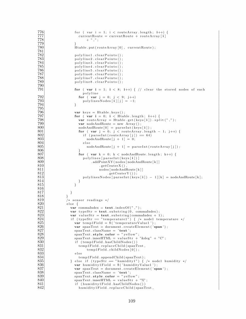
776 f o r ( var i = 1 ; i < routeArray . l ength ; i++) 777 currentRoute = currentRoute + routeArray [ i ]778 + ” , ” ;779 780 Htable . put ( routeArray [ 0 ] , currentRoute ) ;781782 po l y l i n e 1 . c l e a rPo i n t s ( ) ;783 po l y l i n e 2 . c l e a rPo i n t s ( ) ;784 po l y l i n e 3 . c l e a rPo i n t s ( ) ;785 po l y l i n e 4 . c l e a rPo i n t s ( ) ;786 po l y l i n e 5 . c l e a rPo i n t s ( ) ;787 po l y l i n e 6 . c l e a rPo i n t s ( ) ;788 po l y l i n e 7 . c l e a rPo i n t s ( ) ;789 po l y l i n e 8 . c l e a rPo i n t s ( ) ;790791 for ( var i = 1 ; i < 8 ; i++) // c l e a r the s to r ed nodes o f each
po l y l i n e792 for ( var j = 0 ; j < 9 ; j++)793 po ly l ine sNodes [ i ] [ j ] = −1;794 795796 var keys = Htable . keys ( ) ;797 for ( var i = 0 ; i < Htable . l ength ; i++) 798 var routeArray = Htable . get ( keys [ i ] ) . s p l i t ( ” , ” ) ;799 var nodeAndRoute = new Array ( ) ;800 nodeAndRoute [ 0 ] = par s e In t ( keys [ i ] ) ;801 for ( var j = 0 ; j < routeArray . l ength − 1 ; j++) 802 i f ( pa r s e In t ( routeArray [ j ] ) == 64)803 nodeAndRoute [ j + 1 ] = 0 ;804 e l s e805 nodeAndRoute [ j + 1 ] = par s e In t ( routeArray [ j ] ) ;806 807 for ( var k = 0 ; k < nodeAndRoute . l ength ; k++) 808 p o l y l i n e s [ pa r s e In t ( keys [ i ] ) ]809 . addPointXY( nodes [ nodeAndRoute [ k ] ]810 . getCenterX ( ) ,811 nodes [ nodeAndRoute [ k ] ]812 . getCenterY ( ) ) ;813 po ly l ine sNodes [ pa r s e In t ( keys [ i ] ) − 1 ] [ k ] = nodeAndRoute [ k ] ;814 815 816817 818 819 /∗ s enso r r ead ings ∗/820 e l s e 821 var commaIndex = text . indexOf ( ” , ” ) ;822 var typeStr = text . s ub s t r i ng (0 , commaIndex ) ;823 var va lueSt r = text . s ub s t r i ng ( commaIndex + 1) ;824 i f ( typeStr == ” temperature1 ” ) /∗ node1 temperature ∗/825 var temp1Field = $ ( ’ temperatureValue1 ’ ) ;826 var spanText = document . createElement ( ’ span ’ ) ;827 spanText . className = ’ text ’ ;828 spanText . style . color = ”ye l low ” ;829 spanText . innerHTML = va lueSt r + ”°” + ”C” ;830 i f ( temp1Field . hasChildNodes ( ) )831 temp1Field . r ep l a c eCh i ld ( spanText ,832 temp1Field . chi ldNodes [ 0 ] ) ;833 e l s e834 temp1Field . appendChild ( spanText ) ;835 e l s e i f ( typeStr == ”humidity1” ) /∗ node1 humidity ∗/836 var humidity1Fie ld = $ ( ’ humidityValue1 ’ ) ;837 var spanText = document . createElement ( ’ span ’ ) ;838 spanText . className = ’ text ’ ;839 spanText . style . color = ”ye l low ” ;840 spanText . innerHTML = va lueSt r + ”%” ;841 i f ( humidity1Fie ld . hasChildNodes ( ) )842 humidity1Fie ld . r ep l a c eCh i ld ( spanText ,
109

843 humidity1Fie ld . chi ldNodes [ 0 ] ) ;844 e l s e845 humidity1Fie ld . appendChild ( spanText ) ;846 e l s e i f ( typeStr == ” vo l tage1 ” ) /∗ node1 vo l tage ∗/847 var vo l t ag e1F i e l d = $ ( ’ voltageValue1 ’ ) ;848 var spanText = document . createElement ( ’ span ’ ) ;849 spanText . className = ’ text ’ ;850 spanText . style . color = ”ye l low ” ;851 spanText . innerHTML = va lueSt r + ”V” ;852 i f ( vo l t ag e1F i e l d . hasChildNodes ( ) )853 vo l t ag e1F i e l d . r ep l a c eCh i ld ( spanText ,854 vo l t ag e1F i e l d . chi ldNodes [ 0 ] ) ;855 e l s e856 vo l t ag e1F i e l d . appendChild ( spanText ) ;857 e l s e i f ( typeStr == ” l i g h t 1 ” ) /∗ node1 vo l tage ∗/858 var l i g h t 1F i e l d = $ ( ’ l i ghtValue1 ’ ) ;859 var spanText = document . createElement ( ’ span ’ ) ;860 spanText . className = ’ text ’ ;861 spanText . style . color = ”ye l low ” ;862 spanText . innerHTML = va lueSt r + ” lux ” ;863 i f ( l i g h t 1F i e l d . hasChildNodes ( ) )864 l i g h t 1F i e l d . r ep l a c eCh i ld ( spanText ,865 l i g h t 1F i e l d . chi ldNodes [ 0 ] ) ;866 e l s e867 l i g h t 1F i e l d . appendChild ( spanText ) ;868 e l s e i f ( typeStr == ” temperature8 ” ) /∗ node8 temperature ∗/869 var temp8Field = $ ( ’ temperatureValue8 ’ ) ;870 var spanText = document . createElement ( ’ span ’ ) ;871 spanText . className = ’ text ’ ;872 spanText . style . color = ”ye l low ” ;873 spanText . innerHTML = va lueSt r + ”°” + ”C” ;874 i f ( temp8Field . hasChildNodes ( ) )875 temp8Field . r ep l a c eCh i ld ( spanText ,876 temp8Field . chi ldNodes [ 0 ] ) ;877 e l s e878 temp8Field . appendChild ( spanText ) ;879 e l s e i f ( typeStr == ”humidity8” ) /∗ node8 humidity ∗/880 var humidity8Fie ld = $ ( ’ humidityValue8 ’ ) ;881 var spanText = document . createElement ( ’ span ’ ) ;882 spanText . className = ’ text ’ ;883 spanText . style . color = ”ye l low ” ;884 spanText . innerHTML = va lueSt r + ”%” ;885 i f ( humidity8Fie ld . hasChildNodes ( ) )886 humidity8Fie ld . r ep l a c eCh i ld ( spanText ,887 humidity8Fie ld . chi ldNodes [ 0 ] ) ;888 e l s e889 humidity8Fie ld . appendChild ( spanText ) ;890 e l s e i f ( typeStr == ” l i g h t 8 ” ) /∗ node1 vo l tage ∗/891 var l i g h t 8F i e l d = $ ( ’ l i ghtValue8 ’ ) ;892 var spanText = document . createElement ( ’ span ’ ) ;893 spanText . className = ’ text ’ ;894 spanText . style . color = ”ye l low ” ;895 spanText . innerHTML = va lueSt r + ” lux ” ;896 i f ( l i g h t 8F i e l d . hasChildNodes ( ) )897 l i g h t 8F i e l d . r ep l a c eCh i ld ( spanText ,898 l i g h t 8F i e l d . chi ldNodes [ 0 ] ) ;899 e l s e900 l i g h t 8F i e l d . appendChild ( spanText ) ;901 e l s e i f ( typeStr == ” vo l tage8 ” ) /∗ node8 vo l tage ∗/902 var vo l t ag e8F i e l d = $ ( ’ voltageValue8 ’ ) ;903 var spanText = document . createElement ( ’ span ’ ) ;904 spanText . className = ’ text ’ ;905 spanText . style . color = ”ye l low ” ;906 spanText . innerHTML = va lueSt r + ”V” ;907 i f ( vo l t ag e8F i e l d . hasChildNodes ( ) )908 vo l t ag e8F i e l d . r ep l a c eCh i ld ( spanText ,909 vo l t ag e8F i e l d . chi ldNodes [ 0 ] ) ;910 e l s e
110

911 vo l t ag e8F i e l d . appendChild ( spanText ) ;912 913 914 915 ,916917 on c l o s e : f unc t i on (m) 918 t h i s . ws = nu l l ;919 $ ( ’ t ex tF i e ld ’ ) . innerHTML = ’ ’ ;920 ,921922 one r r o r : f unc t i on ( e ) 923 a l e r t ( e ) ;924 ,925926 send : func t i on ( message ) 927 i f ( t h i s . ws )928 t h i s . ws . send (message ) ;929 930 ;931932 /∗ method for g e t t i n g route in fo rmat ion ∗/933 room . j o i n ( ) ;934 </script>935936 <div id=” foo t e r−content ”>937 <div id=” foo t e r−bg” class=” conta ine r ”>938 <div id=”column1”>939 <h2>Contact</h2>940 <p>941 Weiqi Zhang : weiqqi1028@gmail . com<br>Bradford G. Nickerson : bgn@unb . ca<br>
Unive r s i ty o f New942 Brunswick <br> Faculty o f Computer Sc i ence <br>943 Freder ic ton , NB. <br> Canada , E3B 5A3944 </p>945 </div>946 <div id=”column2”>947 <h2>Acknowledgements</h2>948 <p>Unive r s i ty o f New Brunswick Faculty o f Computer Sc i ence f o r949 t h e i r support on t h i s r e s ea r ch .</p>950 </div>951 <div id=”column3”>952 <h2>Assoc iated Links</h2>953 <ul>954 < l i><a955 href=”http :// bu l l s e y e . xbow . com:81/ Products / p r oduc td e t a i l s . aspx ? s i d=252”>956 The Telosb senso r node</a></ l i>957 < l i><a958 href=”http :// t o o l s . i e t f . org /html/ dra f t−i e t f −hybi−thewebsocketprotoco l −17
”>959 The WebSocket Protoco l</a></ l i>960 < l i><a961 href=”http ://www. j s g l . org /doku . php? id=home”>962 JavaScr ipt Graphics Library (JSGL)</a></ l i>963 < l i><a href=”http :// d ive intohtml5 . i n f o / canvas . html”> HTML5964 Canvas Element</a></ l i>965 < l i><a href=”http :// tomcat . apache . org /”> Apache Tomcat966 Webserver</a></ l i>967 </ul>968 </div>969 </div>970 </div>971972 </body>973 </html>
111

Vita
Candidate’s full name: Weiqi Zhang
University attended:September 2010 - October 2013Faculty of Computer ScienceUniversity of New BrunswickFredericton, New Brunswick, Canada
September 2006 - June 2010Bachelor of EngineeringShool of Information and Communication EngineeringBeijing University of Post and TelecommunicationsBeijing, China
Technical Report:Weiqi Zhang and Bradford G. Nickerson, “Wireless Sensor Network CommunicationProtocols”, UNB Faculty of Computer Science, TR11-208, May 2011, Fredericton,N.B., Canada.
Poster:Weiqi Zhang and Bradford G. Nickerson, “Poster: 6LoWPAN for mobile wirelesssensor network communication”, 10th UNB Computer Science Research Exposition,April 12, 2013, Fredericton, N.B., Canada.
Publications:Conference Presentations: