explicit dynamic analysis of sheet metal forming processes
TRANSCRIPT

HAL Id: hal-02386217https://hal.archives-ouvertes.fr/hal-02386217
Submitted on 29 Nov 2019
HAL is a multi-disciplinary open accessarchive for the deposit and dissemination of sci-entific research documents, whether they are pub-lished or not. The documents may come fromteaching and research institutions in France orabroad, or from public or private research centers.
L’archive ouverte pluridisciplinaire HAL, estdestinée au dépôt et à la diffusion de documentsscientifiques de niveau recherche, publiés ou non,émanant des établissements d’enseignement et derecherche français ou étrangers, des laboratoirespublics ou privés.
Explicit dynamic analysis of sheet metal formingprocesses using linear prismatic and hexahedral
solid-shell elementsPeng Wang, Hocine Chalal, Farid Abed-Meraim
To cite this version:Peng Wang, Hocine Chalal, Farid Abed-Meraim. Explicit dynamic analysis of sheet metal form-ing processes using linear prismatic and hexahedral solid-shell elements. Engineering Computations,Emerald, 2017, 34 (5), pp.1413-1445. �10.1108/EC-04-2016-0150�. �hal-02386217�

1
Explicit dynamic analysis of sheet metal forming processes using linear prismatic and hexahedral solidshell elements
Abstract
Propose The purpose of this paper is to propose two linear solid shell finite elements, a six-
node prismatic element denoted SHB6-EXP and an eight-node hexahedral element denoted
SHB8PS-EXP, for the three-dimensional modeling of thin structures in the context of explicit
dynamic analysis.
Design/methodology/approach These two linear solidshell elements are formulated based on
a purely three-dimensional approach, with displacements as the only degrees of freedom. To
prevent various locking phenomena, a reduced-integration scheme is used along with the assumed-
strain method. The resulting formulations are computationally efficient, since only a single layer
of elements with an arbitrary number of through-thickness integration points is required to model
3D thin structures.
Findings Via the VUEL user-element subroutines, the performance of these elements is
assessed through a set of selective and representative dynamic elasto-plastic benchmark tests,
impact-type problems and deep drawing processes involving complex non-linear loading paths,
anisotropic plasticity and double-sided contact. The obtained numerical results demonstrate the
good performance of the SHB-EXP elements in the modeling of 3D thin structures, with only a
single element layer and few integration points in the thickness direction.
Originality/value The extension of the SHB-EXP solidshell formulations to large-strain
anisotropic plasticity enlarges their application range to a wide variety of dynamic elasto-plastic
problems and sheet metal forming simulations. All simulation results reveal that the numerical
strategy adopted in this paper can efficiently prevent the various locking phenomena that
commonly occur in the 3D modeling of thin structural problems.
Keywords: Finite element, Solidshell concept, Explicit dynamic analysis, Anisotropic elasto-
plasticity, Impact problems, Sheet metal forming

2
1. Introduction
The finite element (FE) simulation of sheet metal forming processes has become an indispensable
tool in the design and manufacturing of modern products in many industries. Such a simulation
tool greatly assists designers and engineers in predicting the final shape of products and
optimizing forming setups, by replacing a number of expensive and time-consuming experimental
tests. However, the accuracy and efficiency of the FE simulation should be guaranteed in order to
obtain reliable predictions. Traditionally, for the simulation of thin structures, conventional shell
elements are used or alternatively low-order solid elements, when three-dimensional effects need
to be accounted for. However, conventional shell elements show limitations in the simulation of a
number of sheet metal forming processes, while low-order solid elements suffer from various
locking phenomena. In this regard, much effort has been devoted in the literature to establish
accurate and efficient finite element formulations.
The membrane finite element (Sukhomlinov et al., 1992; Huh et al., 1994; Huh and Choi, 1999)
has been widely used, due to its computational efficiency in the simulation of bending as well as
stretching-dominated sheet metal forming problems. In order to obtain more accurate results,
particular attention has been paid in the literature to the development of shell elements for the
modeling of thin structures. For instance, Guo et al. (2002) proposed an efficient shell element
based on the discrete Kirchhoff assumption for the simulation of springback in sheet metal
forming processes, while Lu et al. (2006) developed their own degenerated shell element based on
Mindlin–Reissner’s theory. Compared to membrane elements, shell elements offer better accuracy
for modeling bending effects in thin structures. However, the formulation of classical shell
elements is typically based on the assumption of plane-stress conditions, which limits their
application in sheet metal forming simulation. Further, they cannot account for thickness
variations, since only the mid-plane of the sheet is modeled, which makes the double-sided contact
difficult to handle.
Concurrently, continuum solid elements allow more realistic modeling for a number of
structural problems thanks to their three-dimensional formulation, thus avoiding geometric (mid-
plane) or kinematics assumptions as well as constitutive (plane-stress) restrictions. However, in
the simulation of thin structures, the use of solid elements involves meshes with too many
elements, which is partly attributable to element aspect ratio limitations as well as locking effects

3
in low-order formulations. In addition, several layers of solid elements are required in the
thickness direction in order to accurately describe the various non-linear phenomena, which
considerably increases the computational cost of the simulations.
More recently, the concept of solidshell elements has emerged, which represents nowadays an
interesting alternative to conventional solid and shell elements, in particular for the simulation of
sheet metal forming processes. In fact, solidshell elements combine the advantages of both solid
and shell formulations. Their main key features, which make them very attractive, may be
summarized as follows: the use of fully three-dimensional constitutive laws, without plane-stress
restrictions; easy connection with conventional solid elements, since displacements are the only
degrees of freedom; direct calculation of thickness variations, as this is based on physical nodes;
automatic consideration of double-sided contact; ability to accurately model thin structures with
only a single element layer and few integration points in the thickness direction.
In the past few decades, various solidshell elements have been developed in the literature, on
the basis of different approaches (Cho et al., 1998; Hauptmann and Schweizerhof, 1998; Puso,
2000; Sze and Yao, 2000; Abed-Meraim and Combescure, 2002; Parente et al., 2006; Reese, 2007;
Cardoso et al., 2008; Abed-Meraim and Combescure, 2009; Schwarze and Reese, 2009; Li et al.,
2011; Trinh et al., 2011; Edem and Gosling, 2013; Flores, 2013; Pagani et al., 2014). Most of
these formulations have been established based on the assumed strain method (ASM), the
enhanced assumed strain (EAS) approach, or the assumed natural strain (ANS) concept. Recent
formulations also combine some of these techniques in order to further eliminate all kinds of
spurious mechanisms (e.g., rank deficiencies) and locking phenomena. The key idea on which
these approaches are based is to enrich the kinematics (through additional enhanced/assumed
strain fields), in the aim of eliminating various locking effects (membrane, shear, volumetric,
thickness …). The reduced-integration rule is sometimes additionally used to alleviate some
locking effects, but this may lead to rank deficiency, which requires the element formulation to be
stabilized against hourglass (zero-energy) modes.
In this paper, two linear solidshell element formulations are proposed for the explicit dynamic
analysis of structural problems and sheet metal forming processes. These explicit dynamic
solid shell versions are derived by extending their quasi-static counterparts, and consist of a six-
node prismatic element, denoted SHB6-EXP, and an eight-node hexahedral element, denoted

4
SHB8PS-EXP. Their formulation is based on a fully three-dimensional approach, in which the
nodal displacements are the only degrees of freedom, in conjunction with the reduced-integration
technique and the assumed-strain method to alleviate the locking problems. The SHB8PS-EXP
element is an extension, to the explicit dynamic framework, of the previously developed quasi-
static version (Abed-Meraim and Combescure, 2009). Note that an explicit dynamic version of
this element has been formulated earlier to deal with impact problems (Abed-Meraim and
Combescure, 2002); however, it was restricted to isotropic elasto-plastic constitutive models. In
addition, selective benchmark tests revealed that it suffers from several locking phenomena. The
motivation of the improved subsequent formulation (Abed-Meraim and Combescure, 2009),
although within a quasi-static framework, was to eliminate the above-mentioned locking problems
through enhanced assumed-strain fields and a new stabilization scheme for the control of
hourglass modes. It is this latter version that is extended in the current work to the explicit
dynamic analysis of thin structural problems, through its coupling with advanced anisotropic
behavior models. As to the SHB6-EXP element, its dynamic explicit formulation is obtained here,
for the first time, by extending the quasi-static version developed in Trinh et al. (2011). In the
latter contribution, various popular benchmark tests have been used to assess the performance of
this solid shell element in the framework of quasi-static small-strain analysis and linear elastic
problems. In the current work, the explicit dynamic extensions SHB8PS-EXP and SHB6-EXP,
which are provided with a simple lumped mass matrix, are formulated within the framework of
large-strain anisotropic plasticity and implemented into the explicit dynamic code ABAQUS for
the simulation of impact problems and complex and challenging sheet metal forming processes
that are difficult to perform using quasi-static solvers.
The remainder of the paper is organized as follows. The explicit dynamic formulation of the
SHB-EXP solidshell elements is first presented in Section 2. Then, the performance of the SHB-
EXP elements is evaluated in Section 3 through various benchmark tests, including selective and
representative dynamic/impact problems. To assess the performance of the SHB-EXP elements in
complex highly non-linear test problems, the proposed solid shell elements are applied in Section
4 to the simulation of three deep drawing processes, involving geometric non-linearities,
anisotropic elasto-plastic behavior, and double-sided contact. All of the numerical results obtained
with the SHB-EXP elements are compared, on the one hand, to those provided by state-of-the-art

5
elements available in ABAQUS, using equivalent mesh refinement, and, on the other hand, to
reference solutions and experimental results taken from the literature. Finally, the main
discussions and concluding remarks are summarized in Section 5.
2. Formulation of linear solid–shell elements
This section provides the formulation of the SHB8PS-EXP and SHB6-EXP solidshell elements
and the associated new enhancements in the context of explicit dynamic analysis. The interested
reader may refer to Abed-Meraim and Combescure (2009) and Trinh et al. (2011), respectively,
for their detailed implicit quasi-static formulations.
2.1 General formulation of the SHB6-EXP and SHB8PS-EXP elements
The reference geometry for the six-node prismatic solid shell element SHB6-EXP and for the
eight-node hexahedral solidshell element SHB8PS-EXP is shown in Figures 1(a) and (b),
respectively, where a special direction is chosen to represent the thickness direction. Along this
direction, a user-defined arbitrary number of integration points are arranged. This choice aims at
providing the proposed elements, although geometrically three-dimensional, with some shell
features. It also allows alleviating some locking phenomena and improving the computational
efficiency of the elements, by using only a single element layer in the simulation of thin structures.
(a) (b)
Figure 1. Geometry of the SHB-EXP elements and location of their integration points in the
reference coordinate frame: (a) SHB6-EXP element and (b) SHB8PS-EXP element
2.1.1 Linear interpolation of the elements. The current SHB-EXP solidshell elements are
isoparametric elements, and use the classical linear shape functions for continuum standard
hexahedral and prismatic elements. Based on this three-dimensional formulation, the coordinates

6
ix and velocities iv inside an element are interpolated using the linear shape functions IN , the
nodal coordinates iIx and the nodal velocities iIv as
1
( , , ) ( , , )n
i iI I I iII
x x N N x , (1)
),,(IiIi Nvv , (2)
where the lowercase subscript i varies from 1 to 3 and represents the spatial coordinate directions,
while the uppercase subscript I varies from 1 to n , where n denotes the number of element nodes
(i.e., 6n for the SHB6-EXP element, and 8n for the SHB8PS-EXP element). In what follows,
the convention of implied summation on repeated indices will be adopted, as in Eq. (2) above.
2.1.2 Derivation of discrete gradient operator. Combining Eqs. (1) and (2) allows us to derive
the complete expression of the velocity field iv as follows:
0 1 1 2 2 3 3 1 1i i i i i i iv a a x a x a x c h c h with 1,2,3i , (3)
where the functions h are specific to each of the SHB-EXP elements. For instance, subscript
varies from 1 to 4 for the SHB8PS-EXP element, while it varies from 1 to 2 for the SHB6-EXP
element. Functions h have the following expressions:
4321 hhhh ,,, . (4)
Applying, in particular, the velocity field expansion (3) to the element nodes, the nodal velocity
vectors id , associated with the hexahedral and prismatic SHB-EXP elements, can be expressed in
the following compact form:
hhxxxsd iiiiiii ccaaaa 113322110 with 1,2,3i , (5)
where ix , 1,2,3i , represent the nodal coordinate vectors, while the detailed expressions of
vectors s and h can be found in Trinh et al. (2011) for the six-node prismatic element, and in
Abed-Meraim and Combescure (2009) for the eight-node hexahedral element.
By introducing the derivatives of the shape functions ),,(, 000ii Nb , 1,2,3i , also known as
Hallquist’s vectors (Hallquist, 1983), and using some orthogonality relations that are easy to
demonstrate, the expression of the unknown constants in Eqs. (3) and (5) can be obtained (see, e.g.,
Abed-Meraim and Combescure, 2009; Trinh et al., 2011)

7
3
1
,
1where:
T Tji j i i i
Tj j
j
a c
k
b d d
h h x b, (6)
with 2k for the SHB6-EXP element, and 8k for the SHB8PS-EXP element. Substituting the
expressions of these constants into Eq. (3), the velocity field can be rewritten in the following
more convenient form:
iTTTTT
ii hhxxxav dbbb 113322110 . (7)
The velocity gradient is then obtained by differentiating the above expression with respect to
jx as follows:
iT
jTji
Tj
Tjji hhv dbdb ,,, . (8)
Finally, the vector form of the velocity gradient operator can be expressed as follows:
,
,
,
, ,
, ,
, ,
x x
y yx
z zs y
x y y xz
y z z y
x z z x
v
v
v
v v
v v
v v
d
v B d B d
d
, (9)
where the discrete gradient operator B takes the following matrix form:
Tx
Tx
Tz
Tz
Ty
Ty
Tz
Tz
Tx
Tx
Ty
Ty
Tz
Tz
Ty
Ty
Tx
Tx
hh
hh
hh
h
h
h
bb
bb
bb
b
b
b
B
,,
,,
,,
,
,
,
0
0
0
00
00
00
. (10)
2.1.3 Hu Washizu principle and internal forces. The assumed-strain method used in the
formulation of the SHB-EXP solid–shell elements is based on the simplified form of the
Hu Washizu mixed variational principle, as proposed by Simo and Hughes (1986)
( ) 0e
T T extd d f , (11)

8
where represents a variation, the assumed-strain rate, the stress state obtained by the
constitutive law, d the nodal velocities, and extf the external nodal forces. Such a simplified
principle is very convenient, because it only involves the interpolation of the velocity and of the
assumed-strain field. The latter may be expressed over the element using an appropriate projection,
which will be denoted B , of the original discrete gradient operator B
,x t x tB d . (12)
By substituting Eq. (12) into the simplified expression (11) of the HuWashizu mixed
variational principle, the following equation is obtained:
0e
T T extdd B f . (13)
Because d can be chosen arbitrarily, the above equation allows the expression of the internal
force vector to be derived as follows:
int
e
T df B . (14)
In addition, due to the particular location along the same line of the integration points, it has
been shown in Abed-Meraim and Combescure (2009) that the above formulation of the eight-node
hexahedral solidshell element generates six hourglass modes. These spurious zero-energy modes
are controlled by applying an efficient stabilization technique, following the assumed-strain
approach proposed in Belytschko and Bindeman (1993). The resulting internal force vector is
obtained by adding to the usual internal forces (see Eq. (14)) a stabilization term, as follows:
int STAB
e
T df B f . (15)
More details on the derivation of the expression of the stabilization forces STABf in the case of
the eight-node hexahedral solidshell element can be found in Abed-Meraim and Combescure
(2002). It is worth noting that the formulation of the six-node prismatic solidshell element does
not induce hourglass modes and, therefore, no additional stabilization terms are needed for the
calculation of the associated internal forces. However, an appropriate projection of the strains for
the SHB6-EXP element is required to eliminate some locking phenomena (Trinh et al., 2011).
2.1.4 Constitutive equations. The formulation of the SHB-EXP solidshell elements requires
resorting to several local frames in order to perform the entire calculations (see Figure 2 for
illustration). These local physical or material coordinate systems are motivated by the computation

9
of the elasticity law, the material plastic anisotropy, or the stabilization terms. For instance, the so-
called “element frame” is introduced for the definition of the material elastic properties.
Accordingly, the elasticity law is specified in such a local physical coordinate system, which
corresponds to the element mid-plane associated with the -coordinate of each integration point.
In these local coordinate systems, which are attached to the integration points of the element, the
classical three-dimensional elasticity matrix is modified so that plane-stress conditions are
approached. This modification in the elasticity matrix, which has been validated in the earlier
quasi-static formulations of the SHB elements (see, e.g., Abed-Meraim and Combescure, 2009;
Trinh et al., 2011), allows enhancing the performance of the proposed elements with regard to
thickness locking. Such a specific improved plane-stress type elasticity matrix eleC is defined as
follows:
ele2
2 0 0 0 0
2 0 0 0 0
0 0 0 0 0with and
2 1 10 0 0 0 0
0 0 0 0 0
0 0 0 0 0
E E EC , (16)
where E and are Young’s modulus and Poisson’s ratio, respectively.
The so-called “material frame” is another local physical coordinate system, which is introduced
to account for the initial plastic anisotropy of the material and its evolution in the course of
deformation. The time integration of the large-strain anisotropic elasto-plastic constitutive
equations, which is achieved at each integration point, also uses this local material frame in order
to satisfy the objectivity (material invariance) requirements.
Finally, a third local coordinate system, designated as “co-rotational frame”, is defined at the
element level in order to simplify the calculation of the stabilization terms involved in the
expression of the internal forces, in the particular case of SHB8PS-EXP element.
For a given rotation matrix R , corresponding to one of the three local coordinate systems
described above, the tensor variables can be transformed from the global coordinate system into
the local coordinate frame by using the following classical formulas:
loc T glo
loc T T glo
a R a R
A R R A R R, (17)

10
where loca and locA represent second-order, respectively, fourth-order tensors expressed in the
local coordinate system, while gloa and gloA are their expressions in the global coordinate frame.
Using the indicial notation, the above equation can be rewritten in the following equivalent form:
loc glo
loc glo
ij pi qj pq
ijkl pi qj rk sl pqrs
a R R a
A R R R R A, (18)
where the lowercase subscripts , , , , , ,i j k l p q r and s vary from 1 to 3.
z
y
x global frame
integration points
thickness direction
Figure 2. Illustration of the local coordinate systems, and the associated rotation matrices, used in
the formulation of SHB-EXP solidshell elements
As stated before, in the formulation of the SHB-EXP solid shell elements, the rate constitutive
equations are integrated in the local material frame in order to ensure material objectivity within
the large-strain framework. All constitutive equations are implemented into the finite element
software package ABAQUS/Explicit, within the framework of large plastic deformations, using an
independent VUMAT-like user-material subroutine. The latter is called by the user-element
subroutines associated with the SHB-EXP elements to update the stress state and other internal
variables, which allows easy and modular coupling with any new constitutive model,
independently of the element formulation. In what follows, the constitutive equations are

11
presented in the local material frame described above. In this material frame, the rate form of the
Cauchy stressstrain relationship is expressed using the hypoelastic law defined by
: pC D D , (19)
where C is the fourth-order elasticity tensor, which is obtained by rotating the elasticity tensor
eleC (see Eq. (16)) from the element frame to the material frame. The strain rate tensor D is
additively decomposed into an elastic part eD and a plastic part pD . The latter is defined by an
associative plastic flow rule
p fD V , (20)
where f represents the plastic yield surface, and V is the flow direction normal to the yield
surface. The plastic multiplier in Eq. (20) is determined by the consistency condition.
In this work, the anisotropic plastic behavior of the material is taken into account by
considering Hill’s quadratic anisotropic yield criterion (Hill, 1948). The corresponding plastic
yield function f is written in the following form:
0eqf Y , (21)
where : :eq H is the equivalent stress, and is the deviatoric part of the
Cauchy stress tensor. The fourth-order tensor H contains the six anisotropy coefficients of Hill’48
quadratic yield criterion. The isotropic hardening of the material is described by the scalar variable
Y , which characterizes the size of the yield surface, while kinematic hardening is represented by
the back-stress tensor .
For the above-described constitutive equations, it can be shown that the set of internal variables
is governed by a generic differential equation of the form
xx U x , (22)
where vector x contains all variables of the model that need to be updated. The function xU x
depends on the specific equations that govern the evolution of internal variables, which can be
either scalar or tensorial according to the type of variables. This general form (22) allows
encompassing various hardening descriptions as well as more advanced yield surface models. For
instance, the UY functions corresponding to the evolution of isotropic hardening, for the three

12
different hardening models considered in this work, are summarized in Table 1. In this table, 0
and are the initial yield stress and equivalent plastic strain, respectively, while K , 0 , and N
represent hardening parameters.
Table 1. Definition of the isotropic hardening models considered and their evolution laws.
Using the above constitutive equations and the consistency condition 0f , the expression of
the plastic multiplier is derived as follows:
: :
: : : UY
V C DV C V V U
. (23)
2.1.5 The basic expression of the mass matrix. In this work, the SHB-EXP elements are
implemented into the finite element software package ABAQUS/Explicit, within the framework of
explicit dynamic analysis. For this purpose, the mass matrix needs to be defined at the very
beginning of the calculations using the SHB-EXP elements, while the stiffness matrix is not
required in the element formulation. Several methods are available in the literature to compute the
mass matrix (see, e.g., Zienkiewicz, 2006). Here, a diagonal lumped element mass matrix eM is
adopted for all SHB-EXP elements. This element mass matrix has a size of 3 3n n , with n being
the number of nodes in the element, and it is constructed from the following bloc of components:
M0
eI J
IJ
m N N d I J
I J, with
1e e
n
I II
m d N N d (24)
where IN and JN are the shape functions, and is the material mass density.
3. Numerical benchmark tests
In this section, a representative set of dynamic benchmark tests involving geometric and material
non-linearities is selected to assess the performance of the SHB-EXP solid–shell elements. It is
worth noting that the converged solutions for these benchmark tests are achieved using only a
single element layer with two integration points through the thickness.

13
For comparison purposes, all numerical results obtained with the SHB-EXP elements are
compared with those given by ABAQUS elements (using similar meshes with the same number of
elements in each spatial direction) as well as with reference solutions taken from the literature.
The list of SHB-EXP elements with their counterparts from ABAQUS (prismatic and hexahedral
elements as well as shell elements) are summarized in Table 2.
Table 2. Prismatic, hexahedral as well as shell finite elements used in the simulations.
In all simulations that follow, the meshes made of hexahedral elements adopt the nomenclature
N1×N2×N3, where N1 indicates the number of elements in the length direction, N2 the number of
elements in the width direction, and N3 the number of elements in the thickness direction. For
meshes made of prismatic elements, the total number of elements is twice that obtained by using
hexahedral elements, due to the in-plane sub-division of a quadrangle into two triangles, resulting
in the following nomenclature (N1×N2×2)×N3. For ABAQUS shell elements, the nomenclature
used for triangular shell elements is N1×N2×2, while the nomenclature for quadrilateral shell
elements is simply N1×N2. It is worth noting that the solid elements C3D6 and C3D8R in the
explicit dynamic code ABAQUS are provided with a single integration point. Therefore, in what
follows, several element layers are required for the C3D6 and C3D8R elements in order to have
the same number of integration points in the thickness direction as the other elements used for
comparison.
3.1 Cantilever beam bending with a concentrated force
The elastic cantilever beam bending problem studied by Olovsson et al. (2004) is considered
here. The geometric dimensions, material elastic properties, applied loading, and boundary
conditions are all specified in Figure 3. For triangular shell or prismatic elements, the meshes
include 40 elements uniformly distributed along the length and one element in the width, while for
quadrilateral shell or hexahedral elements, the beam is discretized with 10 elements along the
length and one element in the width. Figure 4 compares the deflection history at one corner of the
free end of the beam obtained with the SHB-EXP elements and ABAQUS elements with the

14
reference solution taken from Olovsson et al. (2004). The numerical results show that the mesh
used for the C3D6 and C3D8R ABAQUS elements is not sufficient to obtain accurate solutions,
due to the poor behavior of these solid elements with regard to locking and hourglassing, while the
SHB-EXP elements, as well as the S3R, SC6R, S4R, and SC8R ABAQUS elements are in good
agreement with the reference solution. Although requiring twice more elements (i.e., two element
layers in the thickness direction), the results given by conventional ABAQUS solid elements are
still clearly affected by locking phenomena that are involved in this typical bending-dominated
problem, which is not the case of the SHB-EXP elements, thanks to the implementation of the
assumed-strain method in their formulation.
F=100 N
t=0.01 m
E=100 GPav=0=1000 kg/m3
Figure 3. Elastic cantilever beam subjected to a concentrated force
(a)
0.00 0.01 0.02 0.03 0.04 0.05 0.06 0.07 0.08 0.09 0.100.00
0.02
0.04
0.06
0.08
0.10
0.12 S3R 40×1×2 SC6R (40×1×2)×1 C3D6 (40×1×2)×2
Olovsson et al. (2004) SHB6-EXP (40×1×2)×1
Ver
tical
def
lect
ion
at f
ree
ext
rem
ity (
m)
Time (s)
(b)
0.00 0.01 0.02 0.03 0.04 0.05 0.06 0.07 0.08 0.090.100.00
0.02
0.04
0.06
0.08
0.10
0.12 S4R 10×1 SC8R 10×1×1 C3D8R 10×1×2
Olovsson et al. (2004) SHB8PS-EXP 10×1×1
Ve
rtic
al d
efle
ctio
n at
free
ext
rem
ity (
m)
Time (s)
Figure 4. Tip deflection history for the cantilever beam subjected to a concentrated load: using (a)
triangular shell / prismatic elements, and (b) using quadrilateral shell / hexahedral elements

15
3.2 Cantilever beam bending with a uniform pressure
In this subsection, an elastic cantilever beam subjected to a uniform pressure, as proposed by
Belytschko et al. (1984), is investigated to assess the bending behavior of the proposed SHB-EXP
elements. The geometric dimensions, material elastic properties, applied loading, and boundary
conditions are all defined in Figure 5. Finite element simulations have been performed using both
the SHB-EXP elements and ABAQUS elements, and the corresponding solutions, in terms of
deflection history at one corner of the beam free end (see point A in Figure 5), are compared with
the reference solution given in Belytschko et al. (1984). The cantilever beam is discretized with 20
elements uniformly distributed along the length and one element in the width for triangular shell
or prismatic elements, and 5 elements along the length and one element in the width for
quadrilateral shell or hexahedral elements. Figure 6 depicts all of the numerical results obtained
with the SHB-EXP elements and ABAQUS elements. Similar to the previous test, the C3D6 and
C3D8R ABAQUS elements require finer meshes to correctly model this cantilever beam bending
benchmark problem. Indeed, although necessitating twice more elements (two element layers in
the thickness direction), the results displayed by the C3D6 and C3D8R ABAQUS elements still
show clear differences with the reference solution, due to their sensitivity to locking effects. By
contrast, the results obtained with the proposed SHB-EXP elements show excellent agreement
with the reference solution as well as with the S3R, SC6R, S4R, and SC8R ABAQUS elements. It
is also revealed, through this bending benchmark test, that the SHB-EXP elements are more
suitable to model relatively thick structures than their ABAQUS solid counterparts.
t=1 in.
yx
z
A
p=2.85 psi
E=12000 psiv=0.2=1.024 10-6 Ib-sec2/in4
Figure 5. Elastic cantilever beam subjected to a uniform pressure

16
(a)
0.000 0.001 0.002 0.003 0.004 0.005 0.006-2
0
2
4
6
8
Belytschko et al. (1984) SHB6-EXP (20×1×2)×1 S3R 20×1×2 SC6R (20×1×2)×1 C3D6 (20×1×2)×2z-
De
flect
ion
at f
ree
extr
emity
(in
)
Time (s)
(b)
0.000 0.001 0.002 0.003 0.004 0.005 0.006-2
0
2
4
6
8
Belytschko et al. (1984) SHB8PS-EXP 5×1×1 S4R 5×1 SC8R 5×1×1 C3D8R 5×1×2z-
Def
lect
ion
at fr
ee e
xtre
mity
(in
)
Time (s)
Figure 6. Tip deflection history for the cantilever beam subjected to a uniform pressure: using (a)
triangular shell / prismatic elements, and (b) using quadrilateral shell / hexahedral elements
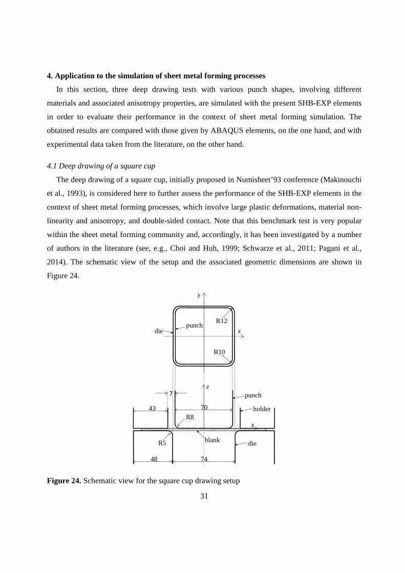
3.3 In-plane bending of a twisted beam
The in-plane bending of a twisted beam, as proposed by Belytschko et al. (1992), is a more
severe benchmark test than the two previous ones, since it involves both in-plane bending and
torsion of the beam. As illustrated in Figure 7, the twisted beam is bent at its free end along the in-
plane direction. The geometry, material elastic properties and boundary conditions are all
specified in Figure 7. Figure 8 compares the deflection history in the load direction at one corner
of the free end of the beam, as obtained with the SHB-EXP elements and ABAQUS elements,
with the reference solution taken from Belytschko et al. (1992). It can be seen that the SHB-EXP
elements perform very well with respect to the reference solution, for this in-plane bending
problem, which is also the case for the ABAQUS prismatic solid shell element SC6R and
ABAQUS shell elements. However, as pointed out in the two previous benchmark tests, a finer
mesh is required for the ABAQUS solid elements C3D6 and C3D8R, in order to obtain an
accurate solution, which is also the case here for the ABAQUS hexahedral solidshell element
SC8R.
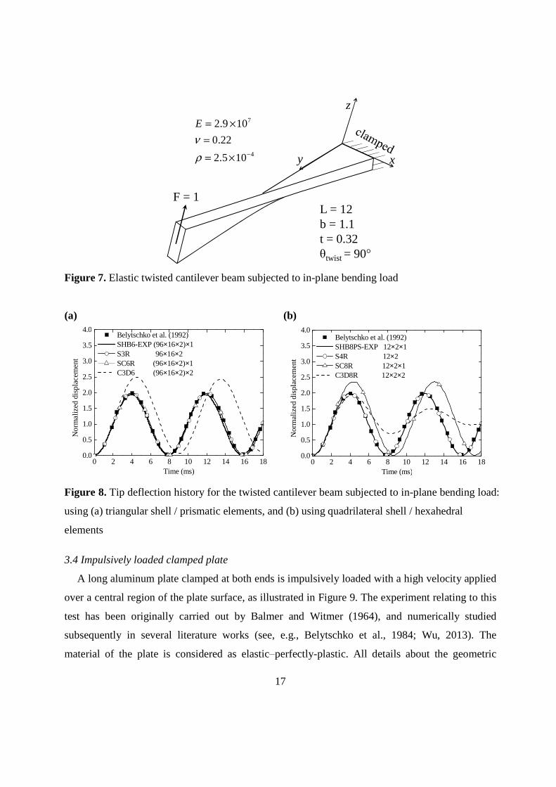
17
x
z
y
F = 1L = 12b = 1.1t = 0.32
twist = 90
4
7
1052
220
1092
.
.
.E
Figure 7. Elastic twisted cantilever beam subjected to in-plane bending load
(a)
0 2 4 6 8 10 12 14 16 180.0
0.5
1.0
1.5
2.0
2.5
3.0
3.5
4.0
Nor
ma
lized
dis
plac
emen
t
Time (ms)
Belytschko et al. (1992) SHB6-EXP (96×16×2)×1 S3R 96×16×2 SC6R (96×16×2)×1 C3D6 (96×16×2)×2
(b)
0 2 4 6 8 10 12 14 16 180.0
0.5
1.0
1.5
2.0
2.5
3.0
3.5
4.0
Nor
mal
ize
d di
spla
cem
ent
Time (ms)
Belytschko et al. (1992) SHB8PS-EXP 12×2×1 S4R 12×2 SC8R 12×2×1 C3D8R 12×2×2
Figure 8. Tip deflection history for the twisted cantilever beam subjected to in-plane bending load:
using (a) triangular shell / prismatic elements, and (b) using quadrilateral shell / hexahedral
elements
3.4 Impulsively loaded clamped plate
A long aluminum plate clamped at both ends is impulsively loaded with a high velocity applied
over a central region of the plate surface, as illustrated in Figure 9. The experiment relating to this
test has been originally carried out by Balmer and Witmer (1964), and numerically studied
subsequently in several literature works (see, e.g., Belytschko et al., 1984; Wu, 2013). The
material of the plate is considered as elasticperfectly-plastic. All details about the geometric

18
dimensions, prescribed loading, and elasto-plastic material parameters are summarized in Figure 9.
Owing to the symmetry of the problem, one half of the plate is modeled using the proposed SHB-
EXP elements as well as ABAQUS elements, for comparison purposes.
yz
x
Initial velocity=5200 in/s
2 in
10 in
0.125 in
E=1.04 107 psiv=0.3
0=4.14 104 psi=2.61 10-4 Ib-sec2/in4
Figure 9. Description of the elasticplastic clamped plate explosively loaded with an initial
velocity.
Figure 10 shows the predictions in terms of the vertical displacement history at the central point
of the plate, along with the experimental result taken from Balmer and Witmer (1964) and the
numerical reference solution obtained by Wu (2013). Compared with the simulation results given
by ABAQUS elements, the results obtained with the SHB-EXP elements are the closest to the
experimental results. This demonstrates the good capabilities of the proposed solidshell elements
in handling elasticplastic problems with large displacements under highly non-linear dynamic
loading conditions.

19
(a)
0.0 0.2 0.4 0.6 0.8 1.0 1.2 1.4 1.60.0
0.1
0.2
0.3
0.4
0.5
0.6
0.7
0.8
0.9
Dis
plac
emen
t (in
)
Time (×10-3s)
Experiment (Balmer andWitmer,1964) Wu (2013) SHB6-EXP (20×4×2)×1 S3R 20×4×2 SC6R (20×4×2)×1 C3D6 (20×4×2)×2
(b)
0.0 0.2 0.4 0.6 0.8 1.0 1.2 1.4 1.60.0
0.1
0.2
0.3
0.4
0.5
0.6
0.7
0.8
0.9
Dis
plac
emen
t (in
)
Time (×10-3s)
Experiment (Balmer and Witmer, 1964) Wu (2013) SHB8PS-EXP 20×4×1 S4R 20×4 SC8R 20×4×1 C3D8R 20×4×2
Figure 10. Displacement history at the central point of the elastic plastic clamped plate: using (a)
triangular shell / prismatic elements, and (b) using quadrilateral shell / hexahedral elements
3.5 Low velocity impact of a circular plate
The dynamic response of a clamped circular plate subjected to impact by a projectile is
investigated here to assess the capabilities of the proposed SHB-EXP elements in dealing with
elastic plastic impactcontact problems. Note that this dynamic benchmark test has previously
been studied by Chen et al. (2007) and Mars et al. (2015). The geometric dimensions for the plate
and the projectile as well as the prescribed loading and boundary conditions are all defined in
Figure 11. The material of the circular plate is made of 6061-T6 aluminum alloy with the
following elastic plastic properties: Young’s modulus 69 GPaE , Poisson’s ratio , initial
yield stress 290 MPa, and mass density 32600 kg / m . The projectile is modeled as a
rigid body with an assigned mass at its reference point. The contact between the circular plate and
the projectile is assumed to be frictionless, using the hard contact approach available in the
ABAQUS/Explicit code. Two typical cases, with different initial weight and velocity for the
projectile, are considered:
Case 1: M = 23.5 g, V0 = 49.1 m/s.
Case 2: M = 54.4 g, V0 = 29.9 m/s.

20
Figure 11. Schematic representation of a circular plate subjected to impact by a projectile
Considering the symmetry of the problem, only one quarter of the plate is modeled using an in-
plane discretization of 2708 elements in the case of prismatic elements, 2722 elements in the case
of triangular shell elements, 934 elements in the case of hexahedral elements, and 951 elements in
the case of quadrilateral shell elements (see Figure 12 for illustration). Similar to the previous test,
all simulations are carried out using two integration points in the thickness direction, which means
two element layers in the case of the ABAQUS C3D8R and C3D6 solid elements, and only a
single element layer for all other elements used for comparison. The history of velocity and impact
force for the projectile as well as the displacement response at the center of the plate are analyzed
using the proposed SHB-EXP elements, which are then compared both with ABAQUS elements
and with reference solutions given in Chen et al. (2007). In addition to these numerical
comparisons, all of the simulation results are qualitatively compared with the experiments
performed by Chen et al. (2007).
(a) (b)
Figure 12. Initial in-plane mesh for the clamped circular plate under impact by a projectile: using
(a) triangular shell / prismatic elements, and (b) using quadrilateral shell / hexahedral elements

21
Figure 13 shows the experimental results in terms of history of velocity and impact force for
the projectile for both studied cases, as reported in Chen et al. (2007). These experimental data
help understand the main stages that characterize such impact processes. The first stage
corresponds to the elasticplastic indentation of the circular plate, and lasts until a peak in the
impact force response appears. Then, the recovery stage for the circular plate starts, which is
characterized by a gradual reduction in the contact between the projectile and the circular plate,
until the impact force vanishes. The final stage corresponds to the complete separation between
the projectile and the circular plate, which is indicated by a zero impact force and a constant
velocity for the projectile.
(a) (b)
Figure 13. Experimental results in terms of history of velocity and impact force for the projectile
for both studied cases: (a) case 1, and (2) case 2
The velocity and the impact force obtained with the SHB-EXP solidshell elements, for both
cases 1 and 2, are compared in Figures 1419 with the results given by ABAQUS elements as well
as with the numerical reference solutions given in Chen et al. (2007). For more clarity in these
cross comparisons, the results given by the SHB-EXP elements are compared in Figures 14 and 15
with those yielded by ABAQUS shell elements, in Figures 16 and 17 with ABAQUS solidshell
elements, and in Figures 18 and 19 with ABAQUS solid elements. It can be seen that the double
impact force peak, which is typically observed in experiments (see Figures 13(a)–(b)), is well
reproduced by the SHB-EXP elements for both studied cases. More specifically, the maximum
impact force peak, corresponding to the end of the indentation stage, is reached for the SHB-EXP
elements when the velocity of the projectile decreases to zero, which is consistent with the
-0.1 0.0 0.1 0.2 0.3 0.4 0.5 0.6 0.7-20
-10
0
10
20
30
40
50
Vel
ocity
(m
/s)
Time (ms)
Velocity
0
1
2
3
4
5
6
7
Force
For
ce (
kN)
Case 1: M=23.5g, V0=49.1m/s(a) Experiment
-0.1 0.0 0.1 0.2 0.3 0.4 0.5 0.6 0.7 0.8 0.9-20
-10
0
10
20
30V
eloc
ity (
m/s
)
Time (ms)
Velocity
0
1
2
3
4
5
6
7
Force
For
ce (
kN)
Case 2: M=54.4g, V0=29.9m/s(b) Experiment

22
numerical reference solutions given by Chen et al. (2007) and the experimental observations in
both studied cases.
In terms of comparison with ABAQUS, the results obtained with the SHB-EXP elements show
good agreement with both solid and solidshell ABAQUS elements (see Figures 1619), while
ABAQUS shell elements provide the farthest results with respect to the reference solution. It
should be recalled once again that a finer mesh is required for the ABAQUS solid elements, with
two element layers in the thickness direction, which involves twice more elements than their
solid shell counterparts.
0.0 0.2 0.4 0.6 0.8 1.0
-30
-20
-10
0
10
20
30
40
50
60
Vel
ocity
(m
/s)
Time (ms)
Velocity (Chen et al., 2007) Velocity (SHB6-EXP) Velocity (S3R)
Case 1: M=23.5g, V0=49.1m/s
0.0 0.2 0.4 0.6 0.8 1.0
0
1
2
3
4
5
6
7
8
For
ce (
kN)
Time (ms)
Case 1: M=23.5g, V0=49.1m/s
Force (Chen et al., 2007) Force (SHB6-EXP) Force (S3R)
0.0 0.2 0.4 0.6 0.8 1.0
-30
-20
-10
0
10
20
30
40
50
60
Ve
loci
ty (
m/s
)
Time (ms)
Velocity (Chen et al., 2007) Velocity (SHB8PS-EXP) Velocity (S4R)
Case 1: M=23.5g, V0=49.1m/s
0.0 0.2 0.4 0.6 0.8 1.0
0
1
2
3
4
5
6
7
8
For
ce (
kN)
Time (ms)
Case 1: M=23.5g, V0=49.1m/s
Force (Chen et al., 2007) Force (SHB8PS-EXP) Force (S4R)
Figure 14. History of velocity (left) and impact force (right) for the projectile, obtained with the
SHB-EXP and ABAQUS shell elements along with the reference solutions for case 1

23
0.0 0.2 0.4 0.6 0.8 1.0
-10
0
10
20
30
40
Vel
ocity
(m
/s)
Time (ms)
Velocity (Chen et al., 2007) Velocity (SHB6-EXP) Velocity (S3R)
Case 2: M=54.4g, V0=29.9m/s
0.0 0.2 0.4 0.6 0.8 1.0
0
1
2
3
4
5
Fo
rce
(kN
)
Time (ms)
Case 2: M=54.4g, V0=29.9m/s
Force (Chen et al., 2007) Force (SHB6-EXP) Force (S3R)
0.0 0.2 0.4 0.6 0.8 1.0
-10
0
10
20
30
40
Vel
oci
ty (
m/s
)
Time (ms)
Velocity (Chen et al., 2007) Velocity (SHB8PS-EXP) Velocity (S4R)
Case 2: M=54.4g, V0=29.9m/s
0.0 0.2 0.4 0.6 0.8 1.0
0
1
2
3
4
5F
orc
e (
kN)
Time (ms)
Case 2: M=54.4g, V0=29.9m/s
Force (Chen et al., 2007) Force (SHB8PS-EXP) Force (S4R)
Figure 15. History of velocity (left) and impact force (right) for the projectile, obtained with the
SHB-EXP and ABAQUS shell elements along with the reference solutions for case 2

24
0.0 0.2 0.4 0.6 0.8 1.0
-30
-20
-10
0
10
20
30
40
50
60
Vel
ocity
(m
/s)
Time (ms)
Velocity (Chen et al., 2007) Velocity (SHB6-EXP) Velocity (SC6R)
Case 1: M=23.5g, V0=49.1m/s
0.0 0.2 0.4 0.6 0.8 1.0
0
1
2
3
4
5
6
7
8
For
ce (
kN)
Time (ms)
Case 1: M=23.5g, V0=49.1m/s
Force (Chen et al., 2007) Force (SHB6-EXP) Force (SC6R)
0.0 0.2 0.4 0.6 0.8 1.0
-30
-20
-10
0
10
20
30
40
50
60
Vel
ocity
(m
/s)
Time (ms)
Velocity (Chen et al., 2007) Velocity (SHB8PS-EXP) Velocity (SC8R)
Case 1: M=23.5g, V0=49.1m/s
0.0 0.2 0.4 0.6 0.8 1.0
0
1
2
3
4
5
6
7
8
For
ce (
kN)
Time (ms)
Case 1: M=23.5g, V0=49.1m/s Force (Chen et al., 2007) Force (SHB8PS-EXP) Force (SC8R)
Figure 16. History of velocity (left) and impact force (right) for the projectile, obtained with the
SHB-EXP and ABAQUS solidshell elements along with the reference solutions for case 1

25
0.0 0.2 0.4 0.6 0.8 1.0
-10
0
10
20
30
40
Vel
oci
ty (
m/s
)
Time (ms)
Velocity (Chen et al., 2007) Velocity (SHB6-EXP) Velocity (SC6R)
Case 2: M=54.4g, V0=29.9m/s
0.0 0.2 0.4 0.6 0.8 1.0
0
1
2
3
4
5
Fo
rce
(kN
)
Time (ms)
Case 2: M=54.4g, V0=29.9m/s
Force (Chen et al., 2007) Force (SHB6-EXP) Force (SC6R)
0.0 0.2 0.4 0.6 0.8 1.0
-10
0
10
20
30
40
Ve
loci
ty (
m/s
)
Time (ms)
Velocity (Chen et al., 2007) Velocity (SHB8PS-EXP) Velocity (SC8R)
Case 2: M=54.4g, V0=29.9m/s
0.0 0.2 0.4 0.6 0.8 1.0
0
1
2
3
4
5
For
ce (
kN)
Time (ms)
Case 2: M=54.4g, V0=29.9m/s
Force (Chen et al., 2007) Force (SHB8PS-EXP) Force (SC8R)
Figure 17. History of velocity (left) and impact force (right) for the projectile, obtained with the
SHB-EXP and ABAQUS solidshell elements along with the reference solutions for case 2

26
0.0 0.2 0.4 0.6 0.8 1.0
-30
-20
-10
0
10
20
30
40
50
60
Vel
ocity
(m
/s)
Time (ms)
Velocity (Chen et al., 2007) Velocity (SHB6-EXP) Velocity (C3D6)
Case 1: M=23.5g, V0=49.1m/s
0.0 0.2 0.4 0.6 0.8 1.0
0
1
2
3
4
5
6
7
8
For
ce (
kN)
Time (ms)
Case 1: M=23.5g, V0=49.1m/s
Force (Chen et al., 2007) Force (SHB6-EXP) Force (C3D6)
0.0 0.2 0.4 0.6 0.8 1.0
-30
-20
-10
0
10
20
30
40
50
60
Vel
ocity
(m
/s)
Time (ms)
Velocity (Chen et al., 2007) Velocity (SHB8PS-EXP) Velocity (C3D8R)
Case 1: M=23.5g, V0=49.1m/s
0.0 0.2 0.4 0.6 0.8 1.0
0
1
2
3
4
5
6
7
8
For
ce (
kN)
Time (ms)
Case 1: M=23.5g, V0=49.1m/s
Force (Chen et al., 2007) Force (SHB8PS-EXP) Force (C3D8R)
Figure 18. History of velocity (left) and impact force (right) for the projectile, obtained with the
SHB-EXP and ABAQUS solid elements along with the reference solutions for case 1

27
0.0 0.2 0.4 0.6 0.8 1.0
-10
0
10
20
30
40
Vel
oci
ty (
m/s
)
Time (ms)
Velocity (Chen et al., 2007) Velocity (SHB6-EXP) Velocity (C3D6)
Case 2: M=54.4g, V0=29.9m/s
0.0 0.2 0.4 0.6 0.8 1.0
0
1
2
3
4
5
Fo
rce
(kN
)
Time (ms)
Case 2: M=54.4g, V0=29.9m/s
Force (Chen et al., 2007) Force (SHB6-EXP) Force (C3D6)
0.0 0.2 0.4 0.6 0.8 1.0
-10
0
10
20
30
40
Vel
ocity
(m
/s)
Time (ms)
Velocity (Chen et al., 2007) Velocity (SHB8PS-EXP) Velocity (C3D8R)
Case 2: M=54.4g, V0=29.9m/s
0.0 0.2 0.4 0.6 0.8 1.0
0
1
2
3
4
5
For
ce (
kN)
Time (ms)
Case 2: M=54.4g, V0=29.9m/s
Force (Chen et al., 2007) Force (SHB8PS-EXP) Force (C3D8R)
Figure 19. History of velocity (left) and impact force (right) for the projectile, obtained with the
SHB-EXP and ABAQUS solid elements along with the reference solutions for case 2
Furthermore, the displacement history at the plate center is also investigated. For this purpose,
Figure 20 compares the displacements obtained with the SHB-EXP elements, for both studied
cases, with those yielded by ABAQUS elements as well as with the numerical reference solutions
given by Chen et al. (2007). Note that no experimental measurements for the center plate
displacement have been reported in the literature. Overall, it can be observed that the SHB-EXP
elements provide the closest results, with respect to the reference solutions, in comparison with
ABAQUS solid and solid–shell elements, while the results yielded by ABAQUS shell elements
appear to be the farthest.

28
0.0 0.2 0.4 0.6 0.8 1.0
0.000
0.002
0.004
0.006
0.008
0.010
0.012
0.014
Case 1: M=23.5g, V0=49.1m/s
Dis
plac
em
ent (
m)
Time (ms)
Displacement (Chen et al., 2007) Displacement (SHB6-EXP) Displacement (S3R) Displacement (SC6R) Displacement (C3D6)
0.0 0.2 0.4 0.6 0.8 1.0
0.000
0.002
0.004
0.006
0.008
0.010
0.012
0.014Case 1: M=23.5g, V0=49.1m/s
Dis
plac
em
ent
(m)
Time (ms)
Displacement (Chen et al., 2007) Displacement (SHB8PS-EXP) Displacement (S4R) Displacement (SC8R) Displacement (C3D8R)
0.0 0.2 0.4 0.6 0.8 1.00.000
0.002
0.004
0.006
0.008
0.010
0.012
0.014 Case 2: M=54.4g, V0=29.9m/s
Dis
plac
eme
nt (
m)
Time (ms)
Displacement (Chen et al., 2007) Displacement (SHB6-EXP) Displacement (S3R) Displacement (SC6R) Displacement (C3D6)
0.0 0.2 0.4 0.6 0.8 1.00.000
0.002
0.004
0.006
0.008
0.010
0.012
0.014 Case 2: M=54.4g, V0=29.9m/sD
ispl
ace
men
t (m
)
Time (ms)
Displacement (Chen et al., 2007) Displacement (SHB8PS-EXP) Displacement (S4R) Displacement (SC8R) Displacement (C3D8R)
Figure 20. Displacement history at the plate center, obtained with the SHB-EXP and ABAQUS
elements along with the reference solutions (Chen et al., 2007), for case 1 (top) and case 2 (bottom)
3.6 Elastic plastic ball impacting a circular plate
In this subsection, another impact benchmark problem, previously studied by Olovsson et al.
(2004), is investigated using the proposed SHB-EXP elements. This test consists in a ball, with a
high initial velocity of 400 m/s, impacting a clamped circular plate (see Figure 21). The initial
radius of the ball is Rb = 60 mm, while the radius and the thickness of the clamped circular plate
are Rp = 200 mm and td = 2 mm, respectively. The ball is modeled as a deformable body with
elastic–perfectly-plastic behavior, whereas the circular plate is described by an elasticplastic
model with linear isotropic hardening (see Table 1). The material parameters used in the
simulations, for both the ball and the circular plate, are summarized in Table 3. Owing to the
symmetry, only one quarter of the ball and the circular plate is modeled. The ball is discretized

29
with 1728 C3D8I ABAQUS elements, which consist of 8-node solid elements based on the
incompatible mode approach (see, e.g., Taylor et al., 1976; Wilson and Ibrahimbegovic, 1990). In
order to obtain a regular mesh for the circular plate quarter, the latter is divided into three regions,
each having four edges (see illustration in Figure 22(a)). The mesh nomenclature adopted in the
simulations is 3×(N1×N1×N3) for hexahedral elements, where N1 indicates the number of elements
along each edge and N3 the number of elements in the thickness direction (see Figure 22(b)). For
prismatic elements, the total number of elements is twice that corresponding to hexahedral
elements, which leads to 3×((N1×N1×2)×N3) elements (see Figure 22(c)). For quadrilateral shell
elements, the nomenclature for discretizing the quarter model is 3×(N1×N1), while this
nomenclature is 3×(N1×N1×2) when triangular shell elements are used. For all simulations, the
contact between the ball and the circular plate is assumed to be frictionless.
Figure 21. Schematic representation of a ball impacting a clamped circular plate
Table 3. Material parameters for the ball and the circular plate.
Figure 22 shows the initial meshes and final deformed shapes of the circular plate, as obtained
with the SHB8PS-EXP and SHB6-EXP elements. In Figure 23, the deflection history at the central
point of the plate obtained with the SHB-EXP elements is compared with that yielded by ABAQUS
elements as well as with the numerical reference solution given by Olovsson et al. (2004). One can
observe that the results obtained with the SHB-EXP elements are comparable in terms of accuracy
to those given by ABAQUS elements, and are also in good agreement with the reference solution.

30
Note however that the ABAQUS solid elements require two element layers in the thickness
direction to provide comparable accuracy, which means twice more elements than their solid–shell
counterparts, while the S4R ABAQUS shell element requires a slightly finer mesh.
(a) (b) (c)
(d) (e)
Figure 22. Initial meshes and final deformed shape for the quarter model of the circular plate
(a)
0 50 100 150 200 250 3000
10
20
30
40
50
60
70
80
90
100
Cen
ter
defle
ctio
n (m
m)
Time ( s)
Olovsson et al. (2004) SHB6-EXP 3×((10×10×2)×1) S3R 3×(10×10×2) SC6R 3×((10×10×2)×1) C3D6 3×((10×10×2)×2)
(b)
0 50 100 150 200 250 3000
10
20
30
40
50
60
70
80
90
100
Ce
nter
def
lect
ion
(mm
)
Time ( s)
Olovsson et al. (2004) SHB8PS-EXP 3×(10×10×1) S4R 3×(12×12) SC8R 3×(10×10×1) C3D8R 3×(10×10×2)
Figure 23. Deflection history at the central point of the clamped circular plate under impact: using
(a) triangular shell / prismatic elements, and (b) using quadrilateral shell / hexahedral elements
31
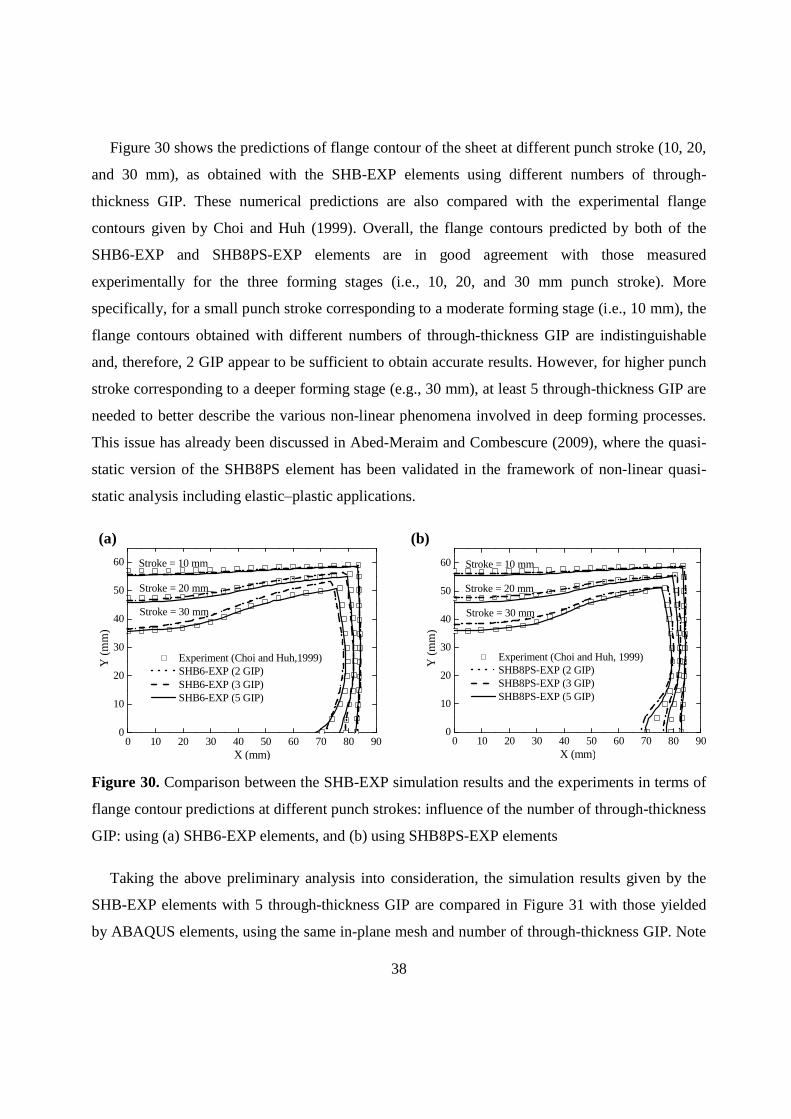
4. Application to the simulation of sheet metal forming processes
In this section, three deep drawing tests with various punch shapes, involving different
materials and associated anisotropy properties, are simulated with the present SHB-EXP elements
in order to evaluate their performance in the context of sheet metal forming simulation. The
obtained results are compared with those given by ABAQUS elements, on the one hand, and with
experimental data taken from the literature, on the other hand.
4.1 Deep drawing of a square cup
The deep drawing of a square cup, initially proposed in Numisheet’93 conference (Makinouchi
et al., 1993), is considered here to further assess the performance of the SHB-EXP elements in the
context of sheet metal forming processes, which involve large plastic deformations, material non-
linearity and anisotropy, and double-sided contact. Note that this benchmark test is very popular
within the sheet metal forming community and, accordingly, it has been investigated by a number
of authors in the literature (see, e.g., Choi and Huh, 1999; Schwarze et al., 2011; Pagani et al.,
2014). The schematic view of the setup and the associated geometric dimensions are shown in
Figure 24.
punch
holder
dieblank
70
74
R5
48
R843
R12
R10
z
x
punchdie
y
x
Figure 24. Schematic view for the square cup drawing setup

32
The initial dimensions of the sheet are 150 mm × 150 mm × 0.81 mm. The sheet metal is made
of an aluminum material whose behavior is described by the Swift isotropic hardening law (see
Table 1) along with a von Mises-type yield criterion. The associated material parameters are
summarized in Table 4.
Table 4. Elastic plastic parameters for the studied aluminum alloy.
All along the forming process, a constant blank holder force of 16.6 kN is applied, and the
friction coefficient between the forming tools and the sheet is taken equal to 0.162 (Makinouchi et
al., 1993). Only one quarter of the problem is discretized, considering the symmetry of the tools
and the sheet.
Figure 25 shows the final deformed drawn of the square cup at the punch displacement of 15
mm, as obtained with the prismatic and hexahedral SHB-EXP elements.
(a)
(b)
Figure 25. Final deformed drawn of the square cup at a punch displacement of 15 mm: using (a)
SHB6-EXP elements, and (b) using SHB8PS-EXP elements
Three final draw-in distances, as illustrated in Figure 26, are analyzed and compared with the
experimental measurements (Makinouchi et al., 1993), where Dx denotes the draw-in distance
along the x-axis, Dy along the y-axis, and Dd the draw-in distance along the diagonal direction.
The in-plane discretization of the square sheet uses 64×64 elements, in the case of quadrilateral
shell or hexahedral elements, and 64×64×2 elements, in the case of triangular shell or prismatic
elements. The sensitivity of the simulation results to the number of through-thickness Gauss

33
integration points (GIP) is also analyzed. For the SHB-EXP elements (SHB6-EXP and SHB8PS-
EXP), ABAQUS shell elements (S3R and S4R), and ABAQUS solid shell elements (SC6R), the
simulations are carried out using 2, 3, and 5 GIP points, successively, with only a single element
layer. However, for ABAQUS solid elements (C3D6 and C3D8R), several element layers are used
to mesh the sheet thickness (i.e., 2, 3 and 5 layers), in order to have a comparable number of GIP.
Note that the SC8R ABAQUS solidshell element failed to simulate the present benchmark test
and, therefore, no predictions are presented for this element.
Figure 26. Illustration of the draw-in distances of the square cup after forming
Figure 27 compares the draw-in distances predicted by the SHB-EXP elements and ABAQUS
elements, for different through-thickness GIP, with the experimental measurements from
Makinouchi et al. (1993). A first observation is that most of the simulation results lie in the range
delimited by the minimum and the maximum draw-in experimental measurements.
For the SHB6-EXP prismatic solidshell element, the simulation results reported in Figures
27(a), (c) and (e) suggest that at least 3 through-thickness GIP should be used to obtain accurate
predictions for this forming process. When this condition is met, the SHB6-EXP element provides
results that fall in the range delimited by the minimum and the maximum draw-in experimental
measurements, and which are the closest to the average draw-in experimental distances. It is worth
noting that the Dx and Dy draw-in distances predicted with the S3R ABAQUS shell element are
overestimated, showing limitations of shell elements in modeling sheet metal forming processes
involving double-sided contact.

34
For the SHB8PS-EXP hexahedral solidshell element (see Figures 27(b), (d) and (f)), the
associated simulation results are comparable to those given by the C3D8R ABAQUS solid
element; however, the latter requires resorting to several element layers in contrast to the proposed
solid shell elements. On the other hand, the predictions using the S4R ABAQUS shell element are
overestimated in most cases, revealing once again the limitations of shell elements in handling
double-sided contact. Finally, the sensitivity study to the number of through-thickness GIP reveals
that only two GIP are sufficient for the SHB8PS-EXP element to accurately describe the various
non-linear through-thickness phenomena.

35
(a)
0
1
2
3
4
5
6
7
8
9
5 GIP3 GIP
C3D6 SC6R S3R SHB6-EXP
Dra
w-in
dis
tan
ce D x (
mm
)
2 GIP
Max. Exp.
Min. Exp.
(b)
0
1
2
3
4
5
6
7
8
9 C3D8R S4R SHB8PS-EXP
Dra
w-in
dis
tan
ce D x (
mm
)
2 GIP 3 GIP 5 GIP
Min. Exp.
Max. Exp.
(c)
0
1
2
3
4
5
6
7
8
9 C3D6 SC6R S3R SHB6-EXP
Dra
w-in
dis
tan
ce D y (
mm
)
Max. Exp.
Min. Exp.
2 GIP 3 GIP 5 GIP
(d)
0
1
2
3
4
5
6
7
8
9 C3D8R S4R SHB8PS-EXP
Dra
w-in
dis
tan
ce D y (
mm
)
2 GIP 3 GIP 5 GIP
Min. Exp.
Max. Exp.
(e)
0
1
2
3
4
5
6 C3D6 SC6R S3R SHB6-EXP
Dra
w-in
dis
tanc
e D d
(mm
)
Max. Exp.
Min. Exp.
2 GIP 3 GIP 5 GIP
(f)
0
1
2
3
4
5
6 C3D8R S4R SHB8PS-EXP
Dra
w-in
dis
tan
ce D d
(mm
)
2 GIP 3 GIP 5 GIP
Min. Exp.
Max. Exp.
Figure 27. Comparison of the draw-in distances at 15 mm punch displacement, as obtained by the
SHB-EXP elements, ABAQUS elements and experimental measurements

36
4.2 Deep drawing of a rectangular cup
The second sheet metal forming test investigated in this work consists in the deep drawing of a
rectangular sheet with tools of rectangular shape. Because of its particular geometric
characteristics, this benchmark problem is known to involve strong non-linearities (due to large
deformations, plasticity, and contact), which are more severe than those encountered in the deep
drawing of a square cup (see subsection 4.1). This test has been previously studied by Choi and
Huh (1999) and Huh and Choi (1999), by considering the Hill’48 quadratic yield criterion for the
plastic anisotropy of the sheet and the Swift law for isotropic hardening. The initial dimensions of
the rectangular sheet are 120 mm × 170 mm × 0.625 mm. The material parameters of the sheet
metal, corresponding to a cold rolled steel, are summarized in Table 5 (see Choi and Huh, 1999),
while the details on the geometry of the forming setup and its dimensions are all reported in Figure
28.
Table 5. Material parameters associated with the anisotropic elastic plastic model for the cold
rolled steel.
The constant blank holder force is set equal to 14.71 kN during the forming process, and the
Coulomb friction coefficient between the forming tools and the sheet is taken equal to 0.11.
Owing to the symmetry, only one quarter of the sheet is modeled, with an in-plane discretization
of 1960 elements for triangular shell or prismatic elements, and 980 elements for quadrilateral
shell or hexahedral elements (see Figure 29 for illustration). In order to determine the appropriate
number of through-thickness GIP, three simulations with 2, 3, and 5 through-thickness GIP,
successively, are first conducted with the SHB-EXP elements.

37
punch
holder
dieblankR6
R6holder
die
z
x
R11
R9
punch
die
y
x
123
120
40
43
Figure 28. Schematic view for the rectangular cup drawing setup
(a)
(b)
Figure 29. Final deformed mesh for the rectangular cup at a punch stroke of 30 mm: using (a)
SHB6-EXP elements, and (b) using SHB8PS-EXP elements
38
Figure 30 shows the predictions of flange contour of the sheet at different punch stroke (10, 20,
and 30 mm), as obtained with the SHB-EXP elements using different numbers of through-
thickness GIP. These numerical predictions are also compared with the experimental flange
contours given by Choi and Huh (1999). Overall, the flange contours predicted by both of the
SHB6-EXP and SHB8PS-EXP elements are in good agreement with those measured
experimentally for the three forming stages (i.e., 10, 20, and 30 mm punch stroke). More
specifically, for a small punch stroke corresponding to a moderate forming stage (i.e., 10 mm), the
flange contours obtained with different numbers of through-thickness GIP are indistinguishable
and, therefore, 2 GIP appear to be sufficient to obtain accurate results. However, for higher punch
stroke corresponding to a deeper forming stage (e.g., 30 mm), at least 5 through-thickness GIP are
needed to better describe the various non-linear phenomena involved in deep forming processes.
This issue has already been discussed in Abed-Meraim and Combescure (2009), where the quasi-
static version of the SHB8PS element has been validated in the framework of non-linear quasi-
static analysis including elasticplastic applications.
(a)
0 10 20 30 40 50 60 70 80 900
10
20
30
40
50
60
Stroke = 30 mm
Stroke = 20 mm
Y (
mm
)
X (mm)
Experiment (Choi and Huh,1999) SHB6-EXP (2 GIP) SHB6-EXP (3 GIP) SHB6-EXP (5 GIP)
Stroke = 10 mm
(b)
0 10 20 30 40 50 60 70 80 900
10
20
30
40
50
60
Stroke = 30 mm
Stroke = 20 mm
Y (
mm
)
X (mm)
Experiment (Choi and Huh, 1999) SHB8PS-EXP (2 GIP) SHB8PS-EXP (3 GIP) SHB8PS-EXP (5 GIP)
Stroke = 10 mm
Figure 30. Comparison between the SHB-EXP simulation results and the experiments in terms of
flange contour predictions at different punch strokes: influence of the number of through-thickness
GIP: using (a) SHB6-EXP elements, and (b) using SHB8PS-EXP elements
Taking the above preliminary analysis into consideration, the simulation results given by the
SHB-EXP elements with 5 through-thickness GIP are compared in Figure 31 with those yielded
by ABAQUS elements, using the same in-plane mesh and number of through-thickness GIP. Note

39
that for the C3D6 and C3D8R ABAQUS solid elements, 5 element layers are required, which
leads to 9800 elements and 4900 elements, respectively. Figure 31 shows the flange contour
predictions at different punch stroke, as obtained with the SHB-EXP and ABAQUS elements,
along with the experimental measurements. It can be seen that, in the case of small punch stroke
(i.e., punch stroke of 10 mm), the flange contours predicted with the SHB-EXP elements and
ABAQUS elements are quite equivalent, whereas the SHB-EXP elements provide the closest
results to the experiments in the case of deep forming (i.e., punch stroke of 30 mm). These results
clearly demonstrate the capability of the proposed SHB-EXP elements of accurately describing the
various through-thickness phenomena using only a single element layer with few GIP.
(a)
0 10 20 30 40 50 60 70 80 900
10
20
30
40
50
60
Stroke=30mm
Stroke=20mm
Y (
mm
)
X (mm)
Experiment (Choi and Huh,1999) SHB6-EXP (5 GIP) S3R (5 GIP) SC6R (5 GIP) C3D6 (5 GIP with 5 layers)
Stroke=10mm
(b)
0 10 20 30 40 50 60 70 80 900
10
20
30
40
50
60
Stroke=30mm
Stroke=20mm
Y (
mm
)
X (mm)
Experiment (Choi and Huh, 1999) SHB8PS-EXP (5 GIP) S4R (5 GIP) SC8R (5 GIP) C3D8R (5 GIP with 5 layers)
Stroke=10mm
Figure 31. Prediction of flange contours at different punch strokes: comparison between the SHB-
EXP simulation results using 5 through-thickness GIP, ABAQUS element results, and
experimental measurements; (a) triangular shell / prismatic elements, and (b) quadrilateral shell /
hexahedral elements
4.3 Deep drawing of a cylindrical cup
The deep drawing of cylindrical cup is another popular benchmark test commonly used to study
the earing evolution after forming, when the anisotropic plastic behavior of sheet metals is
considered. In the present test, deep drawing of a circular plate made of an AA2090-T3 aluminum
alloy is investigated. The initial diameter and thickness of the sheet metal are equal to 158.76 mm
and 1.6 mm, respectively. All additional details regarding the process simulation and the
experimental results are taken from Yoon et al. (2006). The Swift law (see Table 1) is considered

40
here to describe the isotropic hardening behavior, while the Hill’48 yield criterion is adopted to
model the anisotropic plasticity of the sheet metal. The corresponding material parameters are
summarized in Table 6. The geometry of the drawing setup and the associated dimensions are all
illustrated in Figure 32.
Table 6. Material parameters for the AA2090-T3 aluminum alloy.
punch
holder
die
blank
97.46
101.48R12.7
158.76
R12.7
Figure 32. Schematic view for the cylindrical cup drawing setup
Due to symmetry considerations, only one quarter of the circular sheet is modeled, with an in-
plane discretization of 1350 elements, in the case of triangular shell or prismatic elements, and 800
elements, in the case of quadrilateral shell or hexahedral elements. A constant holder force of 22.2
kN is applied during the forming process, and the friction coefficient between the sheet and the
forming tools is taken to be equal to 0.1. The deformed cup, corresponding to the end of the
forming operation, is illustrated in Figure 33 for both of the SHB6-EXP and SHB8PS-EXP
elements. Similar to the previous deep drawing benchmarks, the influence of the number of
through-thickness GIP is also investigated in this test by adopting a single SHB-EXP element
layer with 2, 3, and 5 through-thickness GIP, successively. The cup height profile predictions
obtained with the SHB-EXP elements and ABAQUS elements are reported in Figure 34, for the
quarter model, and compared with the experimental measurements taken from Yoon et al. (2006).
On the whole, it can be observed that both the shape and the height of the earing profiles predicted

41
with the SHB-EXP elements are in good agreement with the experiments. However, these
predictions are slightly underestimated at 0° and 90° from the rolling direction, while they are
closer to the experiments in the range around the experimental peak value at 50° from the rolling
direction. From the sensitivity study to the number of through-thickness GIP, the SHB8PS-EXP
element shows good convergence of the results starting from 2 GIP, while the SHB6-EXP element
requires at least 3 through-thickness GIP to provide converged results. Furthermore, Figure 34
shows comparisons between the earing profiles predicted with the SHB-EXP elements and
ABAQUS elements, using the same in-plane mesh and a comparable number of through-thickness
GIP. It can be clearly observed that the SHB-EXP elements provide the closest predictions to the
experiments, for almost the entire range of angles from the rolling direction. However, the current
predictions may be improved in future work by adopting more appropriate anisotropic yield
criteria for aluminum alloys (see, e.g., Barlat et al. 1991; Barlat et al., 2003; Yoon et al., 2006),
which are able to predict more than four earing profiles for the complete circular sheet, as
observed experimentally for such materials.
(a) (b)
Figure 33. Final deformed mesh for the cylindrical cup: using (a) SHB6-EXP elements, and (b)
using SHB8PS-EXP elements

42
(a)
0 10 20 30 40 50 60 70 80 9035.0
37.5
40.0
42.5
45.0
47.5
50.0
52.5
55.0
C3D6 (5 GIP with 5 layers) S3R (5 GIP) SC6R (5 GIP)
Experiment (Yoon et al., 2006) SHB6-EXP (2 GIP) SHB6-EXP (3 GIP) SHB6-EXP (5 GIP)
Angle from the rolling direction (deg.)
Cup
he
igh
t (m
m)
(b)
0 10 20 30 40 50 60 70 80 9035.0
37.5
40.0
42.5
45.0
47.5
50.0
52.5
55.0
C3D8R (5 GIP with 5 layers) S4R (5 GIP) SC8R (5 GIP)
Experiment (Yoon et al., 2006) SHB8PS-EXP (2 GIP) SHB8PS-EXP (3 GIP) SHB8PS-EXP (5 GIP)
Angle from the rolling direction (deg.)
Cu
p he
igh
t (m
m)
Figure 34. Prediction of cup height profiles: comparison between the SHB-EXP simulation
results, ABAQUS element results, and experimental measurements; (a) triangular shell / prismatic
elements, and (b) quadrilateral shell / hexahedral elements
5. Conclusion
In this paper, two linear solidshell elements, namely a six-node prismatic element denoted
SHB6-EXP and an eight-node hexahedral element denoted SHB8PS-EXP, have been proposed
and implemented into the dynamic finite element code ABAQUS/explicit. The main objective of
this work is to establish accurate and efficient solid shell element formulations for the
explicit/dynamic analysis of 3D thin structures. These explicit solidshell versions, denoted SHB-
EXP, can be applied to structural dynamic analysis, such as impact/crash problems, as well as to
complex sheet metal forming processes, for which the use of implicit/quasi-static approaches may
exhibit convergence issues.
Several numerical treatments, such as the reduced-integration technique, the assumed-strain
method, hourglass mode stabilization, are adopted in the formulation of the SHB-EXP elements to
eliminate the main locking phenomena that are inherent in low-order formulations. A
characteristic feature is that these elements are based on a fully three-dimensional approach, with
only translational degrees of freedom. In addition, they are designed to be used with only a single
element layer, while attributing an arbitrary user-defined number of integration points in the
thickness direction. This makes them very attractive, due to their computational efficiency in
explicit/dynamic analyses.

43
The performance of the SHB-EXP elements has been first shown through popular dynamic
benchmark tests, involving geometric and material non-linearities. In particular, the SHB-EXP
elements demonstrate good capabilities for the modeling of impact-type problems, in both cases of
low and high initial velocity of projectiles. The simulation results obtained with the proposed
SHB-EXP elements have been validated by comparison with state-of-the-art elements available in
ABAQUS, and were also found in good agreement with reference solutions taken from the related
literature.
Then, these explicit versions of solidshell elements have been validated in the context of sheet
metal forming applications. Three popular and selective deep drawing processes have been
considered in this work, using square, rectangular, and circular anisotropic sheet metals associated
with square, rectangular, and cylindrical punch shapes, respectively. These challenging benchmark
problems allow evaluating the SHB-EXP elements in severe forming conditions, involving non-
linear loading paths, anisotropic material behavior, and double-sided contact. Using similar
meshes and comparable numbers of integration points through the thickness, the comparison
between conventional ABAQUS solid elements and the present SHB-EXP elements reveals that
the latter provide predictions that are the closest to the experimental results. It is worth noting that
the good performance of the SHB-EXP elements is achieved using only a single element layer
with few integration points, in contrast to ABAQUS solid elements, which has important
consequences on the computational cost. Note also that some convergence issues have been
encountered with the SC8R ABAQUS solidshell element for the modeling of the deep drawing
of a square cup, which makes the present SHB8PS-EXP solid shell element very competitive in
such benchmark problems.
On the whole, the performance of the SHB8PS-EXP hexahedral element is better than that of
the SHB6-EXP prismatic element. However, these two solid-shell element complement each other,
as combination of these may prove necessary for the simulation of complex shaped geometries,
which cannot be discretized using only hexahedral elements. Similar situations may also be
encountered when using free mesh-generation tools, which results in meshes comprising both
hexahedral and prismatic elements.

44
References
Abed-Meraim F. and Combescure A. (2002), “SHB8PS—a new adaptive, assumed-strain
continuum mechanics shell element for impact analysis”, Computers and Structures, Vol. 80
Nos 9-10, pp. 791-803.
Abed-Meraim F. and Combescure A. (2009), “An improved assumed strain solidshell element
formulation with physical stabilization for geometric non-linear applications and
elastic plastic stability analysis”, International Journal for Numerical Methods in
Engineering, Vol. 80 No 13, pp. 1640-1686.
Balmer H.A. and Witmer E.A. (1964), Theoretical-experimental correlation of large dynamic and
permanent deformations of impulsively-loaded simple structures, Air Force Flight Dynamics
Laboratory, Rept. FDP-TDR-64-108, Wright Patterson AFB, OH
Barlat F., Brem J.C., Yoon J.W., Chung K., Dick R.E., Lege D.J., Pourboghrat F., Choi S.H. and
Chu E. (2003), “Plane stress yield function for aluminum alloy sheets – part 1: theory”,
International Journal of Plasticity, Vol. 19 No 9, pp. 1297-1319.
Barlat F., Lege D.J. and Brem J.C. (1991), “A six-component yield function for anisotropic
materials”, International Journal of Plasticity, Vol. 7 No 7, pp. 693-712.
Belytschko T., Bindeman L.P. (1993), “Assumed strain stabilization of the eight node hexahedral
element”, Computer Methods in Applied Mechanics and Engineering, Vol. 105 No 2, pp.
225-260.
Belytschko T., Lin J.I. and Tsay C.S. (1984), “Explicit algorithms for the nonlinear dynamics of
shells”, Computer Methods in Applied Mechanics and Engineering, Vol. 42 No 2, pp. 225-
251.
Belytschko T., Wong B.L. and Chiang H.Y. (1992), “Advances in one-point quadrature shell
elements”, Computer Methods in Applied Mechanics and Engineering, Vol. 96, pp. 93-107.
Cardoso R.P.R., Yoon J.W., Mahardika M., Choudhry S., Alves de Sousa R.J. and Fontes Valente
R.A. (2008), “Enhanced assumed strain (EAS) and assumed natural strain (ANS) methods
for one-point quadrature solid-shell elements”, International Journal for Numerical Methods
in Engineering, Vol. 75 No 2, pp. 156-187.

45
Chen L.B., Xi F. and Yang J.L. (2007), “Elastic-plastic contact force history and response
characteristics of circular plate subjected to impact by a projectile”, Acta Mechanica Sinica,
Vol. 23 No 4, pp. 415-425.
Cho C., Park H.C. and Lee S.W. (1998), “Stability analysis using a geometrically nonlinear
assumed strain solid shell element model”, Finite Elements in Analysis and Design, Vol. 29
No 2, pp. 121-135.
Choi T.H. and Huh H. (1999), “Sheet metal forming analysis of planar anisotropic materials by a
modified membrane finite element method with bending effect”, Journal of Materials
Processing Technology, Vol. 89-90, pp. 58-64.
Edem I.B. and Gosling P.D. (2013), “Physically stabilised displacement-based ANS solid-shell
element”, Finite Element in Analysis and Design, Vol. 74, pp. 30-40.
Flores F.G. (2013), “Development of a non-linear triangular prism solid-shell element using ANS
and EAS techniques”, Computer Methods in Applied Mechanics and Engineering, Vol. 266,
pp. 81-97.
Guo Y.Q., Gati W., Naceur H. and Batoz J.L. (2002), “An efficient DKT rotation free shell
element for springback simulation in sheet metal forming”, Computers and Structures, Vol.
80 Nos 27-30, pp. 2299-2312.
Hallquist J.O. (1983), Theoretical manual for DYNA3D, Report UC1D-19041, Lawrence
Livermore National Laboratory, Livermore, CA, USA
Hauptmann R. and Schweizerhof K. (1998), “A systematic development of Solid-shell element
formulations for linear and non-linear analyses employing only displacement degrees of
freedom”, International Journal for Numerical Methods in Engineering, Vol. 42 No 1, pp.
49-69.
Hill R. (1948), “A theory of the yielding and plastic flow of anisotropic metals”, Proc. Roy. Soc.
London A, Vol. 193 No 1033, pp. 281-297.
Huh H. and Choi T.H. (1999), “Modified membrane finite element formulation for sheet metal
forming analysis of planar anisotropic materials”, International Journal of Mechanical
Sciences, Vol. 42 No 8, pp. 1623-1643.

46
Huh H., Han S.S. and Yang D.Y. (1994), “Modified membrane finite element formulation
considering bending effects in sheet metal forming analysis”, International Journal of
Mechanical Sciences, Vol. 36 No 7, pp. 659-671.
Li L.M., Peng Y.H. and Li D.Y. (2011), “A stabilized underintegrated enhanced assumed strain
solid-shell element for geometrically nonlinear plate/shell analysis”, Finite Element in
Analysis and Design, Vol. 47 No 5, pp. 511-518.
Lu H., Ito K., Kazama K. and Namura S. (2006), “Development of a new quadratic shell element
considering the normal stress in the thickness direction for simulating sheet metal forming”,
Journal of Materials Processing Technology, Vol. 171 No 3, pp. 341-347.
Makinouchi A., Nakamachi E., Oñate E. and Wagoner R.H. (1993), “NUMISHEET’93”,
Proceedings of the 2nd International Conference and Workshop on Numerical Simulation of
3D Sheet Metal Forming Processes - Verification of Simulation with Experiment, Isehara,
Japan
Mars J., Wali M., Jarraya A., Dammak F. and Dhiab A. (2015), “Finite element implementation of
an orthotropic plasticity model for sheet metal in low velocity impact simulations”, Thin-
Walled Structures, Vol. 89, pp. 93-100.
Olovsson L., Unosson M. and Simonsson K. (2004), “Selective mass scaling for thin walled
structures modeled with tri-linear solid elements”, Computational Mechanics, Vol. 34 No 2,
pp. 134-136.
Pagani M., Reese S. and Perego U. (2014), “Computationally efficient explicit nonlinear analyses
using reduced integration-based solid-shell finite elements”, Computer Methods in Applied
Mechanics and Engineering, Vol. 268, pp. 141-159.
Parente M.P.L., Fontes Valente R.A., Natal Jorge R.M., Cardoso R.P.R. and Alves de Sousa R.J.
(2006), “Sheet metal forming simulation using EAS solid-shell finite elements”, Finite
Element in Analysis and Design, Vol. 42 No 13, pp. 1137-1149.
Puso M.A. (2000), “A highly efficient enhanced assumed strain physically stabilized hexahedral
element”, International Journal for Numerical Methods in Engineering, Vol. 49 No 8, pp.
1029-1064.
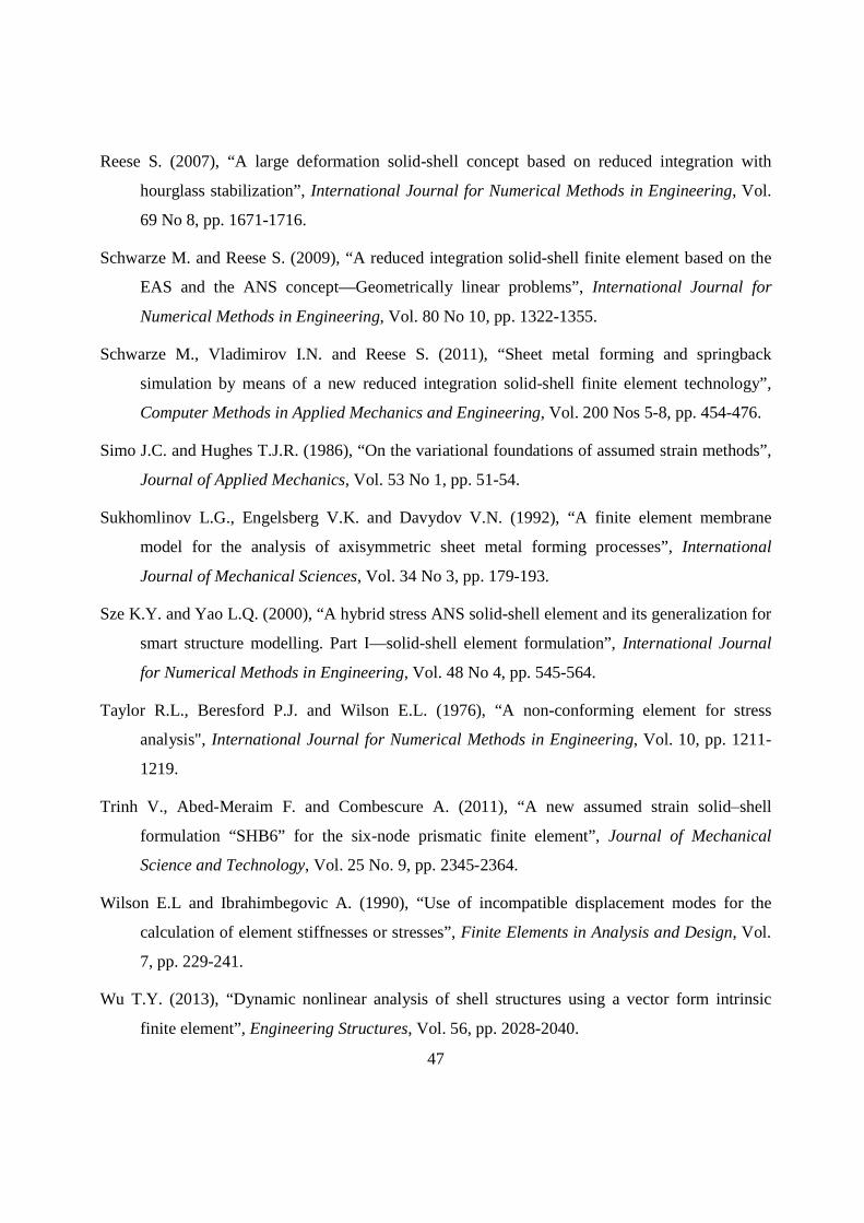
47
Reese S. (2007), “A large deformation solid-shell concept based on reduced integration with
hourglass stabilization”, International Journal for Numerical Methods in Engineering, Vol.
69 No 8, pp. 1671-1716.
Schwarze M. and Reese S. (2009), “A reduced integration solid-shell finite element based on the
EAS and the ANS concept—Geometrically linear problems”, International Journal for
Numerical Methods in Engineering, Vol. 80 No 10, pp. 1322-1355.
Schwarze M., Vladimirov I.N. and Reese S. (2011), “Sheet metal forming and springback
simulation by means of a new reduced integration solid-shell finite element technology”,
Computer Methods in Applied Mechanics and Engineering, Vol. 200 Nos 5-8, pp. 454-476.
Simo J.C. and Hughes T.J.R. (1986), “On the variational foundations of assumed strain methods”,
Journal of Applied Mechanics, Vol. 53 No 1, pp. 51-54.
Sukhomlinov L.G., Engelsberg V.K. and Davydov V.N. (1992), “A finite element membrane
model for the analysis of axisymmetric sheet metal forming processes”, International
Journal of Mechanical Sciences, Vol. 34 No 3, pp. 179-193.
Sze K.Y. and Yao L.Q. (2000), “A hybrid stress ANS solid-shell element and its generalization for
smart structure modelling. Part —solid-shell element formulation”, International Journal
for Numerical Methods in Engineering, Vol. 48 No 4, pp. 545-564.
Taylor R.L., Beresford P.J. and Wilson E.L. (1976), “A non-conforming element for stress
analysis", International Journal for Numerical Methods in Engineering, Vol. 10, pp. 1211-
1219.
Trinh V., Abed-Meraim F. and Combescure A. (2011), “A new assumed strain solidshell
formulation “SHB6” for the six-node prismatic finite element”, Journal of Mechanical
Science and Technology, Vol. 25 No. 9, pp. 2345-2364.
Wilson E.L and Ibrahimbegovic A. (1990), “Use of incompatible displacement modes for the
calculation of element stiffnesses or stresses”, Finite Elements in Analysis and Design, Vol.
7, pp. 229-241.
Wu T.Y. (2013), “Dynamic nonlinear analysis of shell structures using a vector form intrinsic
finite element”, Engineering Structures, Vol. 56, pp. 2028-2040.

48
Yoon J.W., Barlat F., Dick R.E. and Karabin M.E. (2006), “Prediction of six or eight ears in a
drawn cup based on a new anisotropic yield function”, International Journal of Plasticity,
Vol. 22 No 1, pp. 174-193.
Zienkiewicz O.C., Taylor R.L. and Zhu J.Z. (2006), The Finite Element Method, sixth ed.,
Elsevier Ltd.