experiments using a helium-neon laser · pdf fileindustrial fiber optics experiments using a...
TRANSCRIPT
INDUSTRIAL FIBER OPTICS
EXPERIMENTS USING AHELIUM-NEON LASER
A REFERENCE MANUAL AND EXPERIMENT GUIDE
FOR USE WITH INDUSTRIAL FIBER OPTICS
HELIUM-NEON LASERS AND OPTICS EDUCATION SETS
THIRTEENTH EDITION
BASED ON INSTRUCTION DEVELOPED BY HERBERT H. GOTTLIEB
PHYSICS TEACHER; CURRICULUM CONSULTANT
NEW YORK STATE DEPARTMENT OF EDUCATION
© 1973, 1974, 1975, 1976, 1977, 1978, 1979, 1980, 1981, 2000
PN 45-700[REF 00-00560]
JUNE 2006
2
SAFETY NOTESLasers create a very special type of light that guarantees exciting laboratory experiments and visual demonstrations for inquiring young minds.
Industrial Fiber Optics (IFO) helium-neon lasers emit a beam of visible orange-red light. They do not emit invisible, exotic, or otherwise harmfulradiation.
IFO low power lasers have a light output of only a few thousandths of a watt and shouldn’t be confused with the powerful commercial lasers usedfor burning, cutting and drilling.
Even so, the laser beam must be treated with caution and common sense because it is intense and concentrated. The greatest potential for harmwith IFO lasers is to the eyes. No one should look directly into the laser beam or stare at its bright reflections, just as no one should stare at the sun.
The United States Department of Health, Education and Welfare regulates the manufacture of lasers to ensure users are not endangered. The fed-eral government classifies lasers according to their power levels and specifies appropriate safety features for each level. Demonstration lasers fall intoClass II and can be identified by a yellow CAUTION label that contains the warning, Do not stare into beam along with a universal laser warningsymbol. Class II lasers have a maximum power of 1/1000th of a watt, a power judged to be eye-safe, except possibly in case of deliberate, long-term direct staring into the beam. Safety features include a pilot lamp that glows when the electrical power is ON and a mechanical beam-stop thatblocks the beam when power is on. In addition, IFO observes safety directives issued by the European Standards Committee for optical and elec-trical safety, including directives 89/336/EEC and 92/59/EEC for lasers and EN 71-1 for optics kits.
Laser Safety
1. Instruct students not to look into the laser or stare at bright mirror-like reflections of the beam.2. Remove all bright mirror-like objects from the work area, including rings, watches, metal bands and tools. Beam reflections can be nearly as
intense as the original beam.3. Block off the beam at a point beyond the farthest point of interest. Use a dull, non-reflective object, such as a piece of wood. 4. If the beam must travel a long distance, keep it directed close to the ground or overhead so it does not cross walkways at eye level. 5. Never use magnifiers such as binoculars or telescopes to look at the beam as it travels or when it strikes a surface6. Never allow unauthorized people to handle lasers; store them in a safe place away from unauthorized users.7. Lasers are not toys, use them only for educational purposes.8. Never point a laser at anyone, no matter how far away.9. Make sure the laser is always secured on a solid foundation. Keep power cords and adapters away from areas where they can be acciden
tally disturbed.10. Helium-neon lasers employ high voltages. The power supply retains potentially harmful voltage for periods after the input power has ceased.
Never open the housing and expose anyone to these voltages.11. Keep these safety regulations near the laser, and read and refer to them in case of safety questions.12. If you have any other safety questions, please contact Industrial Fiber Optics at (480) 804-1227 or [email protected].
General Safety
1. Since optics kits contain glass pieces, it is important to remember that they can present a cutting hazard. Please handle them carefully and make sure that you don’t contact any edges that might cut you.
2. To fully utilize this manual and its safety warnings, we recommend that the manual be kept close to the optics lab.
Electrical Safety
If the laser housing is opened, IFO’s warranty is void.
Each laser is equipped with a UL-approved line cord and 3-prong grounded plug. ALWAYS PLUG THE LASER INTO A GROUNDED OUTLET.
For further information about laser safety and the federal regulations involved, contact the Compliance Officer at the Bureau of Radiological Health,Public Health Service, Food & Drug Administration, Rockville, MD 20857. Telephone: [301] 443-4874. Ask for Regulation Publication HHS PUBFDA 80-80356.

3
TABLE OF CONTENTS
Safety Notes ...................................................................................................................................................................................2
Introduction....................................................................................................................................................................................4
Equipment Included in the Optics Education Kit ...........................................................................................................................5
Hints on Using Accessories for Experiments ...............................................................................................................................10
What is a Laser? ...........................................................................................................................................................................12
Theory of IFO HeNe Laser Operation..........................................................................................................................................17
Experiment 1. Color ................................................................................................................................................................20
Experiment 2. Ophthalmology.................................................................................................................................................22
Experiment 3. Polarization Effects...........................................................................................................................................23
Experiment 4. Measuring the Index of Refraction of Glass .....................................................................................................24
Experiment 5. Index of Refraction of a Prism..........................................................................................................................25
Experiment 6. Beam Divergence and Convergence by Lenses ................................................................................................26
Experiment 7. Foucault Knife-Edge Test..................................................................................................................................27
Experiment 8. Knife-edge and Single Slit Diffraction ...............................................................................................................28
Experiment 9. Double Slit Diffraction ......................................................................................................................................29
Experiment 10. Multiple Slit Diffraction Using Gratings............................................................................................................30
Experiment 11. Interference by Multiple Internal Reflections in Glass.....................................................................................31
Experiment 12. Lloyd’s Mirror...................................................................................................................................................32
Experiment 13. Michelson Interferometer (Elementary Form) .................................................................................................34
Experiment 14. Thin Film in Interference Using an Air Wedge ................................................................................................36
Experiment 15. Diffraction from Small Holes ............................................................................................................................37
Experiment 16. Observing Holograms .......................................................................................................................................38
Experiment 17. Spatial Filtering.................................................................................................................................................39
Experiment 18. Diffraction Patterns from a Ruler......................................................................................................................40
Experiment 19. Measuring the Curvature of the Earth..............................................................................................................41
Experiments that can be performed in their entirety with the addition of an IFO 45-610 Optional Accessories Kit
Experiment 20. Beam Intensity..................................................................................................................................................43
Experiment 21. Divergence of a Laser Beam .............................................................................................................................44
Experiment 22. Laser Scanning .................................................................................................................................................45
Experiment 23. Light Pipes and Fiber Optics ............................................................................................................................47
Experiment 24. The Colors in a Rainbow..................................................................................................................................48
Experiment 25. Reflection .........................................................................................................................................................50
Experiment 26. Measuring the Critical Angle............................................................................................................................51
Experiment 27. Measuring the Index of Refraction of Liquids ..................................................................................................52
Experiment 28. Diffraction Technique for Measuring Index of Refraction ................................................................................53
Experiment 29. Doppler Effect ..................................................................................................................................................54
Additional Experiments for Advanced Study
Experiment 30. Scattering of Light.............................................................................................................................................56
Experiment 31. Measuring the Index of Refraction of a Gas .....................................................................................................57
Experiment 32. Amplification of Movement ..............................................................................................................................59
Experiment 33. Alignment.........................................................................................................................................................60
Experiment 34. Measuring the Speed of Light...........................................................................................................................62
Additional Industrial Fiber Optics Education Kits & Other Products............................................................................................65
Cleaning Instructions ...................................................................................................................................................................68

4
INTRODUCTION
Thank you for selecting this Industrial Fiber Optics science education kit. The kit builds on an earlier edition devel-
oped by Metrologic, Inc., and acquired by Industrial Fiber Optics. The newer version incorporates technology
updates that offer cutting edge content for today’s young experimenters and scientists of the future.
This manual contains experiments that have been developed by active teachers and thoroughly tested in the class-
room. The experiments may be performed using mirrors, lenses, filters and other items already found in schools.
Information about Industrial Fiber Optics’ other educational laser and fiber optics kits and a full array of comple-
mentary and replacement products can be found at the end of this manual.

5
EQUIPMENT INCLUDED IN THEOPTICS EDUCATION KIT
Industrial Fiber Optics’ Laser Optics Kit (45-600) contains the basic optical components to perform most of the experiments in this manual. TheLaser Optics Kit features magnetic holders called “Maggie” Mounts. These mounts permit fast experimental set-ups that are readily adjusted andaligned, yet retain their positions once in place. The catalog number of each item is listed in the table below. To help identify lenses and other opti-cal components in the kit, approximate dimensions and focal lengths are provided here. Exact characteristics for any item must be determined byexperiment.
Experiments Book
This laboratory manual contains instructionsfor performing experiments using IFO heli-um-neon lasers. The manual also explainssafety, the theory of laser operation and howlasers are made.
No. 45-700 Qty. 1
U-Shaped Carrier
This is a tall carrier with two vertical postsabout 3 cm apart and a magnetic base. Itssteel surface allows other components to beattached magnetically.
No. 45-649Qty. 4
Optical Platform
This 30x20x0.2cm steel platform provides a work surface that holds the magnetic componentholders securely. A center hole in the platform allows it to be bolted to a 60155 Blank Carrier (notincluded) if the user decides to mount the platform on the IFO triangular optics bench system.
No. 45-648 Qty. 1
L-Shaped Carrier
A short carrier with a magnetic base. It is mostoften used in conjunction with the U-shapedcarrier to provide x-y-z axis movement for posi-tioning optics.
No. 45-650 Qty. 2
Magnetic Strips
These 15cm long strips have an adhesive back-ing. They can be cut with scissors and attachedto filters, mirrors, glass prism, etc. so theseobjects can be held magnetically on the carri-ers below.
No. 45-660 Qty. 2
Optical Table and Component Holders
1540.eps
Small Plano-Convex Lens on aCircular Magnetic Mount
This lens expands the beam forviewing holograms and forexperiments where a widebeam is desired. When theoptic mount adapter (below) is used, the mag-net allows the lens to be attached directly tothe laser. This lens has a focal length of approx-imately +7mm.
No. 45-632 Qty. 1
Lenses and Mirrors
6
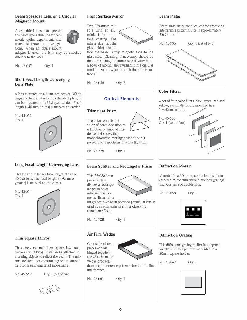
Long Focal Length Converging Lens
This lens has a longer focal length than the45-652 lens. The focal length (+70mm orgreater) is marked on the carrier.
No. 45-654Qty. 1
Front Surface Mirror
Two 25x38mm mir-rors with an alu-minized front sur-face coating. Themirror side (not theglass side) shouldface the beam. Apply magnetic tape to theglass side. (Cleaning, if necessary, should bedone by holding the mirror side downward ina bowl of alcohol and swirling it in a circularmotion. Do not wipe or touch the mirror sur-face.)
No. 45-646 Qty. 2
Thin Square Mirror
These are very small, 1 cm square, low massmirrors (set of two). They can be attached tovibrating objects to reflect the beam. The mir-rors are useful for constructing optical ampli-fiers for magnifying small movements.
No. 45-669 Qty. 1 (set of two)
Triangular Prism
The prism permits thestudy of beam deviation asa function of angle of inci-dence and shows thatmonochromatic laser light cannot be dis-persed into a spectrum as white light can.
No. 45-726 Qty. 1
Beam Splitter and Rectangular Prism
This 25x38x6mmpiece of glassdivides a rectangu-lar prism beaminto two compo-nents. Because itslong sides have been polished parallel, it can beused as a rectangular prism for observingrefraction effects.
No. 45-728 Qty. 1
Air Film Wedge
Consisting of twopieces of glasshinged together,the 25x45mm airwedge producesdramatic interference patterns due to thin filminterference.
No. 45-661 Qty. 1
Diffraction Grating
This diffraction grating replica has approxi-mately 530 lines per mm. Mounted in a50mm square holder.
No. 45-667 Qty. 1
Short Focal Length ConvergingLens Plate
A lens mounted on a 6 cm steel square. Whenmagnetic tape is attached to the steel plate, itcan be mounted on a U-shaped carrier. Focallength (+40 mm or less) is marked on carrier.
No. 45-652Qty. 1
Optical Elements
Beam Plates
These glass plates are excellent for producinginterference patterns. Size is approximately25x75mm.
No. 45-736 Qty. 1 (set of two)
Color Filters
A set of four color filters: blue, green, red andyellow, each individually mounted in a50x50mm mount.
No. 45-656Qty. 1 (set of four)
Diffraction Mosaic
Mounted in a 50mm-square hole, this photo-etched film contains three diffraction gratingsand four pairs of double slits.
No. 45-658 Qty. 1
25X25 25X35 25X50 50X50
INDUSTRIAL FIBER OPTICS P/N IF-510-RD6
Beam Spreader Lens on a CircularMagnetic Mount
A cylindrical lens that spreadsthe beam into a thin line for geo-metric optics experiments andindex of refraction investiga-tions. When an optics mountadapter is used, the lens may be attacheddirectly to the laser.
No. 45-657 Qty. 1

7
Mechanical Parts
Threaded Steel Cell
With 3/4”-32 TPI threads, the steel cell canbe screwed into the optics mount on IFOlasers. Once in place, its steel surface permitsmagnetic mounting of the 7mm plano-convexlens and the beam spreader lens, both ofwhich are mounted on circular magnets.
No. 45-595 Qty. 1
Transmission Hologram
This 50x70mm holographic film has beenexposed and developed. When illuminatedwith laser light and viewed from the properangle, a three-dimensional view results.
No. 45-624 Qty. 1
Fiber Optics Light Guide
The 2-meter-long glass fiber guides the beamin straight or curved paths by means of inter-nal reflection.
No. 45-747 Qty. 1
Polarizing Filter
This pair of 50x50mm filters is used for ana-lyzing the polarization of light and for study-ing polarization effects in laser light output.
No. 45-655Qty. 1 (set oftwo)
0
1
2
3
4
5
6
01
23
45
67
89
10 11 12 13 1415
1560.eps
Ruler
A clear plastic graduated scale used to measure distancesbetween optical components and spaces between interfer-ence fringes.
No. 45-322 Qty. 1
Razor Blades
These blades have sharp well-defined edgesthat are used to block portions of a laserbeam for diffraction experiments.
No. 45-662 Qty. 2
Aluminum Foil and Sewing Needle
These aluminum foil sheets and needle are used to fabricate small pinholes used to cleanup a focused laser beam and for diffraction experiments.
No. 45-663 Qty. 10 sheets of aluminum foil1 sewing needle

8
1561.eps
Storage Case and Foam Set
This fitted case holds all of the items in the 45-600 set.
The 3-piece foam set fits inside the storage case to cushion and protectoptical components. If re-ordering, please specify foam set for 45-600Laser Optics Lab.
No. 45-468 Qty. 1

9
Table 1. Common Abbreviations Used in this Manual
Table 2. Metric Prefixes and Their Meanings
Abbreviation Long version Scientific Notation
tera T 1012 (trillion)
giga G 109 (billion)
mega M 106 (million)
kilo k 103 (thousand)
hecto h 102 (hundred)
deca da 101 (ten)
deci d 10-1 (tenth)
centi c 10-2 (hundredth)
milli m 10-3 (thousandth)
micro µ 10-6 (millionth)
nano n 10-9 (billionth)
pico p 10-12 (trillionth)
fernto f 10-15 (quadrillionth)
Prefix Symbol Multiple
mW milliwatts 1 x 10⁻³ watts
µW microwatts 1 x 10⁻⁶ watts
nW nanowatts 1 x 10⁻⁹ watts
mm millimeters 1 x 10⁻³ meters
µm micrometers 1 x 10⁻⁶ meters
nm nanometers 1 x 10⁻⁹ meters

10
Overview
While designing new types of lasers and optical components, our engi-neers first devised makeshift magnetic mountings for their own conven-ience.
These mounts were effective and saved considerable time in setting upexperiments and holding laser optical accessories at correct angles forexploratory work. It was only natural that we make them available toschools and research laboratories as standard catalog items. Engineersdubbed them “Maggie Mounts” and the name stuck.
Maggie mounts are chrome steel. In use, they mount on a heavy flatplatform of rigid steel that has been plated black to reduce any unwant-ed reflections.
Although you will probably discover many new ways to use thesemountings in your experiments, here are several helpful suggestions forgetting started:
A. Mounting lenses on U-shaped component carriers
Attach lenses so corners of the mount protrude from the top and sidesof the carrier. Corners can be grasped to adjust lens position.
HINTS ON USING ACCESSORIES FOR EXPERIMENTSB. Mounting optics components over the laser aperture
The magnetic tape supplied with the kit can be attached to the front ofthe laser as shown in the illustration. It will hold any of the lenses orbeam spreaders in front of the laser aperture without the need for addi-tional component carriers.
For a more permanent holder use the optional optics accessory mount(part # 45-595) which screws directly into the laser aperture.
1562.eps
Open
AVOID EXPOSURE
LASER RADIATION IS EMITTED
FROM THIS APERTURE.
1563.eps
Open
AVOID EXPOSURE
LASER RADIATION IS EMITTED
FROM THIS APERTURE.
1564.eps

11
C. Making magnetic mounting for small optics parts
The small optical components furnished with the Optics Education Kithave no factory mountings. They can be held in place with a smallamount of the putty included in the kit, or you can easily make yourown magnetic mountings by using the adhesive magnetic tape supplied.This tape can be cut with scissors, or scored with a knife and then bro-ken along the score mark. Remove the paper backing from the tape andpress the adhesive side against the desired surface. Be careful not totouch or contaminate the adhesive once the protective paper has beenremoved
Examples of Attaching Magnetic Tape to Components
DD.. Universal Mirror Mount on U-shaped Carrier
Clamp a Maggie Mount L Carrier to a Maggie Mount U-shaped com-ponent carrier. Stick the rear of the mirror to the protruding section ofthe L carrier. To position the mirror along a horizontal plane, rotate theentire carrier on the Maggie Mount platform. Rotate only the L carrierto position the mirror in a vertical plane.
1566.eps
Razor Blade
Front surface mirror. Apply tapeover entire rear surface.
Polaroid and Color Filters,diffraction gratings
Beam Splitter
1565.eps
12
WHAT IS A LASER?
WAVELENGTH
.00001 nm
.0001
.001
.01
.1
1.0
10
100
1000
10000
1.0
10
100
1000
10000
.01 cm
.1
••••••••••••••••••
••
•••••••
•••••••
••••••••
••••••••
••••
••
••••
••
••••••••••••••••
••
•••••••••••••••••••••
Cosmic Rays
Gamma Rays
X Rays
Ultraviolet
VISIBLEInfrared
Millimeter Waves
Microwaves
TV and FM
Shortwave
AM Broadcast
400 nm
500 nm
600 nm
700 nm
Violet
Blue
GreenYellow
Orange
Red
1567.eps
The term "laser" is an acronym. It stands for "Light Amplification byStimulated Emission of Radiation". So the laser is a device that producesand amplifies light. Einstein postulated the mechanism by which this isaccomplished, stimulated emission, in 1917, but only in the last fewdecades has it been applied. The light the laser produces is unique, forit is characterized by properties that are very desirable, but almostimpossible to achieve by any other means.
To gain a better understanding of what a laser is and what it can do, wewill begin with a short review of several phenomena involved in laseraction. A good subject to start with is light.
A. Light
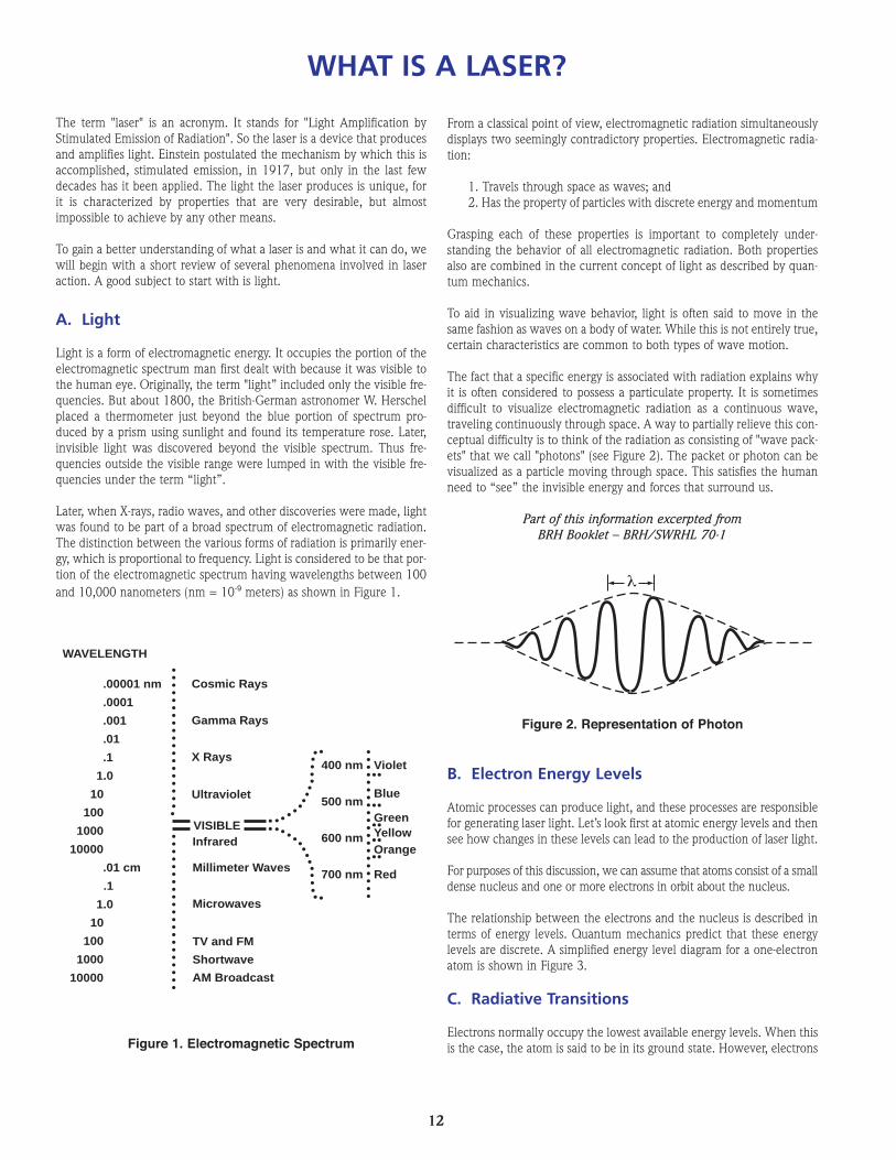
Light is a form of electromagnetic energy. It occupies the portion of theelectromagnetic spectrum man first dealt with because it was visible tothe human eye. Originally, the term "light” included only the visible fre-quencies. But about 1800, the British-German astronomer W. Herschelplaced a thermometer just beyond the blue portion of spectrum pro-duced by a prism using sunlight and found its temperature rose. Later,invisible light was discovered beyond the visible spectrum. Thus fre-quencies outside the visible range were lumped in with the visible fre-quencies under the term “light”.
Later, when X-rays, radio waves, and other discoveries were made, lightwas found to be part of a broad spectrum of electromagnetic radiation.The distinction between the various forms of radiation is primarily ener-gy, which is proportional to frequency. Light is considered to be that por-tion of the electromagnetic spectrum having wavelengths between 100and 10,000 nanometers (nm = 10-9 meters) as shown in Figure 1.
From a classical point of view, electromagnetic radiation simultaneouslydisplays two seemingly contradictory properties. Electromagnetic radia-tion:
1. Travels through space as waves; and2. Has the property of particles with discrete energy and momentum
Grasping each of these properties is important to completely under-standing the behavior of all electromagnetic radiation. Both propertiesalso are combined in the current concept of light as described by quan-tum mechanics.
To aid in visualizing wave behavior, light is often said to move in thesame fashion as waves on a body of water. While this is not entirely true,certain characteristics are common to both types of wave motion.
The fact that a specific energy is associated with radiation explains whyit is often considered to possess a particulate property. It is sometimesdifficult to visualize electromagnetic radiation as a continuous wave,traveling continuously through space. A way to partially relieve this con-ceptual difficulty is to think of the radiation as consisting of "wave pack-ets" that we call "photons" (see Figure 2). The packet or photon can bevisualized as a particle moving through space. This satisfies the humanneed to “see” the invisible energy and forces that surround us.
Part of this information excerpted fromBRH Booklet – BRH/SWRHL 70-1
B. Electron Energy Levels
Atomic processes can produce light, and these processes are responsiblefor generating laser light. Let’s look first at atomic energy levels and thensee how changes in these levels can lead to the production of laser light.
For purposes of this discussion, we can assume that atoms consist of a smalldense nucleus and one or more electrons in orbit about the nucleus.
The relationship between the electrons and the nucleus is described interms of energy levels. Quantum mechanics predict that these energylevels are discrete. A simplified energy level diagram for a one-electronatom is shown in Figure 3.
C. Radiative Transitions
Electrons normally occupy the lowest available energy levels. When thisis the case, the atom is said to be in its ground state. However, electrons
λ
Figure 1. Electromagnetic Spectrum
Figure 2. Representation of Photon

13
themselves by emitting photons of visible light. Note that in both ofthese examples electrons may be excited to any one of several ener-gy levels. The photons released in a de-excitation may have any ofthese frequencies. If enough different frequencies are present in thedistribution, the emission may appear to the eye as "white" light.
Let us look at the third, and probably the least familiar type of radiativetransition.
3. Stimulated Emission. In 1917 Einstein postulated that a photonreleased from an excited atom could interact with a second similar-ly excited atom and trigger it to release a photon. The photonreleased by the second atom would be identical in frequency, ener-gy, direction, and phase with the triggering photon. The original trig-gering photon would continue on its way, unchanged. Where therewas one, now there are two. This is illustrated in Figure 4. Thesetwo photons could then proceed to trigger more atoms throughstimulated emission.
If a medium such as a gas contains many excited atoms and de-exci-tation occurs only by spontaneous emission, the light output will berandom and approximately equal in all directions as shown in Figure5A. The process of stimulated emission however can amplify thenumber of photons traveling in a particular direction. This generatesa photon cascade as illustrated in Figure 5B. Placing mirrors at theend of an optical cavity will establish a preferred direction of photontravel. Photons not “normal” (perpendicular) to the mirrors willescape. Thus, the number of photons traveling along the axis of thetwo mirrors increases greatly and light amplification by stimulatedemission of radiation occurs.
can occupy higher energy levels, leaving some of the lower levels vacant.Electrons move from one energy level to another by absorbing or emit-ting energy. One way that an atom can change its energy state is throughwhat is called a radiative transition.
There are three types of radiative transitions. Two of these, absorptionand spontaneous emission, are quite familiar. But the third, stimulatedemission, is relatively unfamiliar and forms the basis for laser action.Each form of transition is described as follows:
1. Absorption. Electrons can absorb energy from a variety of externalsources, two of which are highly important. The first of these is acomplete transfer of energy from a photon to an orbiting electron.The increase in the energy of the electron causes it to "jump" to ahigher energy level; the atom is then said to be in an "excited" state.It is important to note that an electron accepts only the preciseamount of energy that will move it from one allowable energy levelto another. Hence, only photons of the energy or wavelength accept-able to the electron will be absorbed.
The second means often used to excite electrons is an electrical dis-charge. In this technique energy is supplied by collisions with otherelectrons accelerated by the electric field. The result of either typeof excitation is that through the absorption of energy, an electron isplaced in a higher energy level than it had at rest. The atom that itorbits is also said to be excited.
2. Spontaneous Emission. Atomic structures tend to exist in the low-est energy state possible. An excited electron in a higher energylevel will therefore attempt to "de-excite" itself in any of severalways. Some of the energy may be converted to heat. Another meansof de-excitation is the spontaneous emission of a photon. The pho-ton released by an electron will have a total energy exactly equal tothe difference between the excited and lower energy levels. Thisrelease of a photon is called spontaneous emission. One example ofspontaneous emission (and absorption) can be seen in phosphores-cent materials. The atoms are excited by photons of energy from thesun or a manmade light. In dark conditions they de-excite them-selves by spontaneously emitting photons of visible light.
A second example is the common neon sign. Atoms of neon areexcited by an electrical discharge through the tube. They de-excite
10.1 eV
13.6 eV
IonizedState
First ExcitedState
GroundState
En
erg
y
Figure 3. Typical Energy Level Diagram
Figure 4. Photon Multiplication by Stimulated Emission
A. B.
Figure 5. Photon Cascade

14
D. Population Inversion
The process of stimulated emission will not produce a very efficientamplification of light unless a condition called "population inversion"occurs. If only two of several million atoms are in excited state, thechances of stimulated emission occurring are extremely small. Thegreater the percentage of atoms in an excited state, the greater the prob-ability of stimulated emission. In the normal state of matter, most elec-trons reside in the ground or lowest energy levels, leaving the upper lev-els somewhat depopulated. When electrons are excited and fill theseupper levels so more atoms are excited than not excited, the populationis considered inverted. This is illustrated in Figure 6.
How Does The Laser Operate?
Now that we have discussed some of the phenomena, let’s see how alaser is constructed and how it operates. Three components are neces-sary: (1) An active lasing medium, (2) An input energy source (calledthe "pump"), and (3) An optical cavity.
1. The Lasing Medium. Lasers can be classified according to the stateof their lasing material (“media”). Four common classifications oflasers are presently recognized.
A. Solid State lasers employ a lasing material distributed in a solidmatrix. One example is the ruby laser, which uses a preciseamount of chromium impurity distributed uniformly in a rod ofcrystalline aluminum oxide. The output of the ruby is primarilyat a wavelength of 694.3 nm, which is deep red in color.
B. Gas lasers use a gas or a mixture of gases inside a glass tube.Common gas lasers include the Helium-Neon laser with a pri-mary output of 632.8 nm and the CO2 laser, with output in theinfrared, blue, and green regions. Even water vapor can bemade to yield a laser output in the infrared.
C. The lasing medium for Liquid lasers is usually a complex organ-ic dye dissolved in an organic liquid. The most striking featureof liquid lasers is their "tunability". Proper choice of the dye andits concentration allows light production at any wavelength inor near the visible spectrum.
D. Semiconductor lasers consist of two layers of semiconductormaterial sandwiched together. One material consists of an ele-ment with a surplus of electrons, the other with an electrondeficit. Two outstanding characteristics of the semiconductorlaser are its high efficiency and small size. Typical semiconduc-tor lasers produce light in the blue, red and infrared regions.
2. Pumping Methods. Laser action can occur only when a populationinversion has been established in the lasing medium. This can beestablished by pumping energy into the lasing medium. Severalpumping methods are commonly used. Optical pumping isemployed in solid state and liquid lasers. A bright source of light isfocused on the lasing medium. Light photons with the correct ener-gy are absorbed by electrons in the lasing material, making it jumpto a higher level. Xenon flashtubes similar to but more powerfulthan strobe lights used in photography are commonly used as opti-cal pumps for solid state lasers. Liquid lasers are usually pumped bya beam from a solid-state gas laser.
Gas lasers utilize electron collision pumping. An electrical dischargeis sent through the gas-filled tube. Electrons in the discharge loseenergy through collisions with gas atoms or molecules. Atoms ormolecules that receive the energy are excited. Electron collisionpumping can be performed continuously to provide a continuousoutput.
Semiconductor lasers are electrically pumped. An electrical currentis passed through the material layers which contain the regions ofelectron surplus and deficit. When the electrons recombine with theareas containing a deficit or “hole”, spontaneous emission of a pho-ton occurs as the electron drops to a lower energy level.
3. Optical Cavities. Once the lasing medium has been pumped toachieve a population inversion lasing action may begin. If no controlwere placed over the direction of photon movement, photon beamswould be produced in all directions. This is called super-radiant las-ing.
The direction of beam travel can be controlled by placing the lasingmedium in an optical cavity formed by two reflectors or mirrors fac-ing each other along a central axis (Figure 7). Photon beams pro-duced along the cavity axis are reflected 180º at each mirror, andtravel once more through the lasing medium causing more stimu-lated emission. Thus, the beam grows in magnitude with each passthrough the lasing medium.
Since the mirrors are not 100 percent reflective, some photons arelost by transmission through the mirrors with each passage back andforth. If pumping is continuous, a state of equilibrium is reachedbetween the number of photons produced by atoms raised to the
NormalPopulation Distribution
InvertedPopulation Distribution
E2
E1
E2
E1
E0E0
Figure 6. Illustration of Population Inversion
Figure 7. Optical Cavities

15
nique. Gas lasers may use mirrors as seals for the ends of the gastube or may utilize exterior mirrors. In the latter case, the tubes useend windows of glass or quartz set at Brewster's angle and the out-put is polarized light.
4. The Ruby Laser. The first laser successfully operated was a RubyLaser, constructed and operated by Dr. T. H. Maiman in 1960. Rubyis a crystal form of aluminum oxide with chromium about 0.05% byweight as an impurity. The chromium gives the ruby its red colorand is responsible for the lasing. Chromium exhibits a 3-level ener-gy system, as represented in Figure 9.
In a ruby laser, the electrons of chromium atoms are pumped to anexcited energy level by means of a xenon flashlamp placed besideor around the ruby rod. The chromium electrons absorb photons ina band centered around 545.1 nm and are raised from their groundlevel to excited level E2. From here, they drop almost immediatelyto level E3 by means of a phonon (radiation-less) transition. Thesmall amount of energy lost here is through heat and vibration. Theelectrons will reside in level E3 for a considerable length of time —much less than a second — but for an electron that is relatively longtime. Thus, since the flashlamp operates in a period of microsec-onds, a population inversion can be achieved.
The excited atoms begin to de-excite spontaneously, dropping fromlevel E3 to E1, and since a population inversion is in effect, stimu-lated emission can begin. In any lasing medium, stimulated emis-sion may occur in all directions, and no particular direction of trav-el (propagation) is favored. As stated earlier, to gain control of theemission direction and increase the amount of energy within thepulse, the lasing medium is placed inside an optical cavity. Photonsnot emitted along the axis of the cavity will pass out of the systemand be lost. But if a photon cascade is aligned with the cavity axis,it will encounter one of the mirrors and be reflected back uponitself, pass once more through the lasing medium, and then triggermore excited atoms to undergo stimulated emissions. The pulsethus grows in size, and on each encounter with the less reflectivemirror part of it emerges from the laser as high intensity coherentlight.
The pulse from a typical ruby laser lasts only a few microseconds,since pumping is not continuous. The flashlamp gets its energy froma charge stored in capacitor banks, and once the lamp has flashed,the capacitors must be recharged. Pumping occurs over a few hun-dred microseconds and continues as long as the flashlamp is dis-charging
545.1 nm
694.3 nm
Photon Transition
Phonon Transition
En
erg
y
E2
E3
E1
excited state and the number of photons emitted and lost. This gen-erates a continuous laser output and is usually achieved with low tomedium power input levels. Higher power inputs are generally pro-duced in the form of a pulse, and the output is also in pulse form.One of the mirrors in the system is usually made more transparentthan the other and the output, pulsed or continuous, is sent throughthat mirror.
Q switching (or Q-spoiling) is used to produce an exceptionally high-power output pulse. The term "Q" is derived from the more familiarQ of electrical devices. The Q is a numerical index of the resonantcavity’s ability to store energy at the output frequency. The higherthe Q, the more effective the power concentration at the resonantfrequency. Q-switching in lasers refers to the method of operationin which power is concentrated into a short burst of coherent radi-ation. A Q-switch is a device that interrupts the optical cavity for ashort time during pumping. A schematic of a Q-switched solid-statelaser is shown in Figure 8.
Lasing action normally begins as soon as a population inversion isachieved and continues as long as pumping action maintains theinversion. The Q-switch interrupts the optical cavity and reduceslosses due to lasing until pumping can achieve a greater populationinversion (say 70% to 80%). The Q-switch then suddenly restoresthe cavity and the resulting pulse is much shorter and more power-ful than would normally be achieved.
One example of a Q-switch is the Pockel's cell, made of a crystal ofammonium or potassium dihydrogen phosphate (ADP or KDP) sand-wiched between two crossed polarizers. In its de-energized state,the crystal will not affect polarized light. But when an electric fieldis applied across the crystal, the plane of polarization of the incidentlight is rotated by 90º, allowing it to pass the second crossed polar-izer. This completes the optical cavity and results in a giant pulse.
Reflectors can consist of plane mirrors, curved mirrors, or prisms, asshown in Figures 7 and 8. The mirror coating can be silver if laseroutput power is low, but higher power may require dichroic mate-rial. A dichroic material is a crystalline substance in which two pre-ferred states of light polarization are propagated with different veloc-ities, and more importantly, with different absorption. By appropri-ate choice of material and thickness, the light impinging on thedichroic coating may be either totally absorbed or totally reflected.The first ruby lasers were constructed with the crystal ends polishedoptically flat and silvered. Semiconductor lasers use a similar tech-
Figure 9. Energy Levels of Chromium
A. PULSED RUBY
B. Q - SWITCHED RUBY
Time
Time
Ou
tpu
t E
ne
rgy
Ou
tpu
t E
ne
rgy
Figure 8. Q-Switch and Pulse Output Diagram

16
5. The HeNe Laser. The helium-neon laser was developed in 1961 byAli Javan and proved to be the forerunner of a whole family of gaslasers. Since gas lasers are all quite similar in construction andbehavior, we shall discuss the He-Ne laser as representative of thegroup.
The lasing medium in the He-Ne laser is a mixture of about 85%helium and 15% neon, with neon providing the lasing action. Anenergy level diagram for neon is shown in Figure 10.
The four-level system of a gas laser differs from the three-level sys-tem of chromium in that the emission of a photon does not returnthe atom to a ground level. Transitions from level E3 to E4 and E4to E1 are accomplished through phonon transitions in which ener-gy is transferred mainly through heat.
Pumping neon to an excited state is not accomplished directly bythe energy source. Rather, indirect pumping is accomplished byexciting atoms of helium, which then transfer energy to the newatoms by way of electron collision. These two gases are pickedbecause they have electron excitation levels that are almost identi-cal, thus facilitating the necessary energy transfer. Additionally, in
Photon Transition
Phonon Transition
Phonon Transition
E2
E3
E1
E4
Figure 10. Energy Levels of Neon
the mixture of gases used, a population inversion in helium is notrequired in order to obtain a population inversion in neon. A morecomplete energy level scheme for He-Ne is depicted in Figure 11.
The HeNe gas mixture is contained in a sealed tube. Excitation ofthe helium is accomplished by discharging electricity through thetube, similar to a neon sign. The mirrors may be enclosed within thetube or may form the end caps of the tube containing the HeNe mix-ture. This is a solid geometrical configuration and results in a stablelight output.
Some specialized high performance applications require externallymounted mirrors and a delicate alignment procedure. When this isdone, the ends of the laser tube are made of Pyrex or quartz set ata Brewster's angle to the axis of the laser, and the output is polar-ized light.
6. Other Lasers. Other lasers operate in similar but more complicatedways. Changes in molecular energy levels may be used rather thanchanges in electron energy levels, but output is still obtainedthrough the stimulated emission of radiation.
Collision
Collision
HELIUM NEONE
ne
rgy
(H) E2
(H) E2' (Ne) E2'3390 nm
1150 nm
632.8 nm(Ne) E2
E3
E3'
E1
E4
Figure 11. Energy Levels of Gas Laser (Detail)

17
Low-cost IFO Helium-Neon (HeNe) lasers have been developed specifi-cally for educational purposes. Although it is not necessary to under-stand the theory of laser operation to perform most of the experimentsin this manual, the principles of operation described below are interest-ing applications of electronics, optics and quantum mechanics.
General Characteristics of Laser Light
Laser light is quite different from most forms of natural light. The keydifferences are:
1. Brightness - lasers have high energy concentration
2. Monochromaticity - lasers have a single color
3. Collimation - laser beams have narrow divergence
4. Coherence in time and space – laser light travels in synchronized waves.
To understand why these aspects of laser light are different, let’s seehow a laser works.
General Theory of Operation
The IFO HeNe laser is a long tube (glass or steel) filled with a mixtureof helium and neon gases under low pressure. A solid-state power sup-ply converts 110 volts AC into 1,100 volts DC. This high voltage isapplied to a set of electrodes in the laser tube setting up a strong elec-tric field. Under the influence of this field, the gases are activated and abeam of intense red light is emitted from the front of the laser. The light
is monochromatic with a wavelength of 632.8 x 10⁻⁹ m (6328Å or632.8 nanometers) and has other characteristics associated with laserlight.
The Plasma Tube
The plasma tube consists of a long capillary tube (1mm diameter) sur-rounded by a hermetically sealed (glass or steel) outer tube. The laseraction that produces the beam occurs in the central capillary tube as thehigh voltage DC is applied to a mixture of gases (approximately 85%helium and 15% neon) that are at a pressure of about 1/300 of anatmosphere. As electric energy is applied, the electrons of each gas atomrespond by changing their orbits from the normal ground level configu-ration to the larger or more complex orbits that are associated withhigher energy levels.
After a short time in an energized state, the electrons spontaneouslyrevert to their original ground state conditions, giving off their recentlyacquired energy as photons of light. They are emitted in many differentdirections, making the entire laser tube glow with the characteristicblue color of helium and the red color of neon.
Some photons are emitted along the axis of the capillary tube wherethey encounter other energized atoms. Each such encounter stimulatesthe gas atoms to produce additional photons that join the original one— like a snowball rolling down a snow-covered hill, growing larger andgaining energy as it travels. The phenomenon is called stimulated emis-sion of radiation. The stimulated emission results in a combined waveof increasing amplitude.
Upon reaching the end of the laser tube, the wave encounters a mirrorthat sends it back through the tube to stimulate more energized atoms,
THEORY OF IFO HENE LASER OPERATION
Laser Disassembled to Show Major Components

18
and increase its amplitude by a factor of 1.02 with each pass. With a flatmirror at each end of the laser tube, perfectly aligned waves of highamplitude are generated in a very short time. The waves are coherent intime because only those with an integral number of half wavelengthsfrom mirror to mirror can sustain oscillation. The situation is similar tothe standing waves in a jump rope.
To produce an external laser beam the mirror at the front of the lasertube is a partial reflector, which reflects 99% of the light and transmitsapproximately 1%. The mirror at the back of the laser tube has a higherreflectivity and reflects about 99.9% of the light while transmitting lessthan 0.1%.
Neon radiates several different wavelengths of light as its electrons fallfrom higher energy levels to the ground state. When the orbital elec-trons fall from the 3s2 to the 2p4 level, they produce some of thestrongest radiation in the visible light range (6328Å)
During the manufacturing process, coatings on the two mirrors are care-fully adjusted so the laser will resonate at the 6328Å emission, andexclude other radiation produced by the neon gas.
IFO lasers use a "semi-confocal" mirror arrangement. This consists of aflat mirror at the back of the laser tube, and a concave mirror at the frontwhere the beam comes out. Although a greater power output can beachieved with two flat mirrors (or long radius curved mirrors), they arevery difficult to align. It’s even more difficult to maintain their alignmentwhen the laser is subjected to minor mechanical stresses during opera-tion. With the semi-confocal arrangement, some power is sacrificed, butthe laser is so stable that it can withstand the vibration and stress thatoccurs in a typical student laboratory. Furthermore, the curvature of thefront mirror is calculated to focus the beam at the surface of the distantflat mirror. This curve/flat arrangement produces a laser beam that iscone shaped between the mirrors. The narrow point of the cone is at the
flat end, and the wide point is diverging at the curved end. To compen-sate for this divergence, an additional converging lens surface is placedon the laser output mirror to produce a beam whose edges are very closeto parallel.
The internal geometry of individual laser tubes causes the beam tovibrate more strongly in one particular plane. This non-symmetrical dis-tribution causes the beam to be elliptically polarized. Sometimes a sec-ondary beam is also polarized at right angles to the favored direction ofvibration. In a short laser tube the output beam is polarized at any giveninstant, and then this plane of polarization appears to shift between twofavored directions at right angles to each other in an unpredictable fash-ion. You can observe this interesting effect by passing the laser beamthrough a polarizing filter to see the changes in beam intensity (# 45-655).
The capillary tube in which the laser action occurs is surrounded by asecond tube about one inch in diameter. This outer tube has two pur-poses:
1) It supports the inner capillary tube and the two end mirrors ina rigid permanent alignment.
2) It provides a large reservoir of neon gas that replenishes the sup-ply in the laser cavity as it is slowly absorbed by the cathodeduring laser operation.
Helium gas is included in the laser because it enhances the output of theneon gas by as much as 200 times. As helium atoms are energized byhigh-voltage direct current, they collide with nearby neon atoms in avery efficient energy transfer process. Although neon gas alone will pro-vide laser action, the output is about 200 times as great when heliumand neon are mixed in proportions of about 6 to 1 (i.e. about 85% heli-um, 15% neon).
Capillary of Plasma Tube
Rear Mirror99.9% Reflective
Front Mirror99.0% Reflective
1.0% of beamemerges

19
The DC Power Supply
The DC power supply receives 110 volts AC from a standard wall out-let and produces an initial DC voltage of 2000 volts. To do this, a trans-former steps up the 110 volts to 630 volts AC. A 630-volt AC signal haspeak voltage excursions of about 900 volts positive and 900 volts nega-tive. Solid-state rectifiers act upon the positive and negative excursions
of the transformer output separately to produce two independent out-puts of 900 volts. These voltages are then added in series using a volt-age multiplier circuit to produce a combined output of approximately1800 volts. This is reduced to the required 1,100 volts with the aid ofa string of ballast resistors. To start the initial laser action and ionize thegas in the tube, a separate circuit provides a pulse of about 2,000 voltsthat is automatically removed once the laser action starts.
NOTES:

20
Wavelength
IFO helium-neon lasers emit orange-red light at a wavelength of 632.8nanometers (10-9 meters). The light is nearly monochromatic — a sin-gle color. HeNe lasers can also produce other colors, including orange,yellow, and green.
Procedure
Find a source of white light (which contains all visible colors) — per-haps the sun or an incandescent flashlight. Form a narrow beam by pass-ing the rays between two razor blades, and then direct the beamthrough a prism. A spectrum of colors will appear. Do the same with aHeNe laser beam. Since the beam has no other component wavelengthsexcept red, the laser light cannot be divided into colors.
Discussion
In practice most lasers are not completely monochromatic. A trulymonochromatic laser (a single frequency laser) produces only one wave-length. IFO lasers produce several closely related wavelength frequen-cies (axial or longitudinal modes) spaced about 500 MHz apart. Theseaxial modes are spaced within a bandwidth roughly 1.5 GHz wide.
Absorption of Light (white light)
Color filters absorb certain wavelengths, while allowing light of otherwavelengths to pass relatively unaffected.
Procedure
Hold filters of various colors in front of your eyes and view objects in theroom (not laser beams).
Discussion
Notice that objects appear dark or black (absence of light) when theircolor has been absorbed. During the absorption process, the light ener-gy of the absorbed wavelengths is changed to heat or mechanical ener-gy inside the filter.
Additional Exercises
Try to determine the percentage of blue, green, yellow, orange and redlight that passes through various color filters. Compare with the data inthe figure at right.
Absorption of Light (laser light)
Certain types of filters strongly absorb the red light from helium-neonlasers.
Procedure
Use a plano-convex lens to spread out the beam of a neon laser to a cir-cle an inch or more in diameter. Hold various color filters in front of youreyes and view the beam. Select a filter that best absorbs the red light ofthe laser.
EXPERIMENT 1. COLOR
WAVELENGTHnanometers
YELLOW
GREEN
BLUE
PE
RC
EN
T T
RA
NS
MIS
SIO
N
7006005004000
25
50
75
100
RED
7006005004000
25
50
75
100
7006005004000
25
50
75
100
7006005004000
25
50
75
100
1

21
Discussion
Special green filters used on laser safety goggles reduce the observedintensity of helium-neon laser light more than a thousand times.
A green pilot lamp on the laser helps a person wearing laser safety gog-gles find the ON/OFF switch in very dim lighting. The safety goggles donot absorb the green pilot lamp light. Safety goggles are generally notrequired for use with visible Class II lasers. The beam has low powerand the normal human eye blink reflex provides adequate protection.Lasers at higher power levels (IIIa or above) pose an eye hazard andshould be operated with caution and adequate safety procedures.
Coefficient of Absorption
The thicker a filter, the greater its absorption.
Procedure
Find some uniformly colored glass of various thicknesses. Shine a laserbeam through each and record the power output using a photometer.On a graph, plot the power output versus the thickness.
Discussion
The power output should vary in an exponential manner using the for-mula:
For details refer to Beer-Lambert Law.
A laser tube is very much like a color filter in reverse. While a green orblue filter greatly attenuates (reduces) the red light of a laser, neon gasinside the laser tube amplifies red light. The entire laser tube is built asa very selective amplifier tuned to red light at the 632.8 nanometerswavelength. Generally, the longer the laser tube, the brighter the beamwill be.
Color Signal and Noise
Using inexpensive color filters, it is relatively easy to separate red laserlight from other wavelengths of "white" light.
Procedure
Find a color filter that transmits a high percentage of red light, but verylittle white light.
Discussion
Consider the laser scanners used by supermarket cashiers to decode barcode symbols on merchandise packages. After the scanning beam cross-es the symbol, the reflected light must find its way back into the scan-ner where it can be converted to electrical energy and then into a digi-tal signal for input into a computer. Only a tiny portion of the originallaser beam gets back to the photodetector. When it does, it must beclearly separated from room light. Actually, very inexpensive red colorfilters are commonly used. They allow 90% or more of the laser light topass, while blocking 90% or more of the background white light. To thedetector, the red light is bright and the background dark. For more crit-ical applications, narrow bandwidth filters provide an even greater sep-aration of signal and noise.
xkveI −0I =

22
EXPERIMENT 2. OPHTHALMOLOGY
Overview
When an enlarged laser beam is aimed at a wall or at a piece of whitepaper, the illuminated area appears to have many small spots or grains.This granular appearance is caused by a complex interference patternproduced by the coherent light as the lens of our eye focuses it upon theretina. This phenomenon may be used to diagnose certain eye defectsand illustrate how these defects can be corrected with appropriate eye-glasses or contact lenses.
Procedure
A. In a room with subdued lighting, aim the laser beam at a piece ofwhite paper two or three meters away. Expand the laser beam usingthe +15 mm lens supplied with the Optics Education Kit.
B. Observe the illuminated area and notice the many small dots orgrains that appear. Move your head very slowly from side to sidewhile observing the spot. If your eyes are normal or you are far-sighted, the small spots will appear to move in the same direction asyour head. If you are nearsighted, the spots will appear to move ina direction opposite from that of your head movement. In near-sighted persons, the eye tends to focus the pattern a short distancein front of the retina. Therefore, the parallax caused by the head
movement results in an apparent motion of the spots in the oppositedirection.
C. You can demonstrate parallax by holding your fingers apart and plac-ing them a few inches in front of your eyes while looking at anobject on a distant wall. When you move your head from side toside while looking at the distant object (which represents the illu-minated area), your fingers (which represent the granular interfer-ence pattern) will appear to move in the opposite direction.
D. Simulate myopia (nearsightedness) by holding a long focal lengthlens in front of your eye (part # 45-654 - focal length 70 mm orgreater). Observe the movement of the granulated spots as yourhead moves from side to side, and then record the results.
E. Simulate hyperopia (farsightedness) by observing the illuminatedarea on the wall through the -46 mm lens. Observe the exaggerat-ed movement of the granulations as they move in the same direc-tion as your head from side to side.
F. If you normally wear eyeglasses or contact lenses, check your eyesin the manner described above with and without the correctivelenses (if convenient), then record your results.

23
EXPERIMENT 3. POLARIZATION EFFECTS
1586.eps
Polarizing Filters
Polarizing filters have a crystalline structure that allows waves vibratingin line with the crystals to pass, while blocking those vibrating perpen-dicular to the crystal structure.
Polarization (white light)
All waves, including light waves, possess one of two different types ofmotion. Sound waves are compressional motion (like compressing, thenreleasing a spring). Light waves, however, are transverse. To visualizetransverse waves, imagine holding one end of a 10-foot-long rope in onehand. The other end of the rope is fastened to a wall, and you are pullingit tight, so it extends in a horizontal line. Now move that handup/down, right/left and circular in random patterns. With thesemotions you are creating a visual model of a transverse light wave.Energy, or light, begins at your hand and ends up at the wall. All ener-gy or waves that you created in the rope are unpolarized because thereis no defined pattern or motion. Sunlight is unpolarized, as is light frommost light sources except lasers.
Conversely, a linearly polarized wave travels in a known and non-vary-ing pattern, as if you were to move the rope only up/down. Unpolarizedwaves can be filtered/transformed into polarized waves if we use spe-cial materials with slots or gratings in them. Imagine the rope passingthrough a grating with only vertical slots, as shown above. The slot pre-vents sideways motion, but freely allows the vertical components ofvibration to pass.
Placing a second vertical grating behind, and aligned with, the first willstill allow the vibrations to pass through both sets of slots freely.However, if we turn the second grating to a horizontal position, none ofthe vertical light/waves exiting the first grating will pass through or betransmitted by the second grating.
Procedure
View an eye safe white light source through a single 50 x 50 mm polar-izing filter (# 45-655). An incandescent bulb is a good candidate. Rotatethe filter 360º and note any changes in brightness.
Discussion
With a single polarizing filter we notice a slight light loss in all orienta-tions. Optical power meters and the human eye can’t detect changes inpolarization unless a polarizing element is used. A light source that does-n’t restrict which directions the waves vibrate has approximately thesame number of waves vibrating in each orientation.
Procedure
Place a second polarizing filter behind the first. Rotate the second filterand note the changes in light intensity.
Discussion
With a single polarizing filter the light intensity was the same in all ori-entations. After passing through the filter light waves are oriented so
their wave crests and troughs are roughly in the same orientation as thecrystals of the filter. When we place a second filter behind the first, lightwill pass if the crystals in both filters are aligned. But if the crystals ofthe second filter are perpendicular to the first, very little light will passthrough.
Laser Polarization Effects
Many lasers exhibit changes in polarization orientation randomly overtime.
Procedure
Turn on a laser from a cold start. Place a single polarizing filter in frontof the laser and monitor the beam power using a photometer. Keep arecord of the power readings every 10 seconds for 20 readings. Are thechanges random or regular?
Discussion
Some lasers contain a special optical element called a Brewster windowthat restricts polarization to one plane. The light output of these lasersis considered linearly polarized. Lasers without a Brewster window emitlight with two polarization components always at right angles to eachother. Especially during laser warm-up, the power of one componentwill increase while that of its counterpart will decrease. These changesoccur randomly, seconds to minutes apart. The polarization selectivityis determined in large part by the mirror coatings. The changes occur asa direct result of small changes in mirror spacing as the laser tube swellsin size while heating up. These distance changes affect the longitudinalmodes under the Doppler curve. (Note: if the laser is linearly polarized,no changes will occur. Only the light from ordinary lasers is randomlypolarized.)

24
EXPERIMENT 4. MEASURING THE INDEX OFREFRACTION OF GLASS
Laser Beam
Beam Spreader
Beam Spreader
Normal
Laser
Laser
ι
γ
GlassPrism
GraphPaperOpen
AVOID EXPOSURE
LASER RADIATION IS EMITTED
FROM THIS APERTURE.
1590.eps
Overview
When light travels from one transparent medium to another, we usual-ly observe a change of speed at the interface between the two media.This phenomenon also may be demonstrated as a fine laser beam trav-els from air into glass. If the angle between the laser beam and the glasssurface is less than 90°, bending, or refraction, of the light occurs at thepoint where the speed changes. The amount of bending depends on theangle of entry and the index of refraction of glass, which we will meas-ure in this experiment.
Procedure
A. Tape a sheet of graph paper over the surface of a vertical mount.Magnetically attach a rectangular glass prism to the mount. Placethe beam spreader over the laser aperture so the laser beam isspread out over both the prism and the face of its mounting panel.
B. Rotate the glass so the laser beam enters the edge at an angle ofabout 30° and emerges from the opposite side.
C. On the graph paper behind the glass plate, carefully mark the point
where the laser beam enters the glass and the point where itemerges.
D. Measure the angle of incidence formed by the incoming laser beamand the normal to the surface of the glass.
E. Measure the angle of refraction formed by the refracted beam insidethe glass and the normal to the surface.
F. Calculate the index of refraction using the Snell's Law relationship:
G. Repeat the procedure above while holding the glass so the angle ofincidence changes for each trial. Note the effect on the size of theangle of refraction as the angle of incidence is increased ordecreased. For each angle of incidence, calculate the index of refrac-tion of the glass.
γsin
sin iN =
Angles of index and refraction are formed between the laser beam and a normal drawn on paper.

25
EXPERIMENT 5. INDEX OF REFRACTION OF A PRISM
Rotate prismwhile observingdeviated beam
Angle ofDeviation
Laser
Beam
Laser
Original
Direction
Deviated
Beam
A
1591.eps
Overview
When a laser beam passes through a triangular prism, the beam isrefracted twice and emerges at an angle that deviates from its originaldirection of travel. The deviation depends on the laser beam’s incidentangle, and the prism’s index of refraction and apex angle. By rotating theprism, the minimum angle of deviation for the particular prism can bedetermined. This is where the laser beam angle of incidence equals theexit angle of refraction, causing the minimum deviation from the origi-nal direction of travel. Under this condition the calculation for the indexof refraction for the prism is greatly simplified. By measuring the apexangle of the prism (A) and the minimum angle of deviation (q), the indexof refraction of the prism may be calculated:
Procedure
A. Lay the prism (# 45-756) on its side and aim the laser beam into itas shown in the Figure.
B. Prism # 45-726 is an equilateral triangle so the apex angle is 60degrees. If using a different prism measure and record the apexangle. Slowly rotate the prism while observing the amount of devi-ation between the emerging laser beam and the original beam direc-tion. Record the value of the minimum angle of deviation that youobserved while rotating the prism.
C. Substitute the measured values of the apex angle and the minimumangle of deviation in the formula given above to calculate the indexof refraction of the prism.
NOTE: To obtain greater precision in determining the minimumangle of deviation using a laser beam, we suggest the following pro-cedure:
Aim the laser beam across a room and mark the spot where it strikesthe wall. Place the triangular prism on its side in front of the laserbeam and rotate it slowly while watching the deviation of the beamon the distant wall. Rotate the prism back and forth until the beamdeflection from the original direction is at a minimum. Using thislong distance technique, we can easily and precisely calculate themagnitude of the minimum angle of deviation by measuring the dis-tances and applying simple trigonometry.
( )A
An
2/1sin
2/1sin θ+=
Long distance techniques permit precise determinations of index of refraction using a laser beam.

26
EXPERIMENT 6. BEAM DIVERGENCE ANDCONVERGENCE BY LENSES
+80mm+7mmPlano-ConvexLens
Collimated beam
8 cm
Laser
1592.eps
Overview
Because a laser beam is so narrow and intense, it may be used with lens-es to reproduce most of the textbook diagrams in geometrical optics. Inthis experiment the characteristics of lenses supplied in the OpticsEducation Kit will be investigated singly and in various combinations.
Procedure
A. Mount the plano-convex lens # 45-632 (+7mm) on the verticalMaggie carrier about two centimeters in front of the laser. Hold apiece of graph paper in front of the lens and record the diameter ofthe laser beam as you move the graph paper away from the lens atintervals of one centimeter. On a graph, plot the beam diameter inrelation to its distance from the lens. When the graph values are full,extrapolate additional graph values by extending the line to the leftuntil it reaches the coordinates where the beam diameter is zero.This point is the virtual focus of the plano-convex lens, and the dis-tance between the virtual focus and the lens is the focal length.Compare your measured value for the focal length and the nominalvalue listed on its mounting card.
B. Mount the converging lens +80 mm (part # 45-654) on a Maggiemount platform 8 cm in front of the plano-convex lens. Adjust theposition of the converging lens by moving it closer to or further fromthe plano-convex lens until a collimated beam with parallel sides isproduced. Check for parallelism of the collimated light by holding apiece of graph paper in the laser beam and moving it away from thelens as far as possible, checking the beam diameter at intervals ofone meter. Record the exact positions of the laser, the +7 mm plano-convex lens and the +80 mm converging lens when parallelism ofthe beam edges has been accomplished. This data will be useful forfuture experiments where expanded collimated light is required.
C Using a beam of expanded collimated light (step B, above) mount asecond converging lens +15 mm (part # 45-652) on the opticalbench in the laser beam. Hold a piece of graph paper in front of thelens and observe changes in beam diameter as the graph paper ismoved away from the lens. Observe that the beam converges to apoint and then diverges. The point is the principal focus of the lensand the distance between the lens and the principal focus is its focallength. Measure the focal length of this lens and compare the valueyou derived with the nominal value listed on the mounting card.
D. The focal length of a compound lens made of two simple lenses canbe predicted if we know the focal length of the first lens (ƒ1), thefocal length of the second lens (ƒ2) and the distance (d) between thetwo lenses. If known values for these parameters are substituted inthe lensmaker's formula, the combined focal length of the two lens-es may be predicted using the relationship:
If either of the two lenses is divergent (characterized by a virtualfocus), use a negative focal length for this lens when substitutingthe value in the formula. If the calculated answer comes out with anegative number for the combined focal length, it indicates that thecombined system of two lenses has a virtual rather than a real focus.Measure the combined focal length of any two lenses using the pro-cedures described above. Place the two lenses in a beam of colli-mated light, measure the distance between the two lenses, and pre-dict the combined focal length of the system. Turn on the laser andtry this, checking the accuracy of your predictions.
2121
111
ff
d
fff−+=
Galilean telescope arrangement of lenses produces enlarged collimated beam.

27
EXPERIMENT 7. FOCAULT KNIFE-EDGE TEST
Screen
+15mm
RazorBlade
+80mm+7mmPlano-ConvexLens
Laser
1593.eps
Overview
The Foucault knife-edge test is a standard technique used byastronomers to determine the quality of lenses and curved mirrors.Although this test was traditionally performed with ordinary white light,the monochromatic laser offers much greater precision. The difficultyassociated with chromatic aberration of white light tends to mask lensdefects caused by faulty grinding or by the use of poor quality glass.
Procedure
A. Mount a plano-convex lens and +80 converging lens combination infront of the laser to obtain a beam of collimated light using the pro-cedure described in Experiment 6.
B. Mount the +15 mm (part # 45-652) converging lens in the colli-mated laser beam. Observe that this lens converges the light to afine point, after which the light diverges.
C. Insert a new single-edge razor blade (part # 45-662) into the laserbeam at the crossover point as shown on the diagram. If a lens isperfect, the spot on the screen should darken uniformly as the razorblade cuts the beam. If there are any irregularities in the lens, thebeam, instead of darkening uniformly, will produce irregularlyshaped areas on the screen, some parts of which are brighter thanothers.
D. Try examining camera lenses of different quality using the Foucaultknife-edge, and then record your results.
Apparatus arrangement for testing quality of +15mm lens

28
EXPERIMENT 8. KNIFE-EDGE ANDSINGLE SLIT DIFFRACTION
Open
AVOID EXPOSURE
LASER RADIATION IS EMITTED
FROM THIS APERTURE.
1595.eps
Overview
Although it was formerly believed that light traveled in perfectly straightlines, the laser offers convincing proof that light actually bends, or is dif-fracted, around small objects. The intense monochromatic laser beameasily demonstrates this phenomenon.
Procedure
A. Knife-edge diffraction can be demonstrated by pointing the laser ata screen, such as a sheet of glossy white paper, approximately threemeters away. Slide the edge of a new razor part way into the laserbeam and observe the interference pattern on the screen. Closeobservation will show that there is no sharp shadow of the edge ofthe razor blade on the screen but instead there is a diffraction pat-tern consisting of a series of bright and dark fringes parallel to theedge of the razor blade.
B. Using the same set-up as for the knife-edge diffraction, insert a sec-ond razor blade into the other side of the laser beam so the edge dif-fraction patterns produced by the two razor blades can be seen onthe screen simultaneously. Observe the effects on the two diffractionpatterns as the two razor blades are brought closer and closertogether to form a narrow slit, and their respective diffraction pat-terns merge.
C. Observe the diffraction patterns formed by sending the laser beamthrough single slits of known width. The diffraction pattern willconsist of a wide central bright fringe with a series of less intensenarrower fringes on either side.
The spacing and wavelength of the laser are related by the formula:
Where: θ is the angle between the peak of the centralmaximum and the peak of the first bright fringeon either side.
w is the width of the single slit
D. In a darkened room, project the single-slit diffraction pattern on ascreen several meters away from the laser. Confirm the relationshipdefined by the formula in paragraph C.
w2sin
λθ =
Open
AVOID EXPOSURE
LASER RADIATION IS EMITTED
FROM THIS APERTURE.
1594.eps

29
EXPERIMENT 9. DOUBLE SLIT DIFFRACTION
25X25 25X35 25X50 50X50
25X25
25X35
50X50
25X50
1596.eps
Overview
When a laser beam passes through two equal, narrow, parallel stilts,each slit produces an identical diffraction pattern. If the slits are closeenough together, the diffraction patterns overlap and interferenceoccurs. In this experiment, we will observe double-slit diffraction andexamine the characteristic diffraction and interference patterns pro-duced as the slit widths and spacing are varied.
Procedure
A. Place the diffraction slide mosaic (# IF-508 furnished with theOptics Education Kit) in front of the laser so the beam is transmit-ted through the first of the four double slits (labeled 25u x 25u). The
distance between slits is approximately 4.5x10⁻⁵ m. Observe the dif-fraction pattern that appears on a screen one meter from the laser.At first glance, the pattern seems similar to the diffraction patternproduced by a single slit, but on closer observation, you can see sev-eral interference fringes within the diffraction pattern produced bya single slit. Use a photometer or power meter to measure the lightintensity of the interference maxima (bright fringes) in various partsof the diffraction
B. Using the same set-up as in Step A, observe the double-slit diffrac-tion pattern that is produced by the second pair of slits (marked 25u
x 35u). These slits are the same width, but their separation, d, is
approximately 5.8x10⁻⁵ m. Compare this diffraction pattern withthat obtained in Step A, referring to the original pattern if necessary.
C. Observe the diffraction pattern produced by the third pair of slits
(marked 25u x 50u). The separation, d, is approximately 7.5x10⁻⁵m.Compare this pattern with those from steps A and B.
D. Considering the findings and observations you made in steps A-C,predict the diffraction pattern of the fourth pair of slits (marked 50u
x 50u). The slit width, w, is twice that of the others, and separation,
d, is approximately 10 x 10-5 m. Use the laser to check the accura-cy of your prediction.
E. The well-known formula that relates the wave-length of light andthe spacing of interference fringe is:
Where: λ is the wavelength of light (632.8 x 10⁻⁹ m for ahelium-neon laser)d is the distance in meters between splits sin θ is the distance between two adjacentinterference fringes on the screen divided by thedistance between the diffraction slide and the screen
F. Using long distances between the laser and the screen to minimizeerror, calculate the exact distance, d, between each pair of slits onyour slide.
G. Use a different distance between the laser and the screen and repeatStep F. The results obtained for slit separation in each case should beidentical.
θλ sind=

30
EXPERIMENT 10. MULTIPLE-SLIT DIFFRACTIONUSING GRATINGS
25 lines/mm 50 lines/mm
25X25 25X35 25X50 50X50
INDUSTRIAL FIBER OPTICS P/N IF-510-RD6
100 lines/mm
1597.eps
Overview
When laser light is transmitted through a series of narrow parallel slitsspaced closely together, each slit produces a diffraction pattern that over-laps the patterns produced by the others. If the slits are evenly spaced,a pattern very similar to that of the double slits emerges, but muchbrighter. In this experiment we will investigate the diffraction and inter-ference patterns produced by three diffraction gratings. Because photo-graphic film shrinks during processing, all of the line spaces depicted inthe illustrations and instructions below should be taken as approximatevalues.
Procedure
A. Aim the laser at a screen at least three meters away. Hold the dif-fraction slide mosaic in the laser beam so the diffraction grating with25 lines/mm is in the beam. Walk close to the screen and carefullyobserve the diffraction pattern. Compare the fine detail of the brightfringes with the detail of the double-slit diffraction patterns in theprevious experiment.
B. Place the middle diffraction pattern, with 50 lines/mm, in the laserbeam and again observe the pattern carefully. Compare the spacingof fringes in this diffraction pattern with the spacing from the 25line/mm grating observed in Step A. Record your results.
C. The formula that relates wavelength of the light and spacing of slitsis identical to the one used for double slit diffraction:
Where λ is the wavelength of light (6.328 x 10⁻⁷ meter)d is the distance between adjacent slitssin θ is the distance between two adjacent fringesdivided by the distance between that diffractiongrating and the screen
Adjust the positions of the laser and the screen so they are fivemeters apart. Using the formula above, determine the distance (d)between adjacent slits on each of the three diffraction gratings.
D. Change the distance between the laser and the screen to a differentvalue and repeat Step C. If your measurements and calculationswere correct, the results should be identical to those previouslydetermined. This will provide confidence in your measurementtechniques and calculations.
θλ sin•= d

31
EXPERIMENT 11. INTERFERENCE BY MULTIPLEINTERNAL REFLECTIONS IN GLASS
Screen+80mm
Reverse patternfrom front of plate
Interference patternfrom rear of plate
Glass Plate
+7mm
Laser
1599.eps
Overview
When a laser beam passes through a flat glass plate, some of the light istransmitted and some is internally reflected in the glass. As reflectedlight is subsequently emitted from both sides of a microscope slide atintervals along the surfaces, interference occurs among the multiplebeams of coherent light. In this experiment, we shall investigate thenature of this interference.
Procedure
A. Place the plano-convex lens (+7 mm) and the converging lens +80mm (part # 45-654) in the laser beam. Adjust the distance betweenthem to make a spot about 15 cm in diameter on a glossy whitescreen approximately one meter from the laser. Place a microscopeslide so its surface makes an angle of 90° with the beam. Slightadjustments of the slide position should produce an interference pat-tern on the screen, which consists of concentric light and dark cir-cles. The dark circles are caused by destructive interference
between the waves transmitted directly through the glass and thosereflected internally. The waves reflected internally have a differentpath length and are one or more half wavelengths out of phase withthe directly transmitted waves.
B. Spectacular interference patterns may be obtained by placing themicroscope slide in the laser beam as shown in the diagram so thatit is almost parallel to the beam. This will produce two sets of inter-ference patterns: one coming from each surface of the glass plate.Observe the two patterns carefully and account for the similaritiesand differences between them.
C. Slowly rotate the plate, observing the shifts that take place in theposition of one of the patterns and in the fringes of both patterns.Record your observations, then account for them based on yourknowledge of the theory of reflection and the phase changes thattake place as light waves pass through the interfaces between airand glass.
Interference patterns produced by internal reflections emerge from rear of glassplate, and reversed patterns emerge from the front.

32
EXPERIMENT 12. LLOYD’S MIRROR
Open
AVOID EXPOSURELASER RADIATION IS EMITTED
FROM THIS APERTURE.
1600.eps
Laser
7 mm (mounted on laser)
+80mm
+80mm
L-Shape Carrier�and Microscope Slide
Overview
Lloyd’s Mirror is a classic experiment in optics first described in 1834.It is a simple technique for finding the wavelength of light using amethod that is very similar to that of Young’s Slit. This experiment isusually conducted in advanced optics courses because of difficulties inalignment when using ordinary monochromatic light. However, with alaser beam alignment is simple, and excellent quantitative results maybe obtained in a few minutes.
Procedure
A. Mount the plano-convex lens (+7 mm) in front of the laser. Mountthe converging lens (+80 mm) about 10 cm in front of the plano-convex lens. Adjust the position of the converging lens so the laserproduces the smallest possible spot on a glossy white paper screenplaced about three meters in front of the laser.
B. Mount a small L-Shaped carrier on a Maggie mount so it forms ahorizontal ledge near the center of the panel. Place a microscopeslide on this ledge and mount the whole assembly between the twolenses as shown on the diagram. Adjust the height of the horizontalglass plate so the laser beam just grazes its upper surface. Adjust theposition of the glass plate so a second spot appears on the screenabout an inch above the first. Because the laser beam is essentiallyparallel, the location of the source that produces the lower spot onthe screen is at the principle focus of the plano-convex lens. This is
located +7 mm behind the plano-convex lens, as shown on the nextdiagram. The second spot produced by the mirror comes from a vir-tual source a short distance below the actual source.
C. Calculate the distance between the actual source and the virtualsource using the relationship:
Where: d is the distance between the actual and virtual sourcesD is the distance between the two spots on the screenp is the object distanceq is the image distance
C. Carefully remove the converging lens from the apparatus set-upwithout disturbing any of the other components. Without this lens,the cones of light coming from the two sources will partially over-lap, forming an interference pattern on the screen. This pattern willconsist of alternate red and black horizontal lines (fringes) along thebottom of the illuminated area on the screen. The alternate fringesprovide evidence of constructive and destructive interference as thelight from the two sources arrives on the screen in or out of phase.
q
p
D
d=

33
Actual Source
Virtual Source
d
D
P q
D. Calculate the wavelength of the laser light using the formulas fordouble-slit diffraction given in a previous experiment. The relation-ship is:
Where: λ is the wavelength of the laser light to be foundd is the distance between the two sources (determined in the step above)sin θ is the distance between any two bright fringes or any two dark fringes on the screen divided by the distance between the screen and the source
NOTE: The distance between fringes on a screen is easily measuredby projecting the interference fringes on a white ruler that has a mil-limeter scale.
To find the distance between two bright fringes, count the totalnumber of bright fringes in a distance of 24 cm. If you find it diffi-cult to count the fringes, use a magnifying glass held near thescreen. If the first few fringes near the bottom of the illuminatedarea are irregularly spaced, use the other fringes a bit higher up onthe screen.
θλ sin•= d
Calculating the distance between two sources by measuring distances P, q and d.

34
Overview
The Michelson interferometer is a precise measuring device with manyapplications in science and industry. It consists of a partial mirror calleda beam splitter and two front surface mirrors. Before the advent oflasers, aligning these components was very difficult to achieve underordinary laboratory conditions — necessitating the use of expensive andintricate alignment apparatus. By using a laser beam however, alignmentrequires only minutes.
Procedure
A. Mount a front surface mirror on the Maggie Mount platform asshown in the diagram. To permit both horizontal and vertical adjust-ments to the mirror, use the combination vertical and L carriers asillustrated.
B. Adjust the height of the mirror so the laser beam strikes its center.Aim the mirror so the reflected laser beam returns to the front of thelaser and strikes it just above the aperture.
C. Mount the beam splitter on a vertical Maggie carrier and place it inthe laser beam at an angle of 45 degrees, as shown in the diagram.
B. Place a sheet of glossy white paper in front of the beam splitter atright angles to the laser beam. A bright red spot should appear on
EXPERIMENT 13. MICHELSON INTERFEROMETER(ELEMENTARY FORM)
Screen
Platform
First frontsurface mirror
Second frontsurface mirror
Beam Splitter
7mm Plano-ConvexLens
Top ofLaser
1602.eps
the screen due to partial reflection of the returning laser beam fromthe beam splitter.
E. Mount the second front surface mirror in the position shown in thediagram. Adjust the mirror so it reflects the laser beam back throughthe beam splitter and forms a second spot on the screen.
F. Make slight adjustments to the two mirrors so the two red spots onthe screen come together and are superimposed on each other.
G. Enlarge the size of the spot on the screen using plano-convex lens #45-632. When the spot is enlarged, you should be able to see alter-nate light and dark fringes on the screen caused by interferencebetween the reflected laser beams arriving by separate paths.
H. Blow some air along the surface of the apparatus and observe theshifting of light and dark fringes on the screen in response to theslightest movement.
I. To demonstrate how the Michelson interferometer can detect eventhe slightest movement, try holding one of the mirrors steady inyour hand instead of having it mounted on the surface. You will findit nearly impossible to keep the interference fringes stationary on thescreen, due to almost imperceptible movements of even the steadi-est hand.
Top view of platform with mirrors and beam splitter. The plano-convex lensenlarges the interference pattern on the screen.

35
1604.eps
Screen
Platform
First frontsurface mirror
Second frontsurface mirror
Beam Splitter
7mm Plano-ConvexLens
Laser
Spot must appearaway from hole
Platform
Mirror mountingtechnique forStep A
L Carrier
Mirror
1603.eps

36
EXPERIMENT 14. THIN FILM IN INTERFERENCEUSING AN AIR WEDGE
Air Wedge
Screen
Plano-Convex Lens7mm
Air Wedge
Interference patternon screen
TOP VIEW
Laser
Overview
When a thin layer of air separates two sheets of flat glass, multiple reflec-tions of light occur at the air and glass interfaces. If the thickness of theair layer is adjusted so it is _ the wavelength of the incoming light (orodd multiples of _ wavelength), none of the light will be transmitted,although both air and glass are perfectly transparent. In this experiment,the phenomenon of thin film interference will be investigated.
Procedure
A. Enlarge the laser beam by mounting plano-convex lens # 45-632(+7 mm) on the Maggie Mount platform.
B. Place a screen one or two meters away at a right angle from the pathof the expanded laser beam.
C. Hold the air wedge in front of the laser at a position lined up with
the screen as shown in the Figure. Rotate the air wedge to a 45degree angle so that the reflected part of the laser beam is projectedon the screen. You should see dark interference fringes in thereflected beam.
D. Vary the thickness of the air layer wedge by squeezing the glassplates together with your fingers in different places around the edge.Observe the changes in the pattern on the screen as you squeeze theglass. Record your observations and explain in a short paragraphwhy they occurred.
NOTE: Good views of fine interference patterns are sometimesobscured by unavoidable clutter and random interference patternsthat develop in the laser optics. To “clean” the laser output, use the+15 mm converging lens (part # 45-652) and a pinhole as a spatialfilter. The technique for arranging and adjusting such a spatial filteris described in experiment 17 of this manual.

37
EXPERIMENT 15. DIFFRACTION FROM SMALL HOLES
Laser Beam
Pinhole ofdiameter (d)
Screen is about one meterfrom pinhole
Laser
1606.eps
Overview
In principle, diffraction of a laser beam by a small hole is similar to dif-fraction by a single slit. A hole is a rotated case of the slit. The oppositeedges cause the same diffraction fringes as a slit. But the pattern is cir-cular since the edges are at a constant spacing around the circumferenceof the hole. Using the bright monochromatic light from a laser, thesecomplex well-defined patterns are easily reproduced for study and inves-tigation.
Procedure
A. Part # 45-663 contains a needle and 10 sheets of aluminum foil.Create a pinhole as follows: Layer 8 to 10 sheets of the foil on apiece of glass. Puncture the stack of aluminum with the needle andselect a pinhole from one of the middle layers. If the hole has beenmade properly, a bull’s-eye pattern will form on the screen when thelaser beam passes through the hole. A perfectly round pattern on thescreen indicates the pinhole is also perfectly round. Experiment atmaking your pinholes smaller and smaller. The smaller the pinhole,the larger the bull’s-eye.
B. Calculate the size of your pinhole by measuring the radius of theAiry disc (the central bright disc in the bull’s-eye pattern) on thescreen. Do this by using the relationship:
Where: d is the diameter of the pinholex is the radius of the Airy discL is the distance from the pinhole to the screenλ is the wavelength of the light (6.328 x 10⁻⁷ meter)
C. The spark produced by a Tesla coil can be used to make a small pin-hole. Adjust the coil to work at its slowest rate and make a series ofsmall holes by passing a piece of fresh carbon paper across the sparkgap between the Tesla coil and a grounded metal plate. Using theprocedure of Step B, measure the sizes of the pinholes and cut outand mount the better ones for future use.
Refer to a textbook on optics to learn more about the theory of the Airydisc and its practical use in astronomical observations.
xL
d2λ
=

38
EXPERIMENT 16. OBSERVING HOLOGRAMS
Open
AVOID EXPOSURE
LASER RADIATION IS EMITTED
FROM THIS APERTURE.
Laser
+7mmPlano-Convex
Lens
Beam
HolographicFilm
Scene Appears Here1607.eps
Overview
One of the most striking applications of continuous laser light is its abil-ity to make three-dimensional photographs called holograms.
We create a hologram by exposing a photographic emulsion to a scenethat is wholly illuminated with laser light. The negative is simultane-ously exposed to the reference beam that comes directly from the laser.As light from the two sources falls on the negative, an interference pat-tern is recorded. In places where the light from the two sources is inphase, constructive interference occurs, forming a bright spot. Wherethe light is out of phase, destructive interference occurs, forming a darkspot. These bright and dark areas are so close to each other on the neg-ative that they can be seen only with the aid of a high-power micro-scope.
We hope the exploratory exercises described below will motivate stu-dents to make their own holographs using laser beams and special high-resolution film. You could help to pioneer the development of hologra-phy for the future.
Procedure
A. Spread the laser beam by placing the plano- convex lens (+7 mm)over the laser aperture.
B. Place the hologram in the laser beam about one meter from thelaser. At this distance, the diameter of the beam should be approx-imately 7 cm so that it illuminates most of the hologram.
NOTE: Although students are always cautioned not to look direct-ly into the laser aperture because of possible danger to the eye, it isperfectly safe to do this when a Class II laser beam has been spreadto a diameter of seven centimeters. Spreading the beam out to a spotthis size reduces the energy concentration to less than one-thou-sandth the value of the original laser beam.
C. With the room darkened, look in the area about 20 centimeters
below the laser aperture. You should be able to see a three dimen-sional scene that was recorded on the hologram.
D. While holding the hologram stationary in the laser beam, move yourhead slowly up and down and from right to left. As your eyes viewthe objects from different angles, you should be able to see theobjects from different perspectives just as you would if there werean actual group or real objects in front of you.
E. Make a hole about one centimeter in diameter in the center of asheet of notepaper and move this over the face of the hologramwhile looking through it at the three-dimensional scene. Each por-tion of the hologram contains all the information for viewing theentire scene. There are slight differences, however, among the vari-ous portions of the hologram. Describe these differences as you viewthe scene.
F. While looking at the scene through the hologram, reach out and tryto touch various portions of the objects that you see. Notice the illu-sion of depth perception as your hand moves further away from orcloser to the various objects.
G. Holding the hologram in the laser beam, lower your head and lookat the area about 20 centimeters above the laser aperture. A secondimage should appear at this location. Describe this image and com-pare it with the first one.
H. Look at the hologram through a high-power microscope. Notice thevariations in tone that form the interference pattern.
NOTE: When looking at the hologram in ordinary light, you willnotice that there are irregularly shaped light and dark patterns on thefilm. These variations are not the actual holograph pattern thatmakes the scene you saw. They actually are the equivalent of finger-print smudges on a photographic print. On the hologram, these visi-ble tone variations consist of unwanted interference patterns causedby dust in the air and on the laser itself. These should not be con-fused with the actual hologram pattern — it is microscopic in size.

39
EXPERIMENT 17. SPATIAL FILTERING
+15mm Lens
Laser Beam
"Clean Laser Beam"
100µm Pinhole
1608.eps
Overview
The mottled appearance of an enlarged laser beam is due to unavoidablespecks of dust and minor irregularities in the laser optics. This causescomplex diffraction patterns that appear in the laser output as unwant-ed “noise”. The construction of the spatial filter described in the exper-iment helps remove clutter in the laser beam. It will also be useful forother experiments that require observing fine details in diffraction pat-terns.
The spatial filter works on the principle that a lens will focus the “clean”aspects of a laser beam to a sharp point that will barely pass through asmall pinhole. The noise and interference patterns are not focused in thesame location and are thus screened out by the pinhole.
Procedure
A. Mount a +15 mm (part # 45-652) focal length lens and pinhole onthe Maggie Mount platform as shown in the diagram. No pinholesare furnished with the Optics Education Kit. But one can be orderedthrough an optics supplier or made as follows: Part # 45-663 con-tains a needle and 10 sheets of aluminum foil. Create a pinhole byplacing 8 to 10 sheets of aluminum foil on a piece of glass. Puncturethe stack of aluminum with the needle and select a pinhole from
one of the middle layers. Use tape to attach the foil to the MaggieMount.
B. Move the pinhole carrier to a position about 15 mm from the lens,where the focal plane of the lens would be located. Check this posi-tion by turning on the laser and using the lens to focus the beam tothe smallest possible spot on the pinhole carrier. Aim the beam to apoint that is very close to the pinhole, but not on the hole itself.
C. Check that the pinhole carrier is positioned at the exact focal planeof the lens and perpendicular to the laser beam by trying a simpletrick. Slowly move the laser a short distance up and down and fromside to side, while aiming it at various portions of the lens. Observethe movements of the small red spot on the diffraction slide mosa-ic. If the carrier is at the lens focal plane, movement of the small redspot will be at a minimum. The spot may even appear to be sta-tionary.
D. When you are certain that the carrier is on the focal point of thelens, manipulate the pinhole until the laser beam passes rightthrough it and diverges on the other side. The smaller the hole used,the cleaner the beam, but it will be more difficult to make the prop-er adjustment.

40
EXPERIMENT 18. DIFFRACTION PATTERNSFROM A RULER
Laser Beam Stop
Plastic Ruler
Plano-Convex Lens+7mm
TOP VIEW
0
1
2
3
4
5
6
0
1
2
3
4
5
6
7
8
910
1112
1314
15
1609.eps
Overview
Diffraction is often demonstrated with narrow single slits, closely spaceddouble slits, and diffraction gratings. But it also can be observed in com-mon objects. An example is an ordinary plastic ruler with fine blackmarkings spaced at intervals of one millimeter or sixteenths of an inch.
Procedure
A. As shown in the diagram mount the 6-inch ruler furnished with theOptics Education Kit. The laser beam should just graze the ruler soit illuminates approximately three centimeters of the metric scale.
B. Place a screen about two meters away from the laser so the diffrac-tion pattern from the ruler can be observed. The pattern will con-sist of alternate bright and dark areas spaced at regular intervals.Small adjustments of the ruler with respect to the laser beam maybe necessary to sharpen the pattern.
C. Place a plano-convex lens in the laser beam at the end of the rulerso that fine details of the diffraction pattern can be observed on thescreen. When this has been done, move the ruler very slightlywhile watching the screen. Try to explain the causes of the diffrac-tion patterns that you observe.

41
EXPERIMENT 19. MEASURING THE CURVATUREOF THE EARTH
Overview
A laser beam in air is essentially a straight line. By using this line as a ref-erence, the curvature of the earth can be measured with a fair degree ofaccuracy.
Procedure
1. On a large frozen lake*, set up a laser and a target as far apart aspossible. A distance of at least a mile will enhance the measurementprecision.
2. Collimate the laser beam (using the procedure described inExperiment 6).
3. Aim the beam at the distant target so the distance of the beam abovethe ice at the laser is the same as the distance of the beam above theice at the target.
4. At a point midway between the laser beam and the target, measurethe height of the beam above the ice. Because of the curvature ofthe earth, the beam will be closer to the ice at this location.
5. Calculate the radius of the earth using the relationship:
R=L/8H
Where: R is the radius of the earth
L is the distance between the laser and the target
H is the difference of beam heights at the middleand ends of the run
Compare the heights of the laser beam above the water surface atthree locations specified above. When the target is three miles fromthe laser, the height difference of the laser beam at the ends andmiddle of the run should be about 1.5 feet.
*If a large frozen lake is unavailable for this experiment, try it overa large quiet body of water on a day when there are few or nowaves.
L
H
R R
L/2
Formula Derivation
R2 + (L/2)2 = (R + H)2
R2 + 4
L = R2 + 2RH + H2
4
L = 2RH + H2
Since H2 is small, it can beignored, thus,
R = H
L8

42
EXPERIMENTS THAT CAN BEPERFORMED IN THEIR ENTIRETY
WITH THE ADDITION OF ANIFO 45-610 OPTIONAL ACCESSORIES KIT

43
Overview
One of the chief advantages of a laser is that its primary beam is veryintense. Because the beam does not diverge much the intensity does notfall off rapidly with distance. In this experiment we will measure thesecharacteristics of your laser.
Procedure
A. Hold a sheet of glossy white paper in front of the laser and note theintensity of the red spot. Back away from the laser for a distance of100 meters or more while noting the beam intensity on the paperat one-meter intervals.
B. Use a photometer such as the one furnished with the AdvancedLaser Optics Education Kit to measure the intensity of the beam atvarious distances from the aperture. The beam may spread some-what at large distances. Make sure the photometer aperture is largeenough to admit the entire laser beam. For future reference, makea graph of the beam intensity versus distance. On the graph note therelevant experimental data such as the type and model of lightmeter, the range setting and the ambient light conditions.
Photometer
Meter stick ortape measure
1582.eps
EXPERIMENT 20. BEAM INTENSITY
>>>CAUTION: Be careful not to look directly into thelaser beam yourself and take precautions that the beamdoes not shine directly into the eyes of others in theimmediate vicinity.
Measure the light intensity at various distances from the laser using a photometer

44
EXPERIMENT 21. DIVERGENCE OF A LASER BEAM
Beam Width
Laser Spot
5 µw/cm2
5 µw/cm2
10 µw/cm2
1584.eps
Overview
One of the chief advantages of a laser is that it produces a beam of lightwhose edges are parallel. Any deviation from perfect parallelism even-tually causes the beam to diverge and spread out its energy, becomingweaker and weaker with distance. But perfect parallelism is difficult oreven impossible to achieve under practical conditions. Each laser is guar-anteed by the manufacturer to produce a beam that is somewherebetween perfect parallelism and a specified amount of divergence. Inthis experiment we’ll measure the actual divergence of our laser beam.
Procedure
A. Measure the diameter of the laser beam by holding a sheet of mil-limeter scaled graph paper in front of the laser near the exit aper-ture. Record the diameter of the bright red spot on the graph paper.
NOTE: The laser beam is very intense at short distances from thelaser. When the spot is reflected from a white background it mayappear larger than the actual beam diameter. Try using a piece ofclear tape stretched across a Maggie Mount to get a more accurateidea of beam diameter. Use a fine point felt tip marker to gradually
block out the laser beam, and then transfer the tape to the graphpaper to gauge the diameter.
B. Move 10 meters in front of the laser and measure the diameter of thebeam again using the same piece of graph paper. Using a long corri-dor, repeat this procedure at precise 10-meter intervals for thelongest distance that is practical. Longer distances reduce the errorassociated with less than precise measurements of the initial beamdiameter. If a sufficient distance is available you may eventually get abeam spread similar to that shown in the figure. The power densitiesshown can be measured using a photometer like the IFO IF-PMDigital Photometer.
C. Make a graph plotting the beam diameter in relation to distance anddraw the best straight-line connection to the points.
D. Calculate the angular divergence of the beam by dividing thechange in beam diameter by the distance from the laser. The quo-tient will be the angle measured in radians. Multiply this value by1000 to obtain the beam divergence angle in conventional units ofmilliradians.
Find the width of the laser beam between half power points as measured with a photometer.

45
EXPERIMENT 22. LASER SCANNING
12345 67890
Meter
Laser
1612.eps
Overview
Bar codes are commonplace and the abundance of these symbols canbecome a stimulus for a lesson on physics at the supermarket.
The Universal Product Code (UPC) symbol on grocery package labelsallows automated checkout and enables the store manager to keep acomputerized inventory of stock. Bar codes on drug packages permitmanufacturers to certify to the Food and Drug Administration that every
single package label has been positively checked. No one will get a bot-tle of penicillin with an aspirin label. Laser scanning also helps automatepackage sorting and warehouse inventory record keeping.
The lasers most often used in these applications are low-power laserdiodes. The beams are eye-safe, but the laser’s coherence allows themto be focused to tenths of a millimeter. Tiny lightweight optics scan thebeam across the UPC symbols at high speeds so they can be read evenif the product is moving quite fast. The laser light is monochromatic,

46
0
1
2
3
4
5
6
7
8
9
Left-handCharacters
Right-handCharacters
1613.eps
which allows inexpensive colored filters to separate laser signals frombackground “white-light” noise. (See Experiment 1 - Color)
We can use the oversized symbol above for a demonstration of bar codescanning. Use tape or putty to attach the sensor head of IFO’s IF-PMphotometer to the front-end cap of the laser. Adjust the angle of the sen-sor so it will detect a beam reflected from a distance of about 10 cm infront of the laser. Connect an analog meter to the V+ and V- jacks on thephotometer.
Then from the distance of about 10 cm, sweep the beam across the over-sized UPC symbol above. Read the electrical signal deflection on themeter. The signal will rise to a high value when reflected from a whitespace and fall to a low value when reflected from a black bar.
This exercise can lead to several stimulating problems:
Devise a method to measure bar width. At a given scanning speed,width is a function of the time it takes to traverse a bar.
Build a scanning system. Focus the beam so that it is smaller than thebars being read. Create a scanning pattern by mounting a small mirroron an electric toothbrush or by mounting a mirror on a rotating shaft.Feed the output from the photometer to an oscilloscope so the 1s and0s can be read. Electronics students can attempt to build a signal proces-sor that changes the analog detector output to a binary signal.
Hints on deciphering bar codes. The sample symbol above begins witha 0 that identifies the code used as the Universal Product Code for gro-cery use. This code begins with a pair of guard bars, has another twoguard bars in the center, and ends with a final pair of guard bars.Numbers are coded in a left-hand format and a right-hand format. Thus,the scanner can read the symbol upside-down and distinguish left fromright. Each number is coded as two light and two dark bars. The barsare 1, 2, 3, or 4 units wide, but the set of four bars must always totalseven units. The 0 and 5 to the right and left of the main symbol arecoded as the first and last numbers in the code.
Thus, the symbol contains 12 digits. The first digit, 0, identifies the typesof code. The next 5 left-hand numbers refer to the manufacturer’s codenumber. After the middle guard bars, the 5 right-hand numbers identifythe product; for instance, a 6-ounce bar of Brand X perfumed soap. Thefinal number is a check digit. By means of a mathematical algorithm, thecomputer compares the value of the first eleven digits and compares itwith the check digit. If the symbol has been misread, the check digit cal-culation will not equal the check digit on the symbol. Since there is no
match between the calculated and actual check digit, the computerreports a misread. Note that no pricing information is contained on thesymbol. The store manager enters the current prices in a computer.When the symbol is read, a computer search procedure finds the priceand item description in the memory and allows a brief reference (SOAP,6 oz. .26).
The Universal Product Code

47
EXPERIMENT 23. LIGHT PIPES AND FIBER OPTICS
1588.eps
Laser
Plastic Cylinder
Valve
Overview
Consider an optical material with a relatively high index of refractionrelative to its surroundings. As light travels through the material it isinternally reflected each time it attempts to leave the boundaries at alarge angle of incidence. This results in multiple internal reflections thatconfine the light so it can follow twists and bends in the medium. Themodern application of this principle is in the fiber optic cables used totransmit data in optical form over long distances. This experiment inves-tigates the effect in solids and liquids.
Procedure
A. Drill a 6 mm hole in the side of a tall tin or aluminum can near thebottom. Position a mirror inside the can with putty so the beamfrom a laser directly overhead is horizontal as it reflects off the mir-ror and exits the hole. Fill the can with water. As water escapes fromthe hole, the laser beam will be confined to the water stream tra-jectory, changing its arc as water pressure decreases in the can.Experiment with different sized holes and with different liquids.
Note: An alternate approach is to use the materials provided in IFO’s
Tyndall’s Historical Experiment (# IF-514) as shown in the Figure.Aim the laser beam into the rear of the plastic cylinder so that itpasses through the opened valve. Place a pail beneath the cylinderand fill it with water being careful not to disturb the initial align-ment. Carefully open the valve and observe the behavior of the laserbeam as the water drains from the cylinder.
B. Early glass fibers had very high losses — often greater than 1200dB/km. The current state of the art has reduced that to fractions ofa dB/km. Along the way many techniques and materials wereexplored to develop low loss light guides. One involved fillingquartz tubing with purified trichloroethylene, which reduced lossesto less than 20 dB/km. Try making your own light pipes and meas-ure the losses experienced in each case. Low-loss light guides arenecessary for long-range laser/fiber optics communications systems.
C. Use the length of 1 mm plastic optical fiber furnished in the OpticsEducation Kit, and find the sharpest bend (minimum radius of cur-vature) that still allows the light guide to confine the laser beam. Asthe radius of a bend decreases, light escapes more readily throughthe sides of the fiber.

48
Sir Isaac Newton gave a detailed explanation of the causes of colorsin a rainbow in his famous book OPTIKS, published in 1704.
Explanations of scientific phenomena by the original experimentersoften are very clearly written in the formal language of their respec-tive eras. But language, like technology, changes form as time pro-gresses. It is the challenge of textbook authors to interpret the origi-nal work and present it in a way that preserves the knowledge, yeteducates the student in a language they can understand.
For perspective, we quote an excerpt in Newton’s own works andcopy his original drawings.
From Mr. Newton:
This bow never appears, but where it rains in the sunshine, andmay be made artificially by spouting up water that may breakaloft, scatter in to drops and fall down like rain. For the sun shin-ing upon these drops certainly causes the bow to appear to aspectator standing in a due position to the rain and sun, henceit is now agreed upon that this bow is made by refraction of thesun’s light in drops of falling rain. This was understood by someof the ancients, and of late more fully discovered and explainedby famous Antonius de Dominis, Archbishop of Spalato, in hisbook De Raddis Visus and Lucis, published by his friend Bartolusat Venice, in the year 1611, and written above 20 years before.For he teaches there how the interior bow is made in rounddrops of rain by two Refractions of the sun’s light, and oneReflexion between them, and the exterior by two Refractions,and two sorts of Reflexions between them in each drop of waterand proves his explications by experiments made with a Phialfull of water and with globes of glass filled with water and placedin the sun to make the Colours of the two Bows appear in them.The same explication DesCartes hath pursued in his Meteors,and mended that of the exterior Bow. But whilst they under-stood not the true Origin of Colours, it’s necessary to pursue ithere a little farther.
By the discovered Properties of Light to explain the Colours ofthe Rain-bow.
For understanding therefore how the Bow is made, let a Drop ofRain, or any other spherical transparent body be represented bythe Sphere BNFG (in fig. 14) described with the center C, andsemi-diameter CN. And let AN be one of the sun’s rays incidentupon at N, and thence refracted to F, where let it either go outof the sphere by refraction towards V, or be reflected to G; andat G let it either go out by refraction to R, or be reflected to H;and at H let it go out by refraction towards S, cutting the inci-dent ray in Y. Produce AN and RG, till they meet in X, and uponAX and NF, let fall the perpendiculars CD and CE, and produceCD till it fall upon the Circumference at L. Parallel to the inci-dent ray AN draw the diameter BQ, and let as I to R. Now, if yousuppose the point if incidence N to move from the point B, con-tinually till it comes to L, the Arch QF will first increase and thendecrease, and so will the angle AXR which the rays AN and GRcontain;…
EXPERIMENT 24. THE COLORS IN A RAINBOW
Procedure
Using a low-power He-Ne laser and a glass cylinder filled with water,students can now conduct open-ended experiments that will confirm orrefute Newton’s explanations, and possibly discover something new.
Mix two or three drops of IFO scattering solution # IF-850005 (not sup-plied) in the water to make the laser beam barely visible in the cylinder.If we move the cylinder slowly across the lower beam, the internalreflections and refractions will be clearly visible. The intensity of theemerging beam will be found to vary greatly as the angle of incidencebetween the laser beam and the cylinder is varied.
We can accurately measure angles between the incident and the emerg-ing beams by using long distance techniques with the aid of IFO lasers.This is illustrated in the drawing following, where we wish to find theangle theta (the angle AXR in Newton’s illustration).
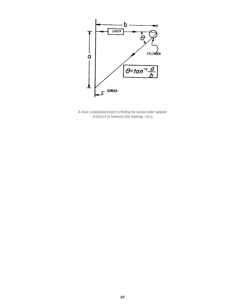
49
A more complicated project is finding the second order rainbow--0-(H,G)-S in Newton’s first drawing—try it.

50
EXPERIMENT 25. REFLECTION
9010
011
0
120
130
140
150
160170 80
0
100
110
120
130
140150
160170 18
8070
60
50
40
3020
10
8070
60
50
40
30
2010
Laser
Beam Stop
Protractor
Mirror
1585.eps
Overview
When light encounters the boundary between two surfaces with differ-ent optical densities, some or all of the energy will be reflected. In thisinvestigation we will examine several types of reflection with a laserbeam.
Procedure
A. Types of Reflection
1. Investigate the reflective abilities of several different types of mate-rials included in the Optics Education Kit. Materials such as flat mir-rors provide specular reflection, which changes the direction of thebeam without scattering or diffusing the light. Rough objects suchas unpolished metal, paper or wood reflect the light at the sametime as they scatter it. Point the laser beam at a variety of solids andliquids, and observe the reflection by holding a piece of glossy papernear the object to catch the reflected light. In each case, record thetype of material tested and the appearance of the reflected laserlight.
2. Using a microscope slide or the specially designed beam splitter(part # 45-728), investigate the phenomenon of partial reflection aspart of a laser beam is transmitted through a material and part of itis reflected at the surface. Observe the relative intensity of the trans-mitted and reflected portions of the beam as the glass is tilted at var-ious angles to the incident beam. Record your observations.
3. Shine the beam into a tank of water and observe that reflections willtake place not only when the beam enters the water, but also whenthe beam is leaving the water from a different side of the tank.Reflections that tend to keep the laser beam inside of a medium areknown as internal reflections. The intensity of the internal reflectiondepends on the angle that the beam strikes the surface. Set up anexperiment to determine the relative amount of internal reflectionas the angle between the laser beam and the surface varies.
B. Law of Reflection
The law of reflection states that the angle of incidence is equal to theangle of reflection. It also states that the incident ray, normal ray andreflected ray all lie on the same plane. This can be verified with preci-sion by using the laser and the technique outlined below. The itemsused for the experiment are also available in the IFO IF-548 Light RayViewing Kit.
1. Pour 1.7 liters of warm water (65°C /150 °F) into a clear pan. Addseven drops of IFO scattering solution IF-850005 to the water andstir gently for several seconds.
2. Position the laser on a table so that the beam passes through thesolution as shown in the Figure. Center and tape a flat mirror wherethe spot appears in the back of the pan. Place a protractor in the bot-tom of the pan and roughly center it beneath the beam as shown.
3. Look down at the pan and adjust the laser so that it enters the tankand hits the flat mirror at an angle as shown. Position the beam stopso the reflected laser beam strikes the beam stop as shown in theFigure.
4. Position the protractor so that the center marking is directly underwhere the beam hits the flat mirror. Adjust the laser beam until it pass-es over the 100 degree and center markings of the protractor. Note:This is 10 degrees from a normal drawn through where the laser hitsthe flat mirror (90 degree marking on protractor). Look at the reflect-ed beam and record the angle marking on the protractor over whichit passes.
5. Repeat step 4 but use the 110 degree marking (20 degrees from nor-mal) on the protractor.
6. Review your recorded data. Calculate the angle in degrees awayfrom the 90 degree normal for the incident and reflected rays.According to the law of reflection the incident angle (in degreesaway from the normal) should equal the reflected angle.
Proving the law of reflection using laser beam and long distance measuring techniques.

51
EXPERIMENT 26. MEASURING THE CRITICAL ANGLE
90
100
110
120
130
140
150
160
170
80
0
100110 120 130 140 150
160170
18
8070 60 50 40
3020
10
80
70
6050
4030
2010
Laser
Beam Stop
Scattering Tank Filled With Water1587.eps
ReflectedRay
Overview
When light travels from any medium into a vacuum, a critical angle ofincidence is associated with internal reflections in the material at theboundary with the vacuum. Light rays approaching the boundary at anangle that equals or exceeds this critical angle don’t emerge — all of thelight will be reflected internally. Measuring the critical angle of a mate-rial is easily done using a fine laser beam.
Procedure
The items used for the experiment are also available in the IFO IF-548Light Ray Viewing Kit.
A. Determine the critical angle of water by adding some to a transpar-ent tank. Add seven drops of IFO scattering solution IF-850005 tothe water and stir gently for several seconds. Aim the laser beam
into the left side of the tank as shown in the diagram above.
B. Rotate the tank slowly in each direction until the laser beamemerges only from the back of the tank with no reflections insidethe tank.
C. Slowly rotate the tank counter-clockwise until the beam just beginsto totally reflect inside the tank. Drop a protractor into the tank andmeasure the angle between the laser beam and the normal to thesurface it strikes at the rear of the tank. This is the critical angle forthe water.
Note that the acrylic tank contributes an error term to the criticalangle measured for the water since it has a different index of refrac-tion. The error is relatively small because the acrylic is fairly thinand its refractive index isn’t radically different than water.
Total internal reflection of the laser beam

52
EXPERIMENT 27. MEASURING THE INDEX OFREFRACTION OF LIQUIDS
Overview
Because the laser beam is so narrow and bright, it not only provides aready means for measuring the index of refraction of homogeneous liq-uids, but also can be used to locate and measure non-homogeneities aswell.
Procedure
A. Determine the index of refraction for water by adding some to atransparent tank. Add seven drops of IFO scattering solution IF-850005 to the water and stir gently for several seconds. Aim thelaser beam into the left side of the tank roughly in the center asshown in the diagram above. Using a protractor rotate the tank untilthe incident angle between the beam and the surface normal whereit enters the tank is 30 degrees. Measure the angle between the nor-mal and the refracted ray inside the tank. Calculate the index ofrefraction of water, using the relationship:
Where: n = index of refractioni = angle of incident rayr = angle of reflected ray
B. Change the angle of incidence to several different values then cal-culate the index of refraction of water for each trial.
C. Substitute a variety of transparent liquids for water and measure theindex of refraction of each, following the steps above. Alcohol andglycerin are suitable materials for this investigation.
D. Investigate the gradual bending of light that occurs when a laserbeam is transmitted through a solution in which the optical densityis not constant. This can be done by filling the bottom of a fish tankto a depth of 5 to 10 cm with a solution of sugar and water. Try dif-ferent concentrations of sugar and water.
E. A technique to investigate the rates of diffusion between two liquidsof different indexes of refraction was described by Barnard andAhlborn (American Journal of Physics, July 1975, p. 573). A celltwo inches square containing photographic Rapid Fix was slowlyfilled to the top with plain water. A beam spreader was attached tothe laser to spread the beam into a thin line, making a 45º anglewith the vertical. It was passed through the liquid-filled cell and thebeam trace observed on a screen on the far side of the cell. As thetwo liquids diffused over a time of approximately 30 minutes, theshape of the trace changed in a predictable manner. Additionaldetails can be found by referring to this interesting article.
ri
nsinsin
=
90
100
110
120
130
140
150
160
170
80
0
100110 120 130 140 150
160170
18
8070 60 50 40
3020
10
80
70
6050
4030
2010
Laser
Beam Stop
Protractor
Scattering Tank Filled With Water
1622.eps
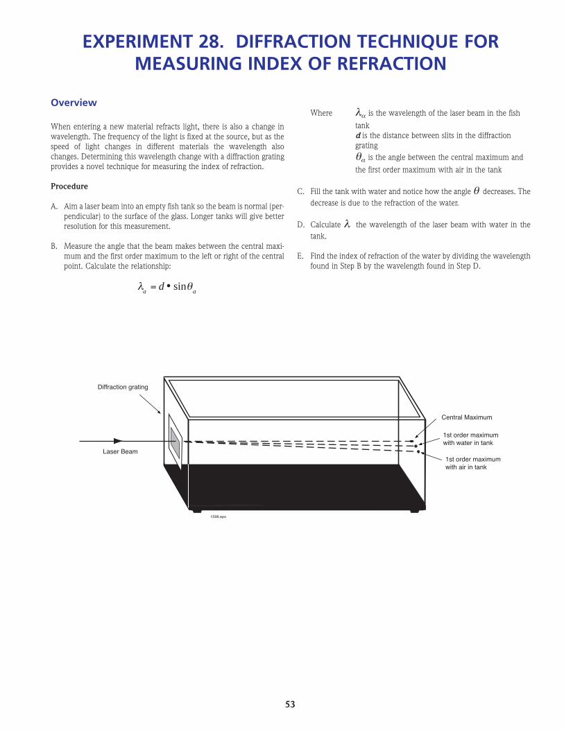
53
EXPERIMENT 28. DIFFRACTION TECHNIQUE FORMEASURING INDEX OF REFRACTION
Diffraction grating
Central Maximum
1st order maximumwith air in tank
1st order maximumwith water in tank
Laser Beam
1598.eps
Overview
When entering a new material refracts light, there is also a change inwavelength. The frequency of the light is fixed at the source, but as thespeed of light changes in different materials the wavelength alsochanges. Determining this wavelength change with a diffraction gratingprovides a novel technique for measuring the index of refraction.
Procedure
A. Aim a laser beam into an empty fish tank so the beam is normal (per-pendicular) to the surface of the glass. Longer tanks will give betterresolution for this measurement.
B. Measure the angle that the beam makes between the central maxi-mum and the first order maximum to the left or right of the centralpoint. Calculate the relationship:
Where λα is the wavelength of the laser beam in the fish
tank d is the distance between slits in the diffractiongrating θα is the angle between the central maximum and
the first order maximum with air in the tank
C. Fill the tank with water and notice how the angle θ decreases. Thedecrease is due to the refraction of the water.
D. Calculate λ the wavelength of the laser beam with water in thetank.
E. Find the index of refraction of the water by dividing the wavelengthfound in Step B by the wavelength found in Step D.
aad θλ sin•=

54
EXPERIMENT 29. DOPPLER EFFECT
Overview
The Doppler effect is a well-known phenomenon where the apparentfrequency of waves from a source are changed when the source orobserver are in motion. Using the IFO photometer (supplied as anoptional accessory), we can readily demonstrate the Doppler effect onlight waves.
Procedure
A. Set up the laser, beam splitter and two front surface mirrors in themanner described in Experiment 13 on the Michelson interferome-ter. Instead of using a plano-convex lens to display the interferencepattern on a screen, superimpose the two reflected beams on thedetector of the photometer.
B. Set the range switch of the photometer to its middle position.
C. Connect the output of the photometer to any audio amplifier andspeaker, using the jack at the side of the photometer for this pur-pose.
D. Move one of the front surface mirrors back and forth very slowly.You will hear a tone from the loudspeaker.
The frequency of light is too high to directly produce an audibletone. But when one of the front surface mirrors is moved slowly,there is an apparent change in the wavelength of light in its path.This Doppler shift in wavelength causes movement of the interfer-ence fringes generated between the stationary reference beam andthe beam affected by the mirror motion. The fringes move at a ratewithin the audio frequency range, and the amplitude variations aredetected by the photodetector and reproduced as sound. The fre-quency of the sound is directly proportional to the rate at which themirror is moved. Rapid movements however produce frequencychanges higher than the audible range and can’t be heard.
E. Try to devise a mechanical mechanism that can advance one of themirrors at a uniform speed, to produce a steady tone, or at a variablespeed to produce a tone that fluctuates in frequency.

55
ADDITIONAL EXPERIMENTSFOR ADVANCED STUDY
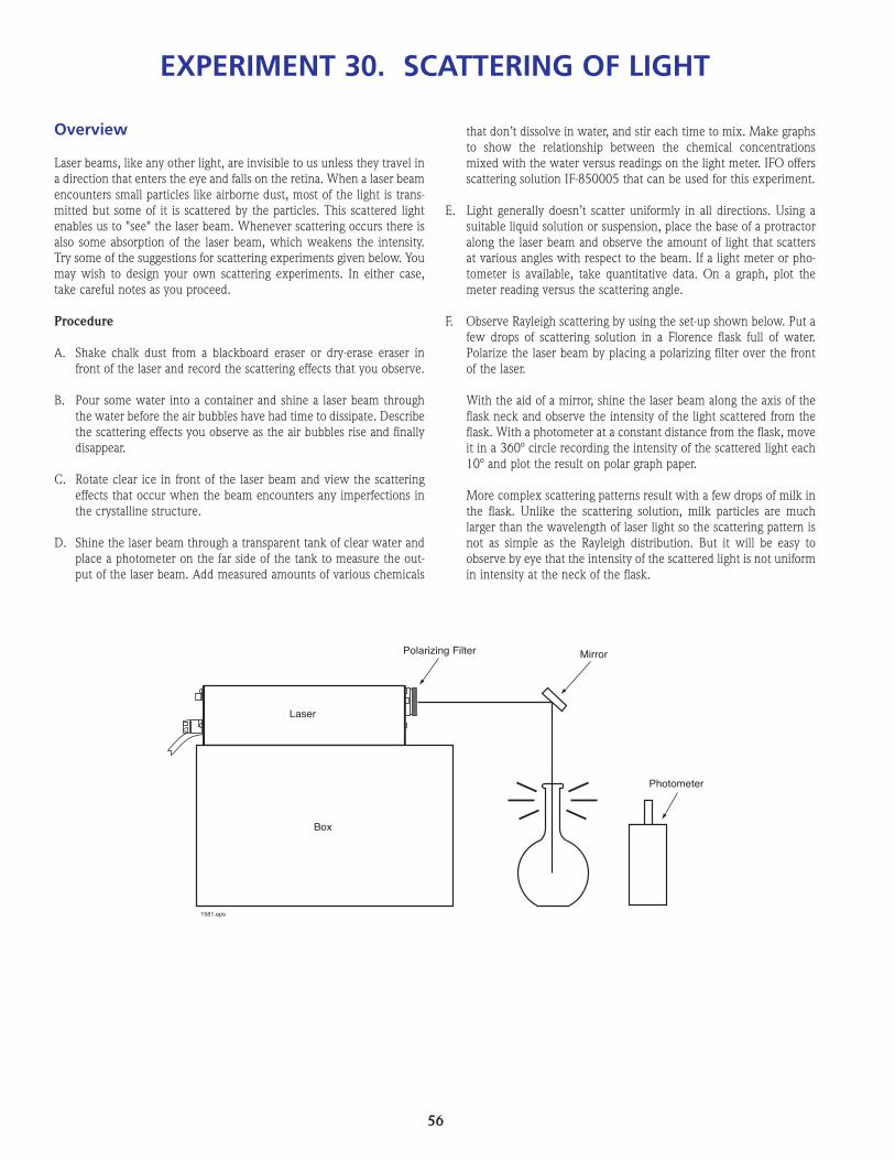
56
Overview
Laser beams, like any other light, are invisible to us unless they travel ina direction that enters the eye and falls on the retina. When a laser beamencounters small particles like airborne dust, most of the light is trans-mitted but some of it is scattered by the particles. This scattered lightenables us to "see" the laser beam. Whenever scattering occurs there isalso some absorption of the laser beam, which weakens the intensity.Try some of the suggestions for scattering experiments given below. Youmay wish to design your own scattering experiments. In either case,take careful notes as you proceed.
Procedure
A. Shake chalk dust from a blackboard eraser or dry-erase eraser infront of the laser and record the scattering effects that you observe.
B. Pour some water into a container and shine a laser beam throughthe water before the air bubbles have had time to dissipate. Describethe scattering effects you observe as the air bubbles rise and finallydisappear.
C. Rotate clear ice in front of the laser beam and view the scatteringeffects that occur when the beam encounters any imperfections inthe crystalline structure.
D. Shine the laser beam through a transparent tank of clear water andplace a photometer on the far side of the tank to measure the out-put of the laser beam. Add measured amounts of various chemicals
that don’t dissolve in water, and stir each time to mix. Make graphsto show the relationship between the chemical concentrationsmixed with the water versus readings on the light meter. IFO offersscattering solution IF-850005 that can be used for this experiment.
E. Light generally doesn’t scatter uniformly in all directions. Using asuitable liquid solution or suspension, place the base of a protractoralong the laser beam and observe the amount of light that scattersat various angles with respect to the beam. If a light meter or pho-tometer is available, take quantitative data. On a graph, plot themeter reading versus the scattering angle.
F. Observe Rayleigh scattering by using the set-up shown below. Put afew drops of scattering solution in a Florence flask full of water.Polarize the laser beam by placing a polarizing filter over the frontof the laser.
With the aid of a mirror, shine the laser beam along the axis of theflask neck and observe the intensity of the light scattered from theflask. With a photometer at a constant distance from the flask, moveit in a 360º circle recording the intensity of the scattered light each10º and plot the result on polar graph paper.
More complex scattering patterns result with a few drops of milk inthe flask. Unlike the scattering solution, milk particles are muchlarger than the wavelength of laser light so the scattering pattern isnot as simple as the Rayleigh distribution. But it will be easy toobserve by eye that the intensity of the scattered light is not uniformin intensity at the neck of the flask.
EXPERIMENT 30. SCATTERING OF LIGHT
Box
Laser
MirrorPolarizing Filter
Photometer
1581.eps
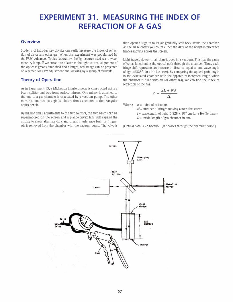
57
EXPERIMENT 31. MEASURING THE INDEX OFREFRACTION OF A GAS
Overview
Students of introductory physics can easily measure the index of refrac-tion of air or any other gas. When this experiment was popularized bythe PSSC Advanced Topics Laboratory, the light source used was a weakmercury lamp. If we substitute a laser as the light source, alignment ofthe optics is greatly simplified and a bright, real image can be projectedon a screen for easy adjustment and viewing by a group of students.
Theory of Operation
As in Experiment 13, a Michelson interferometer is constructed using abeam splitter and two front surface mirrors. One mirror is attached tothe end of a gas chamber is evacuated by a vacuum pump. The othermirror is mounted on a gimbal fixture firmly anchored to the triangularoptics bench.
By making small adjustments to the two mirrors, the two beams can besuperimposed on the screen and a plano-convex lens will expand thedisplay to show alternate dark and bright interference bars, or fringes.Air is removed from the chamber with the vacuum pump. The valve is
then opened slightly to let air gradually leak back inside the chamber.As the air re-enters you count either the dark or the bright interferencefringes moving across the screen.
Light travels slower in air than it does in a vacuum. This has the sameeffect as lengthening the optical path through the chamber. Thus, eachfringe shift represents an increase in distance equal to one wavelengthof light (6328Å for a He-Ne laser). By comparing the optical path lengthin the evacuated chamber with the apparently increased length whenthe chamber is filled with air (or other gas), we can find the index ofrefraction of the gas:
Where: n = index of refractionN = number of fringes moving across the screenl = wavelength of light (6.328 x 10⁻⁵ cm for a He-Ne Laser)L = inside length of gas chamber in cm.
(Optical path is 2L because light passes through the chamber twice.)
LNL
n2
2 λ+=

58
In a typical run, we counted 44 fringes when using a chamber 6.3 cm.long. The index of refraction of air was calculated to be 1.00022, whichcompares favorably with the handbook value of 1.00029.
Procedure
A. Mount a laser, Maggie Mount platform and gimbaled mirror on thetriangular optics bench as shown in the illustration. Attach the laserto the adjustable laser carrier and aim it directly at the mirror in thegimbal mount at the opposite end of the triangular optics bench. Ifnecessary, use the rectangular spacer to raise the laser to the samelevel as the mirror. The Maggie platform must be screwed into itscarrier and firmly mounted on the optics bench.
B. On the Maggie Mount platform, mount the gas cell, beam splitterand plano-convex lens in the positions shown. Attach the gas cell toa vertical Maggie carrier with an L Maggie carrier below the gas cellto provide additional support. The beam splitter and plano-convexlens also are mounted on vertical Maggie mounts. Adjust the dis-tances between the two mirrors on the platform so they are approx-imately equidistant from the beam splitter.
C. Adjust the positions of the beam splitter and the two mirrors so thesplit laser beams are directed through the plano-convex lens andsuperimposed on a screen to form an interference pattern of light
and dark fringes. Fine adjustments for clear, heavy fringes are possi-ble with the adjustments on the gimbaled mirror and on theadjustable laser carrier.
D. Close the valve on the vacuum tubing and operate the hand pumpto evacuate the air in the gas chamber. From this point, it is essen-tial that you keep the optical components perfectly still – withoutthe slightest movement or vibration. If necessary, clamp the tubingto a firm support such as a bench clamp or a ring-stand.
E. Very, very slowly, open the vacuum valve and let the air or other gasenter the chamber. As it enters, note that fringes in the interferencepattern shift from right to left. Count the total number of fringes thatpass a spot in the center of the screen from the time that the valveis opened until the time the pressure gauge indicates that the gaschamber is refilled.
F. To find the index of refraction of carbon dioxide, hydrogen, or anyother common gases that are available in lecture table flasks, evac-uate the air from the gas chamber with a vacuum pump and thenpurge the gas chamber once or twice with the desired gas attachedto the gas inlet. When you are certain that no air remains in thechamber or the connecting tubing, operate the apparatus to find theindex of refraction of the gas.

59
EXPERIMENT 32. AMPLIFICATION OF MOVEMENT
Overview
A laser beam is very bright and diverges only a small amount under ordi-nary laboratory conditions. This makes it an ideal device for opticalamplification of small and almost imperceptible mechanical movements.With a little ingenuity, we can invent many original devices by using theprinciples of optical amplification to solve both practical and scientificproblems.
Procedure
A. Laser Galvanometer
1. Wind 20 turns of insulated wire around a cylindrical form such as ascrewdriver handle. Remove the screwdriver, tape the coils togeth-er, and suspend them from two thin strands of wire attached to thetwo end tips of the coil. The longer the suspension wires, the moresensitive the galvanometer.
2. Using a small piece of cellulose tape or double-sided tape, fasten thecoil to the thin mirror supplied with the Optics Education Kit.
3. Suspend the coil and mirror between the poles of a horseshoe mag-net as shown in the diagram.
4. Be careful that the laser beam or its reflection doesn’t enter anyone’seyes. Aim the laser at the mirror and observe its reflection on a dis-tant wall. When a small amount of electric current is applied to thecoil, the mirror will twist making a large deflection of the laserbeam.
5. Using appropriate resistive shunts and multipliers, calibrate the gal-vanometer to read amperes and volts. A standard ammeter or volt-meter may be used for comparison.
B. Heart Pulse Indicator
1. Fasten a small mirror to your wrist, directly over the point whereyou feel your heart pulse beat. Adhesive tape will adhere to the skinbetter than cellulose or electrical tape for this purpose.
2. Be careful that the laser beam and its reflection doesn’t enter any-one’s eye. Aim the laser at the mirror and observe its reflection ona distant wall.
3. With your wrist held steady on a table, you will see that very smallmovements of the mirror caused by the pulse beat show up as largedeflections on the wall. With care, you can measure the amplitudeof the beat as well as the rate.
C. Laser Oscilloscope
Using the principles of optical amplification, we can project Lissajouspatterns on a distant wall, and demonstrate the principles of an oscillo-scope.
1. Mount two 3-inch radio speakers in a frame as shown in the fol-lowing diagram.
2. Glue the tip of a wooden dowel to one end of each speaker. Gluethe other end of each dowel to thin plastic strips cut from a flexibleplastic ruler like the one furnished with the Optics Education Kit
3. Attach the free ends of the plastic strips to the frame and cement thesmall mirror over the intersection of the plastic strips.
4. Being careful that the laser beam and its reflection do not enter peo-ple’s eyes, aim the laser at the mirror and observe its reflection on adistant wall.
5. Connect an audio generator to speaker 1 and another audio oscilla-tor to speaker 2. By adjusting the frequencies of each audio oscilla-tor, we can produce a variety of large Lissajous patterns on the wall.Speaker 1 produces horizontal deflections of the beam, and speaker2 produces vertical deflections.
Mirror
Mirror
Thin Wire
Thin Wire
Wire Coil
Magnet
Tape
TapedWireCoil
610.eps
Speaker#1
Speaker#2
PlasticStrip
Mirror
Wood dowelgluedto center
1611.eps

60
EXPERIMENT 33. ALIGNMENT
On
Beam Stop
Target
TargetSmall Hole
Example of Target
1614.eps
Overview
Many helium-neon lasers are used as alignment tools. For instance,many high-powered lasers emit light in the ultraviolet and infraredregions just outside of human visibility. Without a visible reference, itbecomes extremely time consuming to place lenses, spatial filters, beamsplitters and mirrors in the path of such high power lasers. The helium-neon laser solves the alignment problem quite handily. Its red gleamclearly indicates the light path and allows lenses and other optical com-ponents to be properly positioned.
The IFO Optics Set can be used to provide alignment practice.
Begin by making two or more target cards. Each should have a smallhole through which the beam can pass.
A. Align the axes of optics benches to a parallel line in space.
1. Align the laser beam with the most distant bench first. As agood safety practice, place a beam stop at the far end of thework area. Place the target on the far end of that bench. Swingand tilt the laser until the beam is centered on the target.
2. Slide the target to the near end of the bench farthest from thelaser. Adjust this end of the bench, being careful not to disturbthe far end, until the beam is centered on the target.
3. Move the target toward the far end of the bench again, makingsmall adjustments in bench height until the beam remains ontarget as the target is moved along the entire length of thebench.
More benches can be added. Adjust the newest (closest to thelaser) bench only, being careful not to disturb the laser or thefirst (furthest) bench.

61
#
#
#
1615.eps
B. Align the lenses. Lenses and other elements may be centered andsquared-on (perpendicular to the beam axis) using the laser.Generally, the least effort is needed if conjugates are set from theimage furthest back; then other elements are roughly aligned; thenalignment is completed using the laser. Make use of the shape andposition of both the reflected and transmitted beams in centeringand squaring lenses. Figures 2 to 5 show typical conditions.
1. Figure 2. With no lens in the system, center a target on thebeam. The beam should be round.
2. Figure 3. With lens in place, centered and squared-on:
a. The transmitted beam remains centered and round,although its size may change.
b. The reflected beam returns along the same path from whichit came. It may be necessary to center a small aperture somedistance in front of the beam in order to check this.
3. Figure 4. If the lens is square on but not centered, the transmit-ted beam will move off center.
4. Figure 5. If the lens (or mirror) is not squared-on:
a. The reflected beam is deviated.
b. The transmitted beam may not be round.
Generally, 3 and 4 occur simultaneously, so you may need toadjust for both. After you center a lens, it may be necessary toplace a target in front of it, center the target, then center andsquare the next lens forward. Repeat this procedure until alllenses are in position.
Practice will demonstrate that different arrangements mayrequire variations on these procedures.
C. To align a folded system of almost any configuration, set up smallapertures centered on beam as described in Step A. Introduce planemirrors at appropriate points. Center mirrors to beam, tilt to properorientation. It may be necessary to make small, multiple movementsto keep beam centered while mirror is being tilted.
Derived from an experimentcontributed by Martin DvorinOptical Technology DepartmentMonroe Community CollegeRochester, New York 14623
Figure 1. Beam centered on target.
Figure 2. Lens added, centered, squared on.
Figure 3. Lens not centered.
Figure 4. Lens not squared on.

62
EXPERIMENT 34. MEASURING THE SPEED OF LIGHT
Photodetector 2 - Output toOscilloscope
Photodetector 1 - Output toOscilloscope
Fresnel Lens
About 120 meters
BeamSplitter
Collimator
Signal Generator
Modulated Laser
AdjustableMirror
Overview
Because light can travel about seven and a half times around the earthin one second, measurements of this speed in the student lab have beenvery difficult. Now, with low-cost He-Ne lasers that can be modulated atradio frequencies, and low-cost, high frequency photodetectors, stu-dents can make measurements that rival those of Fizeau and Michelson.Once the basic technique has been mastered, other open-ended experi-ments can be performed under a variety of environmental conditions.
This experiment can be performed outdoors in a wide-open area orbetween buildings that are at least 120 meters apart. The best time ofday is early morning or evening, when wind and thermal air currents areat a minimum.
Note: As an alternative, the speed of light measurement can now bemade in the classroom (over a distance of 20 meters) with the ML-868modulated laser. Set-up and takedown time is only a few minutes.Results can be displayed and easily understood with a dual channel oscil-loscope. This IFO “Speed of Light/Laser Audio Kit” is part # 45-720. Seethe rear of this manual for details about the modulated laser and the kit.
For our outdoor demonstration, in addition to the lenses and mirrorsincluded in the Optics Education Kit, you will need two photodetectorsand a modulatable He-Ne laser. (The experiment can be performed withone photodetector, but it’s easier with two.) You’ll also need an oscillo-scope with 1 MHz bandwidth and 50-100 mV/cm sensitivity, alongwith an RF signal generator capable of frequencies from a few kHz to 1MHz.
The RF signal generator is connected to a low power (1mW) modulat-able He-Ne laser and varies the amplitude of the beam at frequencies upto 1MHz. A simple collimates the beam to produce a uniform spot about
2cm in diameter. Part of the beam is directed by a beam splitter (or smallmirror) into a photodetector. This photodetector produces a referencesignal that will be displayed on the oscilloscope.
Most of the laser light travels to an adjustable mirror approximately120m away and reflects back through a Fresnel lens to the other pho-todetector. The output of this photodetector is also fed to the oscillo-scope. If the amplitudes of the two beams are equal, and if the longerbeam arrives at the photodetector one-half wavelength after the refer-ence beam, complete destructive interference occurs. This causes thewaveform on the oscilloscope to disappear.
To create this interference, we make the traveled path 240 meterslonger than the reference beam path. Then we increase the frequencyfrom the signal generator from zero until we see a null on the oscillo-scope. The null indicates that the distant beam is arriving one half wave-length after the reference beam. Since the frequency of the signal gen-erator is known, it is easy to calculate the time delay that produces thehalf wavelength shift. We then divide the distance by the time, whichgives us the speed of light.
In a sample run outdoors in full daylight, the adjustable mirror wasplaced 120 meters away. A null was produced when we set the signalgenerator at 600 kHz. The period of this signal is 1/(6x105) sec (1.67_S). The travel time for a half-wavelength is _ x 1.67 _S or 0.83 _S.Dividing the total distance, 240m, by the travel time gives the speed oflight as 2.89 x 10⁸ m/sec.
Procedure
1. Connect the output of an RF signal generator to the connector at therear of the laser. Any standard RF signal generator will do, but it isessential to use a laser that can be modulated at radio frequencies.

63
2. Collimate and expand the laser to produce a beam about 2cmindiameter. This can be done with a converging and plano-convex lenssystem. Test the collimation by holding a screen in front of the laserand checking that the beam diameter remains constant at distancesup to 50 meters away.
3. Divert part of the beam into a photodetector with a small mirror orbeam splitter. Connect the photo-detector output to the oscillo-scope. Check that the signal generator is modulating the laser beamby observing the photodetector’s waveform as the generator fre-quency is changed
4. Project the rest of the beam to the distant mirror and couple thereflected beam onto the second photodetector with the Fresnel lens.This task is more difficult if you are using only one photodetector.The return beam must be reflected by another mirror before passingthrough the Fresnel lens. It may take students a few hours to alignthe system because of the distances involved. You may have betterluck in the early evening or in a long school corridor. IFO’s Speed of
Light Kit (45-720) comes with adjustable and fixed mirrors, mount-ings and other accessories for rapid alignment.
5. Adjust the amplitudes of the two photodetector signals to producewaveforms of equal height on the oscilloscope using the verticalcontrols. If you use only one photodetector, the signals can be bal-anced by partially masking the mirror that reflects the more intensebeam.
6. Start at the lowest frequency setting and slowly increase the fre-quency of the signal generator. At low frequencies, the two beamsare almost in phase and will interfere constructively, producing acombined signal of relatively high amplitude. As the frequencyincreases, the relative phase shift increases and the amplitude of thewaveform on the oscilloscope decreases. When the two signals areexactly 180° out of phase, they will produce a null, and only astraight horizontal line appears on the oscilloscope. Record the fre-quency at which this happens and calculate the speed of lightaccording to the calculation outlined above.

64
NOTES:
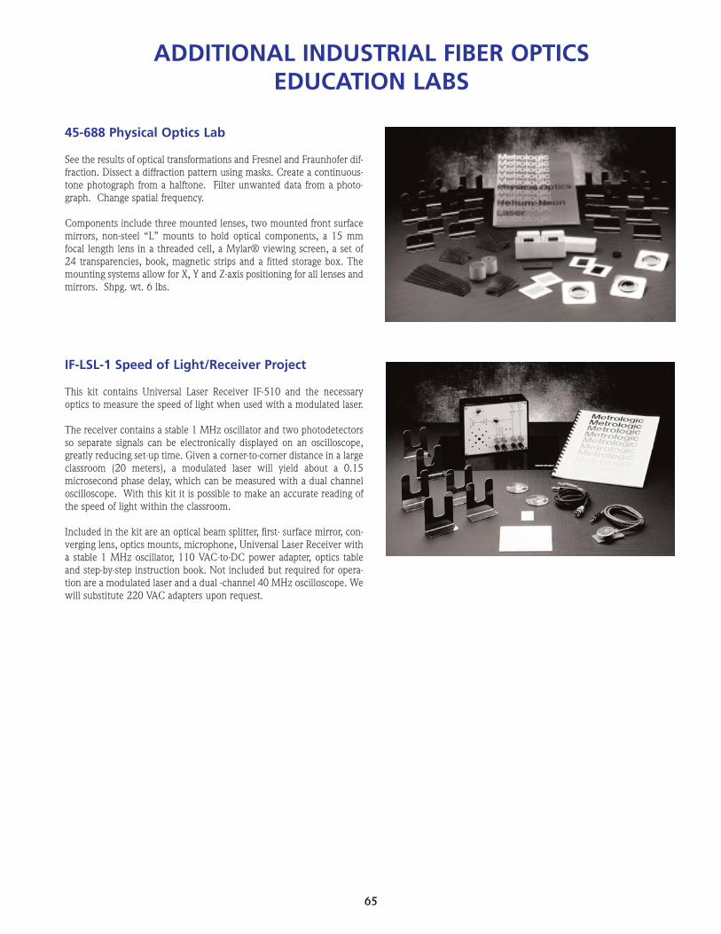
65
45-688 Physical Optics Lab
See the results of optical transformations and Fresnel and Fraunhofer dif-fraction. Dissect a diffraction pattern using masks. Create a continuous-tone photograph from a halftone. Filter unwanted data from a photo-graph. Change spatial frequency.
Components include three mounted lenses, two mounted front surfacemirrors, non-steel “L” mounts to hold optical components, a 15 mmfocal length lens in a threaded cell, a Mylar® viewing screen, a set of24 transparencies, book, magnetic strips and a fitted storage box. Themounting systems allow for X, Y and Z-axis positioning for all lenses andmirrors. Shpg. wt. 6 lbs.
IF-LSL-1 Speed of Light/Receiver Project
This kit contains Universal Laser Receiver IF-510 and the necessaryoptics to measure the speed of light when used with a modulated laser.
The receiver contains a stable 1 MHz oscillator and two photodetectorsso separate signals can be electronically displayed on an oscilloscope,greatly reducing set-up time. Given a corner-to-corner distance in a largeclassroom (20 meters), a modulated laser will yield about a 0.15microsecond phase delay, which can be measured with a dual channeloscilloscope. With this kit it is possible to make an accurate reading ofthe speed of light within the classroom.
Included in the kit are an optical beam splitter, first- surface mirror, con-verging lens, optics mounts, microphone, Universal Laser Receiver witha stable 1 MHz oscillator, 110 VAC-to-DC power adapter, optics tableand step-by-step instruction book. Not included but required for opera-tion are a modulated laser and a dual -channel 40 MHz oscilloscope. Wewill substitute 220 VAC adapters upon request.
ADDITIONAL INDUSTRIAL FIBER OPTICSEDUCATION LABS

66
Laser Communications Kit45-920 w/ML211 laser pointer 45-921 w/ML215 laser pointer
IFO presents an updated version of its popular Laser Communicationskit. Now with a 5 MHz receiver you can transmit audio, and qualityblack-and-white color video. Use this kit to bring modern technology toyour classroom by teaching the principles of light-based transmission.This kit provides a laser pointer modulator allowing you to modulateeither of IFO’s pointers.
The kit works by receiving light from a distant audio or video modulat-ed laser. It detects, amplifies and reproduces voice, music, or videocommunications. An output is provided for a video monitor to repro-duce pictures.
Included in the Communications Kit are a modulator, pointer holder,receiver, high impedance microphone, optical platform, three U-shapedMaggie Mounts and easily understood instruction manual. For the 45-920 kit add a ML211 3 mW class IIIA laser pointer (675 nm) and forthe 45-921 kit add a ML215 3mW class IIIA laser pointer (635 nm).
Note: Not included but required for operation are a video camera orVCR and monitor.
Michelson Interferometer45-940 w/ML211 laser pointer45-941 w/ML215 laser pointer45-942 without laser pointer
This kit contains a set of optical components and mountings for easyassembly of a Michelson interferometer. This is a classic device for split-ting a beam of monochromatic light into two parts that travel along dif-ferent optical paths and then merge again to produce interferencefringes. The fringes shift noticeably in response to even almost imper-ceptible movement of one of the optical components. They also will shiftwhen the effective length of one optical path changes slightly withrespect to the second. These shifts make it possible to measure changesof a medium’s index of refraction and microscopic movements of com-ponents.
The Michelson Kit includes four U-shaped carriers, two L-shaped carri-ers, two magnetic strips, a short-focal-length lens, laser pointer holderand instruction manual. For the 45-940, add a ML211 3 mW class IIIAlaser pointer (675 nm), and for the 45-941 add a ML215 3 mW classIIIA laser pointer (635 nm).
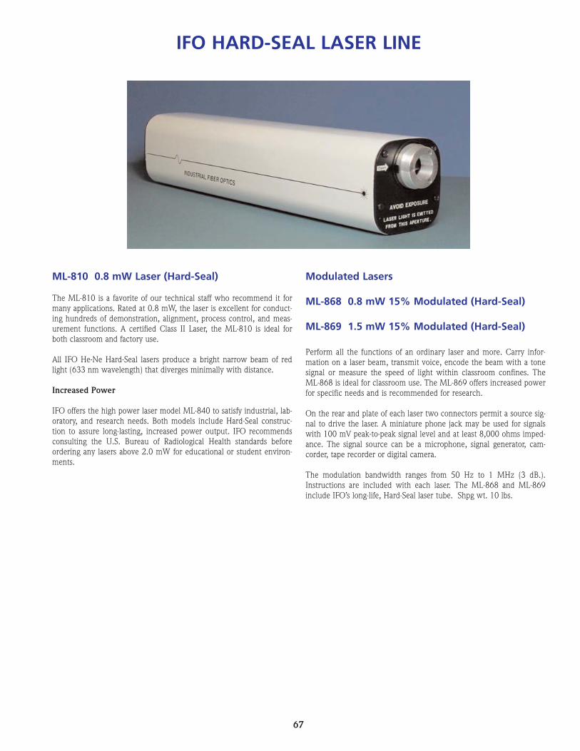
67
ML-810 0.8 mW Laser (Hard-Seal)
The ML-810 is a favorite of our technical staff who recommend it formany applications. Rated at 0.8 mW, the laser is excellent for conduct-ing hundreds of demonstration, alignment, process control, and meas-urement functions. A certified Class II Laser, the ML-810 is ideal forboth classroom and factory use.
All IFO He-Ne Hard-Seal lasers produce a bright narrow beam of redlight (633 nm wavelength) that diverges minimally with distance.
Increased Power
IFO offers the high power laser model ML-840 to satisfy industrial, lab-oratory, and research needs. Both models include Hard-Seal construc-tion to assure long-lasting, increased power output. IFO recommendsconsulting the U.S. Bureau of Radiological Health standards beforeordering any lasers above 2.0 mW for educational or student environ-ments.
Modulated Lasers
ML-868 0.8 mW 15% Modulated (Hard-Seal)
ML-869 1.5 mW 15% Modulated (Hard-Seal)
Perform all the functions of an ordinary laser and more. Carry infor-mation on a laser beam, transmit voice, encode the beam with a tonesignal or measure the speed of light within classroom confines. TheML-868 is ideal for classroom use. The ML-869 offers increased powerfor specific needs and is recommended for research.
On the rear and plate of each laser two connectors permit a source sig-nal to drive the laser. A miniature phone jack may be used for signalswith 100 mV peak-to-peak signal level and at least 8,000 ohms imped-ance. The signal source can be a microphone, signal generator, cam-corder, tape recorder or digital camera.
The modulation bandwidth ranges from 50 Hz to 1 MHz (3 dB.).Instructions are included with each laser. The ML-868 and ML-869include IFO’s long-life, Hard-Seal laser tube. Shpg wt. 10 lbs.
IFO HARD-SEAL LASER LINE

68
CLEANING INSTRUCTIONS
Before sub-assembly and/or installation in the Optics Box, clean the following com-ponents with tissues and the solvents indicated.
1. Clean the following parts only with water:
PART CATALOG NUMBER
Lens 45-631Lens 45-657Lens 45-654Lens 45-652
2. Clean the following parts only with Methyl Alcohol, optics grade:
PART CATALOG NUMBER
Air Film Wedge 45-661Mirrors 2 pcs 45-646Polished Beam Splitter 45-728Prism 45-726
All parts should be dried with tissues immediately after cleaning to avoid spotting.