experimental study of rigid connection of drilled beam to
TRANSCRIPT
Journal of Constructional Steel Research 153 (2019) 209–221
Contents lists available at ScienceDirect
Journal of Constructional Steel Research
Experimental study of rigid connection of drilled beam to CFT columnwith external stiffeners
Nader Fanaie, Hossein Sadeghi Moghadam ⁎Department of Civil Engineering, K. N. Toosi University of Technology, Tehran, Iran
⁎ Corresponding author at: University of Technology, Ci1346, Vali-Asr Street, P.O. Box. 15875-4416, 19697 Tehran
E-mail address: [email protected] (H.S. Mogha
https://doi.org/10.1016/j.jcsr.2018.10.0160143-974X/© 2018 Published by Elsevier Ltd.
a b s t r a c t
a r t i c l e i n f oArticle history:Received 14 June 2018Received in revised form 10 October 2018Accepted 17 October 2018Available online xxxx
This research is intended to investigate the behaviour of rigid connection of steel beam to CFT column withexternal T stiffeners. However, the investigations have shown that the stress concentration in the location of stiff-ener groovewelds to the beam flange and columnweb causes abrupt fragile failure leading to ductility reductionof the connection. In the current study, beam section is reduced using themethod of drilling beam flange so as todiminish the stress concentration and increase the ductility. Thismethod ismuch easier to fabricate compared toRBS (cutting with CNC machine) and more applicable for existing buildings as well. In this research project twoseries of analytical models with constant and variable holes are investigated to evaluate the effects of differentparameters of drilling on the local behavior of connections. Finite element method using ABAQUS software hasbeen employed for analyses. In another part of this survey, two full scale samples are selected out of the analyticalmodels, and experimentally investigated. According to the obtained results, drilling the beam flange results indecrease in stress concentration in the connection location of stiffener to the beam and column. In addition, itdecreases the probability of failure in the expected modes 1 (shear failure of T-shaped horizontal stiffener) and2 (tension failure of T-shaped vertical stiffener in connection to the column web) and increase the ductility ofconnection. Moreover, such connections can be used in the intermediate as well as special moment resistingframes.
© 2018 Published by Elsevier Ltd.
Keywords:Rigid beam to column connectionConcrete Filled Tube (CFT) columnT-shaped stiffenerBeam drillingReduced Beam Section (RBS)
1. Introduction
Concrete and steel are the most common materials in the construc-tion of structures, each of which has its own advantages. Concrete FilledTube (CFT) columns combine the ductility of steel with stiffness of con-crete. Such columns consist of a steel box inside of which is filled withconcrete. CFT columns have excellent characteristics such as high bear-ing capacity in compression, bending, shear and torsion [1–3]. Thesecolumns are specific because of their high stiffness; therefore, they areby far the best choice for moment resisting frames. However, consider-ing the internal concrete, the continuity plate in the rigid CFT connec-tions interrupt pouring the concrete [4]. For eliminating the continuityplate, the researchers have suggested different alternatives which arestill in theory and far from practice and implementation. Besides, themain objective of the designer is to design a cost-effective structurewith appropriate performance.
Execution of end plate connection is difficult due to the existence ofthrough bolts passing column. Construction of through beam connec-tion is difficult as well because of the column cutting and disturbing
vil EngineeringDepartment, No., Iran.dam).
for concreting [5]. Connections with the internal passing diaphragm isalso difficult to fabricate because of the column cutting and limitedspace for concreting [6,7]. Therefore, the connections with stiffenersand external diaphragms are the best rigid ones for CFT columns.Among the rigid connections suggested for CFT columns, the oneswith T- shaped stiffeners have more advantages such as simplicity fab-rication, being cost-effective relatively, not cutting the column in theconnection region, and not disturbing the column concreting. However,the stress concentration in the groove welds of stiffeners to the beamand column is one of the difficulties of these connections, which re-stricts their applications.
Refined nonlinear finite element model has been used by Brunesiet al. (2014) to account the influence of friction and relative slippageof components. Finite element models were developed by adoptingisoparametric displacement-based (DB) solid elements to evaluatelocal stress/strain distributions. The classical von Mises yield criterionwith combined isotropic and kinematic strain hardening was assumedto accurately reproduce the cyclic stress-strain relationship of the steelmembers. Linear fitting techniques were exploited to propose a conser-vative closed-form equation and quick rotational stiffness estimation inthe connection systems [8].
Brunesi et al. (2015) developed a finite element model to evaluatepartially-restrained bolted beam-to-column connections. Three-

210 N. Fanaie, H.S. Moghadam / Journal of Constructional Steel Research 153 (2019) 209–221
dimensional solid and one-dimensional fiber elements have been usedin their study. The contact conditions included the combined effects ofslip and friction, employing master-slave pairs. They showed that theadvanced solid finite elementmodels give more insight than equivalentmechanical idealizations. However computational time is increased byusing the solid elements and run with parallel processing on multipro-cessor computers is needed [9].
Nascimbene [10] proposed a finite element model for studying oftwo-dimensional arc structure. Simple three-node (9 degrees of free-dom) and five-node (15 degrees of freedom) curved shear flexiblebeam elements have been developed by Nascimbene to avoid mem-brane and shear locking. Many problems have been solved to verifythe proposed formulation [10].
Nascimbene expressed that transverse shear strain effect is an unde-sirable and unavoidable numerical effect. Shear locking phenomenonappears in a finite element model which is unable to represent zeroshears in the elements on pure bending. Some solutions (discontinuousGalerkin methods and reduced integration) have been proposed toavoid numerical locking. Nascimbene developed a Based-Gauss-Mixed-Interpolation (BGMI) method to solve this issue. The nine-nodeelement defined by Nascimbene has an appropriate convergence andyields accurate predictions, even with coarse mesh [11].
Kang et al. showed that T stiffeners can prevent pinching in hystere-sis curves, and improve the behavior of the connection. However, thestress concentration observed at the corners of the column caused frac-ture in this region [12]. Shin et al. showed three failure modes for theconnections with T stiffeners. These three modes are failure of the hor-izontal element of stiffener, failure of the vertical element of stiffenerand failure with local buckling of beam flange, respectively. The firstand second failure modes are brittle and undesirable but the third fail-ure mode is ductile and desirable [13].
Kim et al., focused on reducing the stress concentration in the stiff-eners and corners of HSS columnusing RBS beams [14]. Kang et al. stud-ied the influence of geometric characteristics of horizontal and verticalelements of T stiffeners and modified the design equations. They alsodetermined the effect of steel box thickness [15]. In addition, drillingthe beam flange is a simple and economical method for reducing stressand plastic strain concentration at the interface of beam and column.This method can be applied to the existing structures. Tsai et al. studied12 connections with different details of the beam to I-shaped and built-up box columns. They showed that by applying an appropriate harden-ing factor, drilling the beam flange caused the increase in plastic rota-tion capacity of the connection [16].
Lee et al. focused on increasing ductility, seismic improvement ofexisting welded connections, and reduction of stress concentration.They concluded that higher plastic rotation capacity can be achievedby RBS beamwith staggered holes in comparisonwith a linear direction[17]. Vetr et al. examined two drilled specimens with different diame-ters subjected to cyclic loading. According to the results obtained bystrain gauges, the fracture has occurred in the nearest holes to the col-umn face which has experienced maximum strains. Therefore, inorder to create uniform strains, more studies on the distances betweenthe holes and their distances from the column face are suggested [18].
Kazerani et al. investigated different drilling parameters of the beamflange. For this purpose, 62 models of drilled beam connections to steelcolumns were modeled in ABAQUS software. The models were sub-jected to cyclic loading and push over analysis. They concluded thatthese connections had proper seismic behavior. However, they believedthatmore experimental studieswere needed to ensure the performanceof these connections [19].
This research focuses on the effect of drilling on the steel beam toCFT column connection to reduce the stress concentration in the groovewelds and shift the plastic hinge away from the column face. Drilling ofbeamflange is one of the efficientmethods for reducing the beam cross-section similar to RBS. Besides, it causes more extension and increase inthe plastic hinge length and therefore provide higher flexural capacity
in the beam. Besides, the behavior of T-shaped external stiffeners isdiscussed, and different details of beam drilling on this connection areinvestigated in this study. The equivalent plastic strain curves (PEEQ)and rupture index (RI) have been reported in the finite elementmodel for more accurately assessing the groove welds. Then, two fullscale specimens have been investigated experimentally to observe thereal behavior of this type of connection and the obtained results arethoroughly reported in this study.
2. Analytical assessment of the connection
2.1. Modeling
The steel is modeled based on the von Mises yield criterion, consid-ering the possibility of large deformations and nonlinear behavior ofmaterials. Modulus of elasticity and Poisson's ratio of steel are assumed210 GPa and 0.3, respectively. The kinematic hardening rule and con-crete damage plasticity model has been used for modeling the steeland concrete, respectively. The model proposed by Susantha [20] hasbeen used for the stress-strain relationship of concrete. This model hasbeen suggested for composite steel sections filled with concrete andverified with numerous experimental specimens.
The number of elements in the finite element model is 4300elements on average. For accurate modeling, solid elements are usedfor all the deformable components. 20-node quadratic brick withreduced integration (C3D20R) is used in the connection zone and15-node quadratic triangular prism element (C3D15) is used for com-plicated areas such as stiffeners. Other components are meshed by8-node linear brick elements (C3D8R) with reduced integration.Discrete rigid elements with 4-node is used for rigid plates at the endof beam and column. Static general step and direct equation solverwith full Newton solution technique is chosen for analysis.
Shear locking occurs in first-order, fully integrated elements inABAQUS which are subjected to bending. The numerical formulationof elements results rise of shear strains that do not really exist. There-fore, these elements are too stiff in bending. In this study, reduced inte-grated elements have been used to prevent shear locking. Furthermore,second-order isoparametric elements including the 8-node quadrilat-eral and the 20-node brick are used in the critical areas with morestress/strain.
Surface to surface contact type is used inABAQUSwith automaticallysmooth 3D geometry surfaces for contact between steel and concrete.Contact property contains tangential and normal behavior. Tangentialbehavior is defined by isotropic directionality and penalty frictionformulation and normal behavior are defined according to hard contactpressure overclosure and penalty constraint enforcement method. Sep-aration after contact is allowed for steel and concrete. Contact stiffnessbehavior is defined nonlinear. Besides, a tie constraint is definedbetween the rigid plates and the main model.
2.2. Model verification
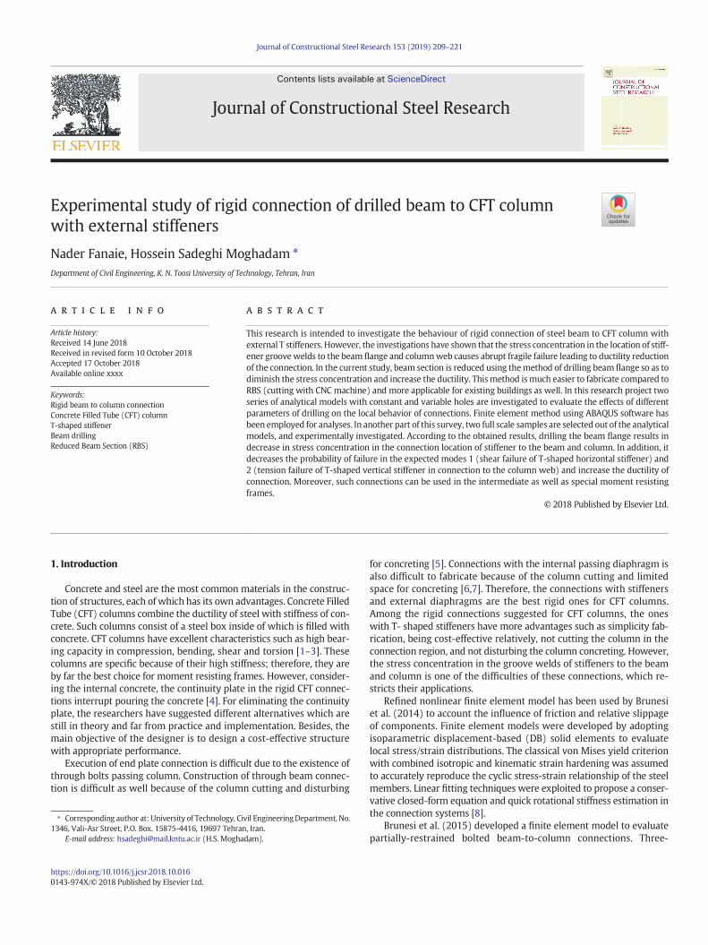
To ensure the accuracy of analytical results, the finite elementmodelhas been verified with cyclic results of TSD120specimen examined byShin et al. [21]. Fig. 1 presents the deformation of the analytical modeland the experimental specimen of Shin et al. research. Moreover, com-parison of analytical and experimental hysteresis curves is shown inFig. 2. As seen, the analytical results are corresponded well with theexperimental ones.
2.3. Connection design
In this study, analytical models are categorized into two sets.Column and beam dimensions are considered constant in each set,and beam is considered stronger in the second set of analytical models.The external T stiffeners are considered to transfer the forces from the
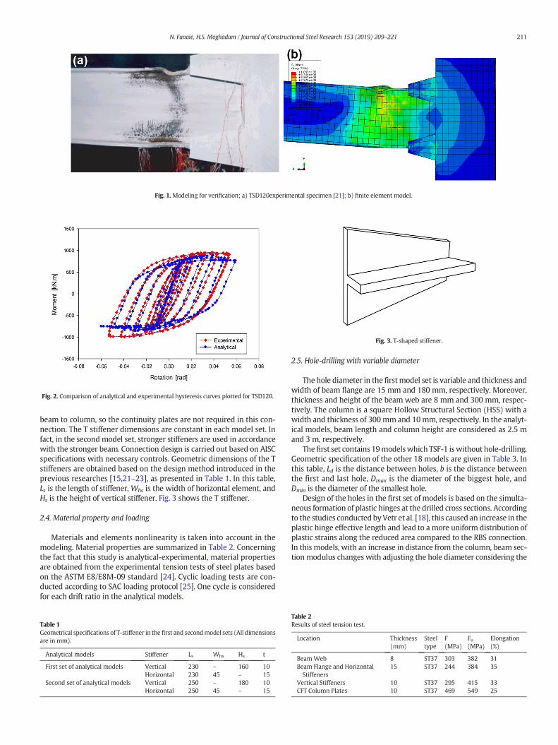
Fig. 1. Modeling for verification; a) TSD120experimental specimen [21]; b) finite element model.
Fig. 2. Comparison of analytical and experimental hysteresis curves plotted for TSD120.
Fig. 3. T-shaped stiffener.
211N. Fanaie, H.S. Moghadam / Journal of Constructional Steel Research 153 (2019) 209–221
beam to column, so the continuity plates are not required in this con-nection. The T stiffener dimensions are constant in each model set. Infact, in the second model set, stronger stiffeners are used in accordancewith the stronger beam. Connection design is carried out based on AISCspecifications with necessary controls. Geometric dimensions of the Tstiffeners are obtained based on the design method introduced in theprevious researches [15,21–23], as presented in Table 1. In this table,Ls is the length of stiffener, Whs is the width of horizontal element, andHs is the height of vertical stiffener. Fig. 3 shows the T stiffener.
2.4. Material property and loading
Materials and elements nonlinearity is taken into account in themodeling. Material properties are summarized in Table 2. Concerningthe fact that this study is analytical-experimental, material propertiesare obtained from the experimental tension tests of steel plates basedon the ASTM E8/E8M-09 standard [24]. Cyclic loading tests are con-ducted according to SAC loading protocol [25]. One cycle is consideredfor each drift ratio in the analytical models.
Table 1Geometrical specifications of T-stiffener in the first and secondmodel sets (All dimensionsare in mm).
Analytical models Stiffener Ls Whs Hs t
First set of analytical models Vertical 230 – 160 10Horizontal 230 45 – 15
Second set of analytical models Vertical 250 – 180 10Horizontal 250 45 – 15
2.5. Hole-drilling with variable diameter
The hole diameter in the firstmodel set is variable and thickness andwidth of beam flange are 15 mm and 180 mm, respectively. Moreover,thickness and height of the beam web are 8 mm and 300 mm, respec-tively. The column is a square Hollow Structural Section (HSS) with awidth and thickness of 300mm and 10mm, respectively. In the analyt-ical models, beam length and column height are considered as 2.5 mand 3 m, respectively.
Thefirst set contains 19modelswhich TSF-1 iswithout hole-drilling.Geometric specification of the other 18 models are given in Table 3. Inthis table, Ld is the distance between holes, b is the distance betweenthe first and last hole, Dmax is the diameter of the biggest hole, andDmin is the diameter of the smallest hole.
Design of the holes in the first set of models is based on the simulta-neous formation of plastic hinges at the drilled cross sections. Accordingto the studies conducted byVetr et al. [18], this caused an increase in theplastic hinge effective length and lead to a more uniform distribution ofplastic strains along the reduced area compared to the RBS connection.In this models, with an increase in distance from the column, beam sec-tion modulus changes with adjusting the hole diameter considering the
Table 2Results of steel tension test.
Location Thickness(mm)
Steeltype
F(MPa)
Fu(MPa)
Elongation(%)
Beam Web 8 ST37 303 382 31Beam Flange and HorizontalStiffeners
15 ST37 244 384 35
Vertical Stiffeners 10 ST37 295 415 33CFT Column Plates 10 ST37 469 549 25
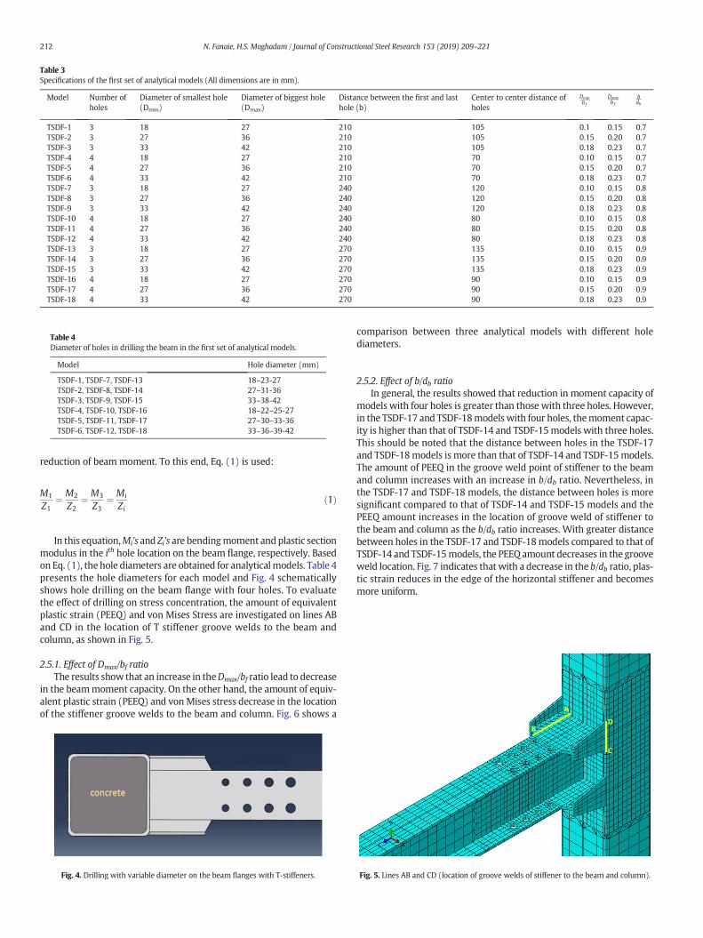
Table 3Specifications of the first set of analytical models (All dimensions are in mm).
Model Number ofholes
Diameter of smallest hole(Dmin)
Diameter of biggest hole(Dmax)
Distance between the first and lasthole (b)
Center to center distance ofholes
Dminb f
Dmaxb f
bdb
TSDF-1 3 18 27 210 105 0.1 0.15 0.7TSDF-2 3 27 36 210 105 0.15 0.20 0.7TSDF-3 3 33 42 210 105 0.18 0.23 0.7TSDF-4 4 18 27 210 70 0.10 0.15 0.7TSDF-5 4 27 36 210 70 0.15 0.20 0.7TSDF-6 4 33 42 210 70 0.18 0.23 0.7TSDF-7 3 18 27 240 120 0.10 0.15 0.8TSDF-8 3 27 36 240 120 0.15 0.20 0.8TSDF-9 3 33 42 240 120 0.18 0.23 0.8TSDF-10 4 18 27 240 80 0.10 0.15 0.8TSDF-11 4 27 36 240 80 0.15 0.20 0.8TSDF-12 4 33 42 240 80 0.18 0.23 0.8TSDF-13 3 18 27 270 135 0.10 0.15 0.9TSDF-14 3 27 36 270 135 0.15 0.20 0.9TSDF-15 3 33 42 270 135 0.18 0.23 0.9TSDF-16 4 18 27 270 90 0.10 0.15 0.9TSDF-17 4 27 36 270 90 0.15 0.20 0.9TSDF-18 4 33 42 270 90 0.18 0.23 0.9
Table 4Diameter of holes in drilling the beam in the first set of analytical models.
Model Hole diameter (mm)
TSDF-1, TSDF-7, TSDF-13 18–23-27TSDF-2, TSDF-8, TSDF-14 27–31-36TSDF-3, TSDF-9, TSDF-15 33–38-42TSDF-4, TSDF-10, TSDF-16 18–22–25-27TSDF-5, TSDF-11, TSDF-17 27–30–33-36TSDF-6, TSDF-12, TSDF-18 33–36–39-42
212 N. Fanaie, H.S. Moghadam / Journal of Constructional Steel Research 153 (2019) 209–221
reduction of beam moment. To this end, Eq. (1) is used:
M1
Z1¼ M2
Z2¼ M3
Z3¼ Mi
Zið1Þ
In this equation,Mi's and Zi's are bendingmoment and plastic sectionmodulus in the ith hole location on the beam flange, respectively. Basedon Eq. (1), the hole diameters are obtained for analyticalmodels. Table 4presents the hole diameters for each model and Fig. 4 schematicallyshows hole drilling on the beam flange with four holes. To evaluatethe effect of drilling on stress concentration, the amount of equivalentplastic strain (PEEQ) and von Mises Stress are investigated on lines ABand CD in the location of T stiffener groove welds to the beam andcolumn, as shown in Fig. 5.
2.5.1. Effect of Dmax/bf ratioThe results show that an increase in theDmax/bf ratio lead to decrease
in the beammoment capacity. On the other hand, the amount of equiv-alent plastic strain (PEEQ) and vonMises stress decrease in the locationof the stiffener groove welds to the beam and column. Fig. 6 shows a
Fig. 4. Drilling with variable diameter on the beam flanges with T-stiffeners.
comparison between three analytical models with different holediameters.
2.5.2. Effect of b/db ratioIn general, the results showed that reduction in moment capacity of
models with four holes is greater than those with three holes. However,in the TSDF-17 and TSDF-18modelswith four holes, themoment capac-ity is higher than that of TSDF-14 and TSDF-15models with three holes.This should be noted that the distance between holes in the TSDF-17and TSDF-18models is more than that of TSDF-14 and TSDF-15models.The amount of PEEQ in the groove weld point of stiffener to the beamand column increases with an increase in b/db ratio. Nevertheless, inthe TSDF-17 and TSDF-18 models, the distance between holes is moresignificant compared to that of TSDF-14 and TSDF-15 models and thePEEQ amount increases in the location of groove weld of stiffener tothe beam and column as the b/db ratio increases. With greater distancebetween holes in the TSDF-17 and TSDF-18models compared to that ofTSDF-14 and TSDF-15models, the PEEQ amount decreases in the grooveweld location. Fig. 7 indicates that with a decrease in the b/db ratio, plas-tic strain reduces in the edge of the horizontal stiffener and becomesmore uniform.
Fig. 5. Lines AB and CD (location of groove welds of stiffener to the beam and column).

Fig. 6. Effect of hole diameter of beam flange in TSDF-4, TSDF-5, and TSDF-6 models; a) Hysteresis curves; b) equivalent plastic strain at the joint of vertical stiffener to column.
Fig. 7. Effect of distance between holes on the plastic strain reduction in the change location of beam cross-section.
213N. Fanaie, H.S. Moghadam / Journal of Constructional Steel Research 153 (2019) 209–221
2.5.3. Overall effect of hole drilling on stress concentrationAs illustrated in Fig. 8, drilling in the beam flange lead to more uni-
form stress and strain in the horizontal stiffener groove weld to thebeam flange. In addition, the stress in the column face has been greatlyreduced by drilling in the beam flange.
2.5.4. Rupture index (RI)To evaluate more accurately the stress concentration in points B and
D at the edge of the horizontal and vertical elements, which are the
Fig. 8. Stress and strain distribution adjacent the stiffeners; a) stress at the connection joint of h
probable points of crack initiation, the rupture index is studied atthese points. Points with higher rupture index aremore possible to frac-ture. The rupture index is calculated using Eq. (2).
RI ¼ εp=εy
exp −1:5σm
σ
� � ð2Þ
orizontal stiffener to beam; b) strain at the connection joint of vertical stiffener to column.

Fig. 9. Rupture index at the horizontal and vertical element edge of stiffener in models; a) b = 210 mm; b) b = 270 mm.
214 N. Fanaie, H.S. Moghadam / Journal of Constructional Steel Research 153 (2019) 209–221
Where, εp is the equivalent plastic strain, εy is the yield strain,σm de-notes hydrostatic stress, and σ is the von Mises equivalent stress. Theratio of σm=σ is called triaxiality ratio. The high triaxiality ratio can sig-nificantly reduce the failure strain of material and limit its ductility.
As shown in Fig. 9, the rupture index has decreased approximately50% in the most models in the critical points using hole drilling. There-fore, the probability of brittle failure and the occurrence of crack is de-creased at the joint of stiffener groove welds to the beam and column.
Fig. 11. Comparison of hysteresis curves of models with hole-drilling and classical RBS.
2.5.5. Comparison with RBSIn Fig. 10, the equivalent plastic strain of classical RBS is compared
with that of TSDF-8 model which has a maximum hole diameter equalto the c parameter of classical RBS. Besides, b parameter of the RBSmodel is selected the same as the distance of the first and last hole inTSDF-8 model.
As seen in Fig. 10 and the diagram of plastic strain in the connectionof stiffeners to the beam and column, it is observed that plastic strain isless in the TSF-1 at the beamaxis compared to classical RBS; however, atthe groove weld points, the plastic strain is much greater than that ofthe RBS model. In the TSDF-8 model, by adjusting the hole diameters,the plastic hinge is shifted away from the stiffeners and plastic strainsare distributedmore uniformly in the beamflange compared to classicalRBS. Thus, it avoided concentrated damage and indicatedmore ductility.
Results showed that the models with variable hole-drilling have afatter hysteresis curve aswell asmore energy dissipation, in comparisonto the classical RBSmodel. Fig. 11 shows the hysteresis curves of TSDF-8model with three holes, TSDF-11 model with four holes, and the RBSmodel with the similar specifications. As it is observed in Fig. 11, themodel with three holes has greater energy dissipation compared tothe model with four holes and both hole-drilled models have greaterenergy dissipation compared to the RBS model.
Fig. 10. Comparison of equivalent plastic strain in the hole-drilling models and RBS in thebeam flange axis at 0.04 rad.
2.6. Hole-drilling with constant diameter
Hole drilling with variable diameters is time consuming and expen-sive for the reason that it needs to replacement of drill bit for each diam-eter in common drilling machines. To better fabrication andeconomization the use of this connection in the building industry, dril-lingwith the constant diameter is proposed. Increasing the number anddiameter of holes, leads to increasing the cost of connection. Besides,drilling big holes will be a multistep process for the thick plates.
As noted above, in the second set of models, the application of dril-ling with constant diameter has been investigated, and in all models,three rows of holes are used. Besides, in the second set of models, stron-ger beam and stiffener are used for making better use of the column ca-pacity. The thickness and width of the beam flange are 15 mm and180 mm, respectively and the thickness and height of the beam webare 8 mm and 320 mm, respectively. Fig. 12 schematically shows thesecond set of analytical models.
Fig. 12. Parameters used in the second set of analytical models.

Table 5Hole drilling characteristics of TSDF-19 and TSDF-20 models.
Model Nomber of holes Dmin Dmax b Dminb f
Dmaxb f
bdb
TSDF-19 3 18 27 210 0.10 0.15 0.65TSDF-20 3 18 27 160 0.10 0.15 0.50
Table 6Hole drilling characteristics of the second set of analytical models.
Model b D Le bdb
Db f
Leb f
TSDF-21 125 22 43 0.35 0.12 0.24TSDF-22 125 27 43 0.35 0.15 0.24TSDF-23 125 32 43 0.35 0.18 0.24TSDF-24 160 22 43 0.45 0.12 0.24TSDF-25 160 27 43 0.45 0.15 0.24TSDF-26 160 32 43 0.45 0.18 0.24TSDF-27 210 22 43 0.6 0.12 0.24TSDF-28 210 27 43 0.6 0.15 0.24TSDF-29 210 32 43 0.6 0.18 0.24TSDF-30 160 27 47 0.45 0.15 0.26TSDF-31 160 27 50 0.45 0.15 0.28
Fig. 13. Comparison of equivalent plastic strain in the location of cross section change formodels with and without hole drilling.
215N. Fanaie, H.S. Moghadam / Journal of Constructional Steel Research 153 (2019) 209–221
Material properties and loading protocol in the second set of modelsare the same as those of the first set. To compare thefirst and the secondset, twomodels with varying holes are considered in the second set. Thediameter of the biggest hole in these twomodels is equal to that of twomodels with the constant diameter. Geometry specifications of themodels mentioned above are presented in Table 5. The diameter ofholes in the TSDF-19 and TSDF-20models is 18mm, 23mm, and27mm.
In thesemodels,D is the hole diameter, b is the distance between thefirst and last hole, and Le is the edge distance, which has been shown inFig. 12. Table 6 shows the characteristics of the other analytical models
Fig. 14. Effect of hole distance on PEEQ index in the cr
with the constant diameter. Besides, TSF-2 is a model without holes inthe second set of analytical models. It should be noted that in theTSDF-21 up to TSDF-29 models, the holes are located in the middle dis-tance of the beam web and flange edge and the TSDF-30 and TSDF-31models are generated to study the effect of edge distance.
2.6.1. Effect of D/bf ratioAs expected,with an increase in theD/bf ratio, the plastic strain is ac-
cumulated around the holes and the strain in the column face decreases.On the other hand, with an increase in hole diameter, moment capacityof connection reduces and the probability of fracture in the holes in-creases. As illustrated in Fig. 13, drilling of the beamflange extremely re-duces the strain concentration at the edges aswell aswhole section andmake it more uniform.
2.6.2. Effect of b/db ratioTo study the effect of hole distance on the reduction of stress concen-
tration, the ratio of b/db is considered. Fig. 14 shows a comparison of thePEEQ index among the second set of models with b/db ratios of 0.35,0.45, and 0.6. In addition, these ratios are compared with those of holedrilling with different diameters. The PEEQ index is the ratio of equiva-lent plastic strain to yield strain, which is obtained from Eq. (3).
PI ¼ PEEQεy
ð3Þ
As shown in Fig. 14, the PEEQ index in the critical points of the con-nection initially decreases with an increase in b/db ratio and then in-creases. Minimum PEEQ index is achieved in almost all models for theb/db ratio of 0.45. The greater distance of holes result in plastic strain ac-cumulation at the closest hole to the column, and the increase in theprobability of rupture at this holes. As it is observed in Fig. 15, in theTSDF-22 model with less hole distance, plastic strain has more uniformdistribution and penetrates well in the beam web cross section. Themaximum PEEQ in this model is less than that of TSDF-28 model.
2.6.3. Overall effect on stress ConcentrationThe results of stress on the second set of models are similar to those
of the first set and reveal that beam flange drilling significantly reducesthe stress concentration at the stiffener horizontal element edge andprevents the occurrence of the brittle failure in this region. Resultsshowed that stress reduces particularly at the column face and becomesmore uniform using hole drilling. Besides, out of plane deformation ofthe column is prevented in this connection. As shown in Fig. 16, beamflange drilling generally results in the reduction of rupture index atpoints B and D, and causes better proportionality between the horizon-tal and vertical elements.
itical points of the stiffener a) point B b) point D.
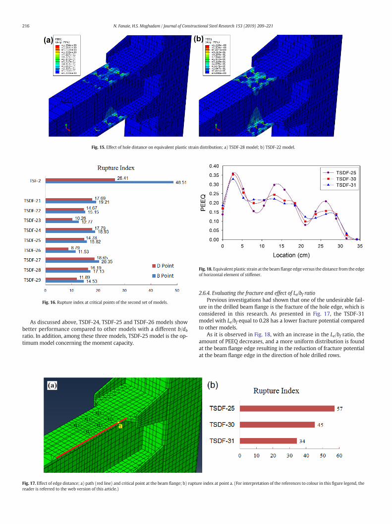
Fig. 15. Effect of hole distance on equivalent plastic strain distribution; a) TSDF-28 model; b) TSDF-22 model.
Fig. 18. Equivalent plastic strain at the beam flange edge versus the distance from the edgeof horizontal element of stiffener.
Fig. 16. Rupture index at critical points of the second set of models.
216 N. Fanaie, H.S. Moghadam / Journal of Constructional Steel Research 153 (2019) 209–221
As discussed above, TSDF-24, TSDF-25 and TSDF-26 models showbetter performance compared to other models with a different b/dbratio. In addition, among these three models, TSDF-25 model is the op-timum model concerning the moment capacity.
Fig. 17. Effect of edge distance; a) path (red line) and critical point at the beam flange; b) ruptureader is referred to the web version of this article.)
2.6.4. Evaluating the fracture and effect of Le/bf ratioPrevious investigations had shown that one of the undesirable fail-
ure in the drilled beam flange is the fracture of the hole edge, which isconsidered in this research. As presented in Fig. 17, the TSDF-31model with Le/bf equal to 0.28 has a lower fracture potential comparedto other models.
As it is observed in Fig. 18, with an increase in the Le/bf ratio, theamount of PEEQ decreases, and a more uniform distribution is foundat the beam flange edge resulting in the reduction of fracture potentialat the beam flange edge in the direction of hole drilled rows.
re index at point a. (For interpretation of the references to colour in this figure legend, the
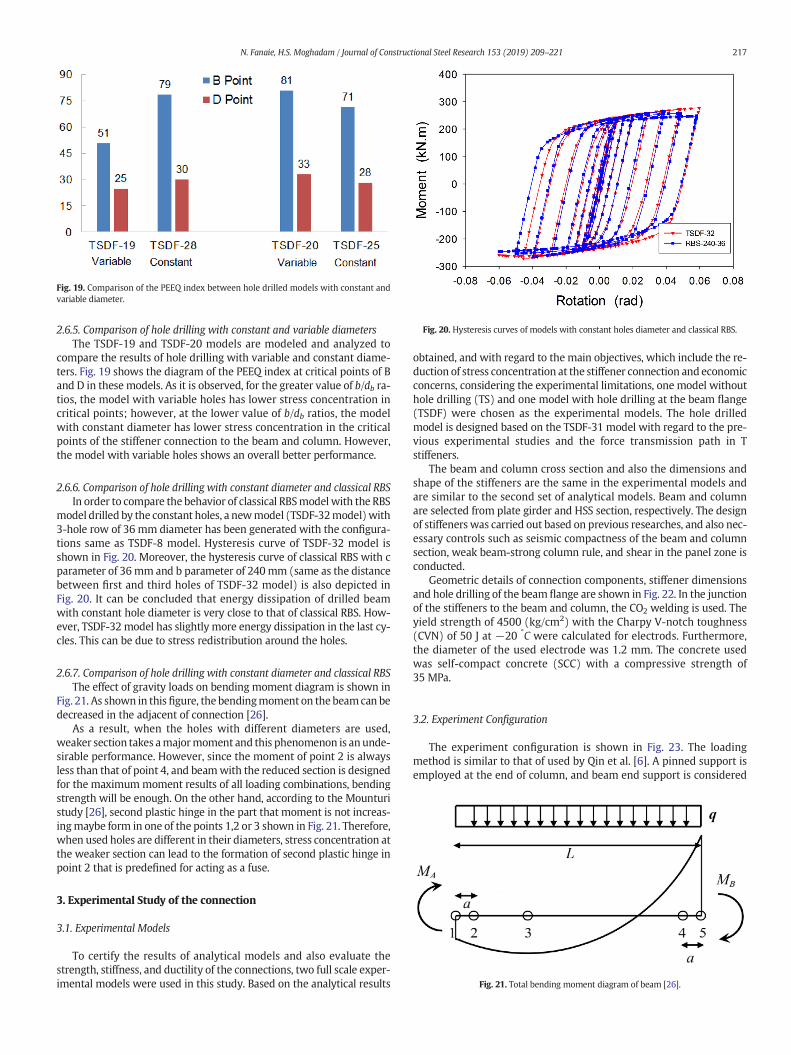
Fig. 19. Comparison of the PEEQ index between hole drilled models with constant andvariable diameter.
Fig. 20. Hysteresis curves of models with constant holes diameter and classical RBS.
Fig. 21. Total bending moment diagram of beam [26].
217N. Fanaie, H.S. Moghadam / Journal of Constructional Steel Research 153 (2019) 209–221
2.6.5. Comparison of hole drilling with constant and variable diametersThe TSDF-19 and TSDF-20 models are modeled and analyzed to
compare the results of hole drilling with variable and constant diame-ters. Fig. 19 shows the diagram of the PEEQ index at critical points of Band D in these models. As it is observed, for the greater value of b/db ra-tios, the model with variable holes has lower stress concentration incritical points; however, at the lower value of b/db ratios, the modelwith constant diameter has lower stress concentration in the criticalpoints of the stiffener connection to the beam and column. However,the model with variable holes shows an overall better performance.
2.6.6. Comparison of hole drilling with constant diameter and classical RBSIn order to compare the behavior of classical RBSmodel with the RBS
model drilled by the constant holes, a newmodel (TSDF-32model)with3-hole row of 36 mm diameter has been generated with the configura-tions same as TSDF-8 model. Hysteresis curve of TSDF-32 model isshown in Fig. 20. Moreover, the hysteresis curve of classical RBS with cparameter of 36mm and b parameter of 240mm (same as the distancebetween first and third holes of TSDF-32 model) is also depicted inFig. 20. It can be concluded that energy dissipation of drilled beamwith constant hole diameter is very close to that of classical RBS. How-ever, TSDF-32 model has slightly more energy dissipation in the last cy-cles. This can be due to stress redistribution around the holes.
2.6.7. Comparison of hole drilling with constant diameter and classical RBSThe effect of gravity loads on bending moment diagram is shown in
Fig. 21. As shown in thisfigure, the bendingmoment on the beamcan bedecreased in the adjacent of connection [26].
As a result, when the holes with different diameters are used,weaker section takes amajormoment and this phenomenon is anunde-sirable performance. However, since the moment of point 2 is alwaysless than that of point 4, and beamwith the reduced section is designedfor the maximummoment results of all loading combinations, bendingstrength will be enough. On the other hand, according to the Mounturistudy [26], second plastic hinge in the part that moment is not increas-ingmaybe form in one of the points 1,2 or 3 shown in Fig. 21. Therefore,when used holes are different in their diameters, stress concentration atthe weaker section can lead to the formation of second plastic hinge inpoint 2 that is predefined for acting as a fuse.
3. Experimental Study of the connection
3.1. Experimental Models
To certify the results of analytical models and also evaluate thestrength, stiffness, and ductility of the connections, two full scale exper-imental models were used in this study. Based on the analytical results
obtained, and with regard to the main objectives, which include the re-duction of stress concentration at the stiffener connection and economicconcerns, considering the experimental limitations, one model withouthole drilling (TS) and one model with hole drilling at the beam flange(TSDF) were chosen as the experimental models. The hole drilledmodel is designed based on the TSDF-31 model with regard to the pre-vious experimental studies and the force transmission path in Tstiffeners.
The beam and column cross section and also the dimensions andshape of the stiffeners are the same in the experimental models andare similar to the second set of analytical models. Beam and columnare selected from plate girder and HSS section, respectively. The designof stiffeners was carried out based on previous researches, and also nec-essary controls such as seismic compactness of the beam and columnsection, weak beam-strong column rule, and shear in the panel zone isconducted.
Geometric details of connection components, stiffener dimensionsand hole drilling of the beam flange are shown in Fig. 22. In the junctionof the stiffeners to the beam and column, the CO2 welding is used. Theyield strength of 4500 (kg/cm2) with the Charpy V-notch toughness(CVN) of 50 J at −20 °C were calculated for electrods. Furthermore,the diameter of the used electrode was 1.2 mm. The concrete usedwas self-compact concrete (SCC) with a compressive strength of35 MPa.
3.2. Experiment Configuration
The experiment configuration is shown in Fig. 23. The loadingmethod is similar to that of used by Qin et al. [6]. A pinned support isemployed at the end of column, and beam end support is considered
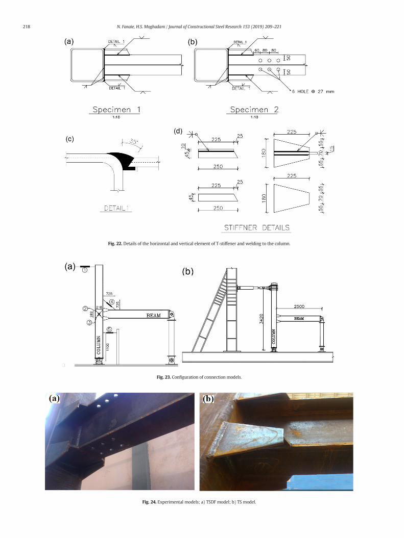
Fig. 22. Details of the horizontal and vertical element of T-stiffener and welding to the column.
Fig. 23. Configuration of connection models.
Fig. 24. Experimental models; a) TSDF model; b) TS model.
218 N. Fanaie, H.S. Moghadam / Journal of Constructional Steel Research 153 (2019) 209–221
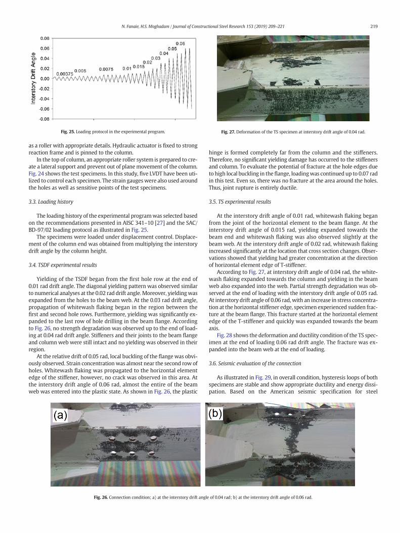
Fig. 25. Loading protocol in the experimental program. Fig. 27. Deformation of the TS specimen at interstory drift angle of 0.04 rad.
219N. Fanaie, H.S. Moghadam / Journal of Constructional Steel Research 153 (2019) 209–221
as a roller with appropriate details. Hydraulic actuator is fixed to strongreaction frame and is pinned to the column.
In the top of column, an appropriate roller system is prepared to cre-ate a lateral support and prevent out of planemovement of the column.Fig. 24 shows the test specimens. In this study, five LVDT have been uti-lized to control each specimen. The strain gaugeswere also used aroundthe holes as well as sensitive points of the test specimens.
3.3. Loading history
The loading history of the experimental programwas selected basedon the recommendations presented in AISC 341–10 [27] and the SAC/BD-97/02 loading protocol as illustrated in Fig. 25.
The specimens were loaded under displacement control. Displace-ment of the column end was obtained from multiplying the interstorydrift angle by the column height.
3.4. TSDF experimental results
Yielding of the TSDF began from the first hole row at the end of0.01 rad drift angle. The diagonal yielding pattern was observed similarto numerical analyses at the 0.02 rad drift angle. Moreover, yieldingwasexpanded from the holes to the beam web. At the 0.03 rad drift angle,propagation of whitewash flaking began in the region between thefirst and second hole rows. Furthermore, yielding was significantly ex-panded to the last row of hole drilling in the beam flange. Accordingto Fig. 26, no strength degradation was observed up to the end of load-ing at 0.04 rad drift angle. Stiffeners and their joints to the beam flangeand columnweb were still intact and no yielding was observed in theirregion.
At the relative drift of 0.05 rad, local buckling of the flangewas obvi-ously observed. Strain concentrationwas almost near the second row ofholes. Whitewash flaking was propagated to the horizontal elementedge of the stiffener, however, no crack was observed in this area. Atthe interstory drift angle of 0.06 rad, almost the entire of the beamweb was entered into the plastic state. As shown in Fig. 26, the plastic
Fig. 26. Connection condition; a) at the interstory drift angle
hinge is formed completely far from the column and the stiffeners.Therefore, no significant yielding damage has occurred to the stiffenersand column. To evaluate the potential of fracture at the hole edges dueto high local buckling in theflange, loadingwas continued up to 0.07 radin this test. Even so, there was no fracture at the area around the holes.Thus, joint rupture is entirely ductile.
3.5. TS experimental results
At the interstory drift angle of 0.01 rad, whitewash flaking beganfrom the joint of the horizontal element to the beam flange. At theinterstory drift angle of 0.015 rad, yielding expanded towards thebeam end and whitewash flaking was also observed slightly at thebeam web. At the interstory drift angle of 0.02 rad, whitewash flakingincreased significantly at the location that cross section changes. Obser-vations showed that yielding had greater concentration at the directionof horizontal element edge of T-stiffener.
According to Fig. 27, at interstory drift angle of 0.04 rad, the white-wash flaking expanded towards the column and yielding in the beamweb also expanded into the web. Partial strength degradation was ob-served at the end of loading with the interstory drift angle of 0.05 rad.At interstory drift angle of 0.06 rad, with an increase in stress concentra-tion at the horizontal stiffener edge, specimen experienced sudden frac-ture at the beam flange. This fracture started at the horizontal elementedge of the T-stiffener and quickly was expanded towards the beamaxis.
Fig. 28 shows the deformation and ductility condition of the TS spec-imen at the end of loading 0.06 rad drift angle. The fracture was ex-panded into the beam web at the end of loading.
3.6. Seismic evaluation of the connection
As illustrated in Fig. 29, in overall condition, hysteresis loops of bothspecimens are stable and show appropriate ductility and energy dissi-pation. Based on the American seismic specification for steel
of 0.04 rad; b) at the interstory drift angle of 0.06 rad.

Fig. 29. Hysteresis curves for test specimens; a) TSDF; b) TS.
Fig. 28. Deformation of the TS specimen at interstory drift angle of 0.06 rad.
220 N. Fanaie, H.S. Moghadam / Journal of Constructional Steel Research 153 (2019) 209–221
construction (AISC 318–11), an interstory drift angle of at least 0.04 radmust be sustained by the connection and the measured flexural resis-tance of the connection shall equal to at least 80% of the plastic momentcapacity. Then according to AISC, both specimens are accepted for spe-cial moment resisting frames.
Concerning the fact that the TS specimen had severe stress concen-tration and sudden fracture has occurred in the beam flange at theend of second cycle of loading with interstory drift angle of 0.06 radand possibly not reliable to undergo the gravity loads. Therefore, thistype of connection is not recommended without reducing the beamflange. A comparison between the hysteresis curves of TSDF and
Fig. 30. Comparison of TS and TSDF test specimens.
TS test specimens in Fig. 30 shows that the stiffness degradation is ap-proximately identical in both specimens. Moreover, the strength degra-dation of TSDF is gradual while in the TS specimen it occurs almostsuddenly. However, the final strength degradation of TS is almostequal to the TSDF specimen.
4. Conclusion
The most important results obtained from this study are outlinedbelow:
1- The rupture index at points with themost stress concentration in fi-nite element analysis decreased over 50% for TSDF-23, TSDF 26 andTSDF 29 in the specimens with constant hole diameter.
2- In the analytical models with variable holes, the equivalent plasticstrain (PEEQ) at the joint of stiffener groove welds to beam and col-umn increases with the increase in b/db ratio. However, changes inthe b/db ratio do not have a significant effect on the overall behaviorof connection and the hysteresis curve.
3- With an increase of b/db ratio in hole drilling with a constant diame-ter, the rupture index increases at critical points, which is more in-tense for b/db ratios greater than 0.45. While, The PEEQ index forthe b/db ratio of 0.45 has its least amount and in the models withconstant hole diameter, it is less than its value in the variable hole di-ameter models. In this study, it is recommended that the b/db rangebe considered equal to 0.4 to 0.5.
4- In the test specimens, with an increase in the ratio of Le/bf to 0.28, thehole edge fracturewas prevented. TSDF specimenwas loaded up to arelative drift of 0.07 rad and no fracture was observed at the holeedge or the joint of the stiffener to beam and column.

221N. Fanaie, H.S. Moghadam / Journal of Constructional Steel Research 153 (2019) 209–221
5- With a decrease in the Dmin/bf ratio in the models, the probability ofbrittle fracture increases in the location of change the cross section.Therefore, theminimumamount of 0.12 in the design of hole drillingwith various diameters is proposed.
6- With an increase in hole diameters, stress concentration of T-stiffener groove welds and beam moment capacity decreases. It issuggested that the maximum Dmax/bf ratio be limited to 0.2.
7- A comparison of drilled specimens with classical RBS shows that inthe first set of drilled specimens with variable diameters, plasticstrain compared to RBS is expanded in a more significant length ofthe beam and strain accumulation is prevented at a point. Further-more, in these models, local buckling in the beam flange is delayedwhich cause an increase in the area under the hysteresis curve, en-ergy dissipation and beam stability. However, considering the effectof gravity loads on beam, this result is possibly different and stress,as well as strain, is concentrated in a section. Even so, as explainedin this study, this connection has enough strength to sustain againstthe lateral and gravity loads.
8- Sudden rupture of the TS specimen in the second cycle of 0.06 raddrift angle and flange fracture at this level, compared with theTSDF specimen indicated that hole drilling of the beam flange canbe an efficient method for increasing ductility, reducing stressconcentration, preventing brittle fracture in this connection andavoiding the rupture in modes 1 and 2 in these connections.
9- Evaluating the PEEQ, TR and IR indices in the analytical and experi-mental models reveals that these indices can be an excellent crite-rion for predicting fracture points in these connections.
Acknowledgements
We would like to thank the Neka Foolad Machine Company and itsCEO, Eng. Latifi for his financial support in this research project, andgranting permission to use the company's equipment.
References
[1] W.L.A. De Oliveira, S.D. Nardin, De Cresce El Debs ALH, Evaluation of passive confine-ment in CFT columns, J. Constr. Steel Res. 66 (2010) 487–495.
[2] L.H. Han, G.H. Yao, Z. Tao, Performance of concrete-filled thin-walled steel tubesunder pure torsion, Thin-Walled Struct. 45 (2007) 24–36.
[3] E. Eiichi Inai, A. Mukai, M. Kai, H. Tokinoya, T. Fukumoto, K. Mori, Behavior ofConcrete-Filled Steel Tube Beam Columns, J. Struct. Eng. 130 (2) (2004) 189–202.
[4] Y.M. Alostaz, P. Shneider, Connections to Concrete-Filled Steel Tubes, EleventhWorld Conference on Earthquake Engineering (1996) (Paper No. 748).
[5] I.S. Sheet, U. Gunasekaran, G.A. MacRae, Experimental investigation of CFT column tosteel beam connections under cyclic loading, J. Constr. Steel Res. 86 (2013) 167–182.
View publication statsView publication stats
[6] Y. Qin, Z. Chen, Q. Yang, K. Shang, Experimental seismic behavior of through-diaphragm connections to concrete-filled rectangular steel tubular columns, J.Constr. Steel Res. 93 (2014) 32–43.
[7] Y. Yu, Z. Chen, X. Wang, Effect of column flange flexibility on WF-beam to rectangu-lar CFT column connections, J. Constr. Steel Res. 106 (2015) 184–197.
[8] E. Brunesi, R. Nascimbene, G.A. Rassati, Response of partially-restrained boltedbeam-to column connections under cyclic loads, J. Constr. Steel Res. 97 (2014)24–38.
[9] E. Brunesi, R. Nascimbene, G.A. Rassati, Seismic response of MRFs with partially-restrained bolted beam-to-column connections through FE analyses, J. Constr.Steel Res. 107 (2015) 37–49.
[10] R. Nascimbene, An arbitrary cross section, locking free shear-flexible curved beamfinite element, Int. J. Comput. Meth. Eng. Sci. Mech. 14 (2013) 90–103.
[11] R. Nascimbene, Towards non-standard numerical modeling of thin-shell structures:geometrically Linear Formulation, Int. J. Comput. Methods Eng. Sci. Mech. 15 (2014)126–141.
[12] C.H. Kang, K.J. Shin, Y.S. Oh, T.S. Moon, Hysteresis behavior of CFT column to H-beamconnections with external T stiffener and penetrate elements, Eng. Struct. 23 (2001)1194–1201.
[13] K.J. Shin, Y.J. Kim, Y.S. Oh, T.S. Moon, Behavior of welded CFT column to H-beam con-nections with external stiffeners, Eng. Struct. 26 (2004) 1877–1887.
[14] Y.J. Kim, K.J. Shin, W.J. Kim, Effect of stiffener details on behavior of CFT column tobeam connections, Steel Structures 64 (2008) 119–133.
[15] C.H. Kang, Y.J. Kim, K.J. Shin, Y.S. Oh, Experimental Investigation of Composite Mo-ment Connections with External Stiffeners, Adv. Struct. Eng. 16 (10) (2013)1683–1700.
[16] K.C. Tsai, C.Y. Chen, Performance of ductile steel beam-column moment connec-tions, Eleventh World Conference on Earthquake Engineering (1996) (Paper No.405).
[17] S.J. Lee, S.E. Han, N.O.H. Se, S.W. Shin, Deformation Capacity of Reduced BeamSection Moment Connection by Staggered Holes, Proceedings of the InternationalConference on Sustainable Building Asia 2007, pp. 1067–1072.
[18] M.G. Vetr, M. Miri, A. Haddad, Seismic Behavior of a New Reduced Beam SectionConnection by Drilled Holes Arrangement (RBS-DHA) on the Beam Flanges ThroughExperimental Studies. 15 WCEE LISBOA, 2012.
[19] S. Kazerani, N. Fanaie, S. Soroushnia, Seismic behavior of drilled beam section inmo-ment connections, Num. Methods Civil Eng. 1 (2) (2014) 21–28.
[20] K.A.S. Susantha, H.B. Ge, T. Usami, A capacity prediction procedure for concrete filledsteel columns, J. Earthq. Eng. 5 (4) (2001) 483–520.
[21] K.J. Shin, Y.J. Kim, Y.S. Oh, Seismic behaviour of composite concrete-filled tubecolumn-to-beam moment connections, J. Constr. Steel Res. 64 (2008) 118–127.
[22] M.S. Ghobadi, M. Ghassemieh, A. Mazroi, A. Abolmaali, Seismic performance of duc-tile welded connections using T-stiffener, J. Constr. Steel Res. 65 (4) (2009)766–775.
[23] T.S. Moon, Y.S. Oh, K.J. Shin, C.H. Kang, Hysteresis behavior of CFT column to H-beamconnections with external T-stiffeners and penetrated elements, Eng. Struct. 23 (9)(2001) 1194–1201.
[24] ASTM/E8, Standard Test Methods for Tension Testing of Metallic Materials, 2004.[25] SAC. SAC/BD-97/02 Version 1.1, Protocol for fabrication, inspection, testing, and doc-
umentation of beam-column connection tests and other specimens, Sacramento(CA): SAC Joint Venture, 1997.
[26] R. Montuori, The influence of gravity loads on the seismic design of RBS connections,Open Construct. Build. Technol. J. 8 (2014) 248–261.
[27] AISC, ANSI/AISC 341-10. Seismic Provisions for Structural Steel Buildings, AmericanInstitute of Steel Construction, Inc., Chicago, IL, 2010.