experimental studies of vortex disconnection and connection at a
TRANSCRIPT

J . Fluid Mech. (1996). col. 32 I . p p . 59-86 Copyright 0 1996 Cambridge University Press
59
Experimental studies of vortex disconnection and connection at a free surface
By MORTEZA GHARIB A N D A L E X A N D E R W E I G A N D Graduate Aeronautical Laboratories, California tnstitute of Technology, Pasadena,
CA 91125, USA
(Received 14 August 1995 and in revised form 22 March 1996)
An experimental study is presented that examines the interaction of a vortex ring with a free surface. The main objective of this study is to identify the physical mechanisms that are responsible for the self-disconnection of vortex filaments in the near-surface region and the subsequent connection of disconnected vortex elements to the free surface. The understanding of those mechanisms is essential for the identification and estimation of the appropriate spatial and temporal scales of the disconnection and connection process. In this regard, the velocity and vorticity fields of an obliquely approaching laminar vortex ring with a Reynolds number of 1150 were mapped by using Digital Particle Image Velocimetry (DPIV). The evolution of the near-surface vorticity field indicates that the connection process starts in the side regions of the approaching vortex ring where surface-normal vorticity already exists in the bulk. A local strain rate analysis was conducted to support this conclusion. Disconnection in the near-surface tip region of the vortex ring occurs because of the removal of surface- parallel vorticity by the viscous flux of vorticity through the surface. Temporal and spatial mapping of the vorticity field at the surface and in the perpendicular plane of symmetry shows that the viscous flux is balanced by a local deceleration of the flow at the surface. I t is found that the observed timescales of the disconnection and connection process scale with the near-surface vorticity gradient rather than with the core diameter of the vortex ring.
1. Introduction Surface shear flows, such as the wake of an island or a ship, and flows generated by
under-surface current present intriguing features. The persistence of some of the observed features are uniquely puzzling in that they do not obey any known decay laws of fully submerged flows. Typical ship wakes and surface currents in the ocean possess Reynolds numbers in excess of lo8 which, in combination with the complex nature of these turbulent flows, makes their full simulation difficult, if not impossible, to perform. One interesting feature during the formation and evolution of surface shear flows is the dominant role of sub-surface vortices and large-scale vortical structures. In this regard, studies of the free-surface interaction of vortices such a vortex rings and vortex pairs are critical in the understanding of the main features of surface shear flows. Therefore, the research scene in free-surface turbulence is dominated by efforts that focus on the understanding of the interaction of elemental vortex flows with free surfaces.
Vortex rings and vortex pairs have received much attention as the primary constituents of any generic shear flow. The problem of a vortex ring or a vortex pair approaching a boundary with a free-slip or no-slip condition (whether it is solid or

60 M . Gharib and A . Weigand
deformable) is challenging, since it involves unsteady three-dimensional vortex interactions. The pioneering work of Sarpkaya & Henderson (1989, and subsequent important studies of Ohring & Lugt (1991) and Dommermuth (1992) on the vortex- pair problem, and the work by Kwon (1989) and Bernal & Kwon (1989) on the vortex- ring problem opened a new era in our understanding of vortex/free-surface interactions. In those studies, vortex trajectories and surface signatures such as scars and striations have been investigated extensively. However, the connection of vortex filaments to a free surface had not received serious attention until the experiments of Bernal & Kwon (1989) and the analytical studies of Lugt (1987) who elegantly explained the proper kinematic conditions at the surface. Bernal & Kwon made the first clear demonstration of the early stages that a vortex ring undergoes as it rises toward a free surface. Their observations raised many important fundamental questions regarding the interaction with the free surface which is drastically different from the case of a vortex ring interacting obliquely with a solid wall (Lim 1989; Chu, Wang & Hseih 1993). However, Bernal & Kwon did not clarify the issue of whether the apex of the vortex ring simply tilts and connects to the free surface, or whether it disconnects and subsequently connects its free ends to the surface. In their experiments, the effect of the angle of approach was found to be significant regarding the connection timescale, while the Reynolds number of the vortex ring did not play an important role. They argued that the viscous diffusion timescale overpredicts the connection timescale and, therefore, assumed an inviscid scaling based on the circulation and core diameter of the vortex ring. However, the latter resulted in the underprediction of the connection timescale (see figure 14 of Kwon 1989). Therefore, the main question is: What are the proper physical parameters that describe the connection timescale for a given angle of approach of a vortex ring?
In this paper, we focus on the mechanisms that lead to the disconnection and surface connection of a laminar vortex ring as it approaches the free surface at a shallow angle. Our objective is to present a clear picture of the stages that are involved in the early disconnection and subsequent connection process by using results of velocity- and vorticity-field measurements. Obviously, as has been shown by Bernal et al. (1989), the physical state of the free surface is a point of concern in terms of the presence of surfactants. We address these concerns by conducting two sets of experiments where a vortex ring approaches a very clean and a semi-clean water surface. In our investigations, Digital Particle Image Velocimetry (DPIV) was employed to map the spatial and temporal evolution of the velocity and vorticity fields during the interaction with the free surface. The mapping process was carried out (in some cases simultaneously) very close to the free surface and at various two-dimensional cross- sections in the flow.
2. Experimental setup and procedures Experiments were conducted in a water tank using a mechanical vortex-ring
generator. As the schematic in figure 1 shows, vortex rings of diameter D, circulation T, and propagation velocity U, were generated by a piston that pushes fluid out of a sharp-edged cylindrical nozzle with an inner orifice diameter of Do = 3.0 cm. The non- deformed water surface coincides with the (x, z)-plane where the positive z-axis points toward the reader. The centreline of the vortex-ring generator (i.e. the x’-axis) is inclined to the water surface at an angle a, and the origin x’ = 0 is located at x = 0 and y = -h, where h designates the submergence depth of the generator.
To minimize surface-contamination effects and surface-tension differences between

Vortex disconnection and connection at a , free surface 61
Free surface yt x
FIGURE 1. General schematic of the experimental setup.
the water in the bulk and at the surface, careful steps were taken to keep the water and its surface clean. Besides using de-ionized water and working in a clean environment (i.e. in a class 100000 clean room, wearing non-contaminating gloves, cleaning all parts in contact with water using ethyl alcohol, and operating a UV filter to prevent bacterial growth in the water), a constantly operating skimmer and a vacuum-operated suction device were using to remove the aging water surface. Surface-tension measurements were performed before and after each experimental run using a ring tensiometer (Fisher Surface Tensiomat, Mod. 21).
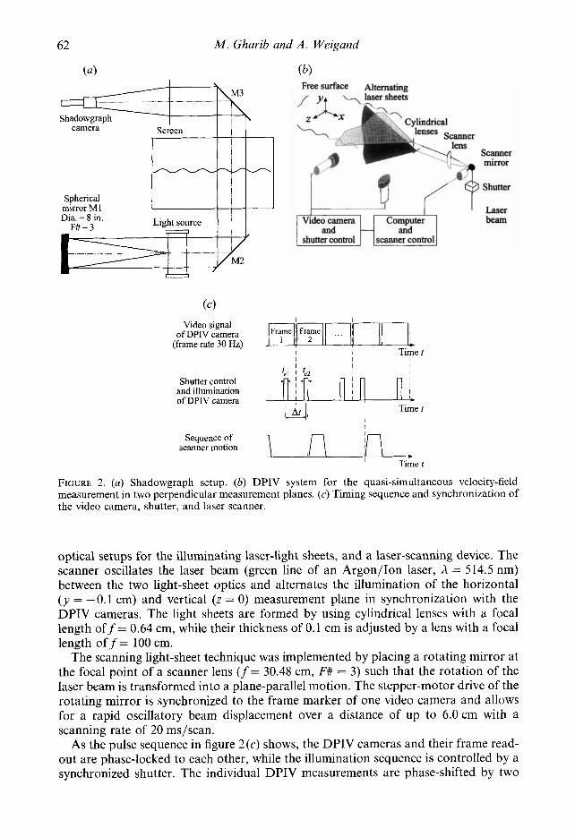
An IBM PC provided precise timing and synchronization of different events (time resolution better than s) including vortex-ring generation, dye injection for flow visualization, and initialization of measurement processes. As figure 2 (a) shows, an off- axis shadowgraph setup with a parallel beam diameter of 8 in. was used for the visualization of the vortex-ring/free-surface interaction and the resulting surface- deformation fields.
Regarding Digital Particle Image Velocimetry (DPIV), only those aspects of the measurement technique that are relevant to the present work are described in this paper. (For a more detailed discussion, the reader is referred to Willert & Gharib 1991 .) DPIV measures the two-dimensional displacement-vector field of particles that are suspended in the flow and illuminated by a thin, pulsed sheet of laser light. A video camera is positioned normal to the illuminated measurement plane and records a sequence of particle-image fields. The exposure times and time difference between successive image exposures are synchronized and controlled by a camera controller and a shutter. The latter prevents streaking particle images and limits the maximum displacement of particles in the imaging plane. The recorded image sequence is stored on an analog video disk and subsequently digitized by a frame grabber. By cross-correlating spatial sub-samples (windows) of two successive video images, the average local displacement vector of the particles contained in the correlation window is estimated. Moving the correlation window over the entire image, the displacement-vector field is obtained. The latter is divided by the time difference between two successive image exposures yielding the velocity-vector field.
In the present experiments, we used single and quasi-simultaneous double-plane DPIV measurements in order to map the velocity fields close to the free surface and in the plane of symmetry z = 0. Figure 2(b) shows the experimental setup of the quasi- simultaneous measurement technique that uses two separate DPIV cameras, two
62 M . Gharib and A . Weigand
(a) (Q
Frame ~
1 1 2 of DPIV camera
Free surface Alternating
camera
Scanner mirror
Shutter
Laser beam
Frame _ _ _ I I I
I I
Shutter control and illumination of DPIV camera n r r ni
Time t
I I I I I
I I I 1 I I
Sequence of I
scanner motion *
Time t
FIGURE 2. (a) Shadowgraph setup. (b) DPIV system for the quasi-simultaneous velocity-field measurement in two perpendicular measurement planes. (c) Timing sequence and synchronization of the video camera, shutter, and laser scanner.
optical setups for the illuminating laser-light sheets, and a laser-scanning device. The scanner oscillates the laser beam (green line of an Argon/Ion laser, h = 514.5 nm) between the two light-sheet optics and alternates the illumination of the horizontal ( y = -0.1 cm) and vertical ( z = 0) measurement plane in synchronization with the DPIV cameras. The light sheets are formed by using cylindrical lenses with a focal length of f= 0.64 cm, while their thickness of 0.1 cm is adjusted by a lens with a focal length o f f= 100 cm.
The scanning light-sheet technique was implemented by placing a rotating mirror at the focal point of a scanner lens ( f = 30.48 cm, F# = 3) such that the rotation of the laser beam is transformed into a plane-parallel motion. The stepper-motor drive of the rotating mirror is synchronized to the frame marker of one video camera and allows for a rapid oscillatory beam displacement over a distance of up to 6.0cm with a scanning rate of 20 ms/scan.
As the pulse sequence in figure 2 (c) shows, the DPIV cameras and their frame read- out are phase-locked to each other, while the illumination sequence is controlled by a synchronized shutter. The individual DPIV measurements are phase-shifted by two

Vortex disconizection und connection ut a free surface 63
video frames (66 ms) resulting in the quasi-simultaneous and alternating measurement of the velocity fields in the horizontal and vertical plane.
In the DPIV measurements, neutrally buoyant silver-coated glass spheres with an average diameter of 14 k 5 pm were used as seeding particles. The exposure times and time difference between exposures of the DPIV cameras were tPl = teZ = 4 x lop3 s and At = 7 x lo-" s, respectively. The video images were digitized with a resolution of 768 x 480 pixels, and processed with a window wide of 32 x 32 pixels and a step size of 8 x 8 pixels (75 YO window overlap). The data processing results in a field measurement of 96 x 60 velocity vectors and, for a typical field of view of 11 x 8 cm, in a spatial wavelength resolution of 0.46 x 0.54 cm. Since the location of the cross-correlation peak can be resolved with a sub-pixel accuracy of approximately 0.01 pixel (Willert & Gharib 1991) the maximum uncertainty based on the local velocity and vorticity magnitude is C 1 YO and -t 3 %, respectively.
3. Results 3. I . Initial conditions
Prior to the investigation of the free-surface interaction, the physical properties of the laminar vortex rings were investigated in the fully submerged case by means of flow visualization and Digital Particle Image Velocimetry (Weigand & Gharib 1995). In the present work the oblique interaction with the free surface was studied by using vortex rings with a diameter of D = 3.0 cm and a Reynolds number of Re = 1150 where the Reynolds number is defined by the ratio of the circulation r a n d the kinematic viscosity 1' (i.e. Re = T/v). As a result of the DPIV measurements, the core size of the vortex rings was found to be relatively large with an initial core to vortex-ring diameter ratio of approximately 0.6. In all flow cases, the submergence depth and inclination angle of the vortex-ring generator are h = 3.0 cm (one nozzle diameter) and cx = 7", respectively. The resulting Froude and Weber numbers are Fr = r / ( g D 3 ) ' " z 0.07 and W e = p P / ( n D ) z 0.6, using the measured surface tension of D.1.-water v = 72.120.5 dyn cm-' (1 dyn = lo-" N), the density of water p = 1000 kg m-3, and the gravitational acceleration g = 9.81 m s-l. In order to be able to map the velocity field close to the free surface, the Reynolds and Froude numbers were chosen to be relatively small such that only small surface deformations are generated (i.e. deformations of the order of magnitude of the laser-sheet thickness).
In the following sections, the results of two distinct flow cases are presented. In the first, referred to as the 'clean' case, extraordinary care was taken to keep the water surface clean and uncontaminated, while, in the second, referred to as the ' semi-clean' case, slight surface contamination was present. However, surface-tension meas- urements using a ring tensiometer with a nominal accuracy of CO.1 dyn cm-l and an experimentally determined repeatability of C0.5 dyn cm-l did not reveal the degree of contamination. Therefore, the distinction between the clean and semi-clean flow cases is based on differences in their surface-interaction and connection behaviour, and on differences in the formation of Reynolds ridges (Scott 1982). In contrast to the semi- clean case, the formation of Reynolds ridges due to surface-tension differences was not observed in the clean case.
3.2. Results of flow risua/izurion To obtain a qualitative understanding of the flow at the free surface, the shadowgraph technique was used (Weigand 1995). In order to improve the quality of the shadowgraph images, the visualization experiments were conducted at higher Froude

M . Ghavih and A . Weigand
FIGURE 3(a). For caption see facing page

Vortex tlisconnection and c'onnection ut a f r e t S ~ N ~ U C P 65
FIGURE 3. Shadowgraph images of thc surface deformation during the vortex-ring interaction with (a) clean surface, ( h ) contaminated surface. Re = 5000 and Fr = 0.2 (direction of the flow is from left to right. all frames are the same scale, and time is indicated in each frame).

66 M . Gharib and A . Weigand
numbers with Fr = 0.2. However, the DPIV measurements were conducted with the aforementioned Froude number of Fr zz 0.07 in order to avoid strong surface deformations.
As the shadowgraph sequence in figure 3(a) indicates, the clean interaction is initially characterized by an elliptical surface deformation followed by the appearance of two distinct and round surface depressions that enlarge with time. As was reported by Bernal & Kwon (1989), later stages involve the fold-up and splitting of the lower part of the vortex ring which results in the formation of two half-vortex rings that are connected to the surface. Similar to the observations of Bernal & Kwon, the symmetric surface depressions appear to be associated with the connection of the vortex ring, i.e. the opening of the upper portion of the vortex-ring. In this paper, we focus on the early but important stages of the vortex-ring connection. In order to relate these observations to the connection process, the evolution of the velocity and vorticity fields as the surface and in planes normal to it are discussed next.
3 . 3 . Free-surface velocity field In the clean and semi-clean cases, DPIV provided many velocity fields of the vortex ring during the course of its interaction with the free surface. This enabled us to identify some important milestones in the interaction process which are referred to as stages. Based on the evolution of the surface-velocity field, those stages were observed to be common to both clean and semi-clean cases. However, the reader should be cautioned that, in the case of extremely contaminated surfaces with more than 5dyncm-' difference in surface tension, the vortex connection and the observed stages might not occur (Gharib 1994; Willert & Gharib 1995).
An example of such a highly contaminated surface is shown in the shadowgraph images of figure 3 (b) . In this case, the observed stages are drastically different from the flow-visualization results of the clean case. In comparison to figure 3(a) the most obvious difference evolves during the final stages where the surface connection of the lower part of the vortex ring and the formation of two symmetric half-vortex rings were not observed.
Stage I in figure 4 shows the initial surface motion induced by the irrotational velocity field of the vortex ring. This early stage is characterized by the appearance of two stagnation regions (marked by S1 and S2) that are located on the centreline at x1 = 8.3 cm and x, z 6.1 cm, respectively. The flow in the centre region accelerates from S1 in the negative x-direction and decelerates towards S2. Between Stages I and 111, the surface-flow pattern resembles that of a doublet. This pattern results from the oblique approach of the vortex ring toward the surface and is a manifestation of the induced velocity field of the small upper arc-portion of the vortex ring. While S2 moves downstream towards S1, the two stagnation regions merge and form a larger region with an overall reduction in velocity magnitude.
From Stage I11 to IV, a qualitative change in the flow behaviour occurs in the form of a flow reversal between S1 and S2. The flow reversal changes the doublet into a dipole pattern by Stage IV. Subsequently, a strong forward current on the centre-line enhances the dipole pattern which results in the appearance of two counter-rotating elongated regions at Stage V. Stage VI shows the formation of two identifiable circular surface-flow patterns and the completion of the connection process.
Figure 5 shows simultaneous velocity-vector fields for the clean case, obtained in the plane of symmetry z = 0 and at the free surface. The initial formation of the stagnation regions can be clearly seen to correspond to the sub-surface induced velocity field of the approaching tip of the vortex ring (figure 5cz-c). However, during the flow reversal

Vortex disconnection and connection ut u free .surface 67
3 1 t = 4 3 s
0 : s2.
- 1 i
-2 3 I
2 o cm s-'
-3 8 9 10 11 5 6 1 8 9 10 1 1 5 6 1
3
2
I h
- 0 E N
1
- I
-2
4 I11 (-41s Y 3
-1
1 1 -2
t = 5.0 s
10 11 5 6 7 8 9 10 I 1 5 6 1 8 9
1
12.0 cm s '
-3
2
1
0
- 1
-2
-3
5 6 1 8 9 10 1 1 9 10 I 1 12 13 14 15 16 17 x (cm) x (cm)
FIGURE 4. Surface velocity fields due to the interaction of the vortex ring with a clean surface.

68 M . Ghcrrih and A . Weigand
FIGURE 5. For caption see facing page.
Vortex disconnection and connection at u j iw siwfiice 69
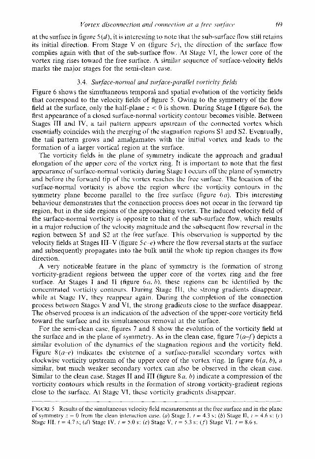
at the surface in figure 5 ( d ) , it is interesting to note that the sub-surface flow still retains its initial direction. From Stage V on (figure 5e) , the direction of the surface flow complies again with that of the sub-surface flow. At Stage VI, the lower core of the vortex ring rises toward the free surface. A similar sequence of surface-velocity fields marks the major stages for the semi-clean case.
3.4. Surface-normal and surface-parallel uorticity jields Figure 6 shows the simultaneous temporal and spatial evolution of the vorticity fields that correspond to the velocity fields of figure 5. Owing to the symmetry of the flow field at the surface, only the half-plane I’ < 0 is shown. During Stage I (figure 6a) , the first appearance of a closed surface-normal vorticity contour becomes visible. Between Stages 111 and IV, a tail pattern appears upstream of the connected vortex which essentially coincides with the merging of the stagnation regions SI and S2. Eventually, the tail pattern grows and amalgamates with the initial vortex and leads to the formation of a larger vortical region at the surface.
The vorticity fields in the plane of symmetry indicate the approach and gradual elongation of the upper core of the vortex ring. It is important to note that the first appearance of surface-normal vorticity during Stage 1 occurs off the plane of symmetry and before the forward tip of the vortex reaches the free surface. The location of the surface-normal vorticity is above the region where the vorticity contours in the symmetry plane become parallel to the free surface (figure 6a) . This interesting behaviour demonstrates that the connection process does not occur in the forward tip region, but in the side regions of the approaching vortex. The induced velocity field of the surface-normal vorticity is opposite to that of the sub-surface flow, which results in a major reduction of the velocity magnitude and the subsequent flow reversal in the region between S1 and S2 at the free surface. This observation is supported by the velocity fields at Stages 111-V (figure 5c-e) where the flow reversal starts at the surface and subsequently propagates into the bulk until the whole tip region changes its flow direction.
A very noticeable feature in the plane of symmetry is the formation of strong vorticity-gradient regions between the upper core of the vortex ring and the free surface. At Stages I and I1 (figure 6 a , b), these regions can be identified by the concentrated vorticity contours. During Stage I1 I , the strong gradients disappear, while at Stage IV, they reappear again. During the completion of the connection process between Stages V and VI, the strong gradients close to the surface disappear. The observed process is an indication of the advection of the upper-core vorticity field toward the surface and its simultaneous removal at the surface.
For the semi-clean case, figures 7 and 8 show the evolution of the vorticity field at the surface and in the plane of symmetry. As in the clean case, figure 7(a:f) depicts a similar evolution of the dynamics of the stagnation regions and the vorticity field. Figure 8 (a-e) indicates the existence of a surface-parallel secondary vortex with clockwise vorticity upstream of the upper core of the vortex ring. In figure 6 ( a , b), a similar, but much weaker secondary vortex can also be observed in the clean case. Similar to the clean case, Stages I1 and III (figure 8 a , b ) indicate a compression of the vorticity contours which results in the formation of strong vorticity-gradient regions close to the surface. At Stage VI, these vorticity gradients disappear.
FIGURE 5. Results of the simultaneous velocity field measurements a t the free surface and in the plane of symmetry z = 0 from the clean interaction case. (u) Stage I , t = 4.3 s; ( b ) Stage 11, I = 4.6 s ; (c) Stage 111. t = 4.7 s; ( d ) Stage IV, t = 5.0 s ; ( e ) Stage V, f = 5.3 s; ( , f ) Stage VI, t = 8.6 s.

70 M . Ghavib and A . Weigand
-z (cm) 3 (4 1 ,Y\,
, \
\
8 8 x(cm) 9 .. I x(cm) 9
10 10 J 11 11
x(cm) 9 I
10 4 11
FIGURE 6. For caption see facing page

Vortex disconnection and connection ( i f N f rec ~ u r f w t ~ 71
4. Vorticity and vorticity flux at the free surface The results in 93 showed that, as the vortex ring approaches the free surface, its
vorticity field in the symmetry plane weakens, while the surface-normal vorticity gains strength at the surface. The disappearance of surface-parallel vorticity from the symmetry plane indicates the disconnection process, while the appearance of surface- normal vorticity is an indication of the connection of the vortex ring to the free surface.
In this section, some analytical concepts are developed in order to describe and correlate the observed events at the free surface and in the plane of symmetry. The role of the strong vorticity-gradient regions, the dynamics of their removal, and the reasons for the existence of a secondary vortex in the clean and semi-clean case are discussed in detail. In conjunction with the experimental data, the analytical concepts are used to describe the evolution of the total circulation, and the condition and flux of vorticity at the surface.
4.1 . Free-surfuce Lwrticitx condition The issue of vorticity generation and vorticity flux at a free surface has only recently received recognition through the works of Lugt (1987, 1988), Lundgren (1988), Gharib et al. (1994) and Rood (1994a, h, 1995). Based on those investigations, the surface flux and boundary conditions are derived in the Appendix tjA.2. In general, the motion of the free surface is governed by the unsteady Navier-Stokes equation (Rood 1995):
?U v -+-+gl. - - - + u u x - v v x o . (; :: "j - c't
where u = ( u , ~ , w ) and w = ( m ) , ( o y , w z ) are the velocity and vorticity vectors in a Cartesian coordinate system, p is the pressure, p is the density and g is the gravitational acceleration.
The initial surface motion is induced by the irrotational velocity field of the approaching vortex ring. Therefore, it is reasonable to assume that the vorticity is zero and stays negligible during that initial phase (i.e. up to Stage I in our experiments). Therefore, the vector products on the right-hand side are negligible, and equation (1) can be integrated along the constant-pressure surface to obtain an expression for the surface elevation :
According to equation (2) and the schematic in figure 9, in the area downstream of the vortex (stagnation region SI), the fluid starts to accelerate in the negative x- direction and, therefore, rises due to the positive contribution of the acceleration integral. In this region, the free surface is characterized by negative surface velocities and a positive radius of the curvature. Upstream of the vortex, the velocity increases and the acceleration decreases. Therefore, the second term in equation (2) dominates and causes a trough at the surface which is characterized by a negative radius of curvature. As figure 9 shows, the change of the surface curvature between the stagnation regions indicates the existence of an inflection point (marked by I).
According to the Appendix 9A.2 and the schematic in figure 15(h), the surface-
FIGURE 6. Simultaneous vorticity field of the clean interaction case obtained from the velocity fields presented in figure 5. vorticity contours: (o,,,, = ~ ~ ~ 0 . 5 s I , A ~ O ~ , = A(,)? = 0.5 s l . ( ~ ~ f ) Stages I-VI, times as in figure 5.

72 M . Gharib and A . Weigand
-4 0 2 4 6 8
4
2
n
w o N I
-2
-4
~~
111. t=4.7 s
2 4 6 8 0 2 4 6 8
VI. t = 8 . 3 s
2
0
-2
FIGURE 7. Surface-normal vorticity fields of the semi-clean interaction case, vorticity contours : 6)y,0 = 0.5 S-', A w ~ = 0.5 S-'.

Vortex disconnection and connection at a free surface 73
s2 s1 s2 S1
v t = 3 . 9 s ~2 ' " ' ' ~ ~ ' ' " " ' ~ ' . " " . ' " "" " " _ " ' "
0 1 2 3 4 5 s2 s1 n ,
111. t =4.7 s -2 - , . . . . . .
0 1 2 3 4 5
0
-1
0
-1
i I\! t=5 .3s I -2"- - . " ' " " ' I " ' 1
2 3 4 5 6 7
V t = 8 . 3 s -2 "" """ " " ' ' . -
2 3 4 5 6 7
x ( 4 FIGURE 8. Surface-parallel vorticity fields of the semi-clean interaction case, vorticity contours :
wz,o = 0.5 s-', Aw2 = 0.5 SS'.
Direction fW flux
Direction +(d flux
Surface
Vortex ring
n Secondary vortex a FIGURE 9. Schematic of the various vorticity conditions at the free surface due to the approaching vortex ring, the subsequent surface deformation, and the formation of a secondary vortex. Regions with high density of surface contaminations (i.e. relatively small surface tension) are indicated by thick lines.

74 M . Ghurih and A . Weigund
parallel vorticity component w, at the free surface can be obtained in a local two- dimensional curvilinear coordinate system :
where 7,ir is the shear stress imposed by the air on the surface, g is the surface tension, R, is the local radius of curvature, and us and u, are the surface-parallel and surface- normal velocity components, respectively. Equation (3) defines the boundary condition and possible sources of surface-parallel vorticity at the surface. However, the existence of these sources does not necessarily imply that surface-parallel vorticity would flux into the body of motion.
In the absence of any strong air motion, the shear stress imposed by air on water can be neglected (i.e. 7,ir = 0). The combined effects of the third and fourth terms are manifested as unsteady changes of the surface slope (see the discussion in the Appendix, 5A.2 and equation (A 9)). It is therefore important to note that the free-surface vorticity condition can change during the approach to the vortex ring according to the evolution of the surface-deformation field.
The irrotational velocity field of the approaching vortex ring can redistribute the surface contaminants by transporting clean fluid from the bulk towards the surface. The latter results in the generation of surface-tension gradients. In the schematic of figure 9, regions with a high density of surface contaminants are indicated by a thick line.
By inspecting the schematic in conjunction with equation (3), one can identify regions that can possess a positive or negative vorticity condition near the surface. In the region between S1 and I, where S l is assumed to be close to the maximum height of the surface, the radius of curvature is positive, and the surface velocity is negative. Therefore, the term -u,/R is positive, which indicates the condition of positive vorticity in this region. In the same region, the surface-tension gradient acr/as is negative and, therefore, the term - l/,u(a~/c?s) is positive which also results in the condition of positive vorticity at the surface. Upstream of the inflection point, the radius of curvature is negative and the terms -u,/R and - l/,u@cr/as) are negative which supports the existence of negative vorticity near the surface. The role of the term &,/as can be clarified by inspecting the surface deformation induced by the approaching tip of the vortex ring in figure 9. Under these conditions, one can conjecture that, between S1 and I, the term au,/as is positive and, between I and S2, it is negative. Consequently, the contribution of this term supports the previously described surface condition of positive vorticity in the region between S1 and I and negative vorticity in the region between I and S2.
4.2. Flux of vorticity at the free surface According to Lugt (1988) and Rood (1995), the viscous flux of surface-parallel vorticity through the surface can be derived in a two-dimensional curvilinear coordinate system (see the Appendix 5A.3) and results in
where w, and u, are the surface-parallel vorticity and velocity components, p is the pressure at the surface, and 0 is the angle between the surface and the gravitational acceleration. Obviously, any analysis based on equation (4) can only be made in a local sense, since the surface is free to make vertical excursions and change its shape.

Vortex disconnection and connt’ction at N free 5iirfuce 75
FIGURE 10. Vorticity-flux terms and net vorticity flux on the centreline Y at various stages during the clean interaction.
A positive value of v(C?~,/(?r) indicates an inward flux (in the negative r-direction) of positive vorticity, while a negative value indicates an outward flux (in the positive r- direction) of positive vorticity. Assuming a constant-pressure surface (c‘p/(?s = 0) and small surface slopes (gcos 0 z 0), the integration of equation (4) along s from - 00 to + 00 yields that the net surface-parallel vorticity contribution only arises from the temporal acceleration of the surface flow, i.e.
where us = 0 as s + -t oc for all times. However, in order to understand the local dynamics of vorticity near the surface, the
temporal and advective acceleration terms must be taken into account. Figure 10 shows the resulting temporal and advective acceleration terms -c‘u,/c?t and - u,c?u,/?s

76 M . Gharib and A . Weigand
on the centreline for various stages of the free-surface interaction. At Stage I (figure 10a), the region of positive vorticity in the schematic of figure 9 is dominated by a net inward flux of positive vorticity. This flux term reaches a maximum in the mid-region between Sl and I and decreases to zero at the inflection point I. The initial inward flux of positive vorticity in the region between S1 and I should result in the early appearance of positive vorticity very close to the free surface. The limited resolving power of the DPIV system and the difficulties involved with the near-surface illumination did not allow us to detect this vorticity region. However, since the positive vorticity region interacts with the same-sign vorticity of the upper core of the vortex ring, the vorticity contours should spread toward the free surface. This spreading can be seen clearly in figure 6(b).
As figure 10(a) shows, a net inward flux of negative vorticity dominates the region upstream of the inflection point, where the condition of negative vorticity already exists due to the surface deformation and the surface-tension gradient (see $4.1). According to the schematics in figure 9, this flux causes an accumulation of negative vorticity in the sub-surface region which leads to the self-induced roll-up of the observed secondary vortex (Kaden 1931). These features are expected to be more prominent in flows with higher Froude numbers (i.e. larger surface deformations) such as numerically simulated by Ohring & Lugt (1995), for example.
Between Stages I1 and IV (figure lob, c), when the surface velocities between S1 and S2 start to decrease and eventually reverse, the distribution of the net flux shifts to a negative value as the upper core of the vortex ring collides with the surface. Note that the net outward flux of positive vorticity is mainly due to the -au,/at term and not the -uU,au,/as term. During Stages I11 and IV, this flux is responsible for the removal of positive and surface-parallel vorticity from the sub-surface region between S1 and I. Therefore, it facilitates the subsequent removal of vorticity from the plane of symmetry that lies between the regions where the surface-normal vorticity was first observed to appear. Similarly, the inward flux of negative vorticity in the region between I and S2 adds more to the existing negative vorticity and, therefore, accentuates the formation of the secondary vortex.
4.3. The secondary vortex The existence of the secondary vortex can be seen clearly in the surface-parallel vorticity fields of the clean case (figure 6) and, with a much stronger appearance, in the semi- clean case in figure 8. As was discussed in $4.2, in the case of a clean and non- contaminated surface, and in the absence of any surface deformation, the secondary vortex cannot be formed. Owing to the curvature of the upper part of the vortex ring, the induced surface-velocity field will have a finite-size span during the early interaction. The finite-size region is clearly visible in the shadowgraph images of figure 3 and suggests that the secondary vortex has a finite length with decreasing vorticity strength towards its ends. The diminishing vorticity magnitude in the end regions of the secondary vortex allows for a non-surface-normal termination of this vortex. Therefore, on the free surface, we should not expect the appearance of surface-normal vorticity due to the secondary vortex.
4.4. Temporal evolution of the circulation at the surface In the present studies, the temporal evolution of the circulation in the bulk and at the free surface is used to demonstrate the connection process. Figure 11 shows the circulation that is lost by the upper core of the vortex ring and gained due to the connected vorticity at the free surface. In the clean and semi-clean flow cases, the loss of circulation in the plane of symmetry occurs at a similar rate. The initially slow decay

Vortex disconnection and connection at a .free surface 77
I " " " " " " " " " " " " " " ' 1
r TO - 0 6 -
0 4 - ~ Semi-clean case .
Secondary vortex in symmetry plane
Stages of semi-clean case I
Stages of clean case I I
FIGURE 1 1. Temporal evolution of the circulation at the free surface and in the plane of symmetry 3 = 0 for the clean and semi-clean case.
of the circulation is followed by a rapid loss and a subsequent asymptotic decay towards zero. In their numerical studies, Leighton & Swean (1991) report a similar gain and loss of vorticity at the free surface and in the plane of symmetry.
In comparison to the semi-clean case, the gain of free-surface circulation in the clean case is characterized by a relatively steep slope and a slightly delayed appearance. The steeper slope suggests that the connection process in the clean case has a shorter time scale than in the semi-clean case. In both flow cases, the final level of circulation at the surface is the same and accounts for approximately 85 % of the initial circulation of the vortex ring. Figure I1 also shows that the evolution of the secondary vortex is characterized by a circulation maximum at the beginning and a rapid decay by the end of the connection process.
4.5. Vortex connection timescale One of the intriguing features that Bernal & Kwon (1989) reported was the rapid nature of the connection process. In $4.2, it was shown that the main mechanism for the disconnection of the vortex ring near the surface is the rapid viscous flux of vorticity. From the evolution of the circulation in figure 11, the timescales for the disconnection and connection process can be observed to be similar, i.e. the time for the flux of surface-parallel vorticity out of the plane of symmetry approximately corresponds to the time that the circulation takes to reach a maximum value at the surface. For example, based on the slope of the loss and gain of circulation, the results in figure 11 suggest a disconnection timescale of 2.5 s and a connection timescale of 2.2 s in the clean case. In the semi-clean case, the disconnection and connection timescales are similar at approximately 2 s and 2.5 s, respectively.
In combination with the vorticity-flux equation (equation (4)), which is mainly applicable during the disconnection process and the outward flux of surface-parallel vorticity, the resulting disconnection timescale can be used to obtain an estimate for the timescale of the connection process. In $ 5 , we will conjecture on the underlying reasons for this close relation between the two timescales.
With the assumption that only temporal surface accelerations are responsible for the

78 M . Gharib und A . Weigand
0
-0.5
-I .O
-1.5
-2.0 - 2 0 2 4 6 8 10
FIGURE 12. Surface-parallel vorticity and velocity profiles at t = 5.0 s: (a) semi-clean case, (b) clean case.
connection process (see figure lob, c and the discussion at the end of $4.2), an expression for the disconnection and connection timescales can be obtained from equation (4) in the form of
where Au is the velocity difference and AwJAr is a best fit value for the vorticity distribution between the free surface and the location of the vorticity maximum in the plane of symmetry.
In a first-order estimate, the vorticity gradient near the surface is approximated by an average value which introduces a lengthscale based on the local vorticity thickness. Figure 12 shows the near-surface velocity and vorticity profiles at t = 5.0 s which corresponds to the point in time where the vortex ring is half-way through the disconnection and connection process (see figure 11). In the clean case, the maximum value of AwJAr is 17.5 cm s-l, and the corresponding velocity difference Au is 0.4 cm s-I. Equation (6) gives a connection timescale of At z 2.3 s which is surprisingly close to the experimentally observed value of 2.2 s obtained from the evolution of the circulation in figure 11. In the semi-clean case, a similar estimate gives a connection timescale of At w 4.1 s which is larger than the observed value of 2.5 s, but close enough to be considered as a good first-order estimate.
The relevant parameters in estimating the disconnection and connection time (1.e. Awz, Au, and Ar) strongly depend on the angle of approach, vorticity structure in the core region, and the Reynolds number of the flow. This is a vast parameter space that was not covered in our studies. However, the dependency on the angle of approach (Bernal & Kwon 1989) and the distribution of vorticity in the core region makes the possibility of finding a global scaling law slim.
5. Kinematics and dynamics of the approaching vortex ring In $3.1, we mentioned that the generated vortex rings have a core to vortex-ring
diameter ratio of approximately 0.6. This implies that the vortex rings in our experiments have a relatively thick core, and, therefore, their kinematics and dynamics cannot be modelled as single vortex filaments. As the vortex ring approaches the free surface, but is not yet close enough to be influenced by the surface deformation, the vorticity field in the plane of symmetry (figure 6 a ) suggests that the upper part of the vortex ring is staggered backward in the negative x-direction. A similar behaviour has

Vortex disconnection and connection at a free surface 79
( a ) Y\ Secondary vortex (b) y 4 First connection site , I in side regions
1 ? A Z' ,a,
a, < \ ' I
StdgC vI I '
, \ - / j
FIGURE 13 Sequence of events of the disconnection and connection process during the
<\
I i t a g e 1 "x
/' \ , .-
vortex-ring/free-surface interaction
been reported for flow cases where two vortex rings approach each other at an oblique angle (Schatzle 1987). In our case, the initially non-deformed surface acts as a shear- free symmetry plane. According to Ashurst & Meiron (1987), this stretching action is due to the interaction of the vortex ring with its image vortex above the free surface (see figure 1 of Ashurst & Meiron). Zhang & Yue (1996), who recently simulated the interaction of a vortex ring with a free surface, report a similar behaviour.
The strain field that is induced on this backward-staggered region by the velocity field of the vortex ring plays an important role in determining the mechanisms that are responsible for the connection process. Figure 13 shows a sequence of schematics of the approaching vortex ring and its interaction with the free surface. To justify the illustrated dynamics, we start by considering the regions where the top portion of the vortex ring bends downward away from the plane of symmetry and the surface. In figure 13 (b), those regions are identified as side regions. They possess surface-normal vorticity components in the bulk and, therefore, are the most plausible candidates to connect to the free surface first. This conjecture is supported by the numerical observations of Kida, Takaoka & Hussain (1989), who report the side regions as the primary connection sites of vortex rings that approach each other at an oblique angle.
To examine this conjecture, we apply the vorticity-transport equation and evaluate the various terms for the deformed vortex ring close to the free surface. In this analysis, viscous effects and effects of surface deformations are neglected; a local Cartesian coordinate system with the velocity vector u = (u, u, w) and the vorticity vector o = (w5, wv, wz) is used. From the maternal change
Dw Dt - _ - (o .V)u , (7)

80 M . Gharib and A . Weigand
Side region (z < 0)
Side region (z > 0 )
X
FIGURE 14. Schematic of the strain rate and vorticity field during the initial approach of the vortex ring.
the rate of change of the surface-normal vorticity vector (y-component) due to tilting is
(8)
According to figure 14, near the tip region of the vortex ring, the z-component of the vorticity vector is dominant (i.e. w, = O), while the y-component of the induced velocity field is symmetric about the plane of symmetry z = 0 (i.e. av/az = 0). Therefore, equation (8) yields -
u w 2 = 0, Dt (9)
and states that the tilting and subsequent connection of vortex filaments to the free surface cannot be expected to occur near the central tip region of the vortex ring.
In the side region z < 0, w, and &/ax are both negative. Therefore, the tilting term w, av/ax is positive and contributes to the production of positive surface-normal vorticity (wy > 0). Regarding the tilting term w, av/az in the region z < 0, w, and av/az are both positive and also contribute to the production of a positive w,-component. Similarly, in the side region z > 0 and for both tilting terms, the vorticity and strain- field analysis results in the production of negative surface-normal vorticity (wy < 0). These results are consistent with the observations in $4 and figure 6, where the first appearance of surface-normal vorticity was observed to occur in the side regions.
It is important to note that the free-surface condition of zero shear stress requires that the vortex filaments connect normal to the free surface (see the Appendix, §A. 1). The Helmholtz theorem requires that a vortex filament does not terminate in the bulk of the fluid, but rather extends to the boundaries. Therefore, any disconnected vortex
Vortex disconnection and connection ut a .free surfuce 81
filament near the free surface is required to connect normal to the surface. Such an argument would apply in the region that bridges the surface-connected side regions. Owing to the removal of positive vorticity from the symmetry plane in this bridging region, disconnected vortex filaments connect to the free surface and add to the strength of the already connected vortices (Stages I1 to V in figures 6 and 13). This process explains the link between the loss of surface-parallel vorticity from the plane of symmetry and the gain of circulation at the surface.
The appearance of the tail pattern in the surface-vorticity field during Stage TI1 (figure 6c) and its evolution can be attributed to the rapid forward motion of the stagnation region S2. This motion, which is due to the induced velocity field of the surface-normal vorticity in the side regions, can generate strong local surface-velocity gradients (u- and w-components). The rate of change of these gradients can be considered to be a source of surface-normal vorticity (Rood 1995). We observed the existence of those gradients in our experiments. However, owing to the required triple derivations and the inherent increase in the noise level, it is difficult to obtain reliable estimates of the surface-normal vorticity flux terms from the surface-velocity data.
6. Concluding remarks The physical model described suggests that the connection of an approaching vortex
ring to a free surface occurs in two steps. The first step involves the connection of the regions of the vortex ring that already possess components of surface-normal vorticity near the surface. We showed that the action of the local strain-rate field supports this early connection process.
DPIV measurements show that the second step, which involves the disconnection of the connected regions of the vortex ring, is associated with a strong outward flux of vorticity from the central top region of the approaching vortex ring. Such removal of vorticity due to local surface decelerations facilities the connection of surface-normal vorticity to the surface, which is required by the kinematic condition imposed by the shear-free surface condition. The connection and disconnection timescales were estimated based on the local vorticity flux and the local viscous flow properties near the surface. The estimates agree very well with the measured values. It was shown that the approaching vortex is capable of generating a secondary vortex and that a less clean surface is capable of generating a stronger secondary vortex. While we commented on the subject of surface-normal vorticity flux through the surface, high-spatial- and temporal-resolution DPIV measurements must be conducted in order to properly address this issue.
This work has been supported by the Office of Naval Research, ONR-URI grant N00014-92-5-1610. The authors would like to thank Dr Willert for his contributions during the initial processing of the DPIV data. The valuable discussions with Dr Rood and Dr Ashurst on the subject of vortex kinematics and vorticity flux have been essential to our presentations in the paper.
Appendix
A free surface can be distinguished from a no-slip, solid boundary by its inability to support shear and its ability to make free vertical excursions. A flat surface condition can be used to demonstrate the special condition that a vortex filament has to follow
A. 1. Vorticity elements and free surface

82 M . Gharib and A . Weigand
Free surface
z, w, q
FIGURE 15. (a) Local Cartesian coordinate system. (b) Local curvilinear coordinate system.
in order to connect to a free surface. The flat surface condition is proper when the radius of curvature approaches infinity. However, one can always think of local interactions where precise flat surface conditions with non-zero slope can be used. In a local Cartesian coordinate system with the velocity vector u = (u, v, w) (see figure 15a), the vorticity vector is given by
0 = (wzr wy, 4, with the components
a w av au a w av au OJ =--- w = - - - w = - - - ay aZ3 y aZ ax’ * ax ay.
Using the flat surface condition (v = const.) and the zero-shear-stress condition at the surface ( T ~ ~ = T~~ = 0), the following terms can be eliminated: av/az = av/ax = au/ay = aw/i3y = 0. This leaves only the w,-component of the vorticity vector re- maining at the flat free surface and forces vortex lines to terminate normal to the surface. In contrast, the no-slip wall only permits the existence of wall-parallel vorticity.
The surface-normal termination of vortex lines applies only at the surface. Immediately below the surface, surface-parallel vorticity can exist without violating any surface condition. However, as a consequence of the kinematic condition, vortex filaments cannot terminate within the fluid, and disconnected filaments will have a tendency to connect normal to the nearby surface.
A.2. Vorticity boundary conditions at a free surface As has already been shown by Lugt (1987, 1988), flow beneath a shear-free and curved surface produces surface-parallel vorticity at the interface. Both analyses treat only the steady case where the net-vorticity production below the surface remains zero. Following Lundgren (1988) and Gharib et al. (1994), we present the derivation of a

Vortex disconnection tri i t l cotiiicv~lioii lit 11 $YYJ surfuce 83
more general expression for the boundary condition of surface-parallel vorticity in the unsteady flow case. Using a curvilinear coordinate system (see figure 15b), the analysis is performed for the two-dimensional flow case (i.e. the radius of curvature R, in the r , z-plane is infinite).
The shear stress rrS on the surface has two components: (i) the stress T , ~ ~ imposed by the air on the liquid and (ii) the stress ?n/c's created by surface tension gradients:
This interfacial shear stress is balanced by the stress on the fluid element below the surface :
where u, and u,. are the surface-parallel and surface-normal velocity components and R, is the local radius of curvature (Schlichting 1987). The corresponding vorticity component parallel to the boundary (i.e. the free surface here) is given by
At the interface r = 0, the stresses balance and using equation (A 5 ) to replace the term c?u,/c?r yields the expression for the surface-parallel vorticity
Equation (A 6) is the boundary condition for the contaminated and deformed surface and contains four sources of vorticity: (i) the shear force imposed by the adjoining medium which, in the case of air, is negligible; (ii) the force due to surface tension gradients; (iii) the curvature of the surface itself as already set forth by Lugt (1987); (iv) the vertical motion of the surface which has the characteristics of an unsteady term.
It is interesting to note that, if the shape of the free surface is described by the function y = y/(x, I ) in two-dimensional Cartesian coordinates, the surface-normal velocity component and the surface-parallel vorticity component can be expressed as
c?q i t '
z ' = -
and
The term c?q/?s defines the one-dimensional slope S of the free surface (i.e. S = &~/2x), and therefore, equation (A 8) becomes
A comparison of equations (A 6) and (A 9) shows that the combined effect of the last two terms in equation (A 6) can be thought of as being equivalent to an unsteady change of the li.ce-surfi.tce slope.

84 M . Gharib and A . Weigand
A.3. Vorticitypux at a free surface Rood (19944 has presented a rigorous approach to extend Lugt's (1987) formulation to the case of unsteady vorticity flux at a free surface. Here, we present a similar though less rigorous derivation by using the continuity and momentum equation in a two- dimensional curvilinear coordinate system (figure 15 b) :
R, au, au, u +-+A = 0, ___
R,+r as ar R,+r
au, R, au au u,u, -+- us>+ u++- at R,+r as ar R,+r
+ 2R, -+ au, R,r -__- au,aR, Rsur !!.!$) (A 1 1 ) (R,+r)' as (R,+r)3 as as (R,+r)3 as '
where g is the gravitational acceleration and 0 is the local angle of the free surface to the gravitational vector.
The viscous flux of surface-parallel vorticity (0,-component) is obtained by differentiating equation (A 5 ) with respect to r :
In equation (A 12), the term R,/(R,+r)a2u,/i3sar can be substituted by the corresponding term of equation (A 10) which is first differentiated with respect to s. The substitution yields
R; a2u, azu, 1 au, %-- - _ _ _ ~ _ _ _ _ _ ar (R,+r)' i3s2 ar' R,+r ar
aRs (A 13)
The comparison of equation (A 13) with the momentum diffusion on the right hand
US 2 ~ , au, R, au +-- (R, + r)' (R, + r)' X - ( R , + r)3 I' $-',I as' side of equation (A 1 1 ) yields the viscous flux of surface-parallel vorticity :
With the expression for vorticity (equation (A 5))
au u Rs aur 0) = - - s - s +-- ar R,+r R,+r as'
equation (A 14) becomes
At the surface, where r = 0 and u, = 0, the surface-parallel vorticity flux results from equation (A 15) :
(A 16a)

Vortex disconnection and connection at a free surface 85
with the total head of the surface defined by
H = ;u; +-+gscos P 0. (A 16b) P
Equations (A 16) predict that any removal or introduction of surface-parallel vorticity through the interface is balanced by a change in the hydrodynamic head H and/or a local surface acceleration/deceleration.
R E F E R E N C E S ASHURST, W. T. & MEIRON, D. 1. 1987 Numerical study of vortex reconnection. Phys. Rev. Lett. 58,
BERNAL, L. P., HIRSA, A,, KWON, J. T. & WILLMARTH, W. W. 1989 On the interaction of vortex rings and pairs with a free surface for varying amounts of surface active agent. Phys. Fluids A 1,
BERNAL, L. P. & KWON, J. T. 1989 Vortex ring dynamics at a free surface. Phys. Fluids A 1,449-451. CHU, C. C., WANG, C. T. & HSIEH, C. S. 1993 An experimental investigation of vortex motions near
surfaces. Phys. Fluids A 5 , 662-676. DOMMERMUTH, D. G. 1992 The formation of U-shaped vortices on vortex tubes impinging on a wall
with applications to free surfaces. Phys. Fluids A 4, 757-769. GHARIB, M. 1994 Some aspects of near-surface vortices. In Proc. Twelfth US National Congress of
Applied Mechanics, June 1994, Seattle, W A (ed. A. S. Kobayashi), Appl. Mech. Rev. 47,
GHARIB, M., WEIGAND, A., WILLERT, C. & LIEPMANN, D. 1994 Experimental studies of vortex reconnection to a free surface: A physical flow model. In Proc. Nineteenth Symposium on Naval Hydrodynamics, August 1992, Seoul, Korea, pp. 507-520. National Academy Press.
1632-1635.
2001-2004.
S157-S 162.
KADEN, H. 193 1 Aufwicklung einer unstabilen Unstetigkeitsflache. Ing. Arch. 140, 140-168. KIDA, S., TAKAOKA, M. & HUSSAIN, F. 1989 Reconnection of two vortex rings. Phys. Fluids A 1,
KWON, J . T. 1989 Experimental study of vortex ring interaction with a free surface. PhD thesis, University of Michigan.
LEIGHTON, R. I. & SWEAN, T. F. 1991 The enstrophy balance during the interaction of a vortex ring with a shear-free boundary. In Dynamics of Bubbles and Vortices Near a Free Surface. AMD, vol.
LIM, T. T. 1989 An experimental study of a vortex ring interacting with an inclined wall. Exps. Fluids
LUGT, H. J. 1987 Local flow properties at a viscous free surface. Phys. Fluids 30, 3647-3652. LUGT, H. J. 1988 Fundamental viscous flow properties at a free surface. Fluid Dyn. Trans. 14, 57-76. LUNDGREN, T. S. 1988 A free surface vortex method with weak viscous effects. In Mathematical
Aspects of Vortex Dynamics (ed. R. E. Caflish), pp. 68-79. SIAM. OHRING, S. & LUGT, H. J. 1991 Interaction of a viscous vortex pair with a free surface. J . Fluid
Mech. 227, 47-70. OHRING, S. & LUGT, H. J. 1995 Interaction of an obliquely rising vortex ring with a free surface in
a viscous fluid. Accepted for publication in Meccanica. ROOD, E. P. 1994u Interpreting vortex interactions with a free surface. Trans. ASME I: J . Fluids
Engng 116, 91-94. ROOD, E. P. 19946 Myths, math, and physics of free-surface vorticity. In Proc. Twelfth US National
Congress oj'Applied Mechanics, June 1994, Seattle, W A (ed. A. S . Kobayashi). Appl. Mech. Rev.
ROOD, E. P. 1995 Free-surface vorticity. In Fluid Vortices (ed. S. I. Green), pp. 687-730. Kluwer. SARPKAYA, T. & HENDERSON, D. 0. 1985 Free surface scars and striations due to trailing vortices
SCHATZLE, P. R. 1987 An experimental study of fusion of vortex rings. PhD thesis, California
630-632.
119, pp. 75-88. ASME.
7, 453463.
47, S152-SI56.
generated by a submerged lifting surface. AIAA Paper 85-0445.
Institute of Technology.

86
SCHLICHTING, H. 1979 Boundary-Layer Theory, 7th edn (reissued 1987), pp. 67-69. McGraw-Hill. SCOTT, J. C. 1982 Flow beneath a stagnant film on water: the Reynolds ridge. J . FLuidMech. 116,
WEIGAND, A. 1995 Simultaneous mapping of the velocity and deformation field at a free surface.
WEIGAND, A. & GHARIB, M. 1995 On the evolution of laminar vortex rings. Submitted to Exps.
WILLERT, C. E. & GHARIB, M. 1991 Digital particle image velocimetry. Exps. Fluids 10, 181-193. WILLERT, C. E. & GHARIB, M. 1995 The interaction of spatially modulated vortex pairs with a free
ZHANG, C. & Ym, D. P. 1996 On vortex connection at a free surface. In preparation for submission
M . Gharib and A . Weigand
283-296.
EXPS. Fluids 20, 358-364,
Fluids.
surface. Submitted to J . Fluid Mech.
to J . Fluid Mech. and private communication.