experimental response of rc beams strengthened in … · keywords: beam slenderness, cracking,...
TRANSCRIPT

Send Orders of Reprints at [email protected]
The Open Civil Engineering Journal, 2013, 7, 127-135 127
1874-1495/13 2013 Bentham Open
Open Access
Experimental Response of RC Beams Strengthened in Shear by FRP Sheets
E. Grande, M. Imbimbo* and A. Rasulo
Department of Civil and Mechanical Engineering, University of Cassino and Southern Lazio, Italy
Abstract: The paper discusses the results of an experimental investigation carried out on reinforced concrete (RC) beams
strengthened in shear by externally bonded fiber reinforced plastic (FRP) sheets. The study is devoted to analyze the role
that the transverse steel reinforcement and the beam slenderness ratio could play on the resistant mechanism of RC beams
strengthened in shear by FRP composites. The results are summarized and analyzed in detail in the paper in terms of shear
capacity, cracking pattern and shear resisting contribution of FRP.
Keywords: Beam slenderness, cracking, FRP-shear strengthening, RC beams, steel stirrups.
1. INTRODUCTION
The use of composite materials, mainly fiber reinforced polymers (FRP) and, more recently, cement based composite and steel reinforced polymers (SRP), and steel reinforced grout (SRG), in the strengthening of existing RC and mason-ry structures [1-7] has become a common technique widely adopted in the past decade. Particularly for the case of RC structures, several studies (i.e. [8-12], etc.), together with code recommendations [13-15], testify the grade of aware-ness the research community has reached in the development of theoretical models and design rules to be adopted in the application of this strengthening technique.
Nevertheless, there are some aspects, which would re-quire further investigations. Among these, the influence of the transverse steel reinforcement and of the slenderness ra-tio on the resistance mechanism of RC beams strengthened in shear by FRP is certainly an important issue. Indeed, the results emerged from recent experimental studies [16-29] have clearly pointed out that an interaction exists between the resisting mechanisms provided by steel stirrups and FRP. However, the theoretical formulations proposed by the actual codes for evaluating the shear contribution of FRP rein-forcement neglect this aspect with the consequence of over-estimating the contribution of FRP to shear resistance in some circumstances.
This paper aims at investigating experimentally the effect of the transverse steel and the slenderness ratio on the re-sponse of RC beams strengthened in shear by FRP. For this purpose, the results of an experimental investigation carried out by the authors on RC beams strengthened in shear by ex-ternally bonded FRP sheets are presented. The investigation consists of two phases: the first one is focused on the
*Address correspondence to this author at the Department of Civil and
Mechanical Engineering, University of Cassino and Southern Lazio, Italy;
Tel: +39.0776.299.3740; Fax: +39.0776.299.3392;
E-mail: [email protected]
influence of the steel stirrups and the second one concerns the role of the beam slenderness ratio. Some of the results of each phase have been already object of discussion in [26, 30]. Here, the aim of the paper is to globally present the re-sults of the experimental activity and develop a more com-prehensive discussion on the following points: (i) effect of the transverse steel amount and the FRP strengthening con-figuration and (ii) influence of the beam slenderness ratio on the shear contribution of the FRP, with the intent of analyz-ing and comparing the role of the considered parameters on the resistant mechanism of the examined beams.
It is evident that the number of the tests discussed in the paper is not sufficient to calibrate a theoretical model able to account for the influence of the steel stirrups and the slen-derness ratio on the shear contribution of FRP strengthening system. However, the results of the tests have certainly evi-denced the role that these parameters could have on the in-teraction mechanism between the RC beams and the strengthening system, an effect that is completely neglected in actual design formulas.
2. SPECIMENS, SETUP AND INSTRUMENTATION
Three series of full-scale RC beams strengthened in shear by carbon fiber reinforced sheets applied on the external beams surface through epoxy resin have been tested (Fig. 1). The beams have been characterized by different strengthen-ing configurations, percentage of steel stirrups, beam slen-derness, configuration and instrumentation set up. For all the tested beams, the same concrete mixing, steel reinforcement and reinforcing system (adhesive and FRP) have been used. In particular, a concrete mix consisting of Portland cement was adopted. Compression standard tests have been per-formed on 45 control standard cubic specimens (dimensions 150x150x150 mm3) cast and cured at the same time and un-der the same conditions of the tested beams according to the indications contained in the Italian document UNI 6132 [31]. The obtained average cylindrical compression strength, f’c,
128 The Open Civil Engineering Journal, 2013, Volume 7 Grande et al.
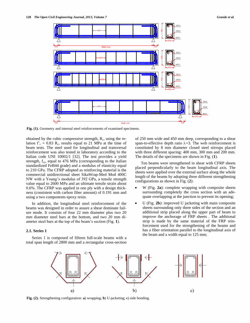
obtained by the cubic compressive strength, Rc, using the re-lation f’c = 0.83 Rc, results equal to 21 MPa at the time of beam tests. The steel used for longitudinal and transversal reinforcement was also tested in laboratory according to the Italian code UNI 10002/1 [32]. The test provides a yield strength, fsy, equal to 476 MPa (corresponding to the Italian standardized FeB44 grade) and a modulus of elasticity equal to 210 GPa. The CFRP adopted as reinforcing material is the commercial unidirectional sheet SikaWrap-Med Mod 400C NW with a Young’s modulus of 392 GPa, a tensile strength value equal to 2600 MPa and an ultimate tensile strain about 0.6%. The CFRP was applied in one ply with a design thick-ness (consistent with carbon fiber amount) of 0.191 mm and using a two components epoxy resin.
In addition, the longitudinal steel reinforcement of the beams was designed in order to assure a shear dominate fail-ure mode. It consists of four 22 mm diameter plus two 20 mm diameter steel bars at the bottom, and two 20 mm di-ameter steel bars at the top of the beam’s section (Fig. 1).
2.1. Series 1
Series 1 is composed of fifteen full-scale beams with a total span length of 2800 mm and a rectangular cross-section
of 250 mm wide and 450 mm deep, corresponding to a shear span-to-effective depth ratio =3. The web reinforcement is constituted by 8 mm diameter closed steel stirrups placed with three different spacing: 400 mm, 300 mm and 200 mm. The details of the specimens are shown in Fig. (1).
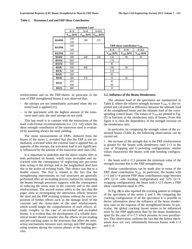
Ten beams were strengthened in shear with CFRP sheets placed perpendicularly to the beam longitudinal axis. The sheets were applied over the external surface along the whole length of the beams by adopting three different strengthening configurations as shown in Fig. (2):
W (Fig. 2a): complete wrapping with composite sheets surrounding completely the cross section with an ade-quate overlapping at the junction to prevent its opening;
U (Fig. 2b): improved U jacketing with main composite sheets surrounding only three sides of the section and an additional strip placed along the upper part of beam to improve the anchorage of FRP sheets . The additional strip is made by the same material of the FRP rein-forcement used for the strengthening of the beams and has a fiber orientation parallel to the longitudinal axis of the beam and a width equal to 125 mm;
4Ø22
250
450
150 1502800 mm
2Ø20
2Ø22
400
300
200
250
450
250
450
4Ø22
2Ø20
2Ø22
4Ø22
2Ø20
2Ø22
4Ø22
250
450
150 1503600 mm
2Ø20
2Ø22
400
Fig. (1). Geometry and internal steel reinforcements of examined specimens.
Fig. (2). Strengthening configuration: a) wrapping; b) U-jacketing; c) side bonding.

Experimental Response of RC Beams Strengthened in Shear by FRP Sheets The Open Civil Engineering Journal, 2013, Volume 7 129
S (Fig. 2c): side bonding with composite sheets placed only at the beam lateral surface.
The remaining five beams were not strengthened and used as control beams (see Table 1).
Each specimen is labeled by a five character designation: RSnWL3, RSnUL3, RSnSL3 and RSnNRL3, where R de-notes that the beam has a rectangular section; Sn indicates the stirrup spacing, assuming in our case, the values S4, S3 or S2, standing respectively for 400, 300 or 200 mm; W, U, S and NR indicate the strengthening configuration, previous-ly named as complete wrapping (W), improved U jacketing (U), side bonding (S) or not strengthened (NR); L3 indicates the aspect ratio equal to 3 for all the specimens of this series; finally, the eventual a or b suffix indicating the typology of the instrumentation set-up as detailed in the following. De-tails of specimens are illustrated in Table 1.
All the specimens of series 1 were tested as a simple sup-ported beam subjected to a three-point loading condition as illustrated in Fig. (3). A 1000kN hydraulic jack was used to apply the load at the midpoint. In all specimens, the midpoint deflection was monitored by a vertical displacement trans-ducer. For all specimens, three strain gauges (P1b, P2b, P3b)
were mounted on the longitudinal steel bar surface at differ-ent positions, and two strain gauges (S1b, S2b) were mount-ed on two different stirrups. Details of the instrumentation are reported in Fig. (3).
A part from the aforementioned instrumentation common to all the specimens, in only seven beams additional strain gauges were attached directly on the external surface of the FRP sheets (Table 1). The strain gauges were oriented in the vertical direction and located in different sections with the purpose to monitor the strain variation in the FRP. In particu-lar, two different kinds of set-up schemes were adopted, one for the wrapping and U jacketing configuration, and another for the side bonding configuration as shown in Fig. (4).
2.2. Series 2
Series 2 is composed of four full-scale beams with a total span length of 3600 mm and a rectangular cross-section of 250 mm wide and 450 mm deep, corresponding to a shear span-to-effective depth ratio =4. The web reinforcement is constituted by 8 mm diameter closed steel stirrups placed with a spacing equal to 400 mm. The details are shown in Fig. (1).
Table 1. Details of the Examined Specimens
SERIES Label Slenderness Stirrups
Spacing (mm)
Strengthening
Configuration Test Instrumentations
SE
RIE
S 1
RS4NRL3
3
400
none Strain gauges on the steel
Displacement transducer at the midpoint of span RS3NRL3 300
RS2NRL3 200
RS4WL3
3
400
Wrapping
Strain gauges on the steel
Displacement transducer at the midpoint of span
Strain gauges on FRP
RS3WL3 300
RS2WL3 200
RS3UL3 300 U+ jacketing
RS2UL3 200
RS3SL3 300 Side bonding
RS2SL3 200
RS4NRL3 3
400 none
Strain gauges on the steel
Displacement. transducer at the midpoint of span
RS3NRL3 300
RS4UL3 3 400 U+ jacketing
RS4SL3 3
400 Side bonding
RS3SL3 300
SE
RIE
S 2
RS4NRL4
4 400
none
Strain gauges on the steel
Displacement transducer at the midpoint of span
RS4WL4 Wrapping
RS4UL4 U+ jacketing
RS4SL4 Side bonding
SE
RIE
S
3 RS4NRL2.5
2.5 400 none Strain gauges on the steel
Displacement transducer at the midpoint of span RS4WL2.5 Wrapping

130 The Open Civil Engineering Journal, 2013, Volume 7 Grande et al.
Three beams were strengthened in shear with CFRP sheets placed perpendicularly to the beam longitudinal axis. The sheets were applied over the external surface along the whole length of the beams by adopting the three different strengthening configurations used for series 1 that is com-plete wrapping (W), improved U jacketing (U) and side bonding (S). The fourth beam was not strengthened and used as control beam (see Table 1). The four beams of this series are labeled RS4WL4, RS4UL4, RS4SL4 and RS4NRL4 (Table 1).
All the specimens of the series 2 were tested as a simple supported beam subjected to a three-point loading condition as illustrated in Fig. (3) as in the case of the beams of the se-ries 1. In all specimens the midpoint deflection was moni-tored by a vertical displacement transducer. For all speci-mens, three strain gauges (Ln1, Ln2, Ln3) were mounted on the longitudinal steel bar surface at different positions, and two strain gauges (St1, St2) were mounted on two different stirrups (Fig. 4).
2.3. Series 3
Series 3 is composed of two full-scale beams with a total span length of 2800 mm and a rectangular cross-section of
250 mm wide and 450 mm deep, corresponding to a shear span-to-effective depth ratio =2.5. The web reinforcement is constituted by 8 mm diameter closed steel stirrups placed with a spacing equal to 400 mm.
One of the beams was strengthened in shear with CFRP sheets placed perpendicularly to the beam longitudinal axis by using a complete wrapping configuration (W), whilst the other one was not strengthened and used as control beam.
The two beams of this series are labeled RS4WL2.5 and RS4NRL2.5 (see Table 1).
In this case, the beams were tested as a simple supported beam subjected to a four-point loading condition as illustrat-ed in Fig. (3). The four-point loading condition allows to ob-tain a shear span-to-effective depth ratio =2.5 without changing the length of beams. The same instrumentation used for the specimens of the series 2 has been adopted for series 3.
3. EXPERIMENTAL RESULTS AND DISCUSSION
The results obtained by the tests are discussed in the fol-lowing section in order to underline the influence of the stir-
Fig. (3). Additional instrumentation for the beams of the series 1.

Experimental Response of RC Beams Strengthened in Shear by FRP Sheets The Open Civil Engineering Journal, 2013, Volume 7 131
rup spacing, the strengthening configuration and the beam slenderness ratio on the structural response of the FRP-strengthened beams.
In particular, the influence of the stirrups spacing and of the strengthening configuration is examined with reference to the beams of series 1; on the other hand, the influence of the slenderness ratio is analyzed by considering the beams of all the series.
3.1. Influence of the Stirrups Spacing and of the Strengthening Configuration
The influence of the stirrups and of the strengthening configuration on the behavior of FRP-strengthened beams is analyzed, particularly considering the strength contribution provided by the FRP and the cracking pattern.
The strength contribution provided by the FRP-reinforcement (VFRP) is derived experimentally, for each re-inforced beam, by the difference from the ultimate shear of the reinforced specimen and that of the corresponding con-trol beam. The results are reported, by bar graphs, in Fig. (5) in function of the stirrup spacing for the different FRP strengthening configurations. Fig. (5) shows a clear depend-ency of the FRP shear resisting action on the strengthening configuration and, also, on the amount of the transverse steel reinforcement. The influence of the strengthening configura-tion is strictly related to the phenomena characterizing the resistant mechanism of the FRP sheets clearly emerged from the tests. In fact, in the case of side bonding configuration, the resistant contribution of the FRP is mainly dependent on the adhesion between the sheets and the concrete, and the failure occurred through a de-bonding mechanism involving
the detachment of a thin layer of concrete support. Different-ly, in the case of the wrapping configuration, both the adhe-sion and the tensile strength of FRP sheets are involved in the resistant mechanism: the de-bonded zones of sheets con-tinue to contribute to the shear resistant mechanism of beams until the sheets rupture occurs.
From the figure it is evident that, in general, the FRP shear resisting action is smaller in beams with closer steel stirrups with the exception of the fully wrapped specimen with 300 mm stirrup spacing [26].
In Fig. (6) the cracking pattern is reported at collapse of the specimens. In particular, the figure shows only half span of each beam where the shear rupture occurred. In the figure, the lines represent the crack paths developed in the beams at the collapse, the black area represents the zones where the concrete spalling occurs, and finally, the gray area represents the zones where the de-bonding of FRP sheets occurs.
Fig. (6), in particular the first three columns referring to
the beams of the series 1, shows that the stirrup spacing does
not appreciably influence the cracking pattern; on the contra-
ry, the FRP strengthening configuration seems to modify the
cracking pattern of the tested beams and, indeed, the non re-
inforced (NR) beams show a wide cracked area approaching
the support zone, whilst the application of FRP generally re-
duces the concrete area interested by cracks. Moreover, the
strengthening configuration also affects the failure mode of
beams. In fact:
- in the complete wrapping configuration, the FRP cannot
delaminate, so they failed for tensile fracture of the com-
posite sheet applied along the beam side (Fig. 7, a);
100100
120
500 350 500
500 350 500
180
90
350 350 350
350 350 350
STRAIN GAUGES ON FRP: WRAPPING AND SIDE BONDING CONFIGURATION
STRAIN GAUGES ON FRP: U-JACKETING CONFIGURATION
SG1 SG3 SG5
SG2 SG4 SG6
SG7 SG9 SG11
SG8 SG10 SG12SG13 SG14
SG1 SG3 SG5
SG2 SG4 SG6
SG7 SG9 SG11
SG8 SG10 SG12
330
60
60
440 560 410
580 540 280
A B C
PT5
PT1
PT2
PT3
PT4
PT6 PT7
PT10PT9PT8
PT13
150
140
Fig. (4). Shear contribution of FRP-strengthening: influence of steel stirrups.

132 The Open Civil Engineering Journal, 2013, Volume 7 Grande et al.
- in the improved U jacketing configuration, the failure oc-
curs only after the rupture of the FRP ring which is fol-
lowed by the de-bonding of the superior FRP sheet edges
not anymore restrained by the ring;
- in the side bonding configuration, for each lateral side
two edges are offered to de-bonding, not safeguarded by
any kind of mechanical protection (Fig. 7.b).
Further observations can be carried out by examining the
measurements of the strain gauges located both on the steel
stirrup 400 mm Stirrups 300 mm stirrup 200 mm stirrup 400 mm stirrup 400 mm
NR
RS4NR RS2NR
RS4W RS2W
RS4U RS2U
RS4S RS2S
RS4NR RS4W
W
RS4NR RS2NR
RS4W RS2W
RS4U RS2U
RS4S RS2S
RS4NR RS4W
U+
RS4NR RS2NR
RS4W RS2W
RS4U RS2U
RS4S RS2S
S
RS4NR RS2NR
RS4W RS2W
RS4U RS2U
RS4S RS2S
SERIES 1 SERIES 2 SERIES 3
Fig. (5). Cracking configuration at the collapse of the examined beams (concrete spalling – back areas; FRP de-bonding – gray areas).
a) wrapping configuration (W)
b) side bonding configuration (S)
Fig. (6). Pictures of the failure of the FRP-strengthening for wrapping and side bonding configurations.
Fig. (7). Shear contribution of FRP-strengthening: influence of slenderness.
Experimental Response of RC Beams Strengthened in Shear by FRP Sheets The Open Civil Engineering Journal, 2013, Volume 7 133
reinforcement and on the FRP-sheets. In particular in the
case of FRP-strengthened beams it was observed that:
- the stirrups are not immediately activated when the ex-ternal load is applied [21].
- in the specimens with the highest amount of the trans-verse steel ratio, the steel stirrups do not yield.
This last result is in contrast with the instructions of the main code-format recommendations (i.e. [13, 14]) where the shear strength contribution of the transverse steel is evaluat-ed by assuming always the steel yielding.
The strain measurements of FRPs, deduced from the beams of the series 1, revealed that also the FRP is not im-mediately activated when the external load is applied but, as opposite of the stirrups, the activation load is not significant-ly influenced by the amount of the transverse steel ratio [26].
It is important to underline that the above results refer to tests performed on beams, which were un-loaded and un-cracked with the consequence of neglecting any pre-stress state acting in the stirrups and in the longitudinal steel bars due to the action of existing loads. This choice was due to a double reason. The first is related to the fact that the strengthening interventions on real structures are generally performed after an un-loading process realized by sustaining the beams through provisory supports with the consequence of reducing the stress state in the concrete and in the steel reinforcement. The second reason refers to the fact that the paper aims at investigating the interaction effects between the steel and the FRP resisting systems without the over im-position of further effects such as the damage level of the concrete and the stress-state of the steel reinforcement, which would tangle the comprehension of such effects, al-ready complex in the case of un-cracked and un-loaded beams. It is evident that, the development of a reliable theo-retical model should consider also the effects of pre-loading and pre-cracking states in the structures that affect the inter-action mechanisms between steel stirrups and FRP strength-ening systems during the various phases of the loading pro-cess.
3.2. Influence of the Beam-Slenderness
The ultimate load of the specimens are summarized in Table 2, where the relative strength increase VFRP, is also re-ported and calculated as difference between the ultimate load of the strengthened beam and the ultimate load of the corre-sponding control beam. The values of VFRP are plotted in Fig. (7) in function of the slenderness ratio of beams. From this figure it is clear the dependency of the strength increase on the slenderness ratio.
In particular, by comparing the strength values of the ex-amined beams (Table 2), the following observations can be carried out:
• the increase of the strength due to the FRP reinforcement is greater for the beams with slenderness ratio =3 in the case of Wrapping and U-jacketing configurations; similar values characterize the beams with side bonding configura-tions;
• the beam with =2.5 presents the minimum value of the strength increase due to the FRP strengthening.
Similar considerations can be made also in terms of the FRP shear contribution VFRP. In particular, the beams with =3 and =4 present FRP shear contributions range between 24% (=4 -side bonding configuration) and 52% (=3-wrapping configuration); the beam with =2.5 shows a FRP shear contribution equal to 18%.
In Fig. (6) is also reported the cracking pattern at collapse of the specimens of the series 2 and 3. By comparing the cracking configuration of all the specimens it is possible to derive information about the influence of the beam slender-ness ratio on the response of the strengthened beams. In par-ticular, the global cracking layout seems to be influenced more by the FRP application than by the beam slenderness, apart for the case of λ=2.5 which presents its own peculiari-ties. This observation confirms the fact that the failure mech-anism does not vary substantially between beams with λ=3 and λ=4.
Table 2. Maximum Load and FRP Shear Contribution
=3 =4 =2.5
Fmax [kN] Fmax [kN] Fmax [kN]
240
250
320
320 =3 =4 =2.5
RS2NR 430 VFRP [kN] VFRP [kN] VFRP [kN]
RS4W 500 440 330 130 80 30
RS3W 660 170
RS2W 600 85
RS4U 450 400 100 60
RS3U 540 110
RS2U 560 65
RS4S 360 370 55 45
410 45
440 60
RS2S 480 25
maximum Load
FRP-shear contribution VFRP
270
RS3NR
RS3S
RS4NR 280

134 The Open Civil Engineering Journal, 2013, Volume 7 Grande et al.
Obviously crack angles tend generally to be steeper with λ=3. This observation could suggest that in the beams with =3 a minor number of steel stirrups are involved in the re-sistant mechanism and, consequently, a greater contribution of the FRP is expected. In the case of the beam with =2.5 it is also important to underline that a different load scheme is used during the test. In particular, in this case the central part of the beam is characterized by a negligible value of the shear. This is probably mainly responsible for the different trend of the FRP contribution in comparison to the beams with greater slenderness values.
The pattern also confirms that non reinforced beams (NR) have several cracks distributed all along the shear span, whilst reinforced beams (W, U, S) tend to concentrate the damage along one crack (independently on the slenderness ratio).
CONCLUSIVE REMARKS
This paper has been devoted to investigate the influence that the geometrical percentage of transverse steel rein-forcement, the strengthening configuration and the beam slenderness could have on the response of RC beams strengthened in shear by FRPs. For this aim, the results of experimental tests on twenty-one RC beams strengthened in shear by externally bonded CFRP sheets have been presented and discussed.
Among the obtained results the variability of the FRP shear resisting action over the amount of the transverse steel reinforcement has been clearly observed with a FRP shear resisting action generally smaller in beams with closer stir-rups.
It has been also observed that FRP application leads to a variation of some of the significant structural aspects like the cracking pattern and the deformation levels in the shear rein-forcing system (both steel and FRP), with a possible influ-ence over the resisting mechanisms and, therefore, the final strength.
When considering the effect of slenderness (with fixed amount of steel working in shear) the interaction is, instead, between the contribution provided by the concrete (through the classic arch and beam actions) and the contribution pro-vided by FRP. In this case the trend is less clear. In the case of beams with slenderness equal to 3 and 4, the slenderness seems to have no influence over failure mode and cracking pattern, two aspects that surely govern the strength response. However, when considering the FRP contribution our exper-imental campaign shows a peak strength at intermediate slenderness, even if this result may be affected by the not homogenous testing conditions (four vs. three-point loading).
The research represents certainly a first step for a com-plete understanding of the role of the transverse steel rein-forcement and the beam slenderness in the shear resisting mechanism of RC beams strengthened by FRP. Further in-vestigations will be carried out by the authors in the near fu-ture with the double aim of analyzing other experimental re-sults, especially within a wider range of beam slenderness, and, also, proposing a simple approach to evaluate the FRP contribution in the shear resistance of such elements.
CONFLICT OF INTEREST
The authors confirm that this article content has no con-flicts of interest.
ACKNOWLEDGEMENTS
None declared.
REFERENCES
[1] O. Chaallal, M. J. Nollet, and D. Perraton, “Strengthening of rein-forced concrete beams with externally bonded fiber-reinforced-plastic plates: design guidelines for shear and flexure”, Can. J. Civ-il Eng., vol. 25, no. 4, pp. 692-704, 1998.
[2] C. Bakis, L. Bank, V. Brown, E. Cosenza, J. Davalos, J. Lesko, A. Machida, S. Rizkalla, and T. Triantafillou, “Fiber-Reinforced Pol-ymer Composites for Construction—State-of-the-Art Review”, J. Comp. Constr., vol. 6, no. 2, pp. 73–87, 2002.
[3] M. J. Chajes, T. F. Janusaka, D. R. Mertz, T. A. Thompson, W. W. Finch, “Shear strengthening of reinforced concrete beams using ex-ternally applied composite fabrics”, ACI Struct. J., vol. 92, no. 3, pp. 295–303, 1995.
[4] Triantafillou TC, “Strengthening of masonry structures using epoxy-bonded FRP laminates”, J. Compos. Constr., ASCE, vol. 2, no. 2, pp. 96–104, 1998.
[5] E. Grande, M. Imbimbo, E. Sacco, “Bond Behavior of Historical Clay Bricks Strengthened with Steel Reinforced Polymers (SRP)”, Materials, vol. 4, no. 3, pp. 585-600, 2011.
[6] E. Grande, M. Imbimbo, E. Sacco, “Finite element analysis of ma-sonry panels strengthened with FRPs”, Composites Part B: Eng., vol. 45, no. 1, pp. 1296-1309, 2013.
[7] E. Grande, M. Imbimbo, E. Sacco, “A beam finite element for non-linear analysis of masonry elements with or without fiber-reinforced plastic (FRP) reinforcements”, Int. J. Archit. Herit. Conserv. Anal. Restor., vol. 5, no. 6, pp. 693-716, 2011.
[8] E. Cosenza, and R. Realfonzo, “Flexural performance of RC ele-ments with FRP reinforcement”, Compos. Constr. ASCE, pp. 163-172, 2001.
[9] J. G. Teng, J. F. Chen, S. T. Smith, and L. Lam, “Behaviour and strength of FRP-strengthened RC structures: a state-of-the-art re-view”, In: Proc of the ICE - Structures and Buildings, 2003.
[10] B. Barton, E. Wobbe, L. R. Dharani, P. Silva, V. Birman, A. Nanni, T. Alkhrdaji, J. Thomas, and G. Tunis, “Characterization of rein-forced concrete beams strengthened by steel reinforced polymer and grout (SRP and SRG) composites”, Mater. Sci. Eng., vol. 412, no. 1, pp. 129-136, 2005.
[11] A. Napoli, F. Matta, E. Martinelli, A. Nanni, and R. Realfonzo, “Modelling and verification of response of RC slabs strengthened in flexure with mechanically fastened FRP laminates”, Mag. Con-crete Res., vol. 62, no. 8, pp. 593-605, 2010.
[12] A. D’Ambrisi, and F. Focacci, “Flexural strengthening of RC beams with cement based composites”, J. Compos. Constr., vol. 15 no. 2, pp. 707-20, 2011.
[13] ACI 440. 2R-02, “Guide for the Design and Construction of Exter-nally Bonded FRP Systems for Strengthening Concrete Structures” ACI - American Concrete Institute, Farmington Hills, MI., USA, 2000.
[14] CNR-DT200, “Guide for the design and construction of externally bonded FRP systems for strengthening existing structures. Materi-als, RC and PC structures, Masonry structures” National Research Council of Italy, Rome, Italy, 2006.
[15] Féderation Internationale du Béton (FIB), “Externally bonded FRP reinforcement for RC structures.” Bulletin 14, Lausanne, Switzer-land, 2001.
[16] C. Pellegrino, and C. Modena, “FRP shear resisting of RC beams with transverse steel reinforcement”, J. Compus. Constr., vol. 6, no. 2, pp. 104-111, 2002.
[17] S. R. Denton, J. D. Shave, and A. D. Porter, “Shear strengthening of reinforced concrete structures using FRP composites”, In: Inter-national conference on advanced polymer composites for structural applications in construction. Abington Cambridge, U.K., 2004, pp.134-143.

Experimental Response of RC Beams Strengthened in Shear by FRP Sheets The Open Civil Engineering Journal, 2013, Volume 7 135
[18] J. G. Teng, L. Lam, and J. F. Chen, “Shear strengthening of RC beams with FRP composites”, Prog. Struct. Eng. Mater., vol. 6, no. 3, pp. 173-184, 2004.
[19] U. Ianniruberto, and M. Imbimbo, “Role of the reinforced plastic sheets in shear response of reinforced concrete beams: experi-mental and analytical results”, J. Compos. Constr., vol. 8, no. 5, pp. 415-424, 2004.
[20] C. Pellegrino, and C. Modena, “Fiber reinforced polymer shear strengthening of reinforced concrete beams: experimental study and analytical modeling”, ACI Struct. J., vol. 103, no. 5, pp. 720-728, 2006.
[21] A. Bousselham, and O. Chaallal, “Effect of transverse steel and shear span on the performance of RC beams strengthened in shear with CFRP”, J. Compos. Part B: Eng., vol. 37, pp. 37-46, 2006.
[22] J. F. Chen, G. M. Chen, and J. G. Teng, “Shear resistance of FRP- strengthened RC beams: interaction between internal steel stirrups and external FRP strips”, In: ACUN-5 - development in composites: advanced, infrastructural, natural and nano-composites, 2006.
[23] M. Guadagnini, K. Pilakoutas, and P. Waldron, “Shear resistance of FRP RC beams: Experimental study”, J. Compos. Construct., ASCE, vol. 10, no. 6, pp. 464-473, 2006.
[24] M. S. Mohamed Ali, D. J. Oehlers, and R. Seracino, “Vertical shear interaction model between external FRP transversal plates and in-ternal steel stirrups”, Eng. Struct., vol. 28, no. 3, pp. 381-389, 2006.
[25] A. Rasulo, and M. Imbimbo, “The influence of transverse steel and FRP configurations on the shear behaviour of RC beams”, In: Con-ference Fib06, 2006.
[26] E. Grande, M. Imbimbo, and A. Rasulo, “Effect of transverse steel on the response of RC beams strengthened in shear by FRP: exper-imental study”, J. Compos. Constr., ASCE, vol. 13, no. 5, pp. 405-414, 2009.
[27] G. M. Chen, J. G. Teng, J. F. Chen, and O. A. Rosenboom, “Inter-action between Steel Stirrups and Shear-Strengthening FRP Strips in RC Beams”, J. Compos. Constr., vol. 14, no. 5, pp. 498-509, 2010.
[28] V. Colotti, “Shear Interaction Effect between Transverse Rein-forcements in FRP-strengthened RC Beams”, Compos. B, vol. 45, no. 1, pp. 1222-1233, 2013.
[29] C. Pellegrino, and M. Vasic, “Assessment of design procedures for the use of externally bonded FRP composites in shear strengthen-ing of reinforced concrete beams”, Compos. B, vol. 45, pp. 727-741, 2013.
[30] E. Grande, M. Imbimbo, and A. Rasulo, “Experimental study on the capacity of RC beams strengthened in shear by CFRP-sheets”, In: Fourth International Conference on FRP Composites in Civil Engineering (CICE2008), 2008.
[31] UNI 6132. “Prove distruttive sui calcestruzzi. Prova di compressione.” (in Italian) 1972.
[32] UNI EN 10002-1. “Materiali metallici. Prova di trazione. Metodo di prova (temperatura ambiente).” (in Italian) 1992.
Received: April 29, 2013 Revised: June 11, 2013 Accepted: August 22, 2013
© Grande et al.; Licensee Bentham Open.
This is an open access article licensed under the terms of the Creative Commons Attribution Non-Commercial License (http://creativecommons.org/licenses/ by-nc/3.0/) which permits unrestricted, non-commercial use, distribution and reproduction in any medium, provided the work is properly cited.