experimental milling moment model in orthogonal cutting condition: to an accurate energy balance
TRANSCRIPT
Int J Adv Manuf Technol (2011) 55:843–854DOI 10.1007/s00170-010-3118-0
ORIGINAL ARTICLE
Experimental milling moment model in orthogonal cuttingcondition: to an accurate energy balance
Gaëtan Albert · Raynald Laheurte · Jean-Yves K’Nevez ·Philippe Darnis · Olivier Cahuc
Received: 26 July 2010 / Accepted: 9 December 2010 / Published online: 12 January 2011© Springer-Verlag London Limited 2011
Abstract The control of cutting energy parametersis essential to optimize the cutting condition dur-ing the milling process. Our previous works (Cahucet al., Int J Adv Manuf Technol 18(9):648–656, 2001;Darnis et al. 2000) have shown the existence of the sixcomponents of the cutting mechanical actions. Thus,the influence of geometric and kinematic parameterson the six components must be quantified. Based onthe experimental approach explained in our last works(Albert et al., 2008a, b), this study proposes anenergetic criterion characterizing the cutting momentin orthogonal cutting condition. Then, the energy bal-ance has to take into account the cutting moment,highlighting the utility of this criterion. Therefore, thecutting moment model proposed allows an accurateevaluation of the energy balance and the mechanicalactions (forces and moments) applied to the workpiece.Consequently, the cutting parameters can be chosen inorder to optimize the cutting power consumption.
Keywords Milling · Energy balance ·Cutting moment · Cutting model ·Undeformed chip section
G. Albert (B) · J.-Y. K’nevez · O. CahucUniversité de Bordeaux, LMP—UMR CNRS 5469,351 cours de la Libération, 33405 Talence-Cedex,France (UE)e-mail: [email protected]
R. Laheurte · P. DarnisUniversité de Bordeaux, LGM2B—EA 496,15 rue Naudet, 33175 Gradignan Cedex, France (UE)
Nomenclature
Cutting forcei(t) Cutting force components un-der i, j and k axes (N)
Dforcei(t)) Cutting force densities under i,j and k axes (N mm−2)
Cutting momenti/M(t) Cutting moment in point Munder i, j and k axes (N m)
Dmomenti/M(t) Cutting moment densities inpoint M under i, j and k axes(N m mm−2)
�0(O, X, Y, Z) Fixed reference of measurelinked to the dynamometerorigin
�1(M, er, eθ , ez) Local turning reference linkedto the tip of the tooth
Fi, F j, Fk Cutting force components un-der i, j and k axes (N)
Mi/p, M j/p, Mk/p Cutting moment componentsin point P under i, j and k axes(N m)
κr Tool cutting edge angle (◦)Vi/p, V j/p, Vk/p Linear velocity of the point P
under i, j and k axes (m s−1)xM, yM, zM Point M coordinatesωi, ω j, ωk Rotation speed under i, j and
k axes (rd s−1)ae Radial width of cut (mm)ap Depth of cut (mm)f Feed rate per tooth per revolu-
tion (mm rev−1)R Tool radius (mm)Schip Undeformed chip section
(mm2)Vc Cutting speed (m mn−1)

844 Int J Adv Manuf Technol (2011) 55:843–854
V f Feed velocity (m mn−1)γ0 Rake angle (◦)θ(t) Cutter tooth angular position
(◦)�er(t) Instantaneous feed rate (m)λs Back rake angle (◦)
1 Introduction
The optimization of the energy quantities is controlledby the milling cutting conditions. During the cuttingprocess and considering the variations of the geometricand kinematic parameters, the influence of these pa-rameters on the mechanical cutting actions which areinvolved in the energy balance must be identified andcontrolled.
In a complete cutting energy balance, forces andmoments of mechanical actions of the tool on the work-piece are involved. This assertion has been confirmedby studies conducted previously [5, 8]. Metrologicaldevices developed by the LMP and LGM2B labora-tories [6] have allowed to show the existence and theimportance of moments in the cutting energy balance.This experimental approach has led to develop predic-tive semi-analytical cutting models for turning [13] anddrilling [7, 14] processes.
Today, our knowledge and equipment can be usedto extend earlier approaches (in turning and drilling) tothe more complex cases of milling.
Based on experimental approaches using a specificprotocol [2, 3], an experimental cutting moment modelis developed. The study proposes a moment criterion,complementary to force models [4, 12, 15, 19].
The aim is also to highlight the most influential pa-rameters (cutting conditions, machining configurationetc.) on energy quantities (the six cutting actions andtherefore the power consumed by the cutting process).
Linking forces densities (or cutting pressurecoefficients) with the moment energetic criterion(moment density) allow to evaluate the cutting powerconsumption.
In the second part of this paper, the procedure usedis presented. Then, in the third part, results and theiranalysis are presented and discussed. Finally, an ex-perimental methodology is described to identify theparameters of the cutting moment model.
2 Experimental approach
In this section, the experimental approach used to de-velop a cutting mechanical action model is detailed.
Table 1 42CrMo4 steel thermo-mechanical characteristics
Density 7,800 kg/m3
Melting temperature 1500◦CHeat diffusivity K = 4.6 × 10⁻⁵ m2 s−1
Specific heat Cp = 379 J/kg◦KLimit stress σr = 900 MPaYoung modulus E = 210 GPaHardness 260 Hv
The aim is to determine and verify the most influentcutting conditions and geometric tool parameters oncutting forces. The parameters highlighted are com-pared with the parameters included in several cuttingforce models [4, 12, 15, 19].
2.1 Experimental devices
The tests were carried out on a 4-axis computer nu-merical controlled (CNC) machine which can supply amaximum power of 15 kW, can reach a rotation speedof 6,000 rpm and a work speed feed of 4 m min−1.A specific device has been installed on the millingCNC machine in order to record the three linear axispositions and the spindle angular position through theCNC encoders. Thus, the position of the cutting edgeis continuously known allowing to determine the torsorparameters.
The workpiece is made of 42CrMo4 steel (close toAISI 4142 steel). Its thermo-mechanical characteristicsare resumed in Table 1.
The six components of the cutting actions of thetool on the workpiece (three forces and three mo-ments) and kinematic parameters (rotation and lineardisplacement of the tool) are measured during ma-chining. They are directly involved in the evaluationof consumed cutting power. These quantities are mea-sured and analysed for two reference points. The first,O in �0(O, X, Y, Z), is fixed and named reference of
Fig. 1 Reference points

Int J Adv Manuf Technol (2011) 55:843–854 845
measures and the second, M in �1(M, er, eθ , ez), is alocal turning reference point linked to the tip of thetooth (Fig. 1).
The dynamometer measurement accuracy at its ori-gin (point O), in the fixed reference, is ±50 N on forces(Fx, Fy, Fz) and ±4 Nm on moments (Mx/o, My/o,
Mz/o).The tools used in our tests have a single insert. In the
two studies performed, the machining configurationshave been chosen as an oblique cutting condition in thefirst one, and as an orthogonal cutting condition in thesecond one. This approach has been adopted to simplifythe studies and to analyse the phenomena occurring inthe case of a single cutting edge rather than the interac-tion of several. Moreover, the insert (without coating,chip break etc.) was chosen with a simple geometryin order to focus on primary phenomena related tothe cutting process. Hence, two complete design ofexperiments (DOE) have been achieved and allowedto test two different milling operations. Thus, the mostinfluential parameters have been found on chosen out-put parameters (the six cutting mechanical actions).
2.2 Results of the previous experimental approach [1]
A 63-mm diameter mill tool with a positive cut geome-try and a 45◦ κr angle with a SEMN 120308T insert wasused. The machining configuration is defined in Fig. 2and is an oblique cutting condition.
According to the complete DOE with five factors(with input parameters: ap, ae, f, Vc, machining strat-egy), 32 tests have been achieved (Table 2).
Fig. 2 Tool and machining configuration of first test series
After the DOE linearity verification, the presenceof six components (three forces and three moments)in the cutting mechanical actions is confirmed [5, 8].Moreover, the experiments have highlighted a linearevolution of the cutting forces, which confirms empir-ical cutting models [4, 12, 15, 19], but also a non-linearevolution of the moment Mz/M, a power consumer,according to the machining parameters chosen.
Thus, cutting forces can be modelled with a linearrelationship using experimental coefficients. For mo-ments, linear relations such as those for forces cannotbe used.
2.3 Cutting densities
In order to model the six cutting components and inparticular the cutting moments, new criteria are pro-posed.
The cutting densities are defined by the instanta-neous ratio between the cutting actions and the unde-formed chip section.
Dcutting actions(t) = Cutting actions(t)Schip(t)
, (1)
Thus, six criteria can be obtained depending on thethree cutting force components and the three cuttingmoment components:
Dforcei(t) = Cutting forcei(t)Schip(t)
, (2)
Dmomenti/M(t) = Cutting momenti/M(t)
Schip(t), (3)
with i = er, eθ , ez.These six criteria are computed in the local mov-
ing reference, �1(M, er, eθ , ez), linked to the tooth tip,(Fig. 1).
So there is one force density and one moment densityaccording to each axes: under the feed direction er,under the cutting speed direction eθ , and under thedirection of the tool rotation axis, ez.
Thus, force densities are similar to cutting specificpressures [4, 12, 15, 19]. However, these criteriaare specific and more precise than actual empiricalcoefficients because the real undeformed chip sectionis not approximated through a sinusoidal relationship.Moreover, this concept is being implemented to estab-lish a coherent approach to characterize the six cuttingactions.

846 Int J Adv Manuf Technol (2011) 55:843–854
Table 2 Parameter levelvariations of first test series
Parameters Radial width of Machining Depth of cut Feed rate per tooth Cutting speedcut ae (mm) configuration ap (mm) f (mm rev−1) Vc (m mn−1)
LevelLow (−1) 15 Conventional 1 0.1 50High (1) 30 Climb 2 0.2 150
2.4 Real instantaneous undeformed chip section,Schip(t)
2.4.1 Analysis of the chip thickness computation
In most cutting models, the instantaneous feed rate, ieinstantaneous undeformed chip thickness, is evaluatedthrough the Martelotti’s sinusoidal expression [16, 17].
�er(t) = f sin θ(t). (4)
This approximation is allowed when the feed rate isnot high and for cutter tooth angular position far fromthe entry and exit of the material. In order to havemore accuracy, the instantaneous feed rate could bealso calculated through the real tool path (trochoid).
The difference between the chip thickness calculatedwith the relation (4), hs(t), and from the trochoidalpath, ht(t), not depends on the feed rate (Fig. 3) butincreases in the same way than the ratio between thetool radius, R, and the feed rate f (Fig. 4).
For a practical ratio R/ f between 10 and 1,000 anda feed rate per tooth between 0.01 and 1 mm rev−1,the difference between the two estimations is at most≈3%. Thus, the first approximation is useful as theratio R/ f is included between 100 and 1,000 (error lessthan 0.3%).
However, these two estimations (hs(t) and ht(t)) donot consider the variation of the spindle speed rotationduring the cut. As the instantaneous feed rate de-pends of the kinematic parameters, the instantaneouschip section is also concerned. To avoid the kinematicparameter deviation, the undeformed chip section iscalculated through experimental data. The real instan-
Fig. 3 Effect of the ratio R/ f on the difference between the chipthickness evaluations
taneous feed rate is first calculated and thereafter theundeformed chip section is obtained by taking accountof machining configuration.
2.4.2 Real instantaneous radial feed, �er(t)and undeformed chip section, Schip(t)
The position of the point C (xc(t), yc(t), zc(t)) locatedat the centre of the cutter (Fig. 5) in the reference�0(O, X, Y, Z), is given by the information of the po-sition encoders.
Thus, after carefully controlling the initial angularposition of the cutting edge, into �0(O, X, Y, Z), theinstantaneous cutting edge position represented by thepoint M can be calculated:⎧⎨
⎩
XM(t) = Xc(t) + R cos θ(t),YM(t) = Yc(t) + R sin θ(t),Z M(t) = Zc(t).
(5)
Therefore, the instantaneous position of the pointM, representing the cutting edge, is known.
P represents the cutting edge at the previous rotationand can be found in order to align P with C and M,minimizing the following relation:
sin ϕ = ‖CiMi−1 ∧ CiPi‖‖CiMi−1‖ × ‖CiPi‖ (6)
Thus, knowing P(t), the distance ‖|MiPi−1‖, called“instantaneous radial feed” �er(t), can be calculated foreach point M between points A and B, which are theintersection points between the path of the rotation i
Fig. 4 Effect of the feed rate on the difference between the chipthickness evaluations

Int J Adv Manuf Technol (2011) 55:843–854 847
Fig. 5 Path of a peripherical point of the mill
and the rotation i + 1; and represents respectively thebeginning and the end of the cut for one revolution ofthe cutter (Fig. 5).
The undeformed chip section computation, Schip(t)is given by the machining configuration, the instanta-neous radial feed �er(t), and the insert geometry. In abasic case of orthogonal cutting condition (Fig. 6), it canbe defined by:
Schip(t) = �er(t) · ap (7)
with ap the workpiece thickness.
2.4.3 Results
The real instantaneous undeformed chip section,Schip(t) can be calculated with the above approach andthe information from the encoders acquisition of themachine tool.
When the point M representing the cutting edge isaligned with the feed direction, i.e. θ = −90◦, �er isequal to the scheduled feed rate, f (Fig. 7) and theundeformed chip section is equal to the product of thescheduled feed rate f and the depth of cut ap.
This method is advantageous because the calculationis based on a theoretical approach and performed withexperimental data (encoders information) to fit the realchip section. There is no approximation of the feedrate at the entry or exit of the material, moreover the
Fig. 7 Example of real instantaneous radial feed and unde-formed chip section
speed variation and the tool runout are also taken intoaccount. However, the angular tooth position is directlyconsidered as the encoder angular position, thus thedeformation of the mechanical tool parts between theencoder and the tool tip are neglected. In addition,the instantaneous feed rate estimation depends on theencoder resolution (number of point per revolution).Indeed in accord with [9], if the angular pitch is notenough small, the point P is not accurately on line CMand generates an error on the undeformed chip sectionestimation. Garnier [11] have evaluated the error ofchip section calculation for a similar approach.
The error for a speed rate of 0.1 mm/th is less than5% for a cutter angular tooth position far from thebeginning and the end of the cut (θ ∈ [−25◦; −155◦])(Fig. 8).
2.5 Second experimental approach [2]
The previous study, presented in Section 2, does notdemonstrate a linear relationship between cutting para-meters and moments. Consequently, in order to modelall of the six cutting mechanical actions, and especiallythe moments, a new study was performed by applyingthe approach described in the above section.
Fig. 6 Tool and machiningconfiguration of second testseries

848 Int J Adv Manuf Technol (2011) 55:843–854
Fig. 8 Undeformed chip section estimation error [11]
Thus, the purpose is to establish a reliable approachand to propose a complete experimental model includ-ing cutting moments.
To conduct this study, a specific tool was de-veloped to machine in orthogonal cutting condition,Hence, this cutter allows to select different geometricconfigurations of the cutting edge (only the rake angleγ0). It has a 50 mm diameter with three interchangeableinsert holders. All of these insert holders have a singlesquare insert (SEHHW 1204) and allow to choose therake angle γ0 (one value per insert holder) whereasinclination angle λs, and cutting edge angle κr, are re-spectively fixed to 0◦ and 90◦ (according to orthogonalcutting condition).
Moreover, grooving tests were conducted with aknown workpiece thickness where only the middleof the cutting edge is in contact with the workpiece(Fig. 6).
The influence of cinematic and geometrical parame-ters on the cutting energy quantities of milling modelhave been confirmed in our previous works [1] as re-searches carried out by [4, 10, 12, 15, 19].
Thus, a complete DOE with four parameters hasbeen achieved (Table 3). The workpiece thickness ap,the feed rate f, the cutting speed Vc and the rake angle γ0
have been selected as factors.This study has shown the effect of the selected factor
on the cutting densities. The machining process is aorthogonal cutting configuration therefore the cuttingforces under the direction of the mill rotation axis ez,
the cutting moment both under the feed direction er
and the cutting speed direction, eθ should be equalto zero. This assumption has been verified and thesecutting components have been measured close to zero.
Thus, the three cutting densities depending ofthese components D Fez, DMer/M and DMeθ/M, re-spectively, cannot be evaluated with this experimen-tal configuration. Moreover, in order to validate theapproach only radial force density D Fer and cuttingforce density D Feθ have been studied. In order to eval-uate these cutting force densities, the respective cuttingforces have been measured and the real undeformedchip section has been computed.
These tests have highlighted linear evolution of ra-dial force density D Fer and cutting force density D Feθ .Thus, these densities can be modelled by a linearfunction of input factors and their interactions, whichconfirms experimental coefficients and cutting modelsas those proposed in the literature [4, 12, 15, 19]. Thus,radial and cutting force models, Fer and Feθ , shouldbe based on these study results. Hence, radial forceFer and cutting force Feθ will be modelled by a lin-ear expression of the real instantaneous undeformedchip section Schip(t), radial and cutting force densities,D Fer and D Feθ . This analysis is in accord with modelsand studies presented in the literature [4, 12, 15, 19].Indeed, experimental coefficients, called specific pres-sure or cutting specific coefficient, are used in exper-imental cutting force models. These force criteria andinfluenced cutting parameters are involved in order topredict cutting forces.
Moreover, when the DOE validity is verified, thedegree of influence of input factors and the degree ofinfluence of interaction on DOE outputs (D Fer andD Feθ ) can be also obtained (Table 4).
However, a variance analysis is performed in orderto fully validate the DOE. Variance analysis shows ifthe influence of the factor (or interaction) is due tothe different level of the parameter or to the varianceof the factor itself [20]. The results are listed in theTable 4. The main influential factors on force densitiesfor which linearity is verified are highlighted with theDOE (Table 4).
For the radial density effort, D Fer, the maininfluential factor is the feed rate f. For the cuttingdensity effort, D Feθ , the main influential is the cutting
Table 3 Parameter levelvariations of second testseries
Parameters Rake angle Workpiece thickness Feed rate Cutting speedγ0 (◦) ap (mm) f (mm th−1) Vc (m mn−1)
LevelLow (−1) −6 2 0.08 80High (1) 6 4 0.024 240

Int J Adv Manuf Technol (2011) 55:843–854 849
Table 4 Input parameters and theirs interactions: degree ofinfluence on D Fer and D Feθ
⎬
speed Vc and with a lesser effect feed rate f. Once again,specific coefficients, i.e. cutting force densities D Fer
and D Feθ in this work, proposed in cutting experimen-tal models are validated. In these models, the specificpressure is expressed and adjusted with the feed ratef, and the rake angle γ0 values. However, in this work,the variance analysis eliminates the rake angle γ0 factorwhereas the DOE detects an influence. Nevertheless toconfirm or reject the DOE results, other tests have tobe performed. In our case, cutting force Feθ and radialforce Fer can be modelled in the same way throughan experimental factor: force density respectively D Feθ
and D Fer.For other factors or interactions of factors, the vari-
ance analysis has excluded them and no conclusioncan be done. Further tests have to be performed tocomplete this study and confirm or reject the influencefactors or interaction of factors shown by the DOE andrejected by the variance analysis.
In this study, an experimental approach has beenproposed and has shown the same main influentialparameters as the literature. Thus, this approach canbe validated and applied in order to develop an experi-mental model for the cutting moment.
3 Analysis and results
3.1 Experimental approach
In this section, the previous approach is applied todevelop an experimental cutting model, especially forthe cutting moment.
Fig. 9 Measure of forces in different references
3.1.1 Cutting force measurement
Figure 9 shows, for a half revolution of the cutter, thecutting forces in the fixed reference �0(O, X, Y, Z) andin the turning reference �1(M, er, eθ , ez)).
The force under the direction of the tool rotationaxis ez is equal to zero. Indeed, the orthogonal cuttingcondition produces forces only in the (X, Y) or (er, eθ )plane, perpendicular to the cutting edge.
3.1.2 Cutting moment measurement
During the tests of the previous section, cutting mo-ments have been measured at the dynamometer origin(point O) in the fixed reference �0(O, X, Y, Z). UsingEq. 7 and knowing the coordinates of the point, themoment of the tool t acting on the workpiece w couldbe explained in another point in the fixed or turn-ing reference, respectively �0(O, X, Y, Z) or �1(M, er,
eθ , ez).
M/M,t→w = M/O,t→w + MO ∧ Rt→w (8)
Where Rt→w is the force component vector, and theM/M,t→w is the moment component vector explained atthe point M, MO and the coordinate position vector.
For a half turn of the mill, Fig. 10 shows the progressof the moment in function of the point and the refer-ence where is explained.

850 Int J Adv Manuf Technol (2011) 55:843–854
Fig. 10 Measure of moment in different points and references
Figure 10d shows the three moment componentson the cutting point M and in the turning reference�1(M, er, eθ , ez). It can be noted, as tests are in an or-thogonal cutting condition, only the component Mez/M
(under the direction of the tool rotation axis, ez) is nonequal to zero. Thus, only this moment can be studied.
Fig. 11 Moment at cutting point in turning reference summaryof experimental design
Figure 11 summarizes all the moments measures ofthis study under the direction of the tool rotation axis,ez at the point representing the cutting point M in theturning reference �1(M, er, eθ , ez).
Figure 12 shows two different moment familybehaviour.
These charts are obtained for fixed cutting speed,whereas other input parameters varies, that shows theeffect of the velocity on the cutting moment. In fact,the velocity between the tool and the workpiece (i.e.cutting velocity) is important because it is directlylinked to the material strain in the primary shear zone[10, 13], and so, to the chip formation. Moreover, in thesecondary shear zone, at the contact area between thechip and the insert, the sliding/sticking velocity (oneof the main parameter in the friction laws [18]) alsodepends on the cutting speed.
3.1.3 Cutting moment densities
Figure 13 shows all the cutting moment density,DM ez/M, under ez calculated at the cutting point Mon the turning reference �1(M, er, eθ , ez) during a halfrevolution of the cutter.

Int J Adv Manuf Technol (2011) 55:843–854 851
Fig. 12 Family shape moment at cutting point in turning reference
Thus, two family shapes of cutting moment densitiesexist and depend directly of the two moment families(Fig. 14).
The first part of a half turn, i.e. for θ ∈ [0◦; −45◦], issimilar between the two family of moment densities butalso with cutting force densities.
In the main cutting part, between θ ∈ [−45◦; −120◦],the moment density is not constant but is decreasing forthe two families.
This is different from the cutting force densities thatare constants in this area. This part of the cutting isessential as it includes the maximal undeformed chip
Fig. 13 Summary of moment densities cutting point in turningreference
section (θ = −90◦) where the maximal cutting power isconsumed.
Finally, between θ ∈ [−120◦; −180◦], the evolutionsof the two moment densities are very different. For thelow cutting speed (Vc = 80 m/mn), moment densitiescontinue to decrease until θ ≈ −155◦ before straightlyincreasing until the end of the cutting. For the highercutting speed (Vc = 240 m/mn), moment densitiesstraightly increase like the force cutting densities.
According to the Figs. 13 and 14, the moment den-sity DM ez/M depends on the cutting speed Vc likethe moment Mez/M and could modify the machiningbehaviour. Thus, the cutting speed has a main influenceon the shear velocity in the primary shear zone, but alsoon the slipping/sticking velocity at the tool/chip area,acting on the friction effect. This influence to the mainparameters of the chip formation and its flow couldchange the strain behaviour, and so, the cutting behav-iour. In order to verify this assumption, experimentaldevices have to be developed to perform adapted tests.
3.2 Moment model
In order to model the cutting moment density, thesetwo kinds of evolution must be taken into account. Forthe beginning of the cut, θ ∈ [0◦; −45◦], the momentdensity and the force densities have similar curve be-haviour. Thus, a part of the moment model expression

852 Int J Adv Manuf Technol (2011) 55:843–854
Fig. 14 Family shape moment densities at cutting point in turning reference
could have a similar expression as the cutting forcemodel. However, the moment model has also to takeinto account the decrease that happens during the cut.
The proposed generic model for the two cuttingmoment densities family is:
DM ez/M = KMz + KI (9)
where KMz is a constant depending of the instanta-neous feed (�er): KMz = c �d
er c and d are constantscharacterizing the tool/workpiece couple and dependson the cutting parameters. This part of the expressionis similar to the force density one [2, 4, 12, 15, 19].
The second part of Eq. 9, KI , is a parameter whichtakes into account the complex mechanism that occurs
both at the primary shear zone and at the chip/insertinterface during machining (i.e. secondary shear zone).In fact, the cutting condition and especially the velocitychange continually during the cutting process. Indeed,during a half revolution of the cutter and the evolutionof the chip section, the strain, the strain rate, the tem-perature, the pressure and friction effect (in the contactarea) change also [10, 13]. Moreover, these complexphenomena (temperature, strain, strain rate, pressure,friction, etc.) are coupled. These parameters combina-tion could be involved in the decreasing of the momentdensity in the middle part of the cutter rotation. Thisassumption must be verified in future studies.
Figure 15 illustrates the result of the regression fortwo tests of different moment families under the direc-tion of the cutter rotation axis, ez.
Fig. 15 Example of model calibration
Int J Adv Manuf Technol (2011) 55:843–854 853
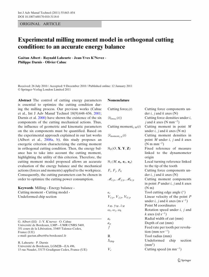
Fig. 16 Distribution of cutting power consumed
3.3 Energy balance
Moreover, it is important to recall in milling oper-ation that the complete energy balance (computedwith forces and moment cutting actions) is even moreinfluenced by cutting moments when the tool speedrotation is high (especially in the case of high-speedmachining) [5, 8]. It should also be noted radial forceFer is not often taken into account because its influencein an energy balance of a “conventional speeds” ma-chining is often erased by a low feed speed. However,in the case of high-speed machining, translation androtation speeds are more important. Therefore, it willbe necessary to take into account the six components ofcutting actions, including radial force and the momentcomponents to better calculate the real cutting powerconsumption.
Thus, in the case of milling operations, the ana-lytic expression of the total cutting power consumedis at the cutting point M in the turning reference�1(M, er, eθ , ez).
Ptot = Fer · VMer,t/w + Feθ · VMeθ,t/w + Mez/M · ωez,t/w
(10)
Therefore, with the criterion proposed, the maximalpower consumed can be evaluated with Eq. 10. The
maximal value is obtained when the cutter tooth angu-lar position is between −70◦ and −90◦.
Pmax = [Kr · V f + Kc · Vc + DM ez/M · ωez,t/w
] · Schip
(11)However, nowadays, analytical, numerical or exper-
imental cutting models do not take into account themoment influence in the energy balance.
Figure 16 shows two opposite cases for the powerconsumption. Figure 16a, b show a test where the powerconsumption by the moment is less than 10% for amill tool angular position between θ ∈ [−10◦; −170◦],whereas Fig. 16c, d show for θ ∈ [−10◦; −170◦], a mo-ment power consumption of 30% at least and up to45%. Therefore, in order to evaluate with accuracy thepower consumption, especially in high-speed milling, itis necessary to take into account the moment.
4 Conclusions and prospects
Presented tests and approaches are some parts of theunderstanding and the modelling of the cutting phe-nomena in a milling operation. Firstly, the aim is to es-tablish a complete experimental model for an industrialtool (several teeth, more complex geometry etc.), in-cluding cutting moments, to consider a comprehensive

854 Int J Adv Manuf Technol (2011) 55:843–854
energy balance. Hence, the cutting forces and momentoptimization allow to minimize spindle power consump-tion, workpiece deflection or clamping actions. Thus, theuse of an accurate complete model improves workpiecequality and reduces the cost of industrial applications.
Through the approach proposed and using specificequipment on a CNC milling machine, undeformedchip section is calculated by an original method. Thus,this calculation is based on measures in order to fit re-ality. Therefore, based on the instantaneous real unde-formed chip section, cutting densities can be computedat any time and not only in a particular milling position.
In addition, previous tests have highlighted linearevolution of radial force density D Fer and cutting forcedensity D Feθ , which confirms experimental coefficientsand cutting models as those proposed in the literature.Thus, radial and cutting force models, Fer and Feθ ,should be based on these study results. Hence, radialforce Fer and cutting force Feθ will be a linear expres-sion of real instantaneous undeformed chip sectionSchip(t), radial and cutting force densities, D Fer andD Feθ .
Thereafter, applying the proposed approach, a newexperimental indicator has been proposed: the cuttingmoment density. This criterion is developed applying asimilar approach as the cutting specific coefficients forforces. Thus, an experimental cutting moment modelfor orthogonal machining conditions is proposed.
These forces and moments energetic criteria charac-terize all of the cutting actions and allow to optimizecutting machining conditions. An essential feature ofthese criteria is to get maximum information on ma-chining operation and allows to transpose results toanother cutting operation and/or machining process.
Furthermore, cutting actions and energy balance canbe calculated through these experimental coefficientsof forces and moments. Moreover, in milling operation,the study demonstrates also the necessity to take intoaccount forces but also moments in the energy balanceto improve workpiece quality and reduce costs. Hence,in the case of high-speed machining where feed rate androtation speeds are higher, it will be necessary to takeinto account the six components of the cutting actions,including the radial force and the three moment compo-nents. Thus, the cutting power consumption estimationis more accurate. The purpose of these studies is tobetter understand some of the occurring phenomenain milling operation and especially for the cutting mo-ments. The final aim is to develop a theoretical ener-getic milling model for high cutting speed. This modelwill have to theoretically take into account the previousexperimental approach and our earlier work on turning[13] and drilling operations [7, 14].
References
1. Albert G, Cahuc O, Laheurte R, Darnis P (2007) Etude ex-périmentale de la coupe en fraisage. In: 18eme Cong. Franç.Méca. août, Grenoble
2. Albert G, Cahuc O, Laheurte R, Darnis P, K’nevez JY (2008)Approche énergétique de la coupe en fraisage. In: 5emeAssises machine et usinage à grande vitesse. Nantes, France
3. Albert G, Cahuc O, Laheurte R, Darnis P, K’nevez JY (2008)Experimental approach to develop a six components millingcutting mode. In: 16th int. conf. manuf. syst.—ICMa’S.Romania Academy of Sciences, Bucharest. pp 15–18
4. Bissey S, Poulachon G, Lapujoulade F (2005) Intégration dela géométrie d’outil dans la prédiction des efforts de coupe enfraisage grande vitesse. Méc Ind 6:391–398
5. Cahuc O, Darnis P, Gérard A, Battaglia JL (2001) Experi-mental and analytical balance sheet in turning applications.Int J Adv Manuf Technol 18(9):648–656
6. Couétard Y 1 (2000) Caractérisation et étalonnage des dy-namomètres à six composantes pour torseur associé à unsystème de forces. Thèse de Doctorat, Université Bordeaux
7. Dargnat F (2006) Modélisation semi-analytique par ap-proche énergétique du procédé de perçage de matériauxmonotithiques. Thèse de Doctorat, Université Bordeaux 1
8. Darnis P, Cahuc O, Couétard Y (2000) Energy balance withmechanical actions measurement during turning process. In:International CIRP seminar on improving machine tool per-formance. La Baule, France
9. Ding H, Chen SJ, Cheng K (2010) Two dimensionalvibration-assisted micro-milling: kinematics simulation, chipthickness computation and analysis. Adv Mater Res97(101):2779–2784
10. Fontaine M, Devillez A, Moufki A, Dudzinski D (2006) Pre-dictive force model for ball-end milling and experimentalvalidation with a wavelike form machining test. Int J MachTools Manuf 46:367–380
11. Garnier S (2000) Détermination de paramètres descriptifs del’état d’usure d’outils pour le développement d’un systèmede surveillance automatique de l’usinage en fraisage. Thèsede Doctorat, Université de Nantes
12. Garnier S, Furet B (2000) Identification of the specificcoefficients to monitor the cutting process in milling. In:International CIRP seminar on improving machine tool per-formance. La Baule, France
13. Laheurte R (2004) Application de la théorie du second gradi-ent à la coupe des matériaux. Thèse de Doctorat, UniversitéBordeaux 1
14. Laporte S (2005) Comportement et endommagement del’outil en perçage à sec: application aux assemblages aéronau-tiques. Thèse de Doctorat, Université Bordeaux 1
15. Lee P, Altintas Y (1996) Prediction of ball-end millingforces from orthogonal cutting data. Int J Mach Tools Manuf36(9):1059–1072
16. Martellotti ME (1941) An analysis of the milling process.Trans ASME 63:1667
17. Martellotti ME (1945) An analysis of the milling process. PartII: down milling. Trans ASME 67:233
18. Nuninger W, Peruquetti W, Richard JP (2006) Assessmentand stakes of the friction models: joining tribology and con-trol to achieve safety in transport. In: 5th European confer-ence on braking, vol 2. Lille, France
19. Paris H, Delhez C (2000) Modelling cutting force in high-speed milling. In: International CIRP seminar on improvingmachine tool performance. La Baule, France
20. Poirier J (1993) Analyse de la variance et de la régression.Plans d’expérience. Tech Ing R260:1–21