experimental investigations and ale finite element method
TRANSCRIPT

2245 © 2012 ISIJ
ISIJ International, Vol. 52 (2012), No. 12, pp. 2245–2253
Experimental Investigations and ALE Finite Element Method Analysis of Chatter in Cold Strip Rolling
Mohammad Reza NIROOMAND,1)* Mohammad Reza FOROUZAN,1) Mahmoud SALIMI1) and Hamid SHOJAEI2)
1) Department of Mechanical Engineering, Isfahan University of Technology, Isfahan, 84156-83111 Iran.2) Mobarakeh Steel Company, Isfahan, 84815-161 Iran.
(Received on April 24, 2012; accepted on July 23, 2012)
Chatter is the most important limitation in high speed rolling of thin strips in modern industrial cold roll-ing mills. To study chatter in rolling, it is necessary to set up models for the rolling process as well as themill stand. Existing models of the rolling process are analytic and are based on many simplifying assump-tions. In current work Arbitrary Lagrangian Eulerian (ALE) finite element method is utilized for the first timeto model the chatter vibrations in rolling, which relaxes many of these assumptions. The model has thebenefit of mass translation to computational region by using ALE technique, which tremendously reduceshuge computational requirements of the common Lagrangian models. The presented model is updatedfor simulating the chatter mechanism by means of some online velocity sensors and signal filteringmethod in applying the ALE boundary conditions. Results of the finite element model were comparedwith the experimental measurements obtained from a full scale industrial mill. Two main chattering char-acteristics, i.e., the critical rolling speed and the chatter frequency, obtained from the simulation programwere found to be in good agreement with that of the experimental measurements.
KEY WORDS: rolling; ALE finite element; chatter; experiment; vibration.
1. Introduction
During the cold rolling of thin strips, undesired mechan-ical vibration, generally referred to as chatter, is oftenobserved. It causes unacceptable gauge variation to the stripand its surface finish. It may also cause severe damage tothe rolling mill and strip rupture under extreme conditions.1)
It has also been found that as the rolling speed is increasedthe system goes to instability.1–12) As the need for low-costand high-quality products increases, prevention of chatterphenomenon becomes an important job in rolling industry.To overcome this phenomenon a deep understanding of thecause of chatter is required.
Chatter has three predominant types: torsional, thirdoctave and fifth octave.5,9,12–14) Typical frequencies of tor-sional chatter occur between 5 and 25 Hz. The third octavechatter in which the vibration frequency is usually in therange of 100 to 250 Hz often occurs in cold rolling of thinstrips. The main feature of this chattering mode is fluctua-tions in strip thickness. The fifth octave chatter, usuallyoccur in the range of approximately 500 to 700 Hz, displaysno measurable gauge variation, but the alternating light anddark lines are appeared on roll or strip surfaces.
Several theoretical researches have been conducted tomodel the chatter vibrations in rolling.1,5,9,11–16) Consequent-ly, a large number of mathematical models for the rollingprocess have been established with various degrees of sim-
plification. Similarly some researchers reported experimen-tal findings on rolling chatter.1,2,5,6,17–28)
Tamiya et al.8) proposed that the chattering phenomenonis self-excited vibration due to the phase delay between thestrip tension and vertical vibration of the work rolls basedon a study of a simplified model. Tlusty et al.9) showed thatthe periodic variation of the rolling force leads to the rollingvibrations by a 90 degrees phase. Consequently it results innegative damping and causes rising vertical oscillations ofthe rolls.
Yun et al.29) developed a suitable model for studying chat-ter. This model presents dynamic relationship between roll-ing parameters. Kimura et al.5) discovered the existence ofan optimum condition for friction in rolling. It is pointed outby Hu et al.13,30,31) that there are four significant mechanismsfor third octave chatter: model matching, negative damping,mode coupling, and regenerative. Farley et al.15) calculateda threshold rolling speed on all cold rolling mills wheregauge chatter vibration will become self-exciting.
Brusa et al.18) analyzed the dynamic effects in compactcluster mills for cold rolling numerically and experimental-ly. Their research activity was aimed to develop a methodsuitable for modeling the cold rolling chatter in cluster mills.Xu et al.11) formulated a single-stand chatter model for coldrolling by coupling the dynamic rolling process model, theroll stand structure model and the hydraulic servo systemmodel. They linearized the model and represented it as atransfer matrix in a space state. Sun et al.16) established thevibration model of the moving strip in rolling process. Theybuilt a model of distributed stress based on rolling theory
* Corresponding author: E-mail: [email protected]: http://dx.doi.org/10.2355/isijinternational.52.2245
© 2012 ISIJ 2246
ISIJ International, Vol. 52 (2012), No. 12
and then conducted a vibration model of moving strip withdistributed stress.
In this research the ALE finite element method was usedfor the first time to study the vibration of rolling mills inorder to improve the rolling process sub model. This modelis more accurate than those of the previous analytical mod-els by relaxing many simplifying assumptions. Using thistechnique the computational cost is reduced tremendously incomparison to that of the usual Lagrangian method. Finally,experimental measurements are used to show the accuracy,robustness and usefulness of the proposed model.
2. Finite Element Model
2.1. Geometrical and Material PropertiesMany different modes of chatter and their possible causes
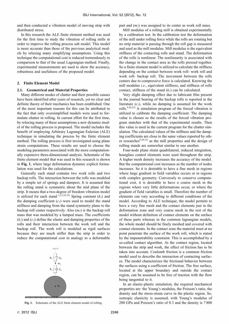
have been identified after years of research, yet no clear anddefinite theory of their mechanics has been established. Oneof the most important reasons for this can be attributed tothe fact that only oversimplified models were used to for-mulate chatter in rolling. In current effort for the first time,by relaxing many of these assumptions a new dynamic mod-el of the rolling process is proposed. The model includes thebenefit of employing Arbitrary Lagrangian Eulerian (ALE)technique in simulating the process by the finite elementmethod. The rolling process is first investigated using planestrain computations. These results are used to choose themodeling parameters associated with the more computation-ally expensive three-dimensional analysis. Schematic of thefinite element model that was used in this research is shownin Fig. 1, where large deformation dynamic explicit formu-lation was used for the calculations.
Generally each stand contains two work rolls and twobackup rolls. The interaction between the rolls was modeledby a simple set of springs and dampers. It is assumed thatthe rolling stand is symmetric about the mid plane of thestrip. It means that a two-degree of freedom vibration modelis utilized for each stand.1,2,5,32,33) Spring constant (k1) andthe damping coefficient (c1) were used to model the standstiffness and damping from the stand symmetry plane to thebackup roll center respectively. Also (m1) is the backup rollmass that was modeled by a lumped mass. The coefficients(k2) and (c2) define the elastic and damping properties of therolls and their interaction between the work roll and thebackup roll. The work roll is modeled as rigid surfacesbecause they are much stiffer than the strip in order toreduce the computational cost in analogy to a deformable
part and (m2) was assigned to its center as work roll mass.Mill modulus of a rolling mill is obtained experimentally
by a calibration test. In the calibration test the deformationof the mill under rolling force while the rolls are rotating butno strip material is passing through the roll gap is measuredand used as the mill modulus. Mill modulus is the equivalentstiffness of the contacting rolls and stand. The deformationof the rolls is nonlinear. The nonlinearity is associated withthe change in the contact area as the rolls pressed together.So a finite element model is utilized to calculate the stiffnessdepending on the contact between work roll- work roll andwork roll- backup roll. The movement between the rollscenters due to compressive force is calculated. Knowing themill modulus i.e., equivalent stiffness, and stiffness of rollscontact, stiffness of the stand (k1) can be calculated.
Very slight damping effect due to lubricant film presentin the journal bearing of the backup rolls is reported in theliterature (c1), while no damping is assumed for the workrolls.9,30,32) A simulation program of the forced vibration isutilized to calibrate the damping coefficient. The dampingvalue is chosen so the results of the forced vibration pro-gram matches with that of the experimental results. Thenthis value is used in the current program for the chatter sim-ulation. The calculated values of the stiffness and the damp-ing coefficients are close to the same values reported by oth-er researches9,30,32) as the mill properties and the design ofrolling stands are somewhat similar to one another.
Four-node plane strain quadrilateral, reduced integration,hourglass control elements were used throughout the strip.A higher mesh density increases the accuracy of the model.But the computational cost increases as the number of nodesincreases. So it is desirable to have a fine mesh in regionswhere large gradient in field variables occurs or in regionswith complex geometry. Conversely to conserve computa-tional cost, it is desirable to have a course mesh in theregions where very little deformations occur, or where thegradient of field variables is small. Therefore the number ofelements can vary according to different conditions of themodel. According to ALE technique, the model permits tohave a very fine mesh and the contact elements just in thedeformation zone and very coarse mesh in the rest of themodel without definition of contact elements on the surfaceof these parts whereas in the common lagrangian models,the whole model should be finely meshed and covered withcontact elements. In the contact zone the material must at nopoint penetrate the surface of the work roll, which is statedby the impenetrability constraint. This is accomplished by aso-called contact algorithm. At the contact region, locatedbetween the strip and work, the effect of friction has to betaken into account. Coulomb friction is a common frictionmodel used to describe the interaction of contacting surfac-es. The model characterizes the frictional behavior betweenthe surfaces using a coefficient of friction. The free surface,located at the upper boundary and outside the contactregion, can be assumed to be free of traction with the flowbeing tangential to it.
In an elastic-plastic simulation, the required mechanicalproperties are: the Young’s modulus, the Poisson’s ratio, thedensity and the stress-strain curve in the plastic region. So,isotropic elasticity is assumed, with Young’s modulus of200 GPa and Poisson’s ratio of 0.3 and the density is 7 800Fig. 1. Schematic of the ALE finite element model of rolling.

ISIJ International, Vol. 52 (2012), No. 12
2247 © 2012 ISIJ
kg/m3. The flow stress, instantaneous yield stress at whichworkpiece material starts to flow, is dependent of the effec-tive strain. The flow stress equation for the material used inthis paper is given by a power law:
σ = 709.6 (2.08 + ε )0.362
where σ is the effective stress and ε is the effective strain.The strain hardening equation is applied to the model using15 points on the yield stress versus plastic strain curve. Norate dependence or temperature dependence is taken intoaccount.
Parameters for the mill stand configuration and materialproperties in this research were taken from a two-stand tan-dem mill unit of Mobarakeh Steel Company (MSC) and ispresented in the next section.
2.2. Initial and Boundary ConditionsAs mentioned earlier, four significant mechanisms have
been introduced for the third octave chatter. In this researchthe single stand negative damping mechanism was imple-mented in the finite element model. Negative damping ispossibly the most direct cause to the process leading to theonset of the third octave mode chatter in a single-stand roll-ing. As pointed out in many literature sources9,12–14) tensionvariations caused by mill vibrations generate roll force vari-ations which, in turn, induce further vibrations, and thus canbe viewed as a negative damping effect.
To start the rolling process, the strip must have an appro-priate initial velocity in the rolling direction. Therefore aninitial velocity field was applied to entire sheet. Accordingto low rotational frequency of payoff and pickup reels it isassumed that they do not introduce any velocity variationsto the strip at entry to or exit from the roll gap.5,9,14,18,34,35)
Variation in tension directly depends on the stiffness of thestrip at entry to or exit from the roll gap which is a linearfunction of the strip length. Therefore a single stand nega-tive damping model could be attained by applying a con-stant velocity as the boundary condition both for entry andexit material as shown in Fig. 1.9,12–14,33) Other boundarycondition of the model is constant angular velocity for thework roll. A ramped downward displacement is applied tothe upper point of spring and damper number 1 in Fig. 1.Having the specific reduction, the required amount of down-ward displacement can be calculated easily. This displace-ment simulates the screw down in rolling that controls theroll gap. Also a symmetry B. C. is used for the symmetryhorizontal line on the lower nodes of the strip. But the mainproblem is to find the entry or exit velocities. For this pro-pose a key technology of using some online velocity sensorsand signal filtering method in applying the ALE boundaryconditions is utilized for the first time.
A subroutine was developed and used to specify the asso-ciated velocity boundary conditions. Moreover, online sen-sors were used to define the solution-dependent amplitudeof the boundary condition. This technique is needed to mod-el the control engineering aspects of the system. Sensor val-ues are taken from the beginning of the increment. The solu-tion dependence introduced in the subroutine is explicit, i.e.,all data passed to the subroutine are values at the beginningof that increment.
In this subroutine, the entrance velocity of the input strip
to the roll gap is measured by some sensors during the sim-ulation. There are five nodes within the thickness of thestrip. The velocity of the strip at each node is measured bya sensor. Then the average value of these velocities is usedas the entrance velocity of material to the roll gap. The aver-age value is processed in the subroutine to obtain the appro-priate boundary condition.
The exit velocity of the payoff reel was set equal to themean entry velocity to the roll gap multiplied by a multiplier(η) very close to unity. This multiplier controls the desiredentry tension. Evidently for increasing inter-stand tension ittakes values of less than unity and vice versa. The entrancevelocity of the input strip to the roll gap is measured by asensor during the simulation. Measured velocity was filteredby a low-pass filter (LPF) to obtain the mean velocity. Sim-ilar technique is used for the exit side to set the entry veloc-ity to the pickup reel which is equal to the mean exit veloc-ity of the current stand. This technique is shown in Fig. 2schematically.
The filter that is used in the model is an online first-orderlow-pass filter (LPF). The input to the filter is the sensedvelocity and the output of the filter is the moving averageof it. The transfer function of LPF is presented in Eq. (1):
.............................. (1)
where ω p is the cutoff frequency of the filter. The cutoff fre-quency should be selected carefully in designing a filter. Itshould be adjusted such that the filter eliminates the high-frequency signals but follows the moving average of thevelocity due to the low-frequency variation in rolling con-ditions. So the cutoff frequency is set to 20 Hz.
The effect of a LPF can be simulated on a computer byanalyzing its behavior in a digital form, and then discretiz-ing the model. In digital signal processing a complex fre-quency domain (s-domain) equation can be converted intoa complex discrete-time-frequency domain (z-domain). Thetransfer function of the digital filter in z-domain can beobtained as:
.................... (2)
where fsample is the sampling frequency. For implementationof Eq. (2), it should be used in its discrete-time domain formas follows:
Fig. 2. Schematic show of implementation of negative dampingmechanism.
H ss
p
( ) =+
1
1ω
H zf
zsample
p
( )
( )
−
−
=+ −
1
1
1
1 1ω

© 2012 ISIJ 2248
ISIJ International, Vol. 52 (2012), No. 12
................... (3)
where u(k) and y(k) are the input and output of the filter atkth sampling. It should be noted that time increments varyduring the finite element analysis. So fsample was set to theinverse of the time increment and was updated for everytime increment during the solution.
2.3. Benefits of the ALE Formulation in Chatter Simu-lation
ALE technique is considered as the key technology toachieve an applicable finite element model for modeling thechatter phenomenon in rolling. It is debt to the ability of theALE technique in modeling material flow to or from thecomputational region. Theoretically an ALE-FE model maycontain just few centimeters of the strip in the deformationzone. Following benefits were achieved by using the ALEtechnique as a replacement for the Lagrangian formulation;
1) Tremendous reduction in DOF of the computationalmodel from the viewpoint of the region which needs finemesh.
2) Tremendous reduction in computational requirementsin perspective of the required contact elements.
3) Negative damping mechanism can be implementedcarefully by using the ALE method. In this method velocityand tension boundary conditions may be applied correctlyusing the online sensors and filters.
Despite modeling of the plastic deformation in the rollgap that requires few centimeters of the strip to be modeledbut, it is found that, the elastic properties of the strip outsideof the roll gap have essential effect on the chattering ofstand. Therefore it is important to model the strip in threeparts; 1) from its separation point of the payoff reel to theroll gap (4.725 m), 2) within the roll gap (4 cm) and 3) formthe roll gap to the connection point to the pickup reel (6.6m). Fortunately the additional parts can be meshed quitecourse. These parts need to simulate change in forward andbackward tensions via elastic wave transmission in the stripso do not change the total DOF of the model considerably.
Mesh motion treatment is one of the most important fea-tures of any ALE finite element solution. In here; the finiteelement mesh of the strip is Eulerian in horizontal directionand Lagrangian in vertical direction. It is clear that the num-
ber of the degree of freedom of the proposed model frompayoff reel to the pickup reel is thousands times less than acommon Lagrangian model. It reduces the computationalcosts tremendously. Considering the required very smalltime increment in modeling the process the benefits ofemploying ALE in this problem is appreciated.
3. Experimental Equipment
This section presents the experimental investigations ofthe third octave chatter on a two-stand tandem mill unit ofMobarakeh Steel Company (MSC). Figure 3 shows a viewof this unit.
Incoming coils to this unit are often 2 mm in thickness.They open up and pass through two 4-high stands two orthree times. Usually thicknesses of the strip are reduced by60 to 90 percents depending on the desired thickness. Out-going strip from the second stand in any pass is coiled by aPickup reel. The pickup reel of the previous pass plays roleof the payoff reel for the current pass which is in the reversedirection of the previous pass. In practice in this mill, chatterusually occurs in second stand during the third pass.
Rolling control instrumentation in two-stand tandem millunit consists of tens analog and digital signals, all connectedwith a data collection system (IBA). All rolling conditionsare recorded in this system and can be used online or offline.To evaluate the status of the rolling system in chatter con-ditions, rolling speed was increased for the moment. This isdone by the operator via online monitoring system. Specifi-cations of the rolling mill under consideration are presentedin Table 1. It also presents the conditions of the rolling pro-cess in the third pass. Inter-stand parameters are presentedin Table 2.
Fig. 3. Two-stand tandem mill unit of Mobarakeh Steel Company.
y k
fy k u k
f
sample
p
sample
p
( )
( ) ( )
=− +
+
ω
ω
1
1
Table 1. Specifications of two-stand tandem mill unit.
Parameter Stand 1 Stand 2
Work roll mass (Kg) 14 000 14 000
Backup roll mass (Kg) 38 000 38 000
Work roll damping coefficient (N.s/m) 0 0
Backup roll damping coefficient (N.s/m) 9.54e5 9.54e5
Work roll spring constant (N/m) 7.01e10 7.01e10
Backup roll spring constant (N/m) 3.64e8 3.64e8
Work roll radius (m) 0.245 0.245
Backup roll radius (m) 0.675 0.675
Friction coefficient 0.012 0.010
Strip width (m) 0.819 0.819
Entry thickness (m) 537e-6 399e-6
Exit thickness (m) 399e-6 280e-6
Table 2. Inter-stand parameters of the two-stand tandem mill unit.
Parameter Payoff real-Stand 1
Stand 1-Stand2
Stand 2-Pickup real
Distance (m) 5.675 4.725 6.6
Tensile Stress (MPa) 96 141 77

ISIJ International, Vol. 52 (2012), No. 12
2249 © 2012 ISIJ
4. Results and Discussions
4.1. VerificationTo ensure that the boundary conditions are applied cor-
rectly, the graph of the tensions and the velocities are shownin Fig. 4.
It can be seen that the backward and forward tensions arevary about the desired values. Also the filtered velocitiesfollow the moving average of the sensed velocities andeliminate their fluctuations. Therefore, the filters work asexpected.
Also, rolling force can be used as a criterion to verify thevalues selected as rolling and mill parameters. Figure 5shows the rolling force calculated using the finite elementmodel.
Calculated rolling force is compared with that of theexperimental one. Experimental rolling force is recordedwith the data collection system. Figure 6 shows the varia-tion of rolling force for the given coil for the duration ofthree passes. Third pass started from approximately 600th
second. It can be seen that the rolling force is higher in thethird pass than the two previous passes and is about 780MN. It is evident that the calculated rolling force is in goodagreement with the measured experimental rolling force.
4.2. Rolling VibrationsTwo main characteristics of chatter are rolling critical
speed and chatter frequency. These parameters have been
used to compare the simulation and experimental results.So, the finite element model was run with the same condi-tion of the experimental settings. By increasing the rollingspeed, it is expected that the system goes to instability.1–12)
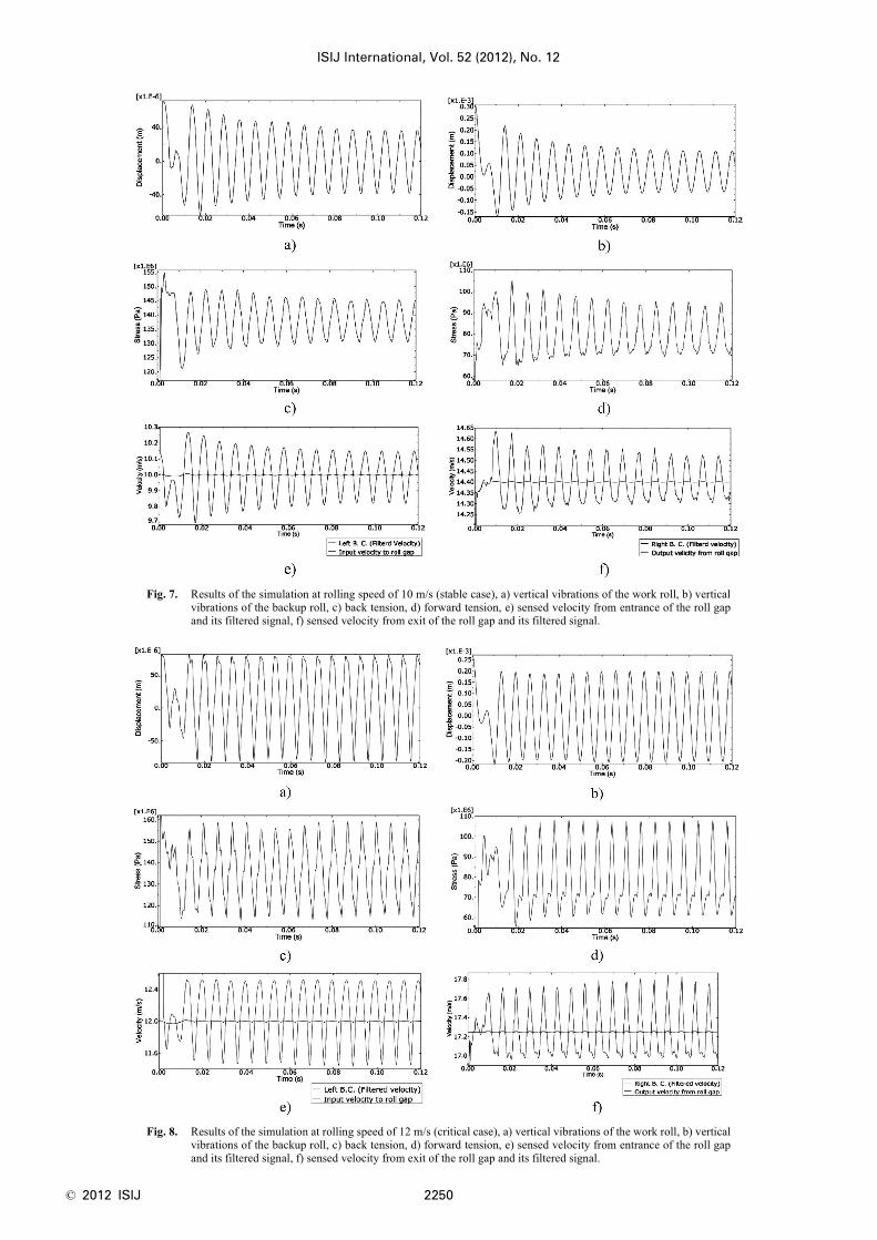
To investigate the effect of rolling speed three differentcases were examined. Figure 7 shows the results of the sim-ulation model in the first case. In this case the incoming stripspeed was set to 10 m/s. As it can be seen the vibrations ofrolls are damped. It is concluded that the system is stable inthis case. This is an example of rolling in a subcritical speed.Variations of the backward and forward tension and entryand exit velocity to the roll gap are shown in the figure. Alsothe filtered signals that are used as left and right boundaryconditions are presented in the figure.
By increasing the strip speed to 12 m/s, the vertical vibra-tions are not damped and the vibrations amplitude remainsconstant over time. So in this case the speed is critical.Figure 8 shows the results of the simulation model in thecritical speed.
By increasing the speed to 14 m/s the vibrations ampli-tude is increased by the time and the system becomes unsta-ble. Figure 9 shows the results of the simulation model inthis case. It is obvious that the vibration domain is increas-ing which is known as the chatter or unstable vibration.
Variations of the rolling force and the work roll vibrations
Fig. 4. Evaluation of correctness of boundary conditions, a) back tension, b) forward tension, c) sensed velocity fromentrance of the roll gap and its filtered signal, d) sensed velocity from exit of the roll gap and its filtered signal.
Fig. 5. Calculated rolling force using finite element model.
Fig. 6. Measured rolling force during three passes recorded in thedata collection system.
© 2012 ISIJ 2250
ISIJ International, Vol. 52 (2012), No. 12
Fig. 7. Results of the simulation at rolling speed of 10 m/s (stable case), a) vertical vibrations of the work roll, b) verticalvibrations of the backup roll, c) back tension, d) forward tension, e) sensed velocity from entrance of the roll gapand its filtered signal, f) sensed velocity from exit of the roll gap and its filtered signal.
Fig. 8. Results of the simulation at rolling speed of 12 m/s (critical case), a) vertical vibrations of the work roll, b) verticalvibrations of the backup roll, c) back tension, d) forward tension, e) sensed velocity from entrance of the roll gapand its filtered signal, f) sensed velocity from exit of the roll gap and its filtered signal.

ISIJ International, Vol. 52 (2012), No. 12
2251 © 2012 ISIJ
in the three cases are shown in Fig. 10.As pointed out in many literature sources9,12–14) tension
variations caused by mill vibrations generate roll force vari-ations which, in turn, induce further vibrations, and thuscomplete the vibration loop. It should be noted that the peri-odic variation of the roll force leads the mill vibrations. Ifthere is a phase difference in a loop then it will go unstableas the gain is increased above a certain value. Accordingthat the gain is proportional to the speed of the strip in therolling, it is explained why rolling mills goes to instabilityas the speed is increased above a threshold value. This feed-back loop that exists in every mill stand explains the poten-tial to cause self-excited vibrations. As can be seen from theFig. 10, the mean value of the tensions is equal in all cases.But tension variations diverge when the rolling speed isgreater than the threshold value.
Figure 11 shows the Fast Fourier Transform (FFT) of thevibration signals in the unstable case. The peak of these dia-grams occurs at 141 Hz. It is in the range of third-octavechatter frequency and should be compared with the experi-mental observations.
It is obvious from Fig. 11 that the FFT spectrum of thework roll shows the harmonics of the chatter frequency inaddition to the fundamental frequency of chatter. The back-up roll vibration signal has only one prominent frequencythat lies in the range of the third octave chatter.
In order to investigate the finite element model, chattertest was carried out experimentally in the two-stand tandemmill unit. To evaluate the status of the rolling system in chat-ter condition, rolling speed was increased for the moment.
Fig. 9. Results of the simulation at rolling speed of 14 m/s (unstable case), a) vertical vibrations of the work roll, b) verti-cal vibrations of the backup roll, c) back tension, d) forward tension, e) sensed velocity from entrance of the rollgap and its filtered signal, f) sensed velocity from exit of the roll gap and its filtered signal.
Fig. 10. Variations of the rolling force and the work roll vibra-tions, a) stable case, b) critical case, c) unstable case.

© 2012 ISIJ 2252
ISIJ International, Vol. 52 (2012), No. 12
This work has been done by the operator via online moni-toring system. Upon the occurrence of chatter rolling speedwas reduced by the operator in order to prevent the strip rup-ture. Reducing the rolling speed reduces the vibration.
Figure 12 shows the variation of rolling speed over timefor the considered coil. It can be seen that the rolling speedis zero at the beginning and end of each pass. Thus each ofthe three pass is recognizable easily in this figure. Theexperiment is carried out during the third pass. Chatter con-ditions occurred two times in this process at 820th and 920th
seconds. The rolling speed has suddenly decreased at thesetimes to prevent damage to stand or strip.
The stand is equipped with a permanent accelerometerwhich is fixed on the top housing of the second stand.Figure 13 shows the amplitude of the recorded accelerationsignal and its FFT spectrum during the third pass. It can beseen that the acceleration amplitude is lower at the begin-ning and the end of rolling. Rolling speed in these regionsis lower than other points, hence an increase in rolling speedresults in higher values oscillations.36)
Since the FFT applied to the total time range of the thirdpass (about 500 sec.), the frequency response does not showthe chatter frequency clearly. So the FFT should be appliedto the acceleration signal in the time range of chatter.
The previous figure is expanded in Fig. 14(a) at the chat-ter time range. FFT spectrum of the acceleration signal hasbeen shown in Fig. 14(b). It is shown that the peak of thefrequency spectrum occurs at 139 Hz, which is in the range
Fig. 12. Variation of rolling speed over time for the considered coil.
Fig. 11. FFT spectrum of the vibration signals in the unstable case, a) work roll, b) backup roll.
Fig. 13. Vertical vibrations of the top housing during the third pass, a) acceleration signal, b) FFT spectrum.
Fig. 14. Vertical vibrations of the top housing in the time range of chatter, a) acceleration signal, b) FFT spectrum.

ISIJ International, Vol. 52 (2012), No. 12
2253 © 2012 ISIJ
of the third-octave chatter frequency.The FFT spectrum of the work and backup rolls is pre-
sented in Fig. 15. It is obvious that similar to the simulationresults, harmonics of the chatter frequency appears only inthe FFT spectrum of the work roll.
There are some evidences that verify the model: first ofall the model is sensitive to the rolling speed and goes toinstability by increasing the rolling speed. The second con-firmation is the chattering frequency which is found to be141 Hz in simulation and 139 Hz in experiment. These num-bers match well and are within the range of the third octave.Also the FFT spectrum of the work and backup rolls exper-imental results well matches that of the simulation ones.
5. Conclusion
Chatter mechanism in rolling was implemented success-fully by the ALE-FE technique. The proposed methodreduces many computational requirements of the commonFE models while relaxes many assumptions of the earlieranalytical models. Using this method cold rolling of thinsteel strips was simulated in subcritical, critical and super-critical chatter speeds. In subcritical speed the initial excita-tions were damped. In the critical speed the fluctuationswere never damped and in the last case the vibration domainwas increasing which is known as the chatter or unstablevibration. Simulation results are in comprehensive agree-ment with the experimental observations. The proposedmodel may be used to determine the limiting rolling speed,safe against the chatter vibrations. Therefore it can increasethe productivity of the rolling machine while preserving thequality of the produced sheet. Using this novel model in pre-dicting the chatter in rolling, effect of each parameter onrolling condition can be studied and some suggestions tostabilize the rolling system can be presented more reason-ably.
AcknowledgmentThe authors are grateful for the assistance of the Mobarakeh
Steel Company.
REFERENCES
1) P. A. Meehan: J. Vib. Acoust., 124 (2002), 221.2) L. Chefneux, J.-P. Fischbach and J. Gouzou: Iron Steel Eng., 61
(1984), 17.
3) Z. Drzymala, A. Swiatoniowski and A. Bar: Mécanique Industries, 4(2003), 151.
4) P.-H. Hu and K. F. Ehmann: Technical Paper - Soc. Manuf. Eng. MF,MF99-156 (1999), 1.
5) Y. Kimura, Y. Sodani, N. Nishiura, N. Ikeuchi and Y. Mihara: ISIJInt., 43 (2003), 77.
6) T. Kong and D. C. H. Yang: P. I. Mech. Eng. E.- J. Pro., 207 (1993),143.
7) Y.-J. Lin, C. S. Suh and S. T. Noah: Proc. of ASME Int. MechanicalEngineering Cong. Exposition, ASME, New York, (2002), 323.
8) T. Tamiya, K. Furui and H. Iida: Proc. of Mineral Waste UtilizationSymp., Vol.2, ISIJ, Tokyo, (1980), 1191.
9) J. Tlusty, G. Chandra, S. Critchley and D. Paton: Annal. CIRP, 31(1982), 195.
10) Y. X. Wu and J. A. Duan: J. Mater. Process. Technol., 129 (2002),148.
11) X. Yang, C.-n. Tong, G.-f. Yue and J.-j. Meng: J. Iron Steel Res. Int.,17 (2010), 30.
12) I. S. Yun, W. R. D. Wilson and K. F. Ehmann: Int. J. Mach. ToolManuf., 38 (1998), 1499.
13) P.-A. Hu, H. Zhao and K. F. Ehmann: P. I. Mech Eng. E.-J. Pro., 220(2006), 1267.
14) H. Zhao and K. F. Ehmann: Proc. of ASME Int. Manufacturing Sci-ence Engineering Conf., ASME, New York, (2009), 627.
15) T. Farley: Light Metal Age, 64 (2006), 12.16) J.-l. Sun, Y. Peng and H.-m. Liu: J. Iron Steel Res. Int., 17 (2010), 11.17) T. Barszcz and A. JabLonski: Mech. Syst. Signal Process., 25 (2011),
431.18) E. Brusa and L. Lemma: J. Mater. Process. Technol., 209 (2009),
2436.19) E. Brusa, L. Lemma and D. Benasciutti: P. I. Mech Eng. E.-J. Pro.,
224 (2009), 1645.20) Z. Kiral and H. Karagülle: Tribol Int., 36 (2003), 667.21) Y. D. Makarov, E. G. Beloglazov, I. V. Nedorezov and T. A.
Mezrina: Steel Transl., 38 (2008), 1040.22) S. Orhan, N. Aktürk and V. Çelik: NDT&E Int., 39 (2006), 293.23) J. W. Perng, W. T. Tseng, K. W. Han, S. J. Tsai and C. H. Lin: J.
Franklin Inst., 335 (1998), 679.24) B. Petit, D. Decrequy, A. Jakubowski, F. Bertolini, J. Perret and S.
Gouttebroze: Rev. Metall.-CIT, 102 (2005), 535.25) N. Sawalhi and R. B. Randall: Mech. Syst. Signal Process., 25 (2011),
846.26) E. A. Unver: Proc. of the International Modal Analysis Conf. &
Exhibit, Union College, Schenectady, (1984), 648.27) I. Yarita, K. Furukawa, Y. Seino, T. Takimoto, Y. Nakazato and K.
Nakagawa: Kawasaki Steel Tech. Rep., 18 (1978), 1.28) J. Zhong, H. Yan, J. Duan, L. Xu, W. Wang and P. Chen: J. Mater.
Process. Technol., 120 (2002), 275.29) I. S. Yun, W. R. D. Wilson and K. F. Ehmann: J. Manuf. Sci. E-T
ASME, 120 (1998), 330.30) P.-H. Hu, H. Zhao and K. F. Ehmann: P. I. Mech Eng. E.-J. Pro., 220
(2006), 1279.31) P.-H. Hu, H. Zhao and K. F. Ehmann: P. I. Mech Eng. E.-J. Pro., 220
(2006), 1293.32) R. E. Johnson and Q. Qi: Int. J. Mech. Sci., 36 (1994), 617.33) I. S. Yun, K. F. Ehmann and W. R. D. Wilson: ASME J. Manuf. Sci.
Eng., 120 (1998), 343.34) J. Niziol and A. Swiatoniowski: J. Mater. Process. Technol., 162-
163 (2005), 546.35) M. A. Younes, M. Shahtout and M. N. Damir: J. Mater. Process.
Technol., 171 (2006), 83.36) A. Bar and A. Swiatoniowski: J. Mater. Process. Technol., 155-156
(2004), 2116.
Fig. 15. FFT spectrum of the acceleration signal in the time range of chatter, a) work roll, b) backup roll.