experimental investigation of the minimum · pdf filesemasa pemesinan aloi aluminium 6061-t6...
TRANSCRIPT

EXPERIMENTAL INVESTIGATION OF THE MINIMUM QUANTITY
LUBRICATION IN END-MILLING OF AA6061T6 BY COATED CARBIDE TOOLS
ABDUL MUHAIMIN BIN ARIS
Report submitted in partial fulfillment of requirements
for award of the Degree of
Bachelor of Mechanical Engineering
Faculty of Mechanical Engineering
UNIVERSITI MALAYSIA PAHANG
JUNE 2013
vii
ABSTRACT
This report presents an experimental investigation on the effects of output
parameters which are surface roughness, tool wear and material removal rate during
machining aluminum alloy 6061-T6 using minimum quantity lubricant (MQL)
technique. The minimum quantity of lubrication technique is becoming increasingly
more popular due to the safety of environment. The cutting speed, depth of cut, feed rate
and MQL flow rate are selected input parameters in this study. This experiment was
conducted based on central composite design method. To develop a model of process
optimization based on the response surface method. MQL parameters include nozzle
direction in relation to feed direction, nozzle elevation angle, distance from the nozzle
tip to the cutting zone, lubricant flow rate and air pressure. To achieve a maximum
output parameters based on the optimized process parameters for coated carbide cutting
tools (CTP 2235). The surface roughness was increased with decrease of cutting speed.
The optimum cutting condition for MQL and flooded are obtained the feed rate, depth
of cut, cutting speed and MQL flow rate are 379 mm/tooth, 2 mm, 5548.258 rpm and
0.333 ml/min respectively for MQL. The optimum cutting condition for flooded are
obtained the feed rate, depth of cut, cutting speed and MQL flow rate are 379 mm/tooth,
2 mm and 5563.299 rpm respectively for flooded. It is seen that a majority of coated
carbide inserts have a long tool wear when exposed to high cutting speed, and feed rate
leading to breakage of the inserts.

viii
ABSTRAK
Laporan ini membentangkan siasatan ujikaji mengenai kesan parameter
pengeluar iaitu kekasaran permukaan, pemakaian alat dan kadar penyingkiran bahan
semasa pemesinan aloi aluminium 6061-T6 menggunakan minimum kuantiti pelincir
(MQL) teknik. Teknik minimum kuantiti pelinciran menjadi semakin popular kerana
keselamatan alam sekitar. Kelajuan pemotongan, kedalaman pemotongan, ‘feed rate’
dan kadar aliran MQL dipilih menjadi parameter kemasukan dalam kajian ini.
Eksperimen ini telah dijalankan berdasarkan reka bentuk komposit pusat kaedah. Untuk
membentuk model pengoptimuman berdasarkan kaedah gerak balas permukaan.
Parameter MQL termasuk arah muncung berhubung dengan makanan haiwan arah,
sudut ketinggian jarak muncung dari hujung muncung ke zon pemotongan, kadar aliran
pelincir dan tekanan udara. Untuk mencapai parameter pengeluar maksimum
berdasarkan proses parameter dioptimumkan untuk bersalut alat pemotong karbida
(CTP 2235). Kekasaran permukaan telah meningkat dengan penurunan kelajuan
pemotongan. Keadaan pemotongan optimum untuk MQL dan ‘flooded’ diperolehi ‘feed
rate’, kedalaman potongan, kelajuan pemotongan dan kadar aliran MQL adalah 379
mm/gigi, 2 mm, 5548,258 rpm dan 0.333 ml/min masing-masing untuk MQL. Keadaan
pemotongan optimum untuk ‘flooded’ diperolehi ‘feed rate’, kedalaman potongan,
kelajuan pemotongan dan kadar aliran MQL adalah 379 mm/gigi, 2 mm dan 5563,299
rpm masing-masing untuk ‘flooded’. Ia dilihat bahawa majoriti ‘insert’ bersalut karbida
mempunyai pemakaian alat yang lama apabila terdedah kepada kelajuan pemotongan
yang tinggi, dan ‘feed rate’ yang membawa kepada kerosakan kepada ‘inserts’.
ix
TABLE OF CONTENTS
Page
EXAMINER’S DECLARATION ii
SUPERVISOR’S DECLARATION iii
STUDENT’S DECLARATION v
ACKNOWLEDGEMENTS vi
ABSTRACT vii
ABSTRAK viii
TABLE OF CONTENTS ix
LIST OF TABLES xii
LIST OF FIGURES xiii
LIST OF SYMBOLS xv
LIST OF ABBREVIATIONS xvi
CHAPTER 1 INTRODUCTION
1.1 Introduction 1
1.2 Problem Statement 2
1.3 Objectives of the project 3
1.4 Project scope 3
1.5 Organization of the project 4
CHAPTER 2 LITERATURE REVIEW
2.1 Introduction 5
2.2 Milling Machine 5
2.2.1 Type of Milling Machine 6
2.2.2 End Milling Machine 8
2.2.3 Operation of Milling Machine 9
2.3 Coated Carbide Tools 9
2.4 Minimum Quantity Lubrication 10
2.5 Aluminum Alloy 11

x
2.6 Process Parameters 11
2.6.1 Cutting Speed 12
2.6.2 Feed Rate 13
2.6.3 Axial Depth of Cut 14
2.7 Response Parameters 15
2.7.1 Tool Wear 15
2.7.2 Surface Roughness 17
2.7.3 Material Removal Rate 18
2.8 Summary 18
CHAPTER 3 METHODOLOGY
3.1 Introduction 19
3.2 Materials Properties 20
3.3 Cutting tool 22
3.4 Machining Parameters 23
3.4.1 Input Parameters 24
3.4.2 Output Parameters 25
3.5 Experiment Set Up 29
3.6 Data Collection 31
3.7 Summary 32
CHAPTER 4 RESULTS AND DISCUSSION
4.1 Introduction 33
4.2 Machining Parameters and Design of Experiments 33
4.3 Surface Roughness 34
4.3.1 Mathematical modelling 34
4.4 Material Removal Rate 42
4.4.1 Mathematical modelling 42
4.5 Tool Wear 47
4.5.1 Mathematical modelling 47
4.6 Optimization Value 53
4.7 Summary 54

xi
CHAPTER 5 CONCLUSION AND RECOMMENDATIONS
5.1 Introduction 55
5.2 Conclusion 55
5.3 Recommendations 56
REFERENCES 57

xii
LIST OF TABLES
Table No. Title Page
3.1 Chemical composition of the aluminum alloy 6061-T6 21
3.2 Composition of the coated carbide inserts 22
3.3 Parameters for MQL Machining. 23
3.4 Input and output parameters 24
3.5 The specification for CNC milling machine HAAS VF-6 30
4.1 Design of Experiment Matrix for MQL 34
4.2 Design of Experiment Matrix for flooded 34
4.3 Variance analysis for the second order model of the surface roughness
MQL and flooded
36
4.4 Experimental and predicted results second order model RSM of surface
roughness for MQL
37
4.5 Experimental and predicted results second order model RSM of surface
roughness for flooded
38
4.6 Variance analysis for second orders MRR for MQL and flooded 43
4.7 Experimental results RSM second order material removal rate predicted
values for flooded
45
4.8 Experimental results RSM second order material removal rate predicted
values for MQL
46
4.9 Variance analysis for second orders tool wear for MQL and flooded 48
4.10
Experimental and predicted results second order model RSM of tool wear
for flooded
49
4.11 Experimental and predicted results second order model RSM of tool wear
for MQL
51
4.12 The optimization of MQL and flooded for coated carbide inserts 53

xiii
LIST OF FIGURES
Figure No. Title Page
2.1 Vertical milling machine 7
2.2 Horizontal milling machine 7
2.3 End milling process 8
2.4 Different operation of miling machine 9
2.5 End milling (Milling machine) operation. 15
2.6 The comparison of the tool wear for different cutting processes 16
3.1 Flow chart of the study 20
3.2 Workpiece block. 21
3.3 Tool holder and cutting tool insert and insert coated carbide tool 25
3.4 Graph position for average roughness (Ra) 26
3.5 Tool wear depend on the technique use. 26
3.6 The movement of tool in horizontal milling machine. 28
3.7 The movement of tool in vertical milling machine. 29
3.8 CNC milling machine HAAS VF-6 29
3.9 Portable roughness tester model MarSurf PS1 31
3.10 Optical video measuring system 32
4.1 Image of surface roughness for maximum cutting speed MQL and
flooded
38
4.2 Image of surface roughness for maximum feed rate MQL and flooded 39
4.3 Image of surface roughness for maximum depth of cut MQL and
flooded
39
4.4 Surface roughness versus MQL 40
4.5 Surface roughness versus feed rate using (a) MQL (b) flooded 41

xiv
4.6 Surface roughness versus depth of cut for (a) MQL (b) flooded 41
4.7 Surface roughness versus cutting speed for (a) MQL (b) flooded 42
4.8 MRR versus depth of cut for (a) MQL (b) flooded 44
4.9 MRR versus feed rate for (a) MQL (b) flooded 46
4.10 MRR versus cutting speed for MQL (b) flooded 47
4.11 Image of tool wear (a) MQL (b) flooded 50
4.12 Tool wear versus MQL flow rate 50
4.13 Tool wear versus feed rate for (a) MQL (b) flooded 52
4.14 Tool wear versus depth of cut for (a) MQL (b) flooded 52
4.15 Tool wear versus cutting speed for (a) MQL (b) flooded 53

xv
LIST OF SYMBOLS
RPM Revolution per minute
vc cutting speed
rf feed rate in mm/rev
ft Feed rate in mm/tooth
n Number of the teeth of cutter
Ra Average surface roughness
L Sampling length
Y Ordinate of the profile curve
V Cutting speed
T Tool life (minutes)
C Taylor’s constant for the unaccounted variables
N RPM of Cutter
W Width of cut (may be full cutter or partial cutter)
t Depth of cut
L Length of pass or cut
fm Table (machine) Feed
D Cutter Diameter in mm
xvi
LIST OF ABBREVIATIONS
MQL Minimum quantity lubrication
RSM Response surface method
CNC Computer numerical control
TiC Titanium carbide
TiCN Titanium carbon nitride
TiN Titanium nitride
PVD Physical vapour deposition
CVD Chemical vapor deposition
NDM Near dry machining
DOE Design of Experiment
RPM Revolution per minute
CBN Cubic boron nitride
GF Green factor
ISO International standard organization
HSS High Speed Steel
CLA Center Line Average
AA Arithmetic Average
Ra Average roughness
MRR Material Removal Rate
CS Cutting speed
SR Surface roughness
1
CHAPTER 1
INTRODUCTION
1.1 INTRODUCTION
Manufacturing usually occurs in large scale that involves mass of production.
Beside the manufacturers in the competitive marketplace because of the manufacturing
environment, low costs, goals of high rates of production, and high quality. The
minimization of cutting fluid also leads to economic benefits by way of saving lubricant
costs and workpiece/tool/machine cleaning cycle time (Dhar et al., 2006). In order to
improve the traditional manufacturing, many technologies are developed and it causes
many machines have been created as well as the tools themselves. There are many types
of machine and tools that are used to process the material in manufacturing process.
Some of them may involve high cost to operate the process such as cost of machine,
cost of maintainence, energy consumption, labor and so on. Therefore, in mass
production, it is important to consider the economic aspect in order to make the industry
profitable and growth. Many traditional techniques and hybrid methodologies have been
developed to make the manufacturing process more effective such as directly assess the
machining performance (Jawahir et al., 2003).
Machining process require specific cutting tools to be used in order to obtain
optimum machining performance. We can use high quality of material to create better
tool for example by using TiN-coated carbide cutting tool as it can stand at high
temperature, high cutting-speed and it was prove that can improve the tool life. The
coated tools are used more than 40 % in industry and perform more than 80 % to all
machining (Cselle and Barimani, 1995). However, the performance of that cutting tool
is depending on many variable of cutting conditions.

2
This project focused on the technique to apply MQL performed in machining
AA6061-T6 using coated carbide tool and CNC end milling machine. The mechanical
properties for AA6061-T6 depend greatly on the temper, heat treatment, of the material.
The aluminum offers advantages over other materials because of its relatively low
density, high recyclability, design flexibility in mass production and economic benefit
(Chu and Xu, 2004). Besides that, the aluminum is getting more popular due to
increasing concern in fuel economy and stringent government emission regulations,
lightweight materials Aluminum are also being extensively adopted by design engineers
for structural components. Surface finish is essential factor in evaluating the quality of
products and average surface roughness (Ra) most is common index used to determine
the surface finish. The response surface method (RSM) as a statistical method that been
used to optimize the surface responses. The RSM quantifies the relationship between
response surfaces and input parameters. Fuh and Hwang (1997) constructed a model
that can predict the milling force in end milling operations by using RSM method. They
measured the speed of spindle rotation, feed per tooth and axial and radial depth of cut
as the three major factors that affect in milling operation. The comparison between the
experimental data and the values predicted by this prediction model showed the model’s
accuracy to be as high as 95 %. In this experiment focuses on best usage of machining
AA6061-T6 and coated carbide in respect to the cutting force, tool life and surface
roughness using the RSM approaches in the CNC milling machine.
1.2 PROBLEM STATEMENT
Performances of milling machine almost depend highly on how fast the machine
can cut the work piece. Ulutan and Ozel (2011) mentioned that the accuracy of
workpiece dimension, tool wear, surface finish, and tool life on the MRR and cutting
tool have increased for enhancing the product performance in relation to the impact of
the environment. High productivity needs high rate of metal removal, so it can reduce
manufacturing cost and operation time. The large amount of the cutting fluid used in
machining is damaging and environmentally harmful become it may contain damaging
chemical elements which is dangerous to the skin and lung of the operators plus it can
couse air pollution (Sreejith, 2008). The minimal quantity lubrication will be used in our
experimental will be compare with another cutting fluid. MQL in an end-milling
3
process is very much effective regarding (Lopez de Lacalle et al., 2004) and they
mentioned that MQL can reach the tool face more easily in milling operations compared
with other cutting operations. AA6061-T6 is more suitable choice due to its cost-
efficient element (MacMaster et al., 2000) and economical aspect has always been
important when it comes to mass production while there is more material such as
aluminum alloy AA 6069 (Chu and Xu, 2004). Ghani et al. (2004a) investigated that the
coating typically reduced the coefficient of friction between the cutting tools and reduce
the tool wear. Eventually, sudden failure of cutting tools lead to loss of productivity,
rejection of parts and consequential economic losses. The coated carbide tool is to be
considered in this study to evaluate the performance of a machining process depends on
tool wear or tool life.
1.3 OBJECTIVE OF THE PROJECT
The objectives of this project are as follows:
i. To experimentally investigate the machining characteristics of aluminum alloy
in end mill processes for flooded and MQL techniques.
ii. To investigate surface quality finish of coated carbide cutting tool by using
MQL method.
iii. To study the tool wear and the material removal rate regarding the MQL
technique.
1.4 PROJECT SCOPE
i. Using CNC milling machine to operate the end milling on AA6061T6 by coated
carbide using MQL.
ii. Determine optimum performance of coated carbide cutting tools in milling
operation by vary machining parameter which is cutting speed, feed and depth of
cut.
iii. Design of experiments and Optimization model develop are prepared using
MiniTab software.
iv. Mathematical model used response surface method.

4
1.5 ORGANIZATION OF REPORT
There are five chapters including introduction chapter in this study. Chapter 2
presents the literature review of previous studies includes the end milling, process
parameters, response parameters, prediction modelling. Meanwhile, Chapter 3 discusses
the design of experiment, preparation of experimentation, mathematical modelling
techniques and statistical methods. In Chapter 4, the important findings are presented in
this chapter. Chapter 5 concludes the outcomes of this study and recommendations for
future research.
5
CHAPTER 2
LITERITURE REVIEW
2.1 INTRODUCTION
This chapter provides the review from previous research efforts related to
milling process, CNC milling machine, cutting parameters in milling machine, and
cutting tools. This chapter also involves a review some research studies like the
statistical method which is related to the mathematical modeling the present study.
Substantial literature has been studied on machinability of aluminum alloys which is
covers on surface roughness, tool life, tool wear cutting force and chip formation. This
review has been well elaborated to cover different dimensions about the current content
of the literature, the scope and the direction of current research. This study has been
made in order to help identifying proper parameters involved for this experiment. The
review is fairly detailed so that the present research effort can be properly tailored to
add to the current body of the literature as well as to justify the scope and direction of
present.
2.2 MILLING MACHINE
A milling machine is a machine tool used to machine solid materials. Milling
machines exist in two basic forms: horizontal and vertical, which terms refer to the
orientation of the cutting tool spindle. Milling is the most common form of machining
process used in the production of moulds, due to the high tolerances and surface finishes
by cutting away the unwanted material. A serious attention is given to accuracy and
surface roughness of the product by the industry these days (Nagallapati et al., 2011).
Workpiece and cutter movement are precisely controlled to less than 0.025 mm, usually
6
by means of precision ground slides and lead screws or analogous technology. Milling
machines may be manually operated, mechanically automated, or digitally automated
via computer numerical control (CNC). Wang et al. (2004) also stated that the end-
milling operation is an oblique cutting process. There have been a lot of important
factors to predict machining performances of any machining operation, such as surface
roughness and dimensional accuracy.
The study conducted by Rahman et al. (2002) revealed that for a given machine
tool and the workpiece setup, the cutting parameters such as speed, feed, depth of cut
and tool nose radius have significant influences on the surface roughness. Milling can
be defined as machining process in which metal is removed by a rotating multiple-tooth
cutter with each tooth removes small amount of metal in each revolution of the spindle.
Because both workpiece and cutter can be moved in more than one direction at the same
time, surfaces having almost any orientation can be machined.
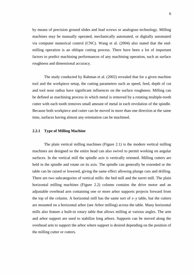
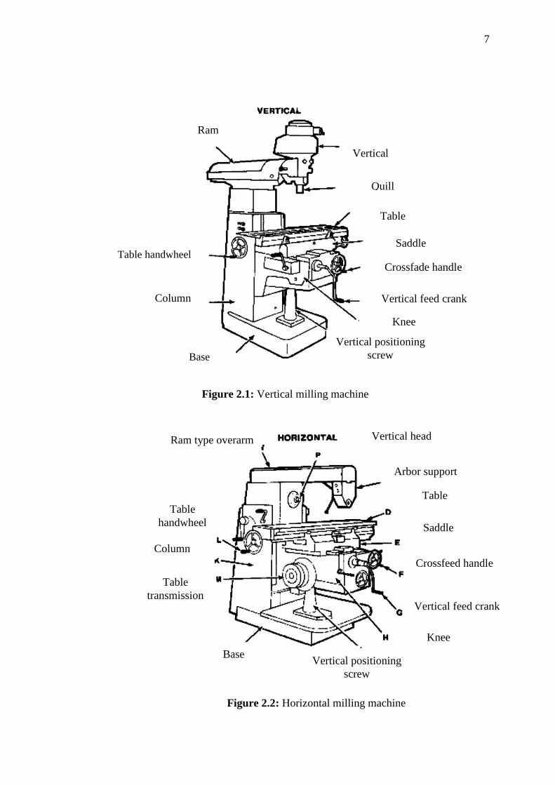
2.2.1 Type of Milling Machine
The plain vertical milling machines (Figure 2.1) is the modern vertical milling
machines are designed so the entire head can also swivel to permit working on angular
surfaces. In the vertical mill the spindle axis is vertically oriented. Milling cutters are
held in the spindle and rotate on its axis. The spindle can generally be extended or the
table can be raised or lowered, giving the same effect allowing plunge cuts and drilling.
There are two subcategories of vertical mills: the bed mill and the turret mill. The plain
horizontal milling machines (Figure 2.2) column contains the drive motor and an
adjustable overhead arm containing one or more arbor supports projects forward from
the top of the column. A horizontal mill has the same sort of x–y table, but the cutters
are mounted on a horizontal arbor (see Arbor milling) across the table. Many horizontal
mills also feature a built-in rotary table that allows milling at various angles. The arm
and arbor support are used to stabilize long arbors. Supports can be moved along the
overhead arm to support the arbor where support is desired depending on the position of
the milling cutter or cutters.
7
Figure 2.1: Vertical milling machine
Figure 2.2: Horizontal milling machine
Vertical head
Quill
Ram
Table
Saddle
Crossfade handle
Vertical feed crank
handle handle
Column
Knee
Table handwheel
Base
Vertical positioning
screw
Vertical head
Arbor support
Table
Saddle
Crossfeed handle
Vertical feed crank
Knee
Vertical positioning
screw
Base
Table
transmission
Column
Ram type overarm
Table
handwheel

8
2.2.2 End Milling Machine
The milling process can provide surface finishes and high tolerances and surface
finishes that is why it is deemed as the best way for adding precision features to a part
whose basic shape has been formed previously (Dotcheva and Millward, 2005). The
depth of the feature may be machined in a single pass or may be reached by machining
at a smaller axial depth of cut and making multiple passes. For a rough operation, the
recommended cutting speed and feed are selected for a peripheral or slot cut. A finish
operation will lower the cutting feed according to the finish requirements. Figure 2.3
shows an end milling process and the type of end mill used most abundantly is 2- flute
and 4-flute. According Dang et al. (2010), a lot of aerospace components such as dies
and moulds are commonly done by the machining processes of the flat end milling.
Figure 2.3: End milling process
9
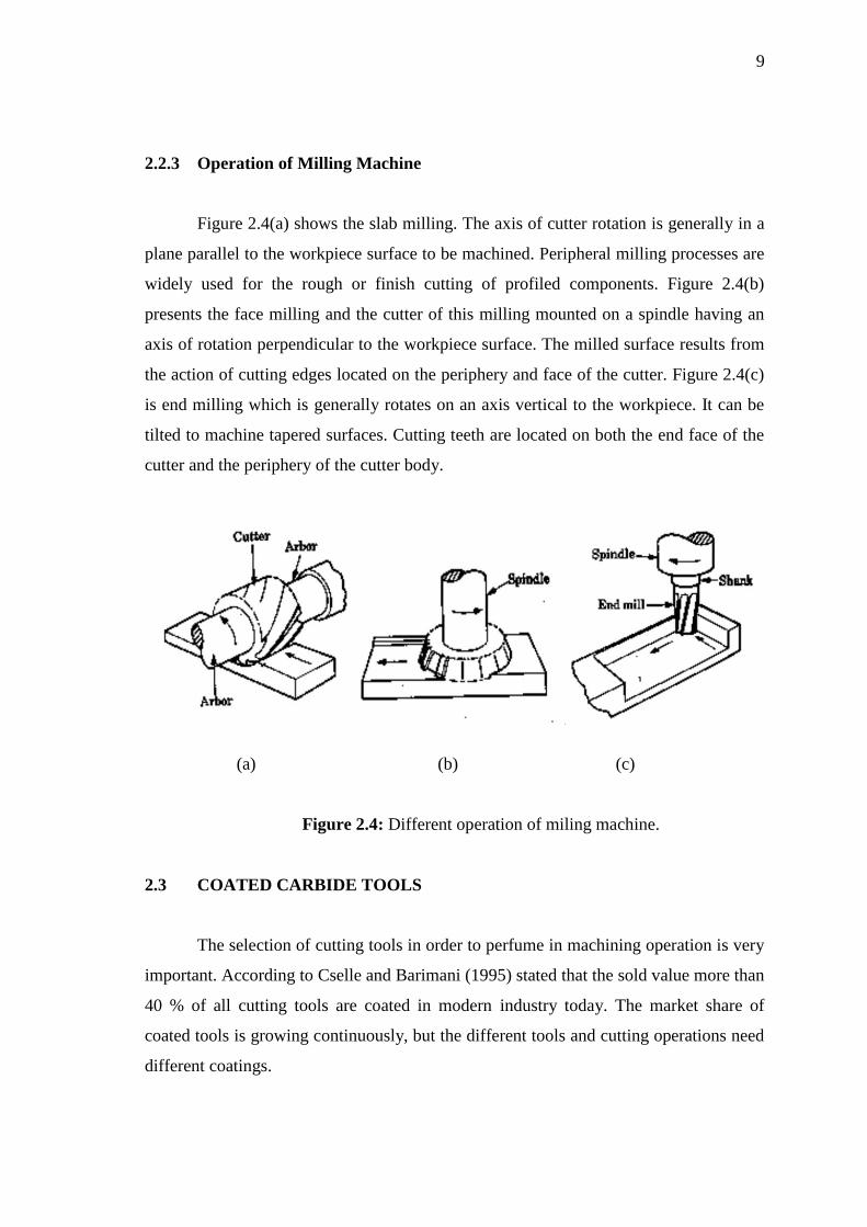
2.2.3 Operation of Milling Machine
Figure 2.4(a) shows the slab milling. The axis of cutter rotation is generally in a
plane parallel to the workpiece surface to be machined. Peripheral milling processes are
widely used for the rough or finish cutting of profiled components. Figure 2.4(b)
presents the face milling and the cutter of this milling mounted on a spindle having an
axis of rotation perpendicular to the workpiece surface. The milled surface results from
the action of cutting edges located on the periphery and face of the cutter. Figure 2.4(c)
is end milling which is generally rotates on an axis vertical to the workpiece. It can be
tilted to machine tapered surfaces. Cutting teeth are located on both the end face of the
cutter and the periphery of the cutter body.
(a) (b) (c)
Figure 2.4: Different operation of miling machine.
2.3 COATED CARBIDE TOOLS
The selection of cutting tools in order to perfume in machining operation is very
important. According to Cselle and Barimani (1995) stated that the sold value more than
40 % of all cutting tools are coated in modern industry today. The market share of
coated tools is growing continuously, but the different tools and cutting operations need
different coatings.

10
Coating have unique properties, such as higher adhesion, lower friction, higher
resistance to wear and cracking, higher hot hardness and impact resistance. Che-Haron
et al. (2007) stated during the process of machining with coated and uncoated carbide
tools failure results because of the stark flank wear and notching at the tool nose and the
depth of cut line. This improvement had a major impact on the economics of machining
operation in conjunction with continued improvement in the design and construction of
modern machine tools and their computer controls. As a result, coated tools nowadays
are used more than 40 % in industry and perform more than 80 % to all machining use
(Cselle and Barimani, 1995). Sahin and Motorcu (2005) explained the coated carbides
mare basically a cemented carbide insert material coated with one or more thin layers of
wear resistant material such as titanium carbide (TiC), Titanium nitride (TiN) and
aluminum oxide (Al2O3). The cutting tools coated carbide inserts have two techniques,
physical vapor deposition (PVD) and chemical vapor deposition (CVD). According to
Dudzinski et al. (2004), CTW 4615 is a coated carbide grade with TiAlN coating PVD
with grade designation P35 M50. Titanium-aluminium nitride (TiA1N) is used in the
cutting of material like difficult -to- machine material.
2.4 MINIMUM QUANTITY LUBRICATION
Minimum quantity lubrication is constructed on the principle that a drop of
liquid is split by an air flow, distributed in streaks and transported in the direction of
flow of air. The consumptions oil in industrial applications is in the range of
approximately 10-100 ml per hour (Kamata and Obikawa 2007). In machining,
conventional cutting fluid application fails to penetrate the chip-tool interface and thus
cannot remove heat effectively. According Klocke and Eisenblatter (1997) stated that
the overall performance of cutting operations MQL is very attractive as it consists of
cutting fluid volume reduction, by use of small amounts of fluid. The present work
experimentally investigates the role of MQL on surface roughness, tool flank wear in
end milling at different speed combinations by high speed super cobalt tool.
The minimum quantity lubrication represents the use of cutting fluid in smaller
quantity which is around ten-thousandth of the amount of cutting fluid used in flood-
cooled machining (Machado and Wallbank, 1997) and (Rahman et al., 2001). MQL

11
contains of a mixture of pressurized air and oil micro-droplets applied directly into the
interface between the tool and chips. However, the question of how the lubricants can
decrease the friction under very high temperature and loads is still not answered
especially for long engagements times. The MQL machining is nearly equal or often
better than the traditional wet machining in tool life and surface finish when cutting
steels and aluminum alloys (Kamata and Obikawa, 2007).
2.5 ALUMINUM ALLOY
Aluminum alloys are alloys in which aluminum is the predominant metal.
Characteristic alloying elements are copper, zinc, manganese, silicon, and magnesium.
Cselle (1995) mentioned that the majority of aluminum alloys can be machined at high-
speed practically without sacrificing tool life. In that case the dynamics of machine tool
and fixture set the upper limit for surface speed in cutting. About 85 % of aluminum is
used for wrought products, for example rolled plate, foils and extrusions. AA6061-T6 is
high strength Al–Mg–Si alloys that can increase the ductility and the toughness. The
aluminum alloys are widely used in engineering structures and mechanisms where light
weight or corrosion resistance is required (Robert and Richard, 1997). Many
organizations publish more specific standards for the manufacture of aluminum alloy,
including the Society of Automotive Engineers standards organization, specifically its
aerospace standards subgroups (Sreejith, 2008).
2.6 PROCESS PARAMETERS
The parameter dependS on the machining properties such as how maximum
spindle speed that the machining can conduct. According Kincl et al. (2005), the
procedure of choosing the optimum level of cutting tools, machines and cutting
parameters and condition is very long and costly. These experiments have the input and
output conduct by the DOE. The input are depth of cut, radial depth of cut, feed rate,
cutting speed and the flow rate of the MQL. The outputs for this experiment are surface
roughness tool wear and material removal rate.
12
2.6.1 Cutting Speed
Cutting speed is the speed at the outside edge of the milling cutter as it is
rotating. The hardness of the cutting tool has a great deal to with the recommended
cutting speed. Based on the observation by Ravi and Kumar (2011), the cutting speed
increased, the cutting temperature increases under all the machining conditions, which
may be attributed to an increase in the cutting energy dissipation rate. The cutting speed
must be set to the machine to ensure the cutting operation is correct and to avoid the
cutting tool and workpiece damage during the cutting operation. To set the cutting speed
we need to calculate the revolution per minute (RPM). The RPM calculation depends on
the cutting speed and the size of the cutter. The cutting speeds can be expressed as
Equation (2.1):
cutter ofDiameter
4speed Cutting
RPM (2.1)
The spindle speed suggested by Dhar et al. (2006) for the steel according to
milling machine is 110 m/min and it is a good finish surface roughness. The value of the
spindle speed is fix and the optimum value for these is 110 m/min. Amin et al. (2007)
carried out an experimental study and suggested that the spindle speed is 120 m/min to
250 m/min and it observed to cutting performance tools wear related to the uncoated
carbide in term of tool life. The final optimum value of this parameter is 120 m/min
related to the surface roughness and the tool wear according to the experiment. Ezugwu
et al. (2005) valuated the cutting performance of different CBN tool grades in finish
turning Ti–6Al–4V (IMI 318) alloy at high cutting conditions, up to 250 m/min, with
various coolant supplies. They investigated the tool wear, failure modes, cutting and
feed forces and surface roughness of machined and used to access the performance of
the cutting tools. The value of cutting speed given by Liao et al. (2007) is 150 m/min for
the minimum and 250 m/min for the maximum value. The general expectation shows
when the increasing of the cutting speed the cutting force will decrease. The optimum
value is the range of 200 m/min to 250 m/min for the best result of the surface finish.

13
The research carried out by Attanasio et al. (2006) to determine the technique
advantages to the tool wear reduction using the rake and flank tool decided to use the fix
value for the spindle speed which is 300 m/min. The optimum value is 300 m/min to
guarantee acquire the best condition for tool. Arumugam et al. (2006) investigated that
the cutting speed 480 to 690 m/min was selected in dry machining of aluminum-silicon
alloy experiment. Based on the experiment the optimum value is 690 m/min that make
the surface finish, feed and depth of cut in optimizing the mass concentration.
Ghani et al. (2004b) make an analysis according to the experiment performance
of P10 TiN coated carbide at high cutting steel by end milling with cutting speed 224
m/min to 355 m/min. In research study carried out by Yan et al. (2012), the influence of
MQL on surface roughness in milling and the cutting speed is 94.2 m/min to 219.8
m/min and the optimum value is obtained of 219.8 m/min. In another experiment by
using the liquid nitrogen in end milling, Ravi and Kumar (2011) used the cutting speed
range of 75 m/min to 250 m/min. 75 m/min is the optimum value that decided in which
to provide in low cutting temperature, tool wear, surface roughness and the cutting
force.
2.6.2 Feed Rate
Feet rate is refer to how fast the cutting tool moves through the workpiece. This
parameter unit is usually mm/rev. Liao et al. (2007) suggested that the value of the feed
rate is 0.10 mm/rev to 0.2 mm/rev according to the experiment of MQL in high milling
by coated carbide. The optimum feed rate of the experiment 0.15 mm/rev to achieve the
good surface finish. The MQL technique give advantages to tool wear (Attanasio et al.,
2006). The range of the feed rate is decided between 0.20 mm/rev and 0.26 mm/rev. In
the other hand, Arumugam et al. (2006) use the range feed rate between 0.2 mm/rev and
0.4 mm/rev in their investigated which is dry machining of aluminum–silicon alloy
coated cutting tools insert. The result showed the work piece average surface roughness,
the higher feed rate and depth of cut. Ghani et al. (2004b) investigated the performance
of P10 TiN coated carbide in milling recommended the range of the feed rate is between
0.1 mm/tooth and 0.25 mm/tooth. The feed rate value increase in higher cutting force