experimental investigation of reinforced ... beam with openings for combined bending and shear. the...
TRANSCRIPT

International Research Journal of Engineering and Technology (IRJET) e-ISSN: 2395 -0056
Volume: 04 Issue: 06 | June -2017 www.irjet.net p-ISSN: 2395-0072
© 2017, IRJET | Impact Factor value: 5.181 | ISO 9001:2008 Certified Journal | Page 824
EXPERIMENTAL INVESTIGATION OF REINFORCED CONCRETE BEAM WITH OPENING FOR COMBINED BENDING AND SHEAR
Rohit Vyas, Dr.Sanjay kulkarni, Nikhil Landge ---------------------------------------------------------------------***---------------------------------------------------------------------
Abstract - In the modern method of construction of building, pipes and ducts for services like water supply, sewage, air conditioning, electricity, telephone and computer networks are to be placed in appropriate positions. Usually, these pipes and ducts are connected and kept below the beam soffit and for aesthetic purpose these are covered by false ceiling thus introducing the dead space. This research aims at providing transverse openings in the beam so that the utility pipes and service ducts can be passed through the opening which may result in systematic accommodation of pipes and ducts and also provide economic savings in the construction of multi-storey buildings. This paper deals with the analysis and design of such beams under the loading case of bending and shear. Index Terms - ANSYS, voided beam, transverse openings, normal stresses, deflection, compressive strength.
1 Introduction
For modern construction, the provision of providing transverse openings in the reinforced concrete beam would be a facility to allow the passage of utility pipes and ducts through the structure. This type of design would provoke and promote the structural designers to lower the height of the structure and to make structure better in design and at economical cost. In case of small buildings the savings would not be significant, but in case of high rise building savings in a single storey multiplied by no. of stories would result in substantial savings in total height, length of electrical wires and ducts, air conditioner pipes, plumbing material, partition surfaces and load on foundation. Due to the abrupt change in the cross section of the beam and introduction of opening in the beam the normal beam behaviour would change to a complex one. The opening corners would subject to high stress which would lead to cracking of beams. Also reduction in the stiffness of the beam would lead to excessive deflection under the service load. Thus proper detailing with sufficient amount of special reinforcement is to be provided for such beams to avoid the adverse effects on the strength and serviceability of the beam. Presently no design criteria is been mentioned in any of the code which is used for design of concrete building structure.
2 METHODOLOGY
An experimental investigation is to be carried of reinforced concrete beam with openings for combined bending and shear. The specimens of reinforced concrete beam with and without openings are to be casted. Casting and testing is
been done at the TOM (testing of material) lab of Dhole Patil college of Engineering under the guidance of Mrs. Pranjali Kulkarni, HOD, civil department. The values of the peak load and maximum deflection are recorded. Similar specimens are also designed analytically in finite element tool ANSYS and the values of the maximum stress and deflection are obtained. According to these values the appropriate designing of the reinforcement is done in the beams and tested. Methods of analysis are:
A. Analytical approach using FEM tool ANSYS. B. Experimental testing of beams.
3 EXPERIMENATL WORK
3.1 COMPRESSIVE STRENGTH OF CONCRETE
Cubes of standard size 150x150x150mm size are casted and
tested practically for its crushing/compressive strength so as
to validate the strength of M25 grade concrete. In total 27
cubes are casted. 9 cubes are casted per day out of which
each set of 3 is tested on 3rd, 7th and 28th day respectively.
The average values of 3, 7, 28 days is calculated. Average
values of the strength obtained of all the cubes are shown in
table 1 followed by its graphical representation seen in Fig.1.
Fig.2 shows the casted cubes followed by its testing as
shown in Fig.3.
Table 1
Average values of the compressive strength of
cubes
3 days 19.32 N/mm2
7 days 22.34 N/mm2
28 days 37.22 N/mm2

International Research Journal of Engineering and Technology (IRJET) e-ISSN: 2395 -0056
Volume: 04 Issue: 06 | June -2017 www.irjet.net p-ISSN: 2395-0072
© 2017, IRJET | Impact Factor value: 5.181 | ISO 9001:2008 Certified Journal | Page 825
Fig.1 Chart showing the increase in strength with
the time of curing.
Fig.2 Casting of cubes.
Fig. 3 Testing of Cubes.
3.2 Scaling and casting of beams A standard RCC beam of size 230mm x 450mm having length
2.5m is been considered from a residential plan and
designed using IS 456. Two different openings sizes of
100mm and 150mm are taken into consideration at different
locations along the length of the beam. Fe415 steel and M25
concrete are used. As casting curing and transporting of such
beams is difficult, it is scaled down to a size which is easy for
practical purpose. Beam is scaled down to a size of 65mm
x126mm and having length 700mm. Similarly openings are
scaled down to a size of 28mm and 42mm respectively.
Initially 3 beams are casted and tested on the UTM
without any reinforcement in it having one, two, three
openings respectively on each beam of size 28mm so as to
identify the cracking pattern due to which the beam fails. Fig.
4 shows the formwork of the beams and placing of PVC pipes
so as to form the required openings. Fig. 5 shows the casting
and testing of the beam with 3 openings. The cracking
pattern of the beam can be seen in this figure.
Fig. 4 Formwork prepared on site.
Fig. 5 Casting and testing of beam with three opening.

International Research Journal of Engineering and Technology (IRJET) e-ISSN: 2395 -0056
Volume: 04 Issue: 06 | June -2017 www.irjet.net p-ISSN: 2395-0072
© 2017, IRJET | Impact Factor value: 5.181 | ISO 9001:2008 Certified Journal | Page 826
3.3 Loading condition
The beam is placed over the jaws of the UTM and fixed over
it. The centre of the beam is marked and on equal distance
from the centre rolled steel sections are placed on each side.
Over these rolled steel sections a mild steel plate is placed
over which the central point load is applied by the UTM. This
procedure is followed so as to apply a two point load as per
IS specification of applying a point load. Fig. 6 shows a
typical arrangement of the loading condition made.
Fig.6 Typical arrangement of two point loading condition.
4 Analytical approach
The beams will be modelled in the Finite Element Method
tool ANSYS and loading will be provided as shown above in
the two point form. The results will be noted and compared
to the experimental results. So as to take the worst cases into
consideration the openings are kept at the centre of the
beam where the bending moment is maximum and at a
distance from support where the shear force is maximum.
List of models to be prepared are:
• Solid beam without hole.
• Beam with 100mm circular hole at L/2 distance.
• Beam with 150mm circular hole at L/2 distance.
• Beam with two 100mm circular holes at 175mm
from both ends.
• Beam with two 150mm circular holes at 175mm
from both ends.
• Beam with three 100mm circular holes at L/2
distance and other two at 175mm from both ends.
• Beam with three 150mm circular holes at L/2
distance and other two at 175mm from both ends.
5 Results
Sample models been prepared in ANSYS with one, two, three
openings along with the values of maximum deflection and
stresses are as shown below:
Model of the beam without any opening
Results: Maximum Deflection: 0.00052314m
Maximum Stress: 3.7952e7 Pa
Maximum Strain: 0.00013948
Model of beam having a single opening of size
100mm
Results: Maximum Deflection: 0.00051432m
Maximum Stress: 3.289e7 Pa
Maximum Strain: 0.00014326
Model of beam having two opening of size 100mm
International Research Journal of Engineering and Technology (IRJET) e-ISSN: 2395 -0056
Volume: 04 Issue: 06 | June -2017 www.irjet.net p-ISSN: 2395-0072
© 2017, IRJET | Impact Factor value: 5.181 | ISO 9001:2008 Certified Journal | Page 827
Results: Maximum Deflection: 0.00053687m
Maximum Stress: 2.9977e7 Pa
Maximum Strain: 0.00019766
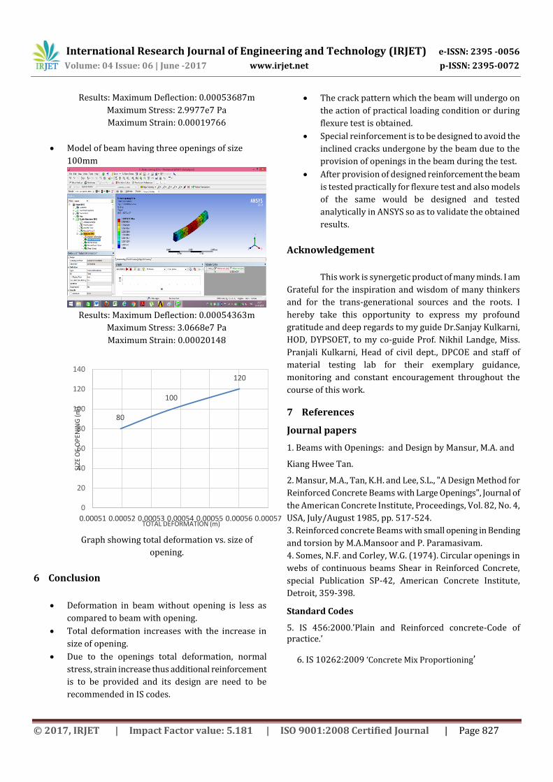
Model of beam having three openings of size
100mm
Results: Maximum Deflection: 0.00054363m
Maximum Stress: 3.0668e7 Pa
Maximum Strain: 0.00020148
80
100
120
0
20
40
60
80
100
120
140
0.00051 0.00052 0.00053 0.00054 0.00055 0.00056 0.00057
SIZE
OF
OP
ENIN
G (
m)
TOTAL DEFORMATION (m)
Graph showing total deformation vs. size of
opening.
6 Conclusion
Deformation in beam without opening is less as
compared to beam with opening.
Total deformation increases with the increase in
size of opening.
Due to the openings total deformation, normal
stress, strain increase thus additional reinforcement
is to be provided and its design are need to be
recommended in IS codes.
The crack pattern which the beam will undergo on
the action of practical loading condition or during
flexure test is obtained.
Special reinforcement is to be designed to avoid the
inclined cracks undergone by the beam due to the
provision of openings in the beam during the test.
After provision of designed reinforcement the beam
is tested practically for flexure test and also models
of the same would be designed and tested
analytically in ANSYS so as to validate the obtained
results.
Acknowledgement
This work is synergetic product of many minds. I am
Grateful for the inspiration and wisdom of many thinkers
and for the trans-generational sources and the roots. I
hereby take this opportunity to express my profound
gratitude and deep regards to my guide Dr.Sanjay Kulkarni,
HOD, DYPSOET, to my co-guide Prof. Nikhil Landge, Miss.
Pranjali Kulkarni, Head of civil dept., DPCOE and staff of
material testing lab for their exemplary guidance,
monitoring and constant encouragement throughout the
course of this work.
7 References
Journal papers
1. Beams with Openings: and Design by Mansur, M.A. and
Kiang Hwee Tan.
2. Mansur, M.A., Tan, K.H. and Lee, S.L., "A Design Method for
Reinforced Concrete Beams with Large Openings", Journal of
the American Concrete Institute, Proceedings, Vol. 82, No. 4,
USA, July/August 1985, pp. 517-524.
3. Reinforced concrete Beams with small opening in Bending
and torsion by M.A.Mansoor and P. Paramasivam.
4. Somes, N.F. and Corley, W.G. (1974). Circular openings in
webs of continuous beams Shear in Reinforced Concrete,
special Publication SP-42, American Concrete Institute,
Detroit, 359-398.
Standard Codes
5. IS 456:2000.’Plain and Reinforced concrete-Code of practice.’
6. IS 10262:2009 ‘Concrete Mix Proportioning’