experimental behavior of concrete-filled steel tubular...
TRANSCRIPT

Research ArticleExperimental Behavior of Concrete-Filled Steel TubularMembersSubjected to Lateral Loads
Chengzhi Wang Xin Liu and Pengfei Li
Chongqing Jiaotong University Chongqing 400074 China
Correspondence should be addressed to Chengzhi Wang wangczcqjtueducn
Received 28 November 2017 Revised 21 March 2018 Accepted 31 March 2018 Published 8 May 2018
Academic Editor Enzo Martinelli
Copyright copy 2018 Chengzhi Wang et al is is an open access article distributed under the Creative Commons AttributionLicense which permits unrestricted use distribution and reproduction in any medium provided the original work isproperly cited
e findings of an experimental study that was undertaken to investigate the performance of concrete-filled steel tubular memberssubjected to lateral loads are reported in this study Columns of pure concrete concrete with reinforcing bars and two steel tubethicknesses were considered Two different tests were conducted in this study One test is used to research the performance of steeltube-reinforced concrete model piles under a lateral loading e other test is used to research the effect of the depth of rockembedment for piles embedded in a foundation to simulate actual engineering applications in an experimental study Accordingto these test results a detailed analysis was carried out on the relationships such as the stress-strain and load-displacementrelationships for the specimen ese tests show that the steel tube thickness and steel bars will significantly enhance the lateralbearing capacity and rigidity of the composite components Additionally the ultimate bending moment formula of a steel tube-reinforced concrete pile is deducede comparison of the calculated results with the experimental results shows that this formulais applicable for this type of pile foundation
1 Introduction
Concrete-filled steel tube (CFST) members are well recog-nized for their excellent performance owing to the combi-nation of the merits of steel and concrete materialserefore CFSTs are increasingly used in many structuralapplications including columns supporting platforms ofoffshore structures roofs of storage tanks bridge piers pilesand columns in seismic zones [1]
In 1957 since Kloppel and Goder et al [2] reported theirstudy of concrete-filled steel tubes scholars from variouscountries have conducted extensive and in-depth experi-mental studies of these structures In 1967 Furlong [3]reported the results of axial and compressive bearing tests of52 CFSTs In 1993 Grauers [4] carried out an experimentalstudy on high-strength concrete-filled steel tubes in theexperiments the core of the concrete strength was found tobe up to 103MPa In 2001 Elchalakani et al [5] presented anexperimental investigation of the flexural behavior of cir-cular CFT subjected to large deformation pure bendingwhere dt 12 to 110 and compared the behavior of empty
and void-filled cold-formed circular hollow sections underpure plastic bending In 2002 Zhao and Grezebieta [6]conducted axial and pure bending tests on interlayerconcrete-filled steel tubes Aval et al [7] considered theproblem of the bond slip and the combination of steel tubeand concrete and they used the fiber model method toanalyze the load-deformation curve of the bending memberunder a cyclic load More recently Montuori and Piluso [8]reported the ultimate behavior of concrete-filled tubular(CFT) members subjected to nonuniform bending momentFurthermore a fiber model able to predict the ultimateresponse of CFTmembers was also presented and comparedwith the experimental results and the comparison betweenexperimental and numerical results shows a good agreementpointing out the accuracy of the proposed fiber model
In the past there has been extensive research on thebehavior of CFST members subjected to axial compression[9ndash12] axial tension [13ndash16] and more complex loadingconditions [17ndash22] Compared with the previously conductedresearch in the above fields relatively little work has beenreported on the lateral loading behavior of CFST members
HindawiAdvances in Materials Science and EngineeringVolume 2018 Article ID 9065378 15 pageshttpsdoiorg10115520189065378
e above literature review indicates that research on thelateral loading behavior of CFST members is still limitedespecially for CFST members that have been widely used inengineering practices such as high-pile terminal structures andpile foundations ese applications utilize CFSTmembers tonot only bear the pile cap beam and other vertical loads butalso bear a ship impact force and support other concentrationsof the load Under the action of horizontal loads the pilefoundation of a high-pile wharf has been used when the pile isbroken In this paper in order to compare the influence of thethickness of a steel tube on the bearing capacity of compositemembers a detailed experimental study on circular CFSTs hasbeen undertaken under lateral loads e bearing capacity ofdifferent types of concrete-filled steel tubular structures isdiscussed Additionally the influence of actual engineeringapplications on the depth of concrete-filled steel tubes wasstudied and analyzed
2 Experimental Study
21 Material Properties e steel tubes used for the con-struction of the CFST specimens were cold-rolled steel tubesYoungrsquos modulus of the tube (E) is 200GPa and the yieldstrength of the tube (fy) is 335MPa All the test specimens arescaled components e specimens consist of the main bar andthe stirrup and the yield strength of the steel bars is 335MPae core concretematerial of the CFSTismade of high-strengthM30 cement mortar this grout has the same elastic moduli asthe actual pile According to the code JGJT 98-2010 [23] thetest mix design of all the specimens is shown in Table 1
22 Specimens without Foundation Tests
221 Test Specimen Design e specimens without foun-dation tests were used to study the behavior under a lateral load
Column specimens with a length of 1200mmwere designed asshown in Figure 1e columns were reinforced with the mainbar and the stirrup Additionally themain bar has a diameter of6mm and the stirrup has a diameter of 12mm e stirrupspacing is 50 cm in the columne distance between the outerstirrup and the steel casing is 20mm
As summarized in Table 2 there were four specimense outer diameters of the tubes (D) were 165mm esection type of specimens NC1 NC2 and NC4 is thereinforced concrete section and the section type of specimenNC3 is the concrete section In addition except for thespecimen NC4 all other specimens have steel casing Andthe thicknesses of the steel casing were 0mm 12mm and16mm respectively
222 Test Setup and Instrumentation e test setup andinstrumentation for the specimens are presented schemat-ically in Figure 2 One servohydraulic actuator with a loadingcapacity of 500 kN was used in the loading frame whichallows lateral forces to be applied to the dowel bar
e experiment uses graded loading and the specificloadingmethod is as followse load is divided into 8 stagesaccording to the estimated ultimate carrying capacity butthe load grading is not consistent during the initial stageeach of the first few increments of loading was approxi-mately 10 of the predicted failure load but the loading isgradually reduced after the plastic stage of deformation isreached
As shown in Figure 2 the deformation is measured byusing dial indicators at the lower center and both ends of thespecimen e measuring range of the instrument is 0 to50mm and the maximummeasurement accuracy is 001mme instrument can measure the absolute displacement andthe relative displacement of the middle of the pile
Table 1 Concrete mix design
Strengthgrade
Water to cementratio (mass ratio)
Water-reducingagent (kgm3)
Cement(kgm3)
Water(kgm3)
Gravel(kgm3)
Sand(kgm3)
C30 065 0 300 195 1220 685
φ = 12 mmφ = 6 mm D times t = 165 mm times 16 mm
φ = 12 mm
Inner stirrups
Outer stirrups
Steel casing
C=
20 m
m
D=
165
mm
L=
1200
mm
Steel casing
Figure 1 Specimen size
2 Advances in Materials Science and Engineering
For this test the strain gauges were attached to the pileside to measure the variation in the strain with the load edistance between the rst strain gauge and the column topand the distance between the bottom strain gauge and thepile bottom were both 30 cm and the distance between theadjacent strain gauge layers was 30 cm Each strain gaugemeasured the axial and lateral data e experimental deviceschematic and strain gauge point position map are shown inFigure 3
23 Specimens with Foundation Tests
231 Test Specimen Design To further study the perfor-mance of CFSTs under lateral loading additional tests were
performed ese tests simulate the actual engineering con-ditions and the specimen is embedded in a foundation
A total of six columns were tested in this study includingthree specimens with steel casing and three specimens withoutsteel casing e specimen size is shown in Figure 4 ecolumns consist of the main bar and the stirrup In additionthe main bar has a diameter of 6mm and the stirrup hasa diameter of 1mme stirrup spacing is 3 cm in the column
Table 3 provides details of the column specimens BC1 toBC6 All the specimens were placed vertically into thefoundatione length of all the specimens was 800mm andthe thicknesses of the steel casing were 1mm e outerdiameters of the tubes (D) were 100mm and the distancebetween the stirrup and the steel casing is 5mme various
Table 2 Details of the specimens
Specimen number D (mm) t (mm) L (mm) Section type Steel casing fcu (MPa) fy (MPa)NC1 165 12 1200 Concrete section Y 3020 335NC2 165 16 1200 Composite section Y 3020 335NC3 165 12 1200 Composite section Y 3020 335NC4 165 00 1200 Composite section N 3020 335NoteD sectional diameter of the circular steel tube t wall thickness of the steel tube L length of the specimens composite section reinforced concrete crosssection concrete section concrete cross section fcu concrete cube compressive strength fy yield strength of steel
Dial indicator
Reaction frame
Load cell
Servohydraulic actuators
Steel casing
L = 1200 mm
D=
165
mm
(a) (b)
Figure 2 Test setup and instrumentation of specimens (a) General view (b) Photograph of loading device
Specimen
600 mm
Loading point
600 mm
Measuring point 6
Measuring point 3Measuring point 5Measuring point 4 165
mm
Measuring point 2
Bearing
1200 mm
300 mm
Measuring point 1
825
mm
150 mm
Figure 3 Point position map
Advances in Materials Science and Engineering 3
parameters considered in this investigation were the rock-socketed depth and the steel casing
e rock-socketed portion of the specimen was placed inthe simulated foundation e model foundation size is24mtimes 13mtimes 1m and the concrete strength is low tosimulate strong weathering mudstones e concrete mixratio is 125 cementitious material 125 gravel and 50sand In addition the loading device is a separate servo-hydraulic actuator with a loading capacity of 100 kN and itwas placed on the top and the top of the servohydraulicactuator was fixed on the reverse beam A schematic diagramof the device setup is shown in Figure 5
232 Test Setup and Instrumentation In the test theloading of the pile top is measured by the load sensor edisplacement of the pile top and the lateral displacement atthe rock surface are measured by a displacement transducere strain gauge is used to measure the axial strain and thelateral strain of the concrete pile e strain gauges areshown in Figure 6 During step-by-step loading to keep eachload the same the load is calculated according to 10 of theestimated carrying capacitye first stage load is 2 times thegrading load the unloading is reduced by a consistent 20 ofthe carrying capacity e requirements are that the trans-mission load is uniform continuous and stable and that thetime of loading is at least 1min
3 Results and Discussion
is section presents the main experimental results of thetested CFST members including the midspan load-deflection component strain-load and lateral load (P)versus lateral displacement curves Analyses of the in-fluence of the steel casing on the ultimate load-carryingcapacity and the mechanisms driving these relationshipsare also performed e influence of different test pa-rameters on the behavior of the CFST members is alsodiscussed
31 Specimens without Foundation Tests
311 Midspan Load-Deflection Curve e measured mid-span deflection varies with the load of the regular curve asshown in Figure 7
From the load-deflection curve of Figure 7 the ultimatebearing capacities of the specimens with a steel guard aresignificantly improved from specimens NC4 to NC2 andNC4 to NC3 According to the measured results the ulti-mate bearing capacity of ordinary reinforced concrete pilesis 30 kN however for the components with a steel tubethickness of 12mm the ultimate bearing capacity is ap-proximately 120 kN and for the specimen with a steeltube thickness of 16mm the ultimate load capacity is
φ = 1 mm
D=
100
mm
500
mm
300
mm
Foundation
φ = 4 mm D times t = 100 mm times 1 mm
Stirrups
Steel casing
C=
5 m
mFigure 4 Specimen size
Table 3 Details of the specimens
Specimen number D (mm) t (mm) L (mm) Rock-socketed depth (mm) Steel casing fcu (MPa) fy (MPa)BC1 100 1 800 300 Y 3132 235BC2 100 1 800 300 N 3132 235BC3 100 1 800 400 Y 3132 235BC4 100 1 800 400 N 3132 235BC5 100 1 800 500 Y 3132 235BC6 100 1 800 500 N 3132 235Note D sectional diameter of the circular steel tube t wall thickness of the steel tube L length of the specimens fcu concrete cube compressive strengthfy yield strength of steel
4 Advances in Materials Science and Engineering
approximately 145 kN which is 3-4 times bearing capacity ofthe reinforced concrete component e greater the thick-ness of the steel tube the higher the ultimate carryingcapacity
As shown in Figure 7 for the reinforced concrete mem-bers because of their smaller spans during the entire loadingprocess the midspan deection increases linearly with theincrease or decrease in the load and there is no elastic-plasticphase In addition with the addition of steel-retaining ele-ments during the loading process as the load increases themidspan deection presented three working stages the elasticphase is exhibited before the load reaches 70 kN With a linearincrease in the load the midspan deection then enters theelastoplastic stage Before the load increases to 110 kN the
components exhibit elastoplasticity as the load continues toincrease the plastic phase is observed until the component isfailure
312 Strain-Load Curve e variation in the strain of thereinforced concrete pile foundation model with the load isshown in Figure 8 here only longitudinal observations aremade for the pile foundation
From Figure 8(a) we can see that the transverse strain ofthe reinforced concrete in the center of the pile is considerablygreater than the strain at both ends For a more intuitive
e model pile
Bedrock surface
Pile strain gauge
Foundation strain gauge
200
mm
200
mm
50 m
m
300
mm
50 m
mtimes8
50 m
m
500
mm
Figure 6 Test strain gauge layout diagram
160
120
80
40
00
Load
(kN
)
54321Deflection (mm)
NC2NC3NC4
Figure 7 Specimen load-deection curve
Dial indicator Servohydraulic
Reaction frame
Load cell
Foundation
Specimen
1000
mm
actuators
1300 mm
(a) (b)
Figure 5 Test setup and instrumentation of specimens
Advances in Materials Science and Engineering 5
expression of the end strain themeasured strain at point 1 point3 point 4 and point 6 are shown in Figure 8(b) Figure 8(a)shows that when the load increases to approximately 10 kNthe axial strain increases rapidly and the concrete in thetension zone is cracked and rapidly propagates toward theneutral surface e reinforced concrete members exhibit
brittle failure under a concentrated load as shown in Figure 9It can be seen from Figure 8(b) that in the pile bottom atpoint 1 and point 3 the ring strain has a large gap before thestate is in a state of tension After the cracks form the strainvalue quickly becomes a pressure strain because the midspancracks form rapidly increasing the midspan deflection and
30
25
20
15
10
5
0ndash5000 0 5000 10000 15000 20000
Load
(kN
)
Strain (με)
Measuring point 1 longitudinalMeasuring point 2 longitudinalMeasuring point 3 longitudinal
Measuring point 4 longitudinalMeasuring point 5 longitudinalMeasuring point 6 longitudinal
Specimen
Bearing
Measuring point 4 Measuring point 5 Measuring point 3
Measuring point 2Measuring point 1
Measuring point 6
Loading point
(a)
20
15
30
25
10
5
ndash80 ndash60 ndash40 ndash20 0 20 400
Load
(kN
)
Strain (με)
Specimen
Bearing
Measuring point 4 Measuring point 5 Measuring point 3
Measuring point 2Measuring point 1
Measuring point 6
Loading point
Measuring point 1 longitudinalMeasuring point 3 longitudinalMeasuring point 4 longitudinalMeasuring point 6 longitudinal
(b)
FIGURE 8 Strain-load curves for specimen NC4 (a) all the measuring points and (b) several of the measuring points
6 Advances in Materials Science and Engineering
the concrete longitudinal fiber appears to be under a greatertensile strain At this point the measuring point 1 and themeasuring point 3 of the concrete fiber are still in the elasticphase so the tensile ring strain quickly decreases to 0 Inaddition as the load increases a pressure strain develops Inaddition at the side end of measuring point 4 and measuringpoint 6 before reaching the applied load of 10 kN thestrain value is approximately 0 that is before reaching thedamaging load the tensile zone of the pile has not yet beenextended to its neutral surface After the load reaches 10 kNthe strains at measuring point 4 and measuring point 6 beginto develop into compressive strains According to the analysisthe main reason for this change is the same as the above-mentioned change at points 1 and 3
emeasured strain of the steel tube-reinforced concretepiles in a foundation during the change in loading is shownin Figures 10 and 11 For the specimen NC3 the strain gaugeat point 6 was damaged and failed
It can be seen from Figures 10 and 11 that lateral bendingof steel casing-reinforced concrete pile foundation showsa marked ductility compared to the deformation of rein-forced concrete pile foundations e midspan tension zone(longitudinal measuring point 2) does not show a suddenincrease in strain in Figure 8 but is characterized by firstelasticity and then elastoplasticity erefore the use of steeltube protection has a very important role in the ductility ofthe pile foundation under enhanced lateral bending At thesame time in addition to the cross-measuring point 2 theother sides of the steel tube have longitudinal and cir-cumferential strains that change linearly with the load andthe ratio of the longitudinal strain and circumferential strainis approximately Poissonrsquos ratio of the steel casing ere-fore during the entire loading process in addition tomeasuring point 2 the rest of the measuring point along thesteel tubes are in the elastic phase is phenomenon showsthat using a steel tube greatly enhances the integrity of thepile Unlike under axial compression the effect of the steeltube on the core concrete is always present when a load isappliedrough the longitudinal and circumferential straincurves we can see that in the ring the steel tube anchorstrain is small that is the ring deformation is small eanalysis shows that this is the result of the interaction be-tween the steel tube itself and the concrete On one hand thelongitudinal stretching of the steel tube under tension causes
the ring to shrink so that the steel tube in the ring producespressure strain On the other hand the lateral deformationof the embedded concrete in the tension zone causes the steeltube to produce a tensile strain offsetting the circumfer-ential strain in the steel tube In addition within a certainthickness when the load is small (less than 70 of its lateralbending limit load) the effect of the steel casing thickness onthe bearing capacity of reinforced pile is not apparent butfor the ultimate deformation of the pile foundation the steelcasing thickness plays a certain role increasing the thicknessof the steel tube can effectively enhance the ductility of thepile foundation
According to the above analysis in the elastic phase dueto the limitations of the embedded concrete the steel tubedeformation occurs in the tensile zone under a triaxial forcestate At this point the concrete bears a small tensile stressand its main role is to limit the ring deformation of the steeltube In the elastoplastic stage with the increase in thedeformation of the steel tube the tube stress exceeds itsproportional limit and extends from the midsection to bothends At this later stage the maximum tensile fiber of the steeltube is yielding and developing internally After the steel tubeyields the strain increases rapidly due to the greater longi-tudinal deformation the concrete in the tension zone cracksWith the increase in the load the concrete cracks quicklypropagate damaging the component
313 Lateral Load (P) versus Lateral Displacement (Δ)Curves e lateral load (P) versus lateral displacement (Δ)curves for common specimens are presented in Figure 12e load-displacement curve of the NC3 specimen is shownin Figure 12(c)
It can be seen from the figures that the load-displacement curve exhibits a typical elastoplastic trendand the elastic-plastic demarcation point occurs at a load of100 kN In the elastic phase the deformation of the specimenis similar to the development with a linear load-displacement relationship When the load is increasedpast the cutoff point the load-displacement curve enters thenonlinear phase and the stiffness of the specimen decreasesgradually e change in the midspan displacement isaccelerated until the specimen is destroyed When the lateralload exceeds 100 kN the steel cylinder of the upper part ofthe specimen buckles and deforms the bending displace-ment is accelerated and the load-displacement curve un-dergoes a nonlinear stage When the specimen bearingcapacity decreases as the loading continues the steel casingwill undergo brittle fracture as shown in Figure 13
eNC1 NC2 NC3 and NC4 load-displacement curvesare shown in Figure 12 It can be seen by comparing theresults that with the increase in the thickness of the steeltube the transverse bearing stiffness and ultimate lateralbearing capacity of the specimen will increase e restrainteffect of the reinforced concrete on the core concrete willalso improve the rigidity and ultimate bearing capacity of thespecimenWhen the specimen has no steel tube restraint thestiffness ultimate bearing capacity and ultimate de-formation of the NC4 specimen are significantly smaller
Figure 9 Brittle failure of reinforced concrete
Advances in Materials Science and Engineering 7
140
120
100
80
60
40
20
0ndash400 ndash200 0 200 400 600 800 1000
Load
(kN
)
Strain (με)
Measuring point 1ring directionMeasuring point 2ring directionMeasuring point 3ring direction
Measuring point 4ring directionMeasuring point 5ring direction
Specimen
Bearing
Measuring point 4 Measuring point 5 Measuring point 3
Measuring point 2Measuring point 1
Measuring point 6
Loading point
(a)
100
120
140
80
60
40
20
0ndash2000 0 6000 80002000 4000
Load
(kN
)
Strain (με)
Measuring point 1 longitudinalMeasuring point 2 longitudinalMeasuring point 3 longitudinal
Measuring point 4 longitudinalMeasuring point 5 longitudinal
Specimen
Bearing
Measuring point 4 Measuring point 5 Measuring point 3
Measuring point 2Measuring point 1
Measuring point 6
Loading point
(b)
Figure 10 (a b) Strain-load curves for each measuring point of specimen NC3
8 Advances in Materials Science and Engineering
ndash400 ndash200 0 200 400 600 800 1000Strain (με)
Measuring point 1ring directionMeasuring point 2ring directionMeasuring point 3ring direction
Measuring point 4ring directionMeasuring point 6ring direction
160
140
120
100
80
60
40
20
0
Load
(kN
)Specimen
Bearing
Measuring point 4 Measuring point 5 Measuring point 3
Measuring point 2Measuring point 1
Measuring point 6
Loading point
(a)
ndash2000 0 6000 8000 1000 120002000 4000Strain (με)
Measuring point 1 longitudinalMeasuring point 2 longitudinalMeasuring point 3 longitudinal
Measuring point 4 longitudinalMeasuring point 5 longitudinalMeasuring point 6 longitudinal
100
120
140
160
80
60
40
20
0
Load
(kN
)
Specimen
Bearing
Measuring point 4 Measuring point 5 Measuring point 3
Measuring point 2Measuring point 1
Measuring point 6
Loading point
(b)
Figure 11 (a b) Strain-load curves for each measuring point of specimen NC2
Advances in Materials Science and Engineering 9
than the remaining three specimens erefore when thesteel-reinforced concrete composite components are used inpractical engineering applications the transverse bearingperformance and deformation performance are obviouslyimproved compared with those of the reinforced concrete
and concrete-lled steel tubular members e results of thetests of the four common specimens are summarized inTable 4
32 Specimens with Foundation Tests
321 Failure Modes After loading is complete the exca-vation of the foundation is recorded for the failure of themodel piles e photographs show that the failure modes ofthe steel-embedded rock-socketed piles and common rock-socketed piles are considerably dierent under lateral loadsFigure 14 shows the failure mode of the two rock-socketedpiles comparison chart for an ordinary rock-socketed pilethe damage surface is tilted and the tilt angle is approxi-mately 45deg For rock-socketed piles with steel cages thefailure surface is horizontal and along the bottom of the tubeFor these two kinds of piles the location of the failure surfaceis not the same the destruction surface of the common rock-socketed piles occurs across the surface of the foundation
NC1
0
0 1
Late
ral l
oad
(kN
)
Displacement (mm)2 3 4 5 6 7 8
20
40
60
80
100
120
140
(a)
NC2
0
25
50
75
100
125
150
175
200
0 1Displacement (mm)
2 3 4 5 6 7
Late
ral l
oad
(kN
)
(b)
NC3
0
20
40
60
80
100
120
140
160
180
0 1Displacement (mm)2 3 4 5 6
Late
ral l
oad
(kN
)
(c)
NC4
0
20
40
60
80
100
0 1Displacement (mm)2 3 4 5 6
Late
ral l
oad
(kN
)
(d)
Figure 12 andashd) Lateral load (P) versus lateral displacement (Δ) curves
Figure 13 Brittle fracture of the steel casing of specimen NC3
10 Advances in Materials Science and Engineering
and the damage surface of the steel tube rock-socketed pile isburied under the surface of the foundation
322 Load-Deection Curve Horizontal loads were appliedto the six model piles the lateral deformation of the pile topwas measured by the horizontal displacement gauge at thetop of the pile to better analyze the eect of steel casing onthe bearing capacity of rock-socketed piles e six groups ofload-deection curves each representing a dierent rock-embedment depth are drawn in Figures 15(a)ndash15(c)
From Figures 15(a)ndash15(c) it can be seen that the in-uence of the steel casing on the horizontal bearing capacityof the rock-socketed piles is basically the same It can be seenfrom Figure 15 that the load-deection curves of the tworock-socketed piles are generally nonlinear but are linearunder small loads For the model pile BC1 when the hor-izontal displacement is less than 3mm the horizontal dis-placement of the pile top increases linearly with the lateralload When the horizontal displacement exceeds 3mm the
load of the pile has a small uctuation when the horizontaldisplacement of the pile is approximately 9mm the hori-zontal load reaches maximum which is the horizontal limitload capacity of the pile For pile BC2 when the horizontaldisplacement is less than 6mm the horizontal displacementof the pile top increases linearly with the lateral load Whenthe horizontal displacement exceeds 6mm it changesnonlinearly with the load When the horizontal displace-ment of the pile top is approximately 15mm the ultimateload capacity is achieved e horizontal ultimate load-carrying capacity of rock-socketed piles is approximately04 kN while that of conventional rock-socketed piles isapproximately 165 kN indicating that the ultimate bearingcapacity of rock-socketed piles is only 14 of the commonrock-socketed pile In addition the inuence of the steelcasing on the rock-socketed piles is basically the same bothkinds of steel-retaining cylinders will greatly reduce thehorizontal bearing capacity of the pile body but slightlyincrease the deformation modulus
Figure 16 shows the load-deection curves of the rock-socketed piles with dierent rock-embedment depths
It can be seen from Figure 16 that these three curves arelinear at low loads and that the slope increases with the depthof embedment in the rock formation indicating that theincrease in the rock depth will increase the horizontal de-formation modulus of the pile e bearing capacity isapproximately 045 kN when the depth of the rock em-bedment is 300mm the carrying capacity is approximately070 kN at 400mm and the carrying capacity of 500mm isreduced to 04 kN showing that increasing the depth of therock embedment does not always improve the carryingcapacity
323 Bearing Capacity e bearing capacity of rock-socketed piles is aected by many factors It can be seenfrom the horizontal load-deection curves of the pile topswith dierent rock-embedded depths that the depth of rockembedment has a considerable inuence on the bearingcapacity of rock-socketed piles in common rock-socketedpiles and those with steel cages e slope of the load-deection curve shows the stiness of the pile against lat-eral deformation this relationship can be expressed by thefollowing equation
W Fλ (1)
where W is the stiness F represents the horizontal loadapplied by the pile top and λ is the horizontal displacement
Table 4 Test results of common specimens
Specimen number D (mm) t (mm) L (mm) Section type Steel casing Fu (kN) Fud (mm)NC1 165 12 1200 Concrete section Y 13000 71NC2 165 16 1200 Composite section Y 17700 64NC3 165 12 1200 Composite section Y 16000 58NC4 165 00 1200 Composite section N 8500 56NoteD sectional diameter of the circular steel tube t wall thickness of the steel tube L length of the specimens composite section reinforced concrete crosssection concrete section concrete cross section Fu ultimate bearing capacity of the concrete-lled steel tube Fud ultimate deformation of the concrete-lledsteel tube
Failure surface
Failure surface
Fundation surface
Figure 14 Comparison of failure modes of the two rock-socketedpiles
Advances in Materials Science and Engineering 11
of pile top e relationship between the stiness and rockdepth is shown in Figure 17
Figure 17 shows that the stiness of the embedded rock-socketed piles and the steel-embedded rock-socketed pilesincreases with the depth of embedment of the pile in thefoundation As the rock-embedded depth increases from40 cm to 50 cm the rigidity of the pile approximatelydoubles When the rock-embedding depth is less than 40 cmwhich is less than 4 times the pile diameter the rigidities ofthe two rock-socketed piles are very similar When the depthof the rock-embedded rock is increased to 50 cm the rigidityof the rock-socketed pile is clearly greater than that of theordinary rock-socketed pile indicating that the steel tubeenhances the stiness of the pile
BC1BC2
18
15
12
09
06
03
00
Late
ral l
oad
(kN
)
0 3 6 9 12 15 18Deflection of pile head (mm)
(a)
BC3BC4
18
15
12
09
06
03
00
Late
ral l
oad
(kN
)
0 3 6 9 12 15Deflection of pile head (mm)
(b)
BC5BC6
15
12
09
06
03
00
Late
ral l
oad
(kN
)
0 2 4 6 8 10Deflection of pile head (mm)
(c)
Figure 15 (andashc) Load-deection curve
07
06
05
04
03
02
01
00
Late
ral l
oad
(kN
)
0 2 4 6 8 10Deflection of pile head (mm)
BC1BC3BC5
Figure 16 Load-deection curve of rock-socketed piles with steel-retaining tube
Pile without steel casingPile with steel casing
150
200
250
300
350
400
450
500
550
Flex
ural
rigi
dity
(Nc
m)
35 40 45 50 5530Rock-socketed depth (cm)
Figure 17 Comparison of the failure modes of the two kinds ofrock-socketed piles
12 Advances in Materials Science and Engineering
In addition to the lateral deformation stiness thehorizontal ultimate bearing capacity of the pile can be de-termined by the load-deection curve Figure 18 shows thehorizontal ultimate bearing capacity of the rock-socketedpiles under dierent rock depths
From Figure 18 we can see that the ultimate bearingcapacity of the ordinary rock-socketed pile ismuch higher thanthat of the steel tube When the depth of the rock-embeddingincreases from 30 cm to 40 cm the ultimate bearing capacity ofthe rock-socketed pile increases from 043 kN to 074 kN as thedepth of embedment is increasing to 50 cm the ultimatebearing capacity did not continue to increase but instead re-duced to 038 kN which is less than that at the depth of 30 cmwhen the corresponding ultimate bearing capacity is also smallComparing the rock-socketed piles with steel casing the av-erage ultimate bearing capacity of the ordinary rock-socketedpiles is 15 kN which is almost three times that of the rock-socketed piles is shows that although the steel tube canincrease the rigidity of the pile itself the steel tube will alsoreduce the ultimate bearing capacity of the pile
e main reason for the abovementioned phenomenonis that when the steel tube in the pile improves the rigidity atthe same time the horizontal load applied to the top of thepile will be more concentrated on the upper part of thefoundation and the depth of the steel tube is only the pilediameter erefore half of the bedrock in this very smallarea will bear a large part of the horizontal load resulting ina very large bending moment in the pile cross section Fromthe failure mode of the pile it can be seen that the failuresurface of the rock-socketed pile is very large at the bottomof the steel tube conrming the above analysis
4 Derivation of the Ultimate MomentFormula for Steel Casing-ReinforcedConcrete Piles
Han and Yang [24] and Cai [25] used a unied theory andlimit equilibrium theory respectively to establish formulasfor the ultimate bearing capacity of concrete-lled steeltubular members In steel casing-reinforced concretecomponents the transverse bending characteristics andconcrete tube have some similarities In this paper the limitbending theory and the superposition principle are used toanalyze the ultimate bending moment of steel tube-reinforced concrete under transverse bending e abovederivation is described in [24 25] which is directly refer-enced and adjusted in this section
According to the principle of superposition the ultimatebending moment is divided into three parts the steel casingand reinforced double hoop under the action of concretebending capacity the steel tube bending capacity and thebending capacity of steel as shown in the followingequation
Mu M1u +M
2u +M
3u (2)
where M1u considers the steel casing and reinforced double
hoop under the action of the concrete bending capacityM2u
is the exural capacity of the steel tube andM3u is the exural
capacity of the reinforcing barsAdditionallyM1
uM2u andM
3u are calculated as follows
M1u Wscmcmfscy (3)
whereWscm is the bending modulus of the concrete sectionaccording to the following formula
Wscm π(Dminus δ)3
32 (4)
Additionally cm is the calculation coecurrencient of theconcrete bending capacity according to the followingformula
cm 11 + θ1 + θ2
θ1 ASfy
ACfC
θ2 ρfsy
fC
(5)
where fy is the yield strength of the tube AS is the steelcross-sectional area fC is the concrete cube compressivestrength AC is the concrete cross-sectional area and ρ is thereinforcement ratio of concrete
fscy is the strength index and considers θ1 when theconcrete is under axial pressure according to the followingformula
fscy 114 + 102θ1( )fck (6)
where fck is the standard value of the concrete compressivestrength
M2u Wsyfy (7)
where Wsy is the bending modulus of steel casing and isdened according to the following formula
16
14
12
10
08
06
04Hor
izon
tal u
ltim
ate b
earin
g ca
paci
ty (k
N)
0 10 20 30 40 50Rock-socketed depth (cm)
Pile without steel casingPile with steel casing
Figure 18 Horizontal ultimate bearing capacity of the rock-socketed piles under dierent depths of rock embedment
Advances in Materials Science and Engineering 13
Wsy πlceilD3 minus(Dminus δ)3rceil
32 (8)
Additionally fy is the yield strength of the steel casing
M3u Wsbfprimey (9)
where Wsb is the bending modulus of the steel according tothe following methode concrete inside the reinforcementis a continuous steel tube When the radius of the tube is csthe thickness of the tube is t and cs is the centerline radius ofthe reinforcement the calculation of t is determinedaccording to the following formula
t As
2πcs
Wsb πlceil cs +(t2)( 1113857
3 minus cs minus(t2)( 11138573rceil
32
(10)
According to (1) to calculate the ultimate bendingmoment for the steel tube-reinforced concrete pile foun-dation test in this chapter the parameters of the calculationresults are used and these parameters and results are shownin Table 5
It can be seen from Table 5 that the calculated results arein accordance with (2) and are in good agreement with theexperimental results therefore this calculation can be usedto determine the ultimate bending moment of a steel tube-reinforced concrete pile foundation under transversebending However due to the limited number of test groupsand the rarity of related research which failed to collectadditional test results the universal applicability of thiscalculation is not yet clear
5 Conclusions
e behavior of CFSTs has been studied under lateral loadsFurther research is also still needed on CFSTs that are used inthe field From the range of the test parameters studied inthis paper the following conclusions can be drawn based onthe above results
(1) e load-displacement curve of concrete-filled steeltubular reinforcement members under transverseloads shows a typical elastic-plastic trend In addi-tion the steel casing will reduce the ultimate loadcapacity but will slightly increase the deformationmodulus
(2) e steel tube thickness and steel bars will significantlyenhance the lateral bearing capacity and rigidity of thecomposite components from the deformation point of
view the steel tube thickness and steel bars can ef-fectively restrain the overall deformation of thecomposite components For steel tube protection withdifferent thicknesses and different reinforcement de-signs the restraining effect is significantly different
(3) Increasing the depth of embedment of the rock-socketed pile does not always improve the carry-ing capacity e ordinary rock-socketed piles weredamaged and the angle of inclination is approxi-mately 45deg e steel tube destruction surface is at thelevel of the rock foundation and along the bottom ofthe tube In addition the location of the failuresurface in each type of pile is not the same
(4) e formula for calculating the ultimate bendingmoment of a steel-retaining cylinder-reinforcedconcrete pile foundation under transverse bendingis established by using the theory of ultimate strengthand the superposition principle e comparison ofthe calculated results with the experimental resultsshows that this formula is applicable for this type ofpile foundation
Conflicts of Interest
e authors declare that there are no conflicts of interestregarding the publication of this manuscript
Acknowledgments
is study was financially supported by Chinese NationalNatural Science Foundation (nos 51579021 and 51709026)and Chinese Ministry of Transportation West Project (nos2014328224040 and 2014328J26200)
References
[1] L H Han W Li and R Bjorhovde ldquoDevelopments andadvanced applications of concrete-filled steel tubular (CFST)structures membersrdquo Journal of Constructional Steel Re-search vol 100 no 5 pp 211ndash228 2014
[2] V K Kloppel and W Goder ldquoAn investigation of the loadcarrying capacity of concrete-filled steel tubes and develop-ment of design formulardquoDer Stahlbau vol 26 no 1 pp 1ndash101957
[3] R W Furlong ldquoStrength of steel-encased concrete beam-columnsrdquo Journal of Structural Division vol 93 no 5pp 113ndash124 1967
[4] M Grauers Composite Columns of Hollow Steel Sections Filledwith High Strength Concrete Division of Concrete StructuresChalmers University of Technology Goteborg Sweden 1993
Table 5 Parameters related to the limit bending moment
Specimennumber
Wscm(mm3)
cm(dimensionless)
fscy(MPa)
Wsy(mm3)
Wsb(mm3)
t
(mm)Calculation of the ultimatebending moment (kNmiddotm)
Limit momentmeasurement (kNmiddotm)
NC2 431460 117 4093 257842 33334 0276 2732 28NC3 422047 117 386 189656 3302 0276 2278 254Note Wscm bending modulus of the concrete section cm calculation coefficient of the concrete bending capacity fscy strength index Wsy bending modulusof steel casing Wsb bending modulus of the steel t thickness of the tube
14 Advances in Materials Science and Engineering
[5] M Elchalakani X L Zhao and R H Grzebieta ldquoConcrete-filled circular steel tubes subjected to pure bendingrdquo Journalof Constructional Steel Research vol 57 no 11 pp 1141ndash11682001
[6] X L Zhao and R H Grezebieta ldquoStrength and ductility ofconcrete filled double skin tubesrdquo in-Walled Structuresvol 40 no 2 pp 199ndash213 2002
[7] S B B Aval M A Saadeghvaziri and A A GolafshanildquoComprehensive composite inelastic fiber element for cyclicanalysis of concrete-filled steel tube columnsrdquo Journal ofEngineering Mechanics vol 128 no 4 pp 428ndash437 2002
[8] R Montuori and V Piluso ldquoAnalysis and modelling of CFTmembers moment curvature analysisrdquo in-Walled Struc-tures vol 86 pp 157ndash166 2015
[9] B Young and E Ellobody ldquoExperimental investigation ofconcrete-filled cold-formed high strength stainless steel tubecolumnsrdquo Journal of Constructional Steel Research vol 62no 5 pp 484ndash492 2006
[10] J Y R Liew and D X Xiong ldquoEffect of preload on the axialcapacity of concrete-filled composite columnsrdquo Journal ofConstructional Steel Research vol 65 no 3 pp 709ndash7222009
[11] X L Zhao L W Tong and X Y Wang ldquoCFDST stubcolumns subjected to large deformation axial loadingrdquo En-gineering Structures vol 32 no 3 pp 692ndash703 2010
[12] N Jamaluddin D Lam X H Dai and J Q Ye ldquoAn ex-perimental study on elliptical concrete filled columns underaxial compressionrdquo Journal of Constructional Steel Researchvol 87 pp 6ndash16 2013
[13] L H Han S H He and F Y Liao ldquoPerformance and cal-culations of concrete filled steel tubes (CFST) under axialtensionrdquo Journal of Constructional Steel Research vol 67no 11 pp 1699ndash1709 2011
[14] W Li L H Han and T M Chan ldquoNumerical investigationon the performance of concrete-filled double-skin steel tu-bular members under tensionrdquo in-Walled Structuresvol 79 pp 108ndash118 2014
[15] A Y Jiang J Chen and W L Jin ldquoExperimental in-vestigation and design of thin-walled concrete-filled steeltubes subject to bendingrdquo in-Walled Structures vol 63no 63 pp 44ndash50 2013
[16] R Wang L H Han J G Nie and X L Zhao ldquoFlexuralperformance of rectangular CFST membersrdquo in-WalledStructures vol 79 no 2 pp 154ndash165 2014
[17] S H Lee B Uy S H Kim Y H Choi and S M ChoildquoBehavior of high-strength circular concrete-filled steel tu-bular (CFST) column under eccentric loadingrdquo Journal ofConstructional Steel Research vol 67 no 1 pp 1ndash13 2011
[18] V I Patel Q Q Liang and M N S Hadi ldquoHigh strengththin-walled rectangular concrete-filled steel tubular slenderbeam-columns part II behaviorrdquo Journal of ConstructionalSteel Research vol 70 no 2 pp 368ndash376 2012
[19] T Perea R Leon J Hajjar andM Denavit ldquoFull-scale tests ofslender concrete-filled tubes interaction behaviorrdquo Journal ofStructural Engineering vol 140 no 9 p 04014054 2014
[20] W Li L H Han and T M Chan ldquoPerformance of concrete-filled steel tubes subjected to eccentric tensionrdquo Journal ofStructural Engineering vol 141 no 12 p 04015049 2015
[21] F McCann L Gardner and W Qiu ldquoExperimental studyof slender concrete-filled elliptical hollow section beam-columnsrdquo Journal of Constructional Steel Research vol 113no 1 pp 185ndash194 2015
[22] Z B Wang Q Yu and Z Tao ldquoBehaviour of CFRP externally-reinforced circular CFST members under combined tension
and bendingrdquo Journal of Constructional Steel Research vol 106no 1 pp 122ndash137 2015
[23] JGJT 98-2010 Specification for Mix Proportion Design ofMasonry Mortar China Architecture and Building PressBeijing China 2010 in Chinese
[24] L H Han and Y F Yang Modern Steel Tube ConfinedConcrete Structures Technology China Architecture andBuilding Press Beijing China 2007 in Chinese
[25] S H Cai Modern Steel Tube Confined Concrete Struc-tures (Revised Edition) China Communication Press BeijingChina 2007 in Chinese
Advances in Materials Science and Engineering 15
CorrosionInternational Journal of
Hindawiwwwhindawicom Volume 2018
Advances in
Materials Science and EngineeringHindawiwwwhindawicom Volume 2018
Hindawiwwwhindawicom Volume 2018
Journal of
Chemistry
Analytical ChemistryInternational Journal of
Hindawiwwwhindawicom Volume 2018
ScienticaHindawiwwwhindawicom Volume 2018
Polymer ScienceInternational Journal of
Hindawiwwwhindawicom Volume 2018
Hindawiwwwhindawicom Volume 2018
Advances in Condensed Matter Physics
Hindawiwwwhindawicom Volume 2018
International Journal of
BiomaterialsHindawiwwwhindawicom
Journal ofEngineeringVolume 2018
Applied ChemistryJournal of
Hindawiwwwhindawicom Volume 2018
NanotechnologyHindawiwwwhindawicom Volume 2018
Journal of
Hindawiwwwhindawicom Volume 2018
High Energy PhysicsAdvances in
Hindawi Publishing Corporation httpwwwhindawicom Volume 2013Hindawiwwwhindawicom
The Scientific World Journal
Volume 2018
TribologyAdvances in
Hindawiwwwhindawicom Volume 2018
Hindawiwwwhindawicom Volume 2018
ChemistryAdvances in
Hindawiwwwhindawicom Volume 2018
Advances inPhysical Chemistry
Hindawiwwwhindawicom Volume 2018
BioMed Research InternationalMaterials
Journal of
Hindawiwwwhindawicom Volume 2018
Na
nom
ate
ria
ls
Hindawiwwwhindawicom Volume 2018
Journal ofNanomaterials
Submit your manuscripts atwwwhindawicom

140
120
100
80
60
40
20
0ndash400 ndash200 0 200 400 600 800 1000
Load
(kN
)
Strain (με)
Measuring point 1ring directionMeasuring point 2ring directionMeasuring point 3ring direction
Measuring point 4ring directionMeasuring point 5ring direction
Specimen
Bearing
Measuring point 4 Measuring point 5 Measuring point 3
Measuring point 2Measuring point 1
Measuring point 6
Loading point
(a)
100
120
140
80
60
40
20
0ndash2000 0 6000 80002000 4000
Load
(kN
)
Strain (με)
Measuring point 1 longitudinalMeasuring point 2 longitudinalMeasuring point 3 longitudinal
Measuring point 4 longitudinalMeasuring point 5 longitudinal
Specimen
Bearing
Measuring point 4 Measuring point 5 Measuring point 3
Measuring point 2Measuring point 1
Measuring point 6
Loading point
(b)
Figure 10 (a b) Strain-load curves for each measuring point of specimen NC3
8 Advances in Materials Science and Engineering
ndash400 ndash200 0 200 400 600 800 1000Strain (με)
Measuring point 1ring directionMeasuring point 2ring directionMeasuring point 3ring direction
Measuring point 4ring directionMeasuring point 6ring direction
160
140
120
100
80
60
40
20
0
Load
(kN
)Specimen
Bearing
Measuring point 4 Measuring point 5 Measuring point 3
Measuring point 2Measuring point 1
Measuring point 6
Loading point
(a)
ndash2000 0 6000 8000 1000 120002000 4000Strain (με)
Measuring point 1 longitudinalMeasuring point 2 longitudinalMeasuring point 3 longitudinal
Measuring point 4 longitudinalMeasuring point 5 longitudinalMeasuring point 6 longitudinal
100
120
140
160
80
60
40
20
0
Load
(kN
)
Specimen
Bearing
Measuring point 4 Measuring point 5 Measuring point 3
Measuring point 2Measuring point 1
Measuring point 6
Loading point
(b)
Figure 11 (a b) Strain-load curves for each measuring point of specimen NC2
Advances in Materials Science and Engineering 9
than the remaining three specimens erefore when thesteel-reinforced concrete composite components are used inpractical engineering applications the transverse bearingperformance and deformation performance are obviouslyimproved compared with those of the reinforced concrete
and concrete-lled steel tubular members e results of thetests of the four common specimens are summarized inTable 4
32 Specimens with Foundation Tests
321 Failure Modes After loading is complete the exca-vation of the foundation is recorded for the failure of themodel piles e photographs show that the failure modes ofthe steel-embedded rock-socketed piles and common rock-socketed piles are considerably dierent under lateral loadsFigure 14 shows the failure mode of the two rock-socketedpiles comparison chart for an ordinary rock-socketed pilethe damage surface is tilted and the tilt angle is approxi-mately 45deg For rock-socketed piles with steel cages thefailure surface is horizontal and along the bottom of the tubeFor these two kinds of piles the location of the failure surfaceis not the same the destruction surface of the common rock-socketed piles occurs across the surface of the foundation
NC1
0
0 1
Late
ral l
oad
(kN
)
Displacement (mm)2 3 4 5 6 7 8
20
40
60
80
100
120
140
(a)
NC2
0
25
50
75
100
125
150
175
200
0 1Displacement (mm)
2 3 4 5 6 7
Late
ral l
oad
(kN
)
(b)
NC3
0
20
40
60
80
100
120
140
160
180
0 1Displacement (mm)2 3 4 5 6
Late
ral l
oad
(kN
)
(c)
NC4
0
20
40
60
80
100
0 1Displacement (mm)2 3 4 5 6
Late
ral l
oad
(kN
)
(d)
Figure 12 andashd) Lateral load (P) versus lateral displacement (Δ) curves
Figure 13 Brittle fracture of the steel casing of specimen NC3
10 Advances in Materials Science and Engineering
and the damage surface of the steel tube rock-socketed pile isburied under the surface of the foundation
322 Load-Deection Curve Horizontal loads were appliedto the six model piles the lateral deformation of the pile topwas measured by the horizontal displacement gauge at thetop of the pile to better analyze the eect of steel casing onthe bearing capacity of rock-socketed piles e six groups ofload-deection curves each representing a dierent rock-embedment depth are drawn in Figures 15(a)ndash15(c)
From Figures 15(a)ndash15(c) it can be seen that the in-uence of the steel casing on the horizontal bearing capacityof the rock-socketed piles is basically the same It can be seenfrom Figure 15 that the load-deection curves of the tworock-socketed piles are generally nonlinear but are linearunder small loads For the model pile BC1 when the hor-izontal displacement is less than 3mm the horizontal dis-placement of the pile top increases linearly with the lateralload When the horizontal displacement exceeds 3mm the
load of the pile has a small uctuation when the horizontaldisplacement of the pile is approximately 9mm the hori-zontal load reaches maximum which is the horizontal limitload capacity of the pile For pile BC2 when the horizontaldisplacement is less than 6mm the horizontal displacementof the pile top increases linearly with the lateral load Whenthe horizontal displacement exceeds 6mm it changesnonlinearly with the load When the horizontal displace-ment of the pile top is approximately 15mm the ultimateload capacity is achieved e horizontal ultimate load-carrying capacity of rock-socketed piles is approximately04 kN while that of conventional rock-socketed piles isapproximately 165 kN indicating that the ultimate bearingcapacity of rock-socketed piles is only 14 of the commonrock-socketed pile In addition the inuence of the steelcasing on the rock-socketed piles is basically the same bothkinds of steel-retaining cylinders will greatly reduce thehorizontal bearing capacity of the pile body but slightlyincrease the deformation modulus
Figure 16 shows the load-deection curves of the rock-socketed piles with dierent rock-embedment depths
It can be seen from Figure 16 that these three curves arelinear at low loads and that the slope increases with the depthof embedment in the rock formation indicating that theincrease in the rock depth will increase the horizontal de-formation modulus of the pile e bearing capacity isapproximately 045 kN when the depth of the rock em-bedment is 300mm the carrying capacity is approximately070 kN at 400mm and the carrying capacity of 500mm isreduced to 04 kN showing that increasing the depth of therock embedment does not always improve the carryingcapacity
323 Bearing Capacity e bearing capacity of rock-socketed piles is aected by many factors It can be seenfrom the horizontal load-deection curves of the pile topswith dierent rock-embedded depths that the depth of rockembedment has a considerable inuence on the bearingcapacity of rock-socketed piles in common rock-socketedpiles and those with steel cages e slope of the load-deection curve shows the stiness of the pile against lat-eral deformation this relationship can be expressed by thefollowing equation
W Fλ (1)
where W is the stiness F represents the horizontal loadapplied by the pile top and λ is the horizontal displacement
Table 4 Test results of common specimens
Specimen number D (mm) t (mm) L (mm) Section type Steel casing Fu (kN) Fud (mm)NC1 165 12 1200 Concrete section Y 13000 71NC2 165 16 1200 Composite section Y 17700 64NC3 165 12 1200 Composite section Y 16000 58NC4 165 00 1200 Composite section N 8500 56NoteD sectional diameter of the circular steel tube t wall thickness of the steel tube L length of the specimens composite section reinforced concrete crosssection concrete section concrete cross section Fu ultimate bearing capacity of the concrete-lled steel tube Fud ultimate deformation of the concrete-lledsteel tube
Failure surface
Failure surface
Fundation surface
Figure 14 Comparison of failure modes of the two rock-socketedpiles
Advances in Materials Science and Engineering 11
of pile top e relationship between the stiness and rockdepth is shown in Figure 17
Figure 17 shows that the stiness of the embedded rock-socketed piles and the steel-embedded rock-socketed pilesincreases with the depth of embedment of the pile in thefoundation As the rock-embedded depth increases from40 cm to 50 cm the rigidity of the pile approximatelydoubles When the rock-embedding depth is less than 40 cmwhich is less than 4 times the pile diameter the rigidities ofthe two rock-socketed piles are very similar When the depthof the rock-embedded rock is increased to 50 cm the rigidityof the rock-socketed pile is clearly greater than that of theordinary rock-socketed pile indicating that the steel tubeenhances the stiness of the pile
BC1BC2
18
15
12
09
06
03
00
Late
ral l
oad
(kN
)
0 3 6 9 12 15 18Deflection of pile head (mm)
(a)
BC3BC4
18
15
12
09
06
03
00
Late
ral l
oad
(kN
)
0 3 6 9 12 15Deflection of pile head (mm)
(b)
BC5BC6
15
12
09
06
03
00
Late
ral l
oad
(kN
)
0 2 4 6 8 10Deflection of pile head (mm)
(c)
Figure 15 (andashc) Load-deection curve
07
06
05
04
03
02
01
00
Late
ral l
oad
(kN
)
0 2 4 6 8 10Deflection of pile head (mm)
BC1BC3BC5
Figure 16 Load-deection curve of rock-socketed piles with steel-retaining tube
Pile without steel casingPile with steel casing
150
200
250
300
350
400
450
500
550
Flex
ural
rigi
dity
(Nc
m)
35 40 45 50 5530Rock-socketed depth (cm)
Figure 17 Comparison of the failure modes of the two kinds ofrock-socketed piles
12 Advances in Materials Science and Engineering
In addition to the lateral deformation stiness thehorizontal ultimate bearing capacity of the pile can be de-termined by the load-deection curve Figure 18 shows thehorizontal ultimate bearing capacity of the rock-socketedpiles under dierent rock depths
From Figure 18 we can see that the ultimate bearingcapacity of the ordinary rock-socketed pile ismuch higher thanthat of the steel tube When the depth of the rock-embeddingincreases from 30 cm to 40 cm the ultimate bearing capacity ofthe rock-socketed pile increases from 043 kN to 074 kN as thedepth of embedment is increasing to 50 cm the ultimatebearing capacity did not continue to increase but instead re-duced to 038 kN which is less than that at the depth of 30 cmwhen the corresponding ultimate bearing capacity is also smallComparing the rock-socketed piles with steel casing the av-erage ultimate bearing capacity of the ordinary rock-socketedpiles is 15 kN which is almost three times that of the rock-socketed piles is shows that although the steel tube canincrease the rigidity of the pile itself the steel tube will alsoreduce the ultimate bearing capacity of the pile
e main reason for the abovementioned phenomenonis that when the steel tube in the pile improves the rigidity atthe same time the horizontal load applied to the top of thepile will be more concentrated on the upper part of thefoundation and the depth of the steel tube is only the pilediameter erefore half of the bedrock in this very smallarea will bear a large part of the horizontal load resulting ina very large bending moment in the pile cross section Fromthe failure mode of the pile it can be seen that the failuresurface of the rock-socketed pile is very large at the bottomof the steel tube conrming the above analysis
4 Derivation of the Ultimate MomentFormula for Steel Casing-ReinforcedConcrete Piles
Han and Yang [24] and Cai [25] used a unied theory andlimit equilibrium theory respectively to establish formulasfor the ultimate bearing capacity of concrete-lled steeltubular members In steel casing-reinforced concretecomponents the transverse bending characteristics andconcrete tube have some similarities In this paper the limitbending theory and the superposition principle are used toanalyze the ultimate bending moment of steel tube-reinforced concrete under transverse bending e abovederivation is described in [24 25] which is directly refer-enced and adjusted in this section
According to the principle of superposition the ultimatebending moment is divided into three parts the steel casingand reinforced double hoop under the action of concretebending capacity the steel tube bending capacity and thebending capacity of steel as shown in the followingequation
Mu M1u +M
2u +M
3u (2)
where M1u considers the steel casing and reinforced double
hoop under the action of the concrete bending capacityM2u
is the exural capacity of the steel tube andM3u is the exural
capacity of the reinforcing barsAdditionallyM1
uM2u andM
3u are calculated as follows
M1u Wscmcmfscy (3)
whereWscm is the bending modulus of the concrete sectionaccording to the following formula
Wscm π(Dminus δ)3
32 (4)
Additionally cm is the calculation coecurrencient of theconcrete bending capacity according to the followingformula
cm 11 + θ1 + θ2
θ1 ASfy
ACfC
θ2 ρfsy
fC
(5)
where fy is the yield strength of the tube AS is the steelcross-sectional area fC is the concrete cube compressivestrength AC is the concrete cross-sectional area and ρ is thereinforcement ratio of concrete
fscy is the strength index and considers θ1 when theconcrete is under axial pressure according to the followingformula
fscy 114 + 102θ1( )fck (6)
where fck is the standard value of the concrete compressivestrength
M2u Wsyfy (7)
where Wsy is the bending modulus of steel casing and isdened according to the following formula
16
14
12
10
08
06
04Hor
izon
tal u
ltim
ate b
earin
g ca
paci
ty (k
N)
0 10 20 30 40 50Rock-socketed depth (cm)
Pile without steel casingPile with steel casing
Figure 18 Horizontal ultimate bearing capacity of the rock-socketed piles under dierent depths of rock embedment
Advances in Materials Science and Engineering 13
Wsy πlceilD3 minus(Dminus δ)3rceil
32 (8)
Additionally fy is the yield strength of the steel casing
M3u Wsbfprimey (9)
where Wsb is the bending modulus of the steel according tothe following methode concrete inside the reinforcementis a continuous steel tube When the radius of the tube is csthe thickness of the tube is t and cs is the centerline radius ofthe reinforcement the calculation of t is determinedaccording to the following formula
t As
2πcs
Wsb πlceil cs +(t2)( 1113857
3 minus cs minus(t2)( 11138573rceil
32
(10)
According to (1) to calculate the ultimate bendingmoment for the steel tube-reinforced concrete pile foun-dation test in this chapter the parameters of the calculationresults are used and these parameters and results are shownin Table 5
It can be seen from Table 5 that the calculated results arein accordance with (2) and are in good agreement with theexperimental results therefore this calculation can be usedto determine the ultimate bending moment of a steel tube-reinforced concrete pile foundation under transversebending However due to the limited number of test groupsand the rarity of related research which failed to collectadditional test results the universal applicability of thiscalculation is not yet clear
5 Conclusions
e behavior of CFSTs has been studied under lateral loadsFurther research is also still needed on CFSTs that are used inthe field From the range of the test parameters studied inthis paper the following conclusions can be drawn based onthe above results
(1) e load-displacement curve of concrete-filled steeltubular reinforcement members under transverseloads shows a typical elastic-plastic trend In addi-tion the steel casing will reduce the ultimate loadcapacity but will slightly increase the deformationmodulus
(2) e steel tube thickness and steel bars will significantlyenhance the lateral bearing capacity and rigidity of thecomposite components from the deformation point of
view the steel tube thickness and steel bars can ef-fectively restrain the overall deformation of thecomposite components For steel tube protection withdifferent thicknesses and different reinforcement de-signs the restraining effect is significantly different
(3) Increasing the depth of embedment of the rock-socketed pile does not always improve the carry-ing capacity e ordinary rock-socketed piles weredamaged and the angle of inclination is approxi-mately 45deg e steel tube destruction surface is at thelevel of the rock foundation and along the bottom ofthe tube In addition the location of the failuresurface in each type of pile is not the same
(4) e formula for calculating the ultimate bendingmoment of a steel-retaining cylinder-reinforcedconcrete pile foundation under transverse bendingis established by using the theory of ultimate strengthand the superposition principle e comparison ofthe calculated results with the experimental resultsshows that this formula is applicable for this type ofpile foundation
Conflicts of Interest
e authors declare that there are no conflicts of interestregarding the publication of this manuscript
Acknowledgments
is study was financially supported by Chinese NationalNatural Science Foundation (nos 51579021 and 51709026)and Chinese Ministry of Transportation West Project (nos2014328224040 and 2014328J26200)
References
[1] L H Han W Li and R Bjorhovde ldquoDevelopments andadvanced applications of concrete-filled steel tubular (CFST)structures membersrdquo Journal of Constructional Steel Re-search vol 100 no 5 pp 211ndash228 2014
[2] V K Kloppel and W Goder ldquoAn investigation of the loadcarrying capacity of concrete-filled steel tubes and develop-ment of design formulardquoDer Stahlbau vol 26 no 1 pp 1ndash101957
[3] R W Furlong ldquoStrength of steel-encased concrete beam-columnsrdquo Journal of Structural Division vol 93 no 5pp 113ndash124 1967
[4] M Grauers Composite Columns of Hollow Steel Sections Filledwith High Strength Concrete Division of Concrete StructuresChalmers University of Technology Goteborg Sweden 1993
Table 5 Parameters related to the limit bending moment
Specimennumber
Wscm(mm3)
cm(dimensionless)
fscy(MPa)
Wsy(mm3)
Wsb(mm3)
t
(mm)Calculation of the ultimatebending moment (kNmiddotm)
Limit momentmeasurement (kNmiddotm)
NC2 431460 117 4093 257842 33334 0276 2732 28NC3 422047 117 386 189656 3302 0276 2278 254Note Wscm bending modulus of the concrete section cm calculation coefficient of the concrete bending capacity fscy strength index Wsy bending modulusof steel casing Wsb bending modulus of the steel t thickness of the tube
14 Advances in Materials Science and Engineering
[5] M Elchalakani X L Zhao and R H Grzebieta ldquoConcrete-filled circular steel tubes subjected to pure bendingrdquo Journalof Constructional Steel Research vol 57 no 11 pp 1141ndash11682001
[6] X L Zhao and R H Grezebieta ldquoStrength and ductility ofconcrete filled double skin tubesrdquo in-Walled Structuresvol 40 no 2 pp 199ndash213 2002
[7] S B B Aval M A Saadeghvaziri and A A GolafshanildquoComprehensive composite inelastic fiber element for cyclicanalysis of concrete-filled steel tube columnsrdquo Journal ofEngineering Mechanics vol 128 no 4 pp 428ndash437 2002
[8] R Montuori and V Piluso ldquoAnalysis and modelling of CFTmembers moment curvature analysisrdquo in-Walled Struc-tures vol 86 pp 157ndash166 2015
[9] B Young and E Ellobody ldquoExperimental investigation ofconcrete-filled cold-formed high strength stainless steel tubecolumnsrdquo Journal of Constructional Steel Research vol 62no 5 pp 484ndash492 2006
[10] J Y R Liew and D X Xiong ldquoEffect of preload on the axialcapacity of concrete-filled composite columnsrdquo Journal ofConstructional Steel Research vol 65 no 3 pp 709ndash7222009
[11] X L Zhao L W Tong and X Y Wang ldquoCFDST stubcolumns subjected to large deformation axial loadingrdquo En-gineering Structures vol 32 no 3 pp 692ndash703 2010
[12] N Jamaluddin D Lam X H Dai and J Q Ye ldquoAn ex-perimental study on elliptical concrete filled columns underaxial compressionrdquo Journal of Constructional Steel Researchvol 87 pp 6ndash16 2013
[13] L H Han S H He and F Y Liao ldquoPerformance and cal-culations of concrete filled steel tubes (CFST) under axialtensionrdquo Journal of Constructional Steel Research vol 67no 11 pp 1699ndash1709 2011
[14] W Li L H Han and T M Chan ldquoNumerical investigationon the performance of concrete-filled double-skin steel tu-bular members under tensionrdquo in-Walled Structuresvol 79 pp 108ndash118 2014
[15] A Y Jiang J Chen and W L Jin ldquoExperimental in-vestigation and design of thin-walled concrete-filled steeltubes subject to bendingrdquo in-Walled Structures vol 63no 63 pp 44ndash50 2013
[16] R Wang L H Han J G Nie and X L Zhao ldquoFlexuralperformance of rectangular CFST membersrdquo in-WalledStructures vol 79 no 2 pp 154ndash165 2014
[17] S H Lee B Uy S H Kim Y H Choi and S M ChoildquoBehavior of high-strength circular concrete-filled steel tu-bular (CFST) column under eccentric loadingrdquo Journal ofConstructional Steel Research vol 67 no 1 pp 1ndash13 2011
[18] V I Patel Q Q Liang and M N S Hadi ldquoHigh strengththin-walled rectangular concrete-filled steel tubular slenderbeam-columns part II behaviorrdquo Journal of ConstructionalSteel Research vol 70 no 2 pp 368ndash376 2012
[19] T Perea R Leon J Hajjar andM Denavit ldquoFull-scale tests ofslender concrete-filled tubes interaction behaviorrdquo Journal ofStructural Engineering vol 140 no 9 p 04014054 2014
[20] W Li L H Han and T M Chan ldquoPerformance of concrete-filled steel tubes subjected to eccentric tensionrdquo Journal ofStructural Engineering vol 141 no 12 p 04015049 2015
[21] F McCann L Gardner and W Qiu ldquoExperimental studyof slender concrete-filled elliptical hollow section beam-columnsrdquo Journal of Constructional Steel Research vol 113no 1 pp 185ndash194 2015
[22] Z B Wang Q Yu and Z Tao ldquoBehaviour of CFRP externally-reinforced circular CFST members under combined tension
and bendingrdquo Journal of Constructional Steel Research vol 106no 1 pp 122ndash137 2015
[23] JGJT 98-2010 Specification for Mix Proportion Design ofMasonry Mortar China Architecture and Building PressBeijing China 2010 in Chinese
[24] L H Han and Y F Yang Modern Steel Tube ConfinedConcrete Structures Technology China Architecture andBuilding Press Beijing China 2007 in Chinese
[25] S H Cai Modern Steel Tube Confined Concrete Struc-tures (Revised Edition) China Communication Press BeijingChina 2007 in Chinese
Advances in Materials Science and Engineering 15
CorrosionInternational Journal of
Hindawiwwwhindawicom Volume 2018
Advances in
Materials Science and EngineeringHindawiwwwhindawicom Volume 2018
Hindawiwwwhindawicom Volume 2018
Journal of
Chemistry
Analytical ChemistryInternational Journal of
Hindawiwwwhindawicom Volume 2018
ScienticaHindawiwwwhindawicom Volume 2018
Polymer ScienceInternational Journal of
Hindawiwwwhindawicom Volume 2018
Hindawiwwwhindawicom Volume 2018
Advances in Condensed Matter Physics
Hindawiwwwhindawicom Volume 2018
International Journal of
BiomaterialsHindawiwwwhindawicom
Journal ofEngineeringVolume 2018
Applied ChemistryJournal of
Hindawiwwwhindawicom Volume 2018
NanotechnologyHindawiwwwhindawicom Volume 2018
Journal of
Hindawiwwwhindawicom Volume 2018
High Energy PhysicsAdvances in
Hindawi Publishing Corporation httpwwwhindawicom Volume 2013Hindawiwwwhindawicom
The Scientific World Journal
Volume 2018
TribologyAdvances in
Hindawiwwwhindawicom Volume 2018
Hindawiwwwhindawicom Volume 2018
ChemistryAdvances in
Hindawiwwwhindawicom Volume 2018
Advances inPhysical Chemistry
Hindawiwwwhindawicom Volume 2018
BioMed Research InternationalMaterials
Journal of
Hindawiwwwhindawicom Volume 2018
Na
nom
ate
ria
ls
Hindawiwwwhindawicom Volume 2018
Journal ofNanomaterials
Submit your manuscripts atwwwhindawicom
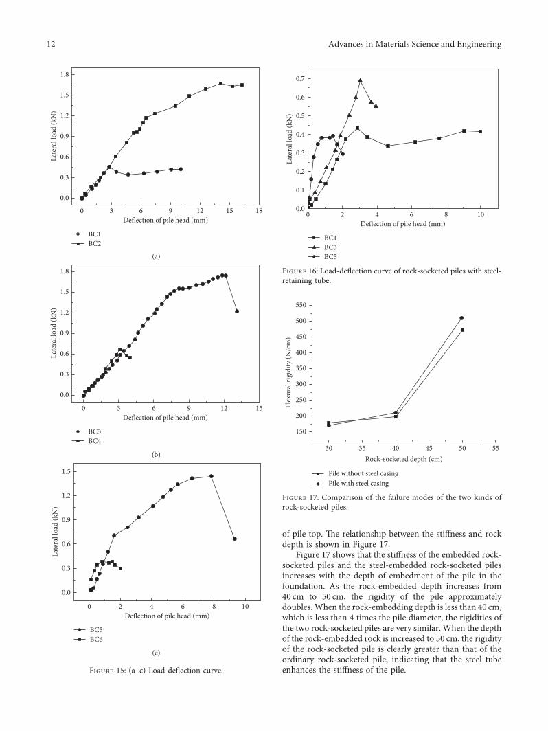