experimental and numerical study on behavior of … and numerical study on behavior of externally...
TRANSCRIPT
International Journal of Engineering Research and Technology. ISSN 0974-3154 Volume 8, Number 1 (2015), pp. 55-65
© International Research Publication House
http://www.irphouse.com
Experimental and Numerical Study on Behavior of
Externally Bonded RC Beams Using FRP Composites
M. M. Deshmukh1, D. D. Mohite2, Dr. C. P. Pise3, S. S. Kadam2, Y. P. Pawar2,
C. M. Deshmukh2
1PG Student, Dept. of Civil Engineering,
SKN Sinhgad College of Engineering, Pandharpur. 2Assistant Professor, Dept. of Civil Engineering,
SKN Sinhgad College of Engineering, Pandharpur. 3Associate Professor & HOD, Dept. of Civil Engineering,
SKN Sinhgad College of Engineering, Pandharpur.
Email: [email protected]
Abstract
This paper explores the flexural behaviour of carbon fiber reinforced polymer
(CFRP) strengthened reinforced concrete (RC) beams of M-20 grade of
concrete. The experimental programe consists of strengthening and testing of
simply supported rectangular beam of size 150mm X 150mm X 700 mm strengthened with CFRP sheets. For flexural strengthening of RC beams, total
eight beams were cast and tested over an effective span of 600 mm up to
failure under static loads. Seven beams were strengthened with bonded CFRP
fabric in single layer which are parallel to beam axis with different pattern and tested until failure; the remaining one beam was used as control beam. Static
responses of all the beams were evaluated in terms of strength, load vs
displacement curve and the associated failure modes. The theoretical strength
and the load - displacement response of the strengthened beams and control beams were predicted by using FEA software ANSYS 14. Comparison has
been made between the numerical (ANSYS 14) and the experimental results.
The results show that the strengthened beams exhibit increased flexural
strength, load carrying capacity, and composite action until failure. Thus it is a feasible method for strengthening and retrofitting of RC beams.
1) INTRODUCTION A structure is designed for a specific period and depending on the nature of the
structure, its design life varies. For a domestic building, this design life could be as
56 M. M. Deshmukh et al
low as twenty - five years, whereas for a public building, it could be fifty years.
Deterioration in concrete structures is a major challenge faced by the infrastructure and bridge industries worldwide. The deterioration can be mainly due to
environmental effects, which includes corrosion of steel, gradual loss of strength with
ageing, repeated high intensity loading, variation in temperature, freeze - thaw cycles,
contact with chemicals and saline water and exposure to ultra - violet radiations. As complete replacement or reconstruction of the structure will be cost effective,
strengthening or retrofitting is an effective way to strengthen the same.
The most popular techniques for strengthening of RC beams have involved the use of
external epoxy - bonded steel plates. It has been found experimentally that flexural strength of a structural member can increase by using this technique. Although steel
bonding technique is simple, cost - effective and efficient, it suffers from a serious
problem of deterioration of bond at the steel and concrete interphase due to corrosion
of steel. Other common strengthening technique involves construction of steel jackets which is quite effective from strength, stiffness and ductility considerations. However,
it increases overall cross-sectional dimensions, leading to increase in self-weight of
structures and is labour intensive. To eliminate these problems, steel plate was
replaced by corrosion resistant and light - weight FRP Composite plates. FRPs help to increase strength and ductility without excessive increase in stiffness. Further, such
material could be designed to meet specific requirements by adjusting placement of
fibres. So concrete members can now be easily and effectively strengthened using
externally bonded FRP composites. Advanced fibre reinforced polymer (FRP) composite is very effectively being used
worldwide for strengthening structures. It provides a cost effective and technically
more superior alternative to the traditional techniques in many specific situations. It
offers high strength with low self weight, corrosion resistance, high fatigue resistance, easy and rapid installation and minimal change in structural geometry. Conventional
strengthening methods such as external post tensioning, member enlargement along
with internal transverse steel, and bonded steel plates are very expensive. In addition
to that these methods are time consuming; require extensive equipment and significant labour. FRP repair systems provide an economical and technically better
alternative to traditional repair systems and materials. Literature survey indicates
there is considerable scope for research work in this area of “strengthening of beams
with FRP composites”.
2) EXPERIMENTAL IVESTIGATION
2.1 Details of the Beam Specimen:- The test program consisted of casting and testing of eight beams, of which one was
control beams, all having size of 150 mm X 150 mm X 700 mm length, reinforced
with 2 - 10 ɸ at bottom, 2 - 10 ɸ at top using 6mm diameter stirrups @ 120 mm c/c
. The beams were cast using M 20 grade concrete and Fe 500 grade steel. The casting of beams was made as per IS code specification using M 20 grade concrete with 20
mm maximum size of coarse aggregate, locally available sand and 53 grade ordinary
portland cement [ III - 3]. These beams were cured for 28 days in pure water and were
Experimental and Numerical Study on Behavior 57
tested under two-point loading on a universal testing machine of capacity 1000 KN
[III - 4].
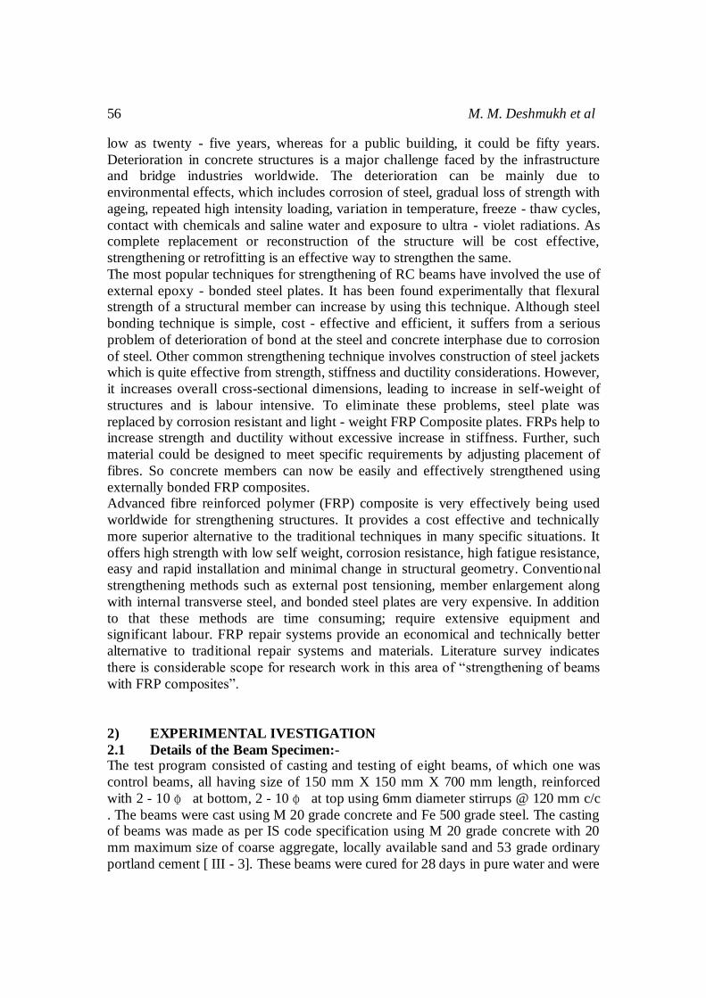
2.2 Preparation of Test Specimen:- The description of test specimens is summarized in Table 1. The surfaces of the
beams were cleaned using polish paper or grind to ensure a good bond between the FRP strip and concrete surface. Each of these beams was externally bonded with
CFRP strips and epoxy to the beam as per the procedure given by the manufacturer.
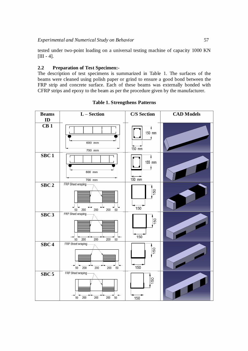
Table 1. Strengthens Patterns
Beams
ID
L – Section C/S Section CAD Models
CB 1
SBC 1
SBC 2
SBC 3
SBC 4
SBC 5
58 M. M. Deshmukh et al
SBC 6
SBC 7
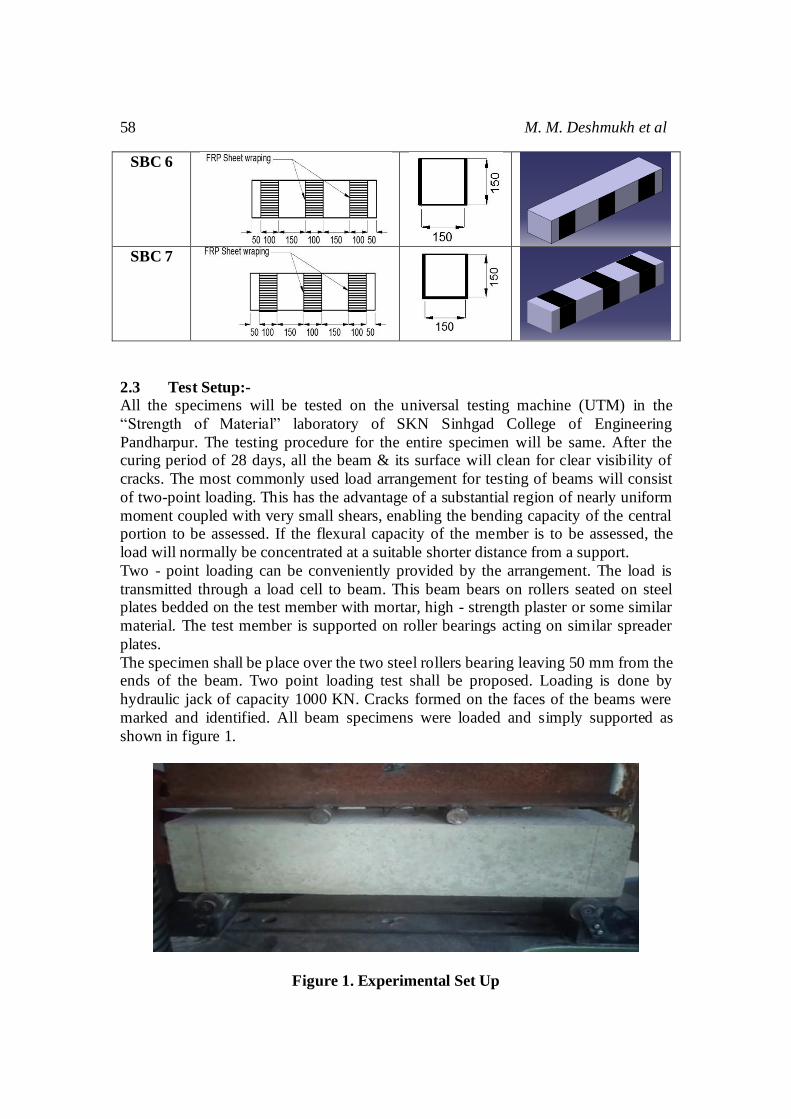
2.3 Test Setup:- All the specimens will be tested on the universal testing machine (UTM) in the
“Strength of Material” laboratory of SKN Sinhgad College of Engineering
Pandharpur. The testing procedure for the entire specimen will be same. After the curing period of 28 days, all the beam & its surface will clean for clear visibility of
cracks. The most commonly used load arrangement for testing of beams will consist
of two-point loading. This has the advantage of a substantial region of nearly uniform
moment coupled with very small shears, enabling the bending capacity of the central portion to be assessed. If the flexural capacity of the member is to be assessed, the
load will normally be concentrated at a suitable shorter distance from a support.
Two - point loading can be conveniently provided by the arrangement. The load is
transmitted through a load cell to beam. This beam bears on rollers seated on steel plates bedded on the test member with mortar, high - strength plaster or some similar
material. The test member is supported on roller bearings acting on similar spreader
plates.
The specimen shall be place over the two steel rollers bearing leaving 50 mm from the ends of the beam. Two point loading test shall be proposed. Loading is done by
hydraulic jack of capacity 1000 KN. Cracks formed on the faces of the beams were
marked and identified. All beam specimens were loaded and simply supported as
shown in figure 1.
Figure 1. Experimental Set Up

Experimental and Numerical Study on Behavior 59
Load - deflection, stress and strains have been recorded for each specimen. Concrete
having mean cube compressive strength of 21.54 MPa was used. For all the test beams, the parameters of interest were ultimate load, mid-span deflection, composite
action, and failure modes.
2.4 Test Result:- During the experimental testing of beams it is observed that all the beams which
strengthened, there is considerable increase in load values for initial cracks. For
control beam initial cracks appeared at 35 KN and for all strengthen beam it was
about 62 to 70 KN.
Figure 2. Load vs Deflection Curve for CB 1 and SBC 1,2,3,4,5,6,7
2.5 Ultimate Load Carrying Capacity
The load carrying capacity of the control beams and the strengthen beams were
found out is shown in figure 3. The control beams were loaded up to their The control beams were loaded up to their ultimate loads. It was noted that of all
the beams, the strengthen beams SBC 1, SBC 2 and SBC 7 had the higher load
carrying capacity compared to the controlled beam. An important character to be
noticed about the usage of CFRP sheets is the high ductile behavior of the beams. The shear failure being sudden can lead to huge damage to the structure.
But the ductile behaviour obtained by the use of CFRP can give us enough
warning before the ultimate failure. The use of FRP can delay the initial cracks and
further development of the cracks in the beam.

60 M. M. Deshmukh et al
Figure 3. Ultimate Loads of Beams CB 1 and SBC 1,2,3,4,5,6,7
3) FINITE ELEMENT MODELING Simulation has been carried out in ANSYS 14 which is a finite element package. In
modeling 3D geometry of beams is drawn in CATIA 6 package. Concrete is a nonlinear behaviour material during loading, it is analysis in ANSYS
version 14.0 (workbench) to conduct analysis.
Figure 4. CAD Modelling of Beam
Similarly different configurations of beams which are modelled in CATIA 5.
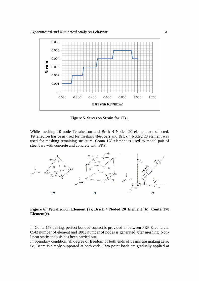
CAD model is imported in ANSYS and it is meshed. Before mesh material properties
are input to the software. Non-linear material properties are taken into consideration. These properties are obtained from experimentation. Following graph shows non
linear behaviour of CB 1.
Experimental and Numerical Study on Behavior 61
Figure 5. Stress vs Strain for CB 1
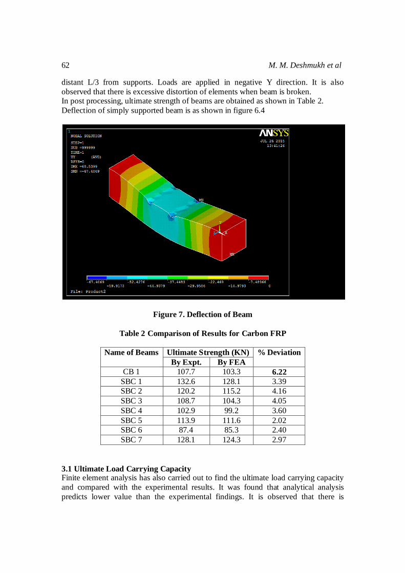
While meshing 10 node Tetrahedron and Brick 4 Noded 20 element are selected.
Tetrahedron has been used for meshing steel bars and Brick 4 Noded 20 element was
used for meshing remaining structure. Conta 178 element is used to model pair of steel bars with concrete and concrete with FRP.
Figure 6. Tetrahedron Element (a), Brick 4 Noded 20 Element (b), Conta 178
Element(c).
In Conta 178 pairing, perfect bonded contact is provided in between FRP & concrete.
8542 number of element and 1881 number of nodes is generated after meshing. Non-
linear static analysis has been carried out. In boundary condition, all degree of freedom of both ends of beams are making zero.
i.e. Beam is simply supported at both ends. Two point loads are gradually applied at
62 M. M. Deshmukh et al
distant L/3 from supports. Loads are applied in negative Y direction. It is also
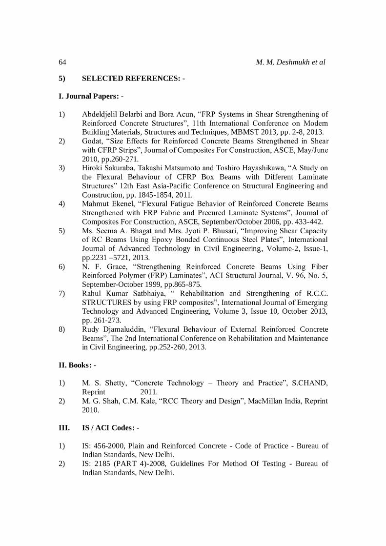
observed that there is excessive distortion of elements when beam is broken. In post processing, ultimate strength of beams are obtained as shown in Table 2.
Deflection of simply supported beam is as shown in figure 6.4
Figure 7. Deflection of Beam
Table 2 Comparison of Results for Carbon FRP
Name of Beams Ultimate Strength (KN) % Deviation
By Expt. By FEA
CB 1 107.7 103.3 6.22
SBC 1 132.6 128.1 3.39
SBC 2 120.2 115.2 4.16
SBC 3 108.7 104.3 4.05
SBC 4 102.9 99.2 3.60
SBC 5 113.9 111.6 2.02
SBC 6 87.4 85.3 2.40
SBC 7 128.1 124.3 2.97
3.1 Ultimate Load Carrying Capacity Finite element analysis has also carried out to find the ultimate load carrying capacity
and compared with the experimental results. It was found that analytical analysis
predicts lower value than the experimental findings. It is observed that there is

Experimental and Numerical Study on Behavior 63
maximum 6.22% deviation in ultimate strength obtained by experimentation and FEA.
From the results, it is observed that the maximum deviation in case of carbon fibers is 6.22%; whereas minimum deviation is 2.02%. The deviation, may occur because as
during software analysis it considers all the ideal conditions for analysis. As a matter
of fact practically or during experimentation work it is highly impossible to create
ideal conditions to perform the ideal lab work for preparation of concrete and during casting. The deviation may be consider the difference between ideal assumption and
actual work.
Figure 8. Comparison of Results for Carbon FRP (Expt. and FEA)
4) CONCLUSIONS:-
Based on the results obtained from experiments, and ANSYS analyses, the following
conclusions are drawn:
1) CFRP fabric properly bonded to the tension face of RC beams can enhance the flexural strength up to 23%.
2) At any given load level, the deflections are reduced significantly thereby
increasing the stiffness for the strengthened beams. At ultimate load level of
the control specimens, the strengthened beams exhibit a decrease of deflection. 3) Flexural strengthening of the beam increases the ultimate load carrying
capacity, but the cracks developed were not visible up to a higher load. Due to
invisibility of the initial cracks, it gives less warning compared to the control
beam. 4) Finite element analysis has been carried out for result validation. It is observed
that there is maximum 6.22% deviation in ultimate strength obtained by
experimentation and FEA.
5) It is observed that load at initial cracks was increased for all strengthening the beam.
64 M. M. Deshmukh et al
5) SELECTED REFERENCES: -
I. Journal Papers: -
1) Abdeldjelil Belarbi and Bora Acun, “FRP Systems in Shear Strengthening of
Reinforced Concrete Structures”, 11th International Conference on Modern Building Materials, Structures and Techniques, MBMST 2013, pp. 2-8, 2013.
2) Godat, “Size Effects for Reinforced Concrete Beams Strengthened in Shear
with CFRP Strips”, Journal of Composites For Construction, ASCE, May/June
2010, pp.260-271. 3) Hiroki Sakuraba, Takashi Matsumoto and Toshiro Hayashikawa, “A Study on
the Flexural Behaviour of CFRP Box Beams with Different Laminate
Structures” 12th East Asia-Pacific Conference on Structural Engineering and
Construction, pp. 1845-1854, 2011. 4) Mahmut Ekenel, “Flexural Fatigue Behavior of Reinforced Concrete Beams
Strengthened with FRP Fabric and Precured Laminate Systems”, Journal of
Composites For Construction, ASCE, September/October 2006, pp. 433-442.
5) Ms. Seema A. Bhagat and Mrs. Jyoti P. Bhusari, “Improving Shear Capacity of RC Beams Using Epoxy Bonded Continuous Steel Plates”, International
Journal of Advanced Technology in Civil Engineering, Volume-2, Issue-1,
pp.2231 –5721, 2013.
6) N. F. Grace, “Strengthening Reinforced Concrete Beams Using Fiber Reinforced Polymer (FRP) Laminates”, ACI Structural Journal, V. 96, No. 5,
September-October 1999, pp.865-875.
7) Rahul Kumar Satbhaiya, “ Rehabilitation and Strengthening of R.C.C.
STRUCTURES by using FRP composites”, International Journal of Emerging Technology and Advanced Engineering, Volume 3, Issue 10, October 2013,
pp. 261-273.
8) Rudy Djamaluddin, “Flexural Behaviour of External Reinforced Concrete
Beams”, The 2nd International Conference on Rehabilitation and Maintenance in Civil Engineering, pp.252-260, 2013.
II. Books: -
1) M. S. Shetty, “Concrete Technology – Theory and Practice”, S.CHAND,
Reprint 2011.
2) M. G. Shah, C.M. Kale, “RCC Theory and Design”, MacMillan India, Reprint
2010.
III. IS / ACI Codes: -
1) IS: 456-2000, Plain and Reinforced Concrete - Code of Practice - Bureau of Indian Standards, New Delhi.
2) IS: 2185 (PART 4)-2008, Guidelines For Method Of Testing - Bureau of
Indian Standards, New Delhi.

Experimental and Numerical Study on Behavior 65
3) IS: 10262-1982, Recommended Guidelines For Concrete Mix Design - Bureau
Of Indian Standards, New Delhi. 4) IS: 516:1959, Methods Of Test For Strength Of Concrete - Bureau Of Indian
Standards, New Delhi.
5) ACI 440.2R-02: Guide for the Design and Construction of Externally Bonded
FRP Systems for Strengthening Concrete Structures – American Concrete Institute – Effective from 11 July 2002.
6) ACI 440.2R-08 Guide for the Design and Construction of Externally Bonded
FRP Systems for Strengthening Concrete Structures – American Concrete
Institute – Effective from July 2008.

66 M. M. Deshmukh et al