experimental and numerical studies on the static de ection ... · experimental and numerical...
TRANSCRIPT

Mechanics and Mechanical Engineering
Vol. 20, No. 2 (2016) 97–108c⃝ Lodz University of Technology
Experimental and Numerical Studies on the Static Deflectionof the Composite Beam with the MFC Element
Jaros law GawrylukAndrzej MituraAndrzej Teter
Department of Applied MechanicsLublin University of Technology
Nadbystrzycka 36 St., PL-20-618 Lublin, [email protected]@[email protected]
Received (20 January 2015)
Revised (26 January 2016)
Accepted (21 February 2016)
In this paper the FE model of multi–layers composite beam with added Macro FiberComposite (MFC) active element is presented. At the first step of study the model ofthe MFC element was prepared. The experimental validation was made. Next, a staticdeflection of the composite beam with the actuator was calculated. The piezoelectriceffects was analyzed. The results of the FEM simulations were compared with theexperimental results. A very good agreement was achieved.
Keywords: Finite Element Method, structure, laminate, actuator, PZT, MFC.
1. Introduction
The active structure consists of load–bearing elements and active elements. Thesesensors track the real–time behavior of the structure. On the other hand, the ac-tuators can change their behavior. There are a lot of different type of the activeelements. The shape memory alloys (SMA), magnetorheological materials (MR),piezoelectric (PZT) and Macro Fiber Composite (MFC) elements can be used. Thebasic problem is selection of the active element for analyzed structure and verifica-tion of the effectiveness of its actions. The aim of this paper was to build numericalmodel of multi-layered composite beam with embedded MFC active element usingthe finite element method (FEM). The static deflection of the composite cantileverbeam with MFC element for different voltage applied to the terminal transducer wasstudied. Results of the FEM analysis has been verified in experimental study. De-tailed simulations were performed using the commercial software package Abaqus.

98 Gawryluk, J., Mitura, A. and Teter, A.
In this software there are special elements to describe the electromechanical effect.The prepared numerical model of the composite beam with the piezoelectric elementwas used for further dynamic simulations in order to determine rightly applicationof the transducer for damping of vibrations of thin-walled composite structures.
In the literature one can find many works dealing with the application of activeelements and their use for analysis structures as well as the active structured be-havior in real time. However, there is a lack of works in which the behavior changeof the composite structure was caused by the MFC active element.
The results of research were performed so far and published by the authors [1–13] confirm a high suitability of piezoelectric and MFC type elements for structuralhealth monitoring and control in real time. In the paper [4] we presented our staticanalysis for cantilever beammade of two layers of PVDF. Some different applicationsof these active elements were presented by other authors, for example: vibrationsuppression, energy harvesting etc. [14–24]. Macro Fiber Composite actuators arecharacterized by large deformation and large forces generated there. The interest ofthis type of actuators is due to their low weight, resistance to temperature change,high flexibility, short time operation and high conversion efficiency of the electricenergy into the mechanical one. This effect in MFC type element causes change inthe electric field, next it has influence on the deformation, which change the densityof charge and the electric field.
In order to determine the behavior of intelligent element a finite element methodseems to be a good choice [25–28].
2. Numerical Model of Active Element
Detailed calculations were made for a cantilever beam made of glass-epoxy unidirec-tional composite prepreg with Macro Fiber Composite (MFC) active element. TheM8528-P1 element made by Smart Material Corp., USA [29] was used. This was thetransducer of the d33 effect type. This PZT effect corresponds to the deformationof a specimen in the direction of the driving electric field.
The constitutive equations describing the piezoelectric property are the follow-ing:
{ε} = [S]{σ}+ [d]{E} (1)
where: {ε} – the strain vector, {σ} – the stress vector, {E} – components of theelectric field strength, [S] – the compliance matrix, [d] – the matrix of piezoelectriccoefficients.
In this case, it was assumed that the intensity of the electric field E3 acts onlyalong the x3 axis (denote as z axis). The piezoelectric effect d33 is clarified in Fig. 1.
The extension ∆a of the free element in axis x3 can be written as:
∆a = d33E3a (2)
where: d33 – the electromechanical coupling coefficient in the direction 3, a – thelength of the free active element, E3 – the electric field.
The strain in direction x3 equals to:
ε33 = d33U
a(3)

Experimental and Numerical Studies on the Static Deflection ... 99
The geometrical dimensions of the transducer were: the length – 103 mm (85 mm),the width – 35 mm (28 mm), the thickness – 0.3 mm ±10%. Dimensions of theactive area of this element were given in brackets. The mechanical properties ofthe M8528-P1 element are presented in Tab. 1 [29]. It is orthotropic linear elasticmaterial. The shear modulus was estimated using the rule–of–mixtures.
Figure 1 The d33 effect for piezoelectric material
Table 1 The mechanical properties of M8528-P1 element [29]
Parameter ValueYoung modulus [ MPa]
E3 30 336E2 15 857
Poisson’s ratio [-]ν23 0.31
Shear modulus [MPa]G23 5 515Density [kg/m3]ρ 5 440
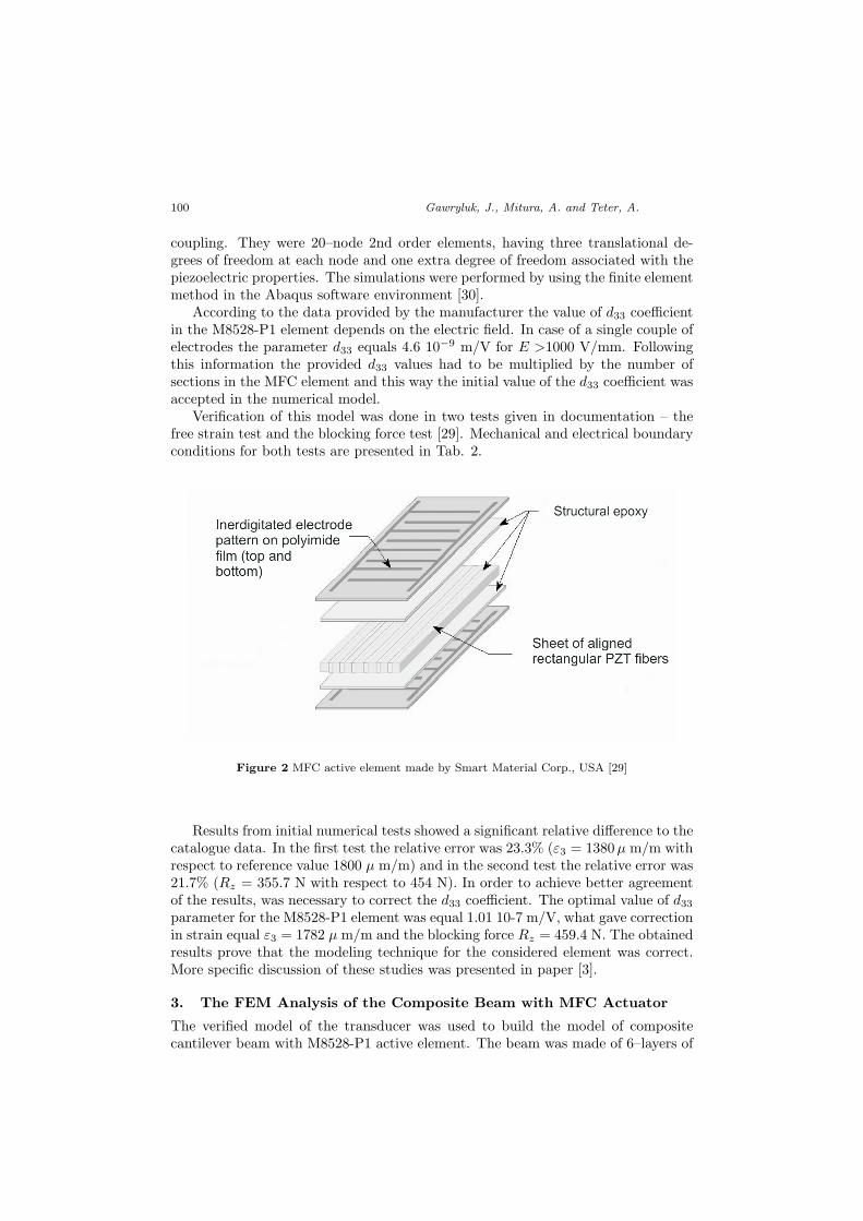
The MFC active element consist of PZT fibers isolated from each other (170sections of electrocouples distant by 0.5mm one from another) embedded in theepoxy resin (see Fig. 2). Therefore, the necessity arose to build a model of continu-ous supplementary element, which electrical will be identical to the one of the realelement.
FEM modeling assumed that there is a piezoelectric material on the whole areaof element. The numerical model of actuator was constructed using the C3D20Etype solid elements. They made it possible to model effect of electromechanical
100 Gawryluk, J., Mitura, A. and Teter, A.
coupling. They were 20–node 2nd order elements, having three translational de-grees of freedom at each node and one extra degree of freedom associated with thepiezoelectric properties. The simulations were performed by using the finite elementmethod in the Abaqus software environment [30].
According to the data provided by the manufacturer the value of d33 coefficientin the M8528-P1 element depends on the electric field. In case of a single couple ofelectrodes the parameter d33 equals 4.6 10−9 m/V for E >1000 V/mm. Followingthis information the provided d33 values had to be multiplied by the number ofsections in the MFC element and this way the initial value of the d33 coefficient wasaccepted in the numerical model.
Verification of this model was done in two tests given in documentation – thefree strain test and the blocking force test [29]. Mechanical and electrical boundaryconditions for both tests are presented in Tab. 2.
Figure 2 MFC active element made by Smart Material Corp., USA [29]
Results from initial numerical tests showed a significant relative difference to thecatalogue data. In the first test the relative error was 23.3% (ε3 = 1380µ m/m withrespect to reference value 1800 µ m/m) and in the second test the relative error was21.7% (Rz = 355.7 N with respect to 454 N). In order to achieve better agreementof the results, was necessary to correct the d33 coefficient. The optimal value of d33parameter for the M8528-P1 element was equal 1.01 10-7 m/V, what gave correctionin strain equal ε3 = 1782 µ m/m and the blocking force Rz = 459.4 N. The obtainedresults prove that the modeling technique for the considered element was correct.More specific discussion of these studies was presented in paper [3].
3. The FEM Analysis of the Composite Beam with MFC Actuator
The verified model of the transducer was used to build the model of compositecantilever beam with M8528-P1 active element. The beam was made of 6–layers of

Experimental and Numerical Studies on the Static Deflection ... 101
Table 2 The boundary conditions in numerical model validation
Boundary conditions Freestrain
Blockingforce
One surface in XY plane supportedin Oz direction
X X
The bottom surface in YZ plane supportedin Ox direction
X X
One whole edge in XZ plane supportedin Oy direction
X X
Charge potential 0 V is applied on one surfacein XY plane
X X
Charge potential 1500 V is applied on second surfacein XY plane
X X
On the second surface in XY plane supportedin Oz direction
- X
glass–epoxy unidirectional composite prepreg with configuration of composite plies[45/-45/90]s. The material data for the laminate was determined in accordance withthe standard ISO tests and was presented in Table 3. Additionally, a theoreticalrelationship for the material constants can be written:
E2ν32 = E3ν23 (4)
Active element was adhered on one face of the beam only, directly at the clampedend. The geometrical dimensions of the beam are presented in Fig. 3.
Figure 3 Schematic of the composite cantilever beam (dimensions in mm)
The model of the cantilever beam (Fig. 4) was constructed with the C3D20REtype solid elements. They are 20–node 2nd order (with a square shape function)elements, having three translational degrees of freedom at each node. All the el-ements used a reduced integration method. Individual layers of the laminate had

102 Gawryluk, J., Mitura, A. and Teter, A.
Table 3 Mechanical properties of glass–epoxy composite
Parameter ValueYoung modulus [MPa]
E3 46 430E2 14 926
Poisson’s ratio [-]ν23 0.27
Shear modulus [MPa]G23 5 233Density [kg/m3]
ρ 2 032
been modeled according to Layup–ply technique. The mechanical boundary con-ditions for the model of the beam were realized by restraining the nodes locatedat one end of the beam all degrees of freedom. The combination of all parts wasrealized by defining interactions as ”TIE”, what resulted in linking the degrees offreedom of the nodes in contact on the appropriate surfaces of the model [30].
Figure 4 FEM model of the cantilever beam with the composite stacking sequence [45/-45/90]s
During numerical analysis, the static deflection of the composite cantilever beamwith the MFC element was determined. Subsequent loadings within the range of 0-1000 V were applied to the positive terminal transducer, keeping the constant valueof 0 V at a negative one. Deflections of the beam were calculated by reporting thevertical displacement (axis Ox ) of the free end of the beam.
4. Experimental Study
Experimental study was performed on the special experimental setup. Diagramof the measuring system was shown in Fig.5; it consists of several subsystems.The first–being the main object is the multilayer composite beam with the MFCactuator. It was installed in a holder. The second subsystem was used to supply thepiezoelectric actuator. It had two elements: a high–voltage amplifier and a signal

Experimental and Numerical Studies on the Static Deflection ... 103
generator. Both devices together provided a change of voltage applied to control ofthe MFC in an open loop (without feedback). The vibration of the free end of thebeam can be monitored by the measuring subsystem. To measure the response of themechanical part the laser triangulation sensor was used. The signals from the sensorand the generator were transmitted to the recorder. In the applied experimentalsetup for recording and saving data the MGC+ device was used, connected to a PCcomputer.
Figure 5 Diagram of measuring system
During the experimental study the responses of the beam were obtained. Full testcycle U(t) can be described mathematically using the Heaviside’s step functionH(...):
U(t) = A ·H(s(t)), (5)
where: A is the step level and s(t) is a new coordinate depending on time
s(t) = 300− mod(t, 600), (6)
where the function mod(. . . ) is a modulo operation. Interpretation of the examplingtest cycle was performed in the Matlab software and is shown in Fig. 6.
Experimental tests were made at the levels A from 100 V to 1000 V (Eq. 5). Inthis paper two cases are presented: for the voltage 700 V and 1000 V (Figs. 7–8).These pictures show only one cycle of the step function change. One can observe twoeffects. The first, free damped vibrations oscillations after jump values of the voltagefrom 0 to A and vice versa. The vibrations quickly disappear. The second effect isa creep of piezoelectric elements, which is seen as a slow change in displacement ofthe free beam end.

104 Gawryluk, J., Mitura, A. and Teter, A.
Figure 6 Step excitation of the MFC actuator power supply (A = 100 V)
a) b)
Figure 7 Voltage signal of power supply (a) and vertical deflection of the free end of the beamfor voltage 700 V (b)

Experimental and Numerical Studies on the Static Deflection ... 105
a) b)
Figure 8 Voltage signal of power supply (a) and vertical deflection of the free end of the beamfor voltage 1000V (b)
Figure 9 Static deflection of the beam for four cases of applied voltage
Figure 10 Maximum deflection of the composite beam for both studies

106 Gawryluk, J., Mitura, A. and Teter, A.
5. Comparison of the results
As a result of static numerical analysis the static deflection of the beam (Fig. 9) forfour cases of the applied voltage: 250 V, 500 V, 750 V and 1000 V was obtained. Theresults of experimental analysis were shown in Figs. 7–8. These pictures presentedvertical deflection of the free end of the beam for voltage 700 V and 1000 V.
Comparison of static deflections obtained with the FEM simulations and theexperimental studies was presented in graph (Fig. 10). Specific results of bothanalyses was shown in Tab. 4.
Table 4 Comparison of deflections obtained with the FEM simulations and the experimentalstudies
U[V]Experiment FEM Relative Difference
[mm] [mm] [%]100 0.795 0.799 0.5200 1.590 1.599 0.6300 2.385 2.398 0.5400 3.180 3.197 0.5500 3.975 4.000 0.6600 4.770 4.799 0.6700 5.565 5.598 0.6800 6.360 6.397 0.6900 7.155 7.196 0.61000 7.950 7.995 0.6
A very good agreement between the FEM and the experimental results wasachieved. For the examined points the calculated differences did not exceed 1%.
6. Conclusion
The paper presents numerical and experimental studies of static deflection of thecomposite beam with the MFC active element. The static deflection of the com-posite cantilever beam with the MFC element for different voltage applied to theterminal transducer was determined. A very good agreement between the FEMand the experimental results was achieved. For the examined points the calculateddifferences did not exceed 1%, which confirmed the correctness of the numericalmodeling of the MFC active element. The numerical simulations were performedwith the commercial FE system Abaqus. The prepared numerical model of thecomposite beam with piezoelectric element will be used in further simulations, forexample: modal analysis, reducing vibration or damping of different characteristics.In the second stage a similar analysis for cantilever beam with the M8528-P2 activeelement will be done. This tape of active element uses d31 effect. A comparison ofboth analyses will show the effectiveness and the properties of active elements.

Experimental and Numerical Studies on the Static Deflection ... 107
Acknowledgements
This paper was financially supported by the Ministerial Research Project No. DEC-2012/07/B/ST8/03931 financed by the Polish National Science Centre.
References
[1] Bauchau, O. and Hong, C.: Finite element approach to rotor blade modeling,Journal of the American Helicopter Society, 32(1), 60–67, 1987.
[2] Chesne, S., Jean–Mistral, C. and Gaudiller, L.: Experimental identification ofsmart material coupling effects in composite structures, Smart Materials and Struc-tures , 22(10), 1–10, 2013.
[3] Latalski, J.: Modelling of macro fiber composite piezoelectric active elementsin ABAQUS system, Eksploatacja i Niezawodnosc - Maintenance and Reliability, 4,72–78, 2011.
[4] Teter, A., Gawryluk, J. and Warminski, J.: An influence of the d311 effect onthe behavior of the cantilever beam–shaped piezoelectric activator made of two layersof PVDF with inverse polarity, Applied Computer Sience, 10(3), 23–33, 2014.
[5] Latalski, J., Warminski, J. and Georgiades, F.: Mode shapes variation of acomposite beam with piezoelectric patches, Transactions of the Institute of Aviation,218, 36–43, 2011.
[6] Mahesh, N. and Raghu, T.: Modular analysis of main rotor blade of light helicopterusing FEM, International Journal of Engineering Research & Technology, 4(5), 1492–1496, 2015.
[7] Nechibvute, A., Chawanda, A. and Lunhanga, P.: Finite element modeling ofa piezoelectric composite beam and comparative performance study of piezoelectricmaterials for voltage generation, International Scholarly Research Network MaterialsScience, 1–11, 2012.
[8] Nestorovic, T., Durrani, N. and Trajkov, M.: Experimental model identificationand vibration control of a smart cantilever beam using piezoelectric actuators andsensors, Journal of Electroceramics, 29, 42–55, 2012.
[9] Nestorovic, T., Marinkovic, D., Shabadi, S. and Trajkov M.: User definedfinite element for modeling and analysis of active piezoelectric shell structures, Mec-canica, 49, 1763–1774, 2014.
[10] Nestorovic, T., Shabadi, S., Marinkovic, D. and Trajkov M.: Modeling ofpiezoelectric smart structures by implementation of a user defined shell finite element,Facta Universitatis, Mechanical Engineering, 11(1), 1–12, 2013.
[11] Nestorovic, T. and Trajkov, M.: Active control of smart structures – an overallapproach., Facta Universitatis, Architecture and Civil Engineering, 8(1), 35–44, 2010.
[12] Sadilek, P. and Zemcik, R.: Frequency response analysis of hybrid piezoelectriccantilever beam, Engineering mechanics, 17(2), 73–82, 2010.
[13] Sartorato, M., De Medeiros, R. and Tita, V.: A finite element for active compos-ite plates with piezoelectric layers and experimental validation, Blucher MechanicalEngineering Proceedings, 1(1), 2867–2883, 2014.
[14] Borowiec, M.: Energy Harvesting of Cantilever Beam System with Linear and Non-linear Piezoelectric Model, European Physical Journal – Special Topics, 224, 2771–2785, 2015.

108 Gawryluk, J., Mitura, A. and Teter, A.
[15] Borowiec, M., Litak, G., Friswell, M. I. and Sondipon, A.: Energy Harvest-ing in a Nonlinear Cantilever Piezoelastic Beam Sysem Excited by Random VerticalVibrations, International Journal of Structural Stability and Dynamics, 14(8), 1–13,2014.
[16] De Marqui Junior, C., Erturk, A. and Inman, D. J.: An electromechanicalFinite Element Model for Piezoelectric Energy Harvester Plates, Journal of Soundand Vibration, 327, 9–25, 2009.
[17] Ghareeb, N. and Schmidt, R.: Active Control of a Reduced Model of a SmartStructure, 10(3), Tech Science Press, 177–199, 2013.
[18] Kumar, S., Srivastava, R. and Srivastava, R.K.: Active Vibration Control ofSmart Piezo Cantilever Beam using PID Controller, International Journal of Researchin Engineering and Technology, 3(1), 392–399, 2014.
[19] Mitura, A., Kazmir, T., Warminski, J., Augustyniak, M. and Jarzyna,W.: Vibration Suppression of Composite Plate with MFC Active Elements, MachineDynamics Research 34(2), 86–92, 2010.
[20] Mitura, A, Warminski, J, Bochenski, M.: Active vibration suppression by ap-plication of macro fiber composite, Machine Dynamics Research, 35(2), 55–61, 2011.
[21] Najeeb ur Rahman and Naushad Alam M.: Active Vibration Control of aPiezoelectric Beam using PID Controller: Experimantal Study, Latin American Jouralof Solids and Structures, 9, 657–673, 2012.
[22] Nestorovic, T. and Trajkov, M.: Optimal Actuator and Sensor Placement Basedon Balanced Reduced Models, Mechanical Systems and Signal Processing, 36, 271–289, 2013.
[23] Sodano, H. A., Park, G. and Inman D. J.: An investigation into the perfor-mance of macro–fiber composites for sensing and structural vibration applications,Mechanical Systems and Signal Processing, 18, 683–697, 2004.
[24] Warminski, J., Bochenski, M., Jarzyna, W., Filipek, P. and Augustyniak,M.: Active suppression of nonlinear composite beam vibrations by selected controlalgorithms, Communications in Nonlinear Science and Numerical Simulation, 16(5),2237–2248, 2011.
[25] Matthews, F., Davis, G., Hitchings, D. and Soutis, C.: Finite Element Mod-eling of Composite Materials and Structures, Woodhead Publishing Series, 2000.
[26] Piefort, V.: Finite element modeling of piezoelectric active structures, Master’s the-sis, Faculty of Applied Sciences, Universit’e Libre de Bruxelles, 2001.
[27] Tenek, L. and Argyris, J.: Finite Element Analysis for Composite Structures,Springer, London, 1998.
[28] Varadan, V. K., Vinoy, K. J. and Gopalakrishnan, S.: Smart Material Sys-tem and MEMS: Design and Development Methodologies, John Wiley & Sons Ltd,England, 2006.
[29] Smart Material, http://www.smart-material.com/MFC-product-main.html /(28.12.2015)
[30] Abaqus 6.14 documentation