experimental and numerical investigation of ply size
TRANSCRIPT

Delft University of Technology
Experimental and numerical investigation of ply size effects of steel foil reinforcedcomposites
Keller, A.; Geissberger, R.; Studer, J.; Leone, F.; Stefaniak, D.; Pascoe, J. A.; Dransfeld, C.; Masania, K.
DOI10.1016/j.matdes.2020.109302Publication date2021Document VersionFinal published versionPublished inMaterials and Design
Citation (APA)Keller, A., Geissberger, R., Studer, J., Leone, F., Stefaniak, D., Pascoe, J. A., Dransfeld, C., & Masania, K.(2021). Experimental and numerical investigation of ply size effects of steel foil reinforced composites.Materials and Design, 198, [109302]. https://doi.org/10.1016/j.matdes.2020.109302
Important noteTo cite this publication, please use the final published version (if applicable).Please check the document version above.
CopyrightOther than for strictly personal use, it is not permitted to download, forward or distribute the text or part of it, without the consentof the author(s) and/or copyright holder(s), unless the work is under an open content license such as Creative Commons.
Takedown policyPlease contact us and provide details if you believe this document breaches copyrights.We will remove access to the work immediately and investigate your claim.
This work is downloaded from Delft University of Technology.For technical reasons the number of authors shown on this cover page is limited to a maximum of 10.

Materials and Design 198 (2021) 109302
Contents lists available at ScienceDirect
Materials and Design
j ourna l homepage: www.e lsev ie r .com/ locate /matdes
Experimental and numerical investigation of ply size effects of steel foilreinforced composites
A. Keller a, R. Geissberger a, J. Studer a, F. Leone a, D. Stefaniak b, J.A. Pascoe c, C. Dransfeld a,c, K. Masania a,c,⁎a Institute of Polymer Engineering, University of Applied Sciences and Arts, Northwestern Switzerland, Klosterzelgstrasse 2, 5210 Windisch, Switzerlandb German Aerospace Centre (DLR), Institute for Composite Structures and Adaptive Systems, Lilienthalplatz 7, 38108 Braunschweig, Germanyc Faculty of Aerospace Engineering, Delft University of Technology, Kluyverweg 1, 2629 HS Delft, the Netherlands
H I G H L I G H T S G R A P H I C A L A B S T R A C T
• Thick and thin-ply CFRP laminates weremechanically characterized with andwithout steel foil reinforcement.
• Local steel foil reinforcement aroundholes can overcome the notch sensitiv-ity of thin-ply composites.
• The onset (0.5%) and 2% bearingstrength of the thick-ply CFRP weremore than doubled with the additionof steel foils.
• Onset bearing strength of the hybridCFRP are also higher than the ultimatestrength of the pure CFRP.
• Ply thicknesses may be tuned to gener-ate stable damage propagation in thehybrid configuration.
⁎ Corresponding author at: Institute of Polymer EngiSciences and Arts, Northwestern Switzerland, KlosterzSwitzerland.
E-mail address: [email protected] (K. Masania).
https://doi.org/10.1016/j.matdes.2020.1093020264-1275/© 2020 The Authors. Published by Elsevier Ltd
a b s t r a c t
a r t i c l e i n f oArticle history:Received 11 October 2020Received in revised form 4 November 2020Accepted 5 November 2020Available online 7 November 2020
Keywords:Fibre metal laminatesThin ply compositesOpen hole damage
The effect of ply thickness on the notch sensitivity and bearing properties on carbon fibre reinforced polymercomposites and their hybrid laminates with steel foils were studied. Laminates with ply thicknesses of 0.3 mmand 0.03 mm comprising of CFRP and hybrid laminates were manufactured and characterized using tension,open hole tension and double lap bearing tests. A 25% ply substitution was found to double the bearing loadwith extensive plastic deformation in the joint while maintaining high stress and maintaining constantcross-sectional thickness in the laminate. With a good agreement between the finite element predicted valuesand failure behaviour, the damage initiation and progression behaviour could be observed experimentally. Wenumerically captured (i) rapid failure of 0° plies in the thin ply CFRP hybrid and (ii) continuous delaminationwith significant plastic deformation for the thick ply CFRP hybrid. The numerical results significantly reduce fu-ture experimental work when designing hybrid laminates and could allow the laminate lay-up to be tailored forload cases. Both the experiments and numerical models underline the distinct size effects occurring with respectto the ply thicknesses when hybridising a very ductile metal with a brittle yet strong composite material.
© 2020 The Authors. Published by Elsevier Ltd. This is an open access article under the CC BY license (http://creativecommons.org/licenses/by/4.0/).
neering, University of Appliedelgstrasse 2, 5210 Windisch,
. This is an open access article under
1. Introduction
Aerospace structures are typically composed of carbon fibre-reinforced thermosetting polymers (CFRP) to reduceweight and hencereduce emissions during operation [1]. The high anisotropy of CFRP
the CC BY license (http://creativecommons.org/licenses/by/4.0/).

Table 1Material designation and lay-up of the carbon fibre and hybrid laminates.
Sample Layup Ply thickness (mm) Density (kg/dm3)
Thin_CFRP [90°,45°,0°,-45°]10s 0.03 1.6Thick_CFRP [90°,45°,0°,-45°]s 0.3 1.6Thin_Hybrid [St,45°,0°,-45°]10s 0.03 3.18Thick_Hybrid [St,45°,0°,-45°]s 0.3 3.18
A. Keller, R. Geissberger, J. Studer et al. Materials and Design 198 (2021) 109302
require diverse and complex layups, which are designed depending onthe load case of the structure and usually exhibit a multi-directionalfibre directions. To achieve these orientations in a cost effectivemanner,automated manufacturing methods such as tape laying, pultrusion orresin transfer moulding (RTM) are used to build the laminates and tocreate sub-components that are then joined together [2]. However, therelatively low bearing strength of CFRPs means that the laminate hasto be thickened in order to have sufficient joint strength. An option toovercome thick laminates is to only locally increase the thickness ofthe structure, rather than sizing the entire laminate. Studer et al. showedthat co-curing of doublers allow for an increase in the local bearingstrengthwithout the addition of substantial weight to the structure [3].The drawback of this method is the increased load path eccentricity,which requires longer bolts and larger metallic fittings and introducessecondary bending. To avoid local thickening, hybridisation of the com-posites withmetals, into fibremetal laminates (FMLs), can be an attrac-tive solution. The metal layer lead to increased strength in the regionsthat require higher load carrying capacity, without a resulting change incross-section.Carbonfibrecompositeshavebeenhybridisedby titaniumfoil interleavingor substitution in the jointarea,with the latterbypassingthe need for local thickening of the composite material [4,5]. Steel foilshave become an attractive alternative because half of themetal volumeis needed compared to titanium foils in order to achieve the same bear-ingstrength at lowermaterial cost.More recently, steel foil hybridisationhas shown to improve the bearing strength of CFRP parts [6–9].
The development of thin ply technology has increased ply designfreedom, while offering materials with higher sustained stresses untilfirst ply failure. This size effect known as thin ply effect allows for de-layed matrix damage, delamination and first ply failure [10]. However,thin ply composites fail in a very brittle manner with little or no warn-ing and have shown high notch sensitivity [11–14]. The notch sensitiv-ity is attributed to the damage suppression and crack-propagationresistance [15]. Using acoustic emission Huang et al. [12] also observedthat delamination and matrix cracking during open hole tensile testswere indeed supressed in thin ply laminates.
Steel alloys could therefore be especially suitable as reinforcement inthin ply materials due to their low cost and their high stiffness, strengthand elongation at break [16]. Kötter et al. [17] showed that hybridisationof steel foil patches and thin-ply CFRP can improve the open hole tensileand compression strength up to about 30%, especially if applied locally[18–20]. Further work from Bosbach et al. [16] has shown that the addi-tion of metal layers can help to better detect defects when using struc-tural health monitoring to detect delamination.
These works show that the local placement of thin steel foils in crit-ical areas within the load path can reduce the notch sensitivity. The ef-fectiveness of the reinforcement depends on factors such as plythickness, steel alloy ductility, layup, and design of the transition area.In order to create an optimal laminate design, more understanding ofthe effect of these factors is needed. In addition, the ability to accuratelypredict the open hole tension strength for a given laminate design couldbe of great value.
The aimof this study is to generate thenecessaryunderstanding tobeable to design hybrid steel foil-CFRP laminates for open hole load cases.The effect of hybridisation of CFRP laminateswith ductile steel foils wasbothexperimentally andnumerically studied for twodifferentply thick-nesses. Ready to use finite element (FE)models were developed, whichcan be used to understand the effect of the steel foils, and to design theply-thickness and number of steel foils for optimal laminate perfor-mance. A simple analytical model was also developed to understand towhatextent theductilityof thesteel layerscanbeusedto improvethehy-brid laminate's failure strain and energy absorption capability.
2. Materials
The CFRP material used in this study [21] was a Toray M40JB Pre-preg, CFRP ThinPreg TM 80EP-736/CF, from North Thin Ply Technology
2
SARL, Switzerland, Two different ply areal weights were used, namely30 g/m2 (Thin) and 300 g/m2 (Thick). The prepregs were processedinto quasi-isotropic composites by a sequence of ply stacking into sub-units of 4, debulking for 30 min at 4 mbar and repeating until the lami-nate stackwas completed. The laminateswere cured using a hot press at80 °C and 0.6 MPa (6 bar) pressure for 8 h using a “LaboPress P200T”,Vogt, Germany. For the hybrid CFRP plates, austenitic CrNi-stainlesssteel 1.4310 at the equivalent thickness of the 90° ply in the substitutedlaminate (0.03 mm or 0.3 mm) was first prepared. A process very sim-ilar to the Boeing sol-gel surface treatmentwas adopted [22] to improvethe steel foil to CFRP adhesion. Following this process, the steel surfacewas degreased and then deoxidized by using a continuous vacuumblasting method. Finally, an aqueous sol-gel system, a dilute solutionof a stabilized alkoxy zirconiumorganometallic salt and an organosilanecoupling agent, was applied. The 90°-layers of the carbon fibre compos-ite were substituted with steel foils, as described in Table 1 and shownalso in the polished optical cross sections in Fig. 1.
3. Methods
3.1. Experimental
Samples for optical microscopy were prepared by embedding thesamples in epoxy and preparing them in a “TegraPol-21”, polishingma-chine from Struers GmbH, Switzerland. The samples were polishedusing a diamond polishing solution with a minimum particle size of0.25 μm in the paste. Images of the optical cross-sections were takenusing a “VKX-200”, Keyence, Germany, 3D laser scanning microscope.
Open hole tension tests were performed in accordance to ASTMD5766M-95 with an H6 6 mm hole. Unnotched tensile tests were alsoperformed, in accordance to ISO 527-00. A constant displacement rateof 1 mm/min was used for all samples, recording force and both ma-chine and extensometer displacement.
Double lap bearing tests were performed following ASTMD5961M-08, with 8 mm bearing fasteners (f9/H6 fit, class 12.9 highstrength steel). Again, a constant displacement rate of 1 mm/min wasused for all samples and the machine and extensometer displacementwere recorded.
A universal testingmachine fromWalter and Bai, Switzerland,with a100 kN capacity load cell of was used for all mechanical tests. The spec-imen gauge lengths were 24 mm for the open hole tensile andunnotched tensile tests, and 50 mm for the double lap bearing tests.
3.2. Numerical
Abaqus 6.1 (Dassault Sysèmes) was used to model a 3D explicitdamage model of both the CFRP and hybrid composites. The modelwas separated in distinct regions, which were individually formulated,as shown in Fig. 2(a). C3D8R hexagonal elementswere used in a quartergeometry continuummodel with an orthotropic material. A 3D damageVUSDFLD sub-routine with a Hashin 3D failure criterion [23] was usedwith a layered structure (shown in red in Fig. 2(a)). The steel foilsweremodelled as elastic-plastic material using a Johnson Cook [24] for-mulation for the 1.4310 austenitic stainless steel combined withexperimental data.

(a) Thin_CFRP (b) Thick_CFRP (c) Thin_Hybrid (d) Thick_Hybrid
Fig. 1. Polished optical sections of the carbon fibre and hybrid laminates. Steel foils are appear as white layers and are indicated by red arrows.
(a) (b)
(c)
Orthotropic Material, no damage
Layered structure,
3D damage subroutine
Individual strips,
connected by Cohesive Contact
Fiber breakage subroutine
Fig. 2. (a) Schematic of the developed quarter model with regions of varying complexity for the open hole tensile simulations, (b) element strain dependant degradation and (c) thequarter model for the bearing test simulations.
A. Keller, R. Geissberger, J. Studer et al. Materials and Design 198 (2021) 109302
3

Table 3Tensile and open hole tensile strength of the carbon fibre and hybrid laminates.
Sample Tensilestrength(MPa)
OHTstrength(MPa)
Specific OHT strength(MPa dm3 / kg)
Notchsensitivity
Thin_CFRP 750 ± 11 328 ± 7 205 2.29Thick_CFRP 554 ± 19 453 ± 49 283 1.22Thin_Hybrid 994 535 ± 6 168 1.86Thick_Hybrid 942 589 ± 40 185 1.60
A. Keller, R. Geissberger, J. Studer et al. Materials and Design 198 (2021) 109302
The element stiffness can be reduced using field variables. Whilethey are relatively easy to implement, they lack the ability to repli-cate the actual failure process. Therefore, to better model thestress-dependent elongation shown in Fig. 2(b), a strain dependant pro-gressive stiffness decrease was implemented. To do this, the stress wascalculated at each time step, the failure was checked using the 3DHashin criterion and the element stiffness was reduced accordingly.
The contact between the bolt and the laminates were modelledusing a penalty friction coefficient of 0.2 [25] in tangential direction. Ahard contact boundary condition was assigned in the normal direction.To account for the ability of fibres which fail in compression to still par-tially contribute to the laminate stiffness, the stiffness of the failed areaswas set to 30% of their original stiffness [26].
4. Results
4.1. Tensile and open hole tensile tests
The stiffness of the notched samples was significantly higher for thehybrid materials, due to the addition of the stiff steel layers (Table 2).
The ultimate tensile strength for unnotched Thin_CFRP andThick_CFRP was measured to be 750 ± 11 MPa and 554 ± 19 MPa, re-spectively, resulting in an increased strength of about 30% for the thin-ply laminates (Table 3). Steel foil hybridisation further increased thetensile strength to 994 MPa for the Thin_Hybrid and 942 MPa for theThick_Hybrid, showing a significant improvement in comparison tothe Thick_CFRP of 70%.
Despite the higher unnotched tensile strength, the Thin_CFRPshowed a significantly lower open hole tensile strength and hencehigher notch sensitivity, with a value of 328 MPa, 28% lower than theThick_CFRP with 453 MPa. Different failure behaviours were observedfor the CFRP composites, as shown in Fig. 3. In the Thin_CFRP samples,a near horizontal tensile crack was observed through the sample withdominant fibre fracture and little delamination present. The sampleswith conventional laminate ply thickness, however, showed delamina-tion prior to failure around the hole. Failurewas also observed in the 45°layers. As expected in the Thin_CFRP samples, the very thin plies supressdelamination, which reduces fibre pull-out and load redistribution dur-ing damage, leading to premature and brittle failure, as was also notedby Amacher et al. [10]. It can be seen in the stress-strain curves inFig. 4 that the stress in the Thin_CFRP increased linearly until failure,whereas in the Thick_CFRP a reduction in stiffness was observed beforethe ultimate stress. The stress peaks around the hole were reducedthrough matrix failure in the Thick_CFRP. The reduced notch sensitivityof the Thick_CFRP is related to the strong delamination, as during de-lamination the ±45° fibre plies align in the direction of load, whichwas also noticed in the hybrid laminates.
Hybridisation of the CFRP showed far greater contribution to im-provement of open hole strength for the Thin_Hybrid, which demon-strates that hybridisation helps to decrease the high notch sensitivityof thin-ply composites. While again, the open hole tensile strength ofthe Thick_Hybrid was higher with 589 MPa in comparison to 535 MPafor the Thin_Hybrid, the difference is less than for the pure CFRP sam-ples. The Thin_Hybrid failed catastrophically without plastic deforma-tion of the whole laminate, as can also be seen in the stress-strain
Table 2Open hole tensile stiffness of the carbon fibre and hybrid laminates.
Sample OHT stiffness (GPa) Specific OHT strength (GPa dm3/kg)
Thin_CFRP 58 ± 2 36Thick_CFRP 66 ± 12 41Thin_Hybrid 97 ± 9 30Thick_Hybrid 102 ± 6 32
4
curves in Fig. 4. Only a small non-linearity was observed for theThick_Hybrid. Necking of the steel plies was observed in theThick_Hybrid specimens but not in the Thin_Hybrid specimens, addingadditional evidence that there was more plastic deformation in theThick_Hybrid case.
The typical failures of the hybridmaterials are similar to those of theCFRP samples and can be seen in Fig. 3. Even though the specificstrength of thehybridisedmaterials is lower compared to theCFRP sam-ples, the strength gains and the pseudo-ductile failure behaviour couldjustify the use of steel foil localised around a hole, avoiding a significantweight penalty by allowing a reduced thickness in the rest of the part, aswill be discussed further in the Discussion section.
4.2. Double lap bearing tests
The double lap bearing onset (0.5% strain offset) strength of theThin_CFRP and Thick_CFRP were measured to 457 MPa and 356 MPa,respectively, resulting in a 28% higher strength of the Thin_CFRP(Fig. 5). The suppression of transverse cracking and delamination inthe Thin_CFRP that was observed in the tensile tests has similarly im-proved the bearing performance of the composite material.
Increased bearing strengthwasmeasured for both hybrid laminates.The onset strength for the Thick_Hybrid (803±76MPa)wasmore thandouble the Thick_CFRP composite value (356 ± 46 MPa).The specificonset strength for the Thick-Hybrid specimens was also higher, relativeto the Thick-CFRP specimens (Table 4). The measured onset strength ofthe Thick_Hybrid (803 ± 76 MPa) was even higher than the ultimatestrength of both the Thick_CFRP (562 ± 17 MPa) and the Thin_CFRP(720 ± 17 MPa).
After testing the CFRP samples were embedded and sectioned andshown in Fig. 6(a) and (b). The Thin_CFRP samples showed only verylocalised damage on the surface, as shown in Fig. 6(a). A 22 mm widedelamination area was observed in the 90° layer, next to some kinkingof plies leading to fibre failure under compression, whereas in theThick_CFRP a much larger delamination of about 40 mm wide in the90° layer and fibre breakage was observed in Fig. 6(b). Therefore, com-pressive, shear failure appears to be the main failure mechanism inThin_CFRP. In contrast, the Thick_CFRP appears to fail in delaminationrelated modes, which lead to buckling and compression.
The hybrid laminates showed buckling and failure in shear and com-pression, as shown in Fig. 6(c) and (d). Furthermore, brooming was ob-served on the compressive side of the hole, due to bolt indention.
Shear kink bands projected along thewasher supported area and ap-peared in the washer confined area of the laminate. The Thin_Hybridlacked transverse ply breakage, indicating suppression of delamination.In contrast, a significant amount of composite material between thesteel foils fell out for the Thick_Hybridmicroscopy samples during prep-aration, indicating extensive delamination and damage that occurredduring the test.
The adhesion between the CFRP and steel foils seems to be relativelystrong, as shown in the higher resolution images in Fig. 6(c) and (d). Noadhesive failure is visible despite the large deformation. However, noadhesion measurements have been conducted yet.

(a) Thin_CFRP (b) Thick_CFRP (c) Thin_Hybrid (d) Thick_Hybrid
Fig. 3. Images show the open hole tensile failure of the carbon fibre and hybrid laminates. It can be seen that metal ductility is supressed in the thin-ply hybrid (red arrow), while neckingoccurs in the thick ply hybrid.
0.0000 0.0025 0.0050 0.0075 0.01000
200
400
600
800
Thin_CFRP Thick_CFRP Thin_Hybrid Thick_hybrid
)aPM(
ssertS
Strain (-)
Simulation
H
Fig. 4. Comparison of open hole tensile stress-strain curves between experiments (dots)and simulations (lines) for the carbon fibre and hybrid laminates.
0.5 % offset 2 % offset Ultimate0
250
500
750
1000
1250
)aPM(
ssertsgniraeB
Bearing strain
Thin CFRPThick CFRPThin HybridThick Hybrid
Fig. 5. Comparison of the double lap bearing strength for the carbon fibre and hybridlaminates with progressively increasing bearing strain offsets.
A. Keller, R. Geissberger, J. Studer et al. Materials and Design 198 (2021) 109302
4.3. Numerical modelling results
A comparison of open hole tensile tests and simulations is shown inFig. 8, with an agreement of the stiffness between numerical and exper-imental results. The numericalmodel slightly underpredicted the failurestress of the Thin_CFRP and Thick_CFRP. However, the delaminationprogression shows better agreement. The Thin_CFRP model shows ma-trix damage only very close to the crack and no delamination was ob-served around the hole, as seen from the matrix tensile failure resultsin Fig. 7. In contrast, the Thick_CFRP model has matrix damage in alarge area around the crack and several elements are detached, indicat-ing delamination failure. Those results are in excellent agreement withthe experimentally observed failure of the composites shown in Fig. 4.
A good correlation between numerical results and experiments wasalso achieved for the steel foil hybrid laminates. The Thin_Hybridshowed prompt failure (modelled with element deletion) of the 0°plies, resulting in steel ply failure. A steadier delamination was pre-dicted for the Thick_Hybrid with plastic failure after delamination, aswas also experimentally observed.
5
A comparison between numerical and experimental results for thedouble lap bearing case is shown in Fig. 8. The models were only rununtil net tension failure was calculated, which explains why they endfar sooner than the mechanical tests. The models show agreement forthe maximum stress. Only the Thin_CFRP shows some deviationwhere the model underpredicted the maximum stress by about 21%.
The numerically calculated area of fibre damage was slightly largerfor the Thin_Hybrid than for the Thick_Hybrid, as shown in Fig. 9. Thisis believed to be because of stronger matrix failure and delaminationin the Thick_CFRP, which resulted in slightly less load being transferredto the fibres.
5. Discussion
The experimental results showed several interesting features foreach sample. While the unnotched tensile strength can be increasedby using thin plies (Thin_CFRP), the open hole tension strength droppedby 28% in comparison to the Thick_CFRP. The stress peaks around the

Table 4Double lap bearing strength of the carbon fibre and hybrid laminates.
Sample Thin_CFRP Thick_CFRP Thin_Hybrid Thick_Hybrid
Bearing stress Mean (MPa) Specific (MPa.dm3/kg) Mean (MPa) Specific (MPa.dm3/kg) Mean (MPa) Specific (MPa.dm3/kg) Mean (MPa) Specific (MPa.dm3/kg)
0.5% Offset 457 ± 45 286 ± 28 356 ± 46 223 ± 28 663 ± 85 209 ± 27 803 ± 76 253 ± 242% Offset 604 ± 64 247 ± 16 396 ± 26 248 ± 16 886 ± 180 279 ± 56 938 ± 31 295 ± 10Ultimate 720 ± 17 450 ± 10 562 ± 17 351 ± 11 1153 ± 85 362 ± 27 1091 ± 75 343 ± 24
A. Keller, R. Geissberger, J. Studer et al. Materials and Design 198 (2021) 109302
hole can be reduced through matrix failure in the Thick_CFRP, which isnot possible when using Thin_CFRP. In contrast, the bearing failure ismore dominated by interlaminar properties, and hence the Thin_CFRPshowed about 28% higher bearing strength.
The hybrid laminates show similarmaximumstresses irrespective ofply thickness, resulting from the stress transfer to the steel foils.
Fig. 6. Comparison of the bearing failure (a-d). The left of the image indicates the bolt location (material from sample cross-sections.
6
Delamination of the steel foils was not observed for open hole tensiletests for the Thin_Hybrid, leading to a brittle and catastrophic failure.In contrast, the damage behaviour of the Thick_Hybrid specimenswere found to be a combination of premature metal foil delaminationand subsequent fibre failure. Interestingly, stress concentrations aroundraptured fibre ends could be accommodated by the ductile metal foils.
compression side) and the right of the image shows the damaged portion of the composite

Fig. 7. Above, Thick_CFRP and below Thin_CFRP laminate simulation results indicatingmatrix tensile failure resulting in delamination in OHT.
A. Keller, R. Geissberger, J. Studer et al. Materials and Design 198 (2021) 109302
The specific strength of the openhole tensile tests and the double lapbearing tests were found to be lower with the addition of steel foils.However, the steel foils can be localised around a hole in order to designa thinner structure with the necessary strength, which can actually re-duce the total weight of the connection due to shortened clampingarea andbolt length, andhence reducing load eccentricity. To give a spe-cific example, in a case where the laminate is sized for open hole ten-sion, the Thin_Hybrid OHT strength is 20% higher than that of theThick_CFRP laminate. Therefore, a Thin_Hybrid laminate can be made20% thinner for the same strength. The steel reinforcement is only re-quired around the hole, and can be omitted elsewhere. Based on theratio of densities (see Table 1), if the area where no reinforcement isneeded is 4.9 times larger than the area around the holes where thesteel is applied, this design will be weight neutral. If the unreinforcedarea is more than 4.9 times the area of the reinforcement, then the thin-ner, locally reinforced, laminate will be lighter than a thicker, pure CFRPpanel, for the same OHT strength.
Generally, a good agreement between the FE models and the exper-imental behaviour was found in this study. The values of the bearingstrength and the failure behaviour was predicted relatively well. Also,the stiffness of the OHT tests showed good agreement. Some deviationwas found for the Thin_CFRP strength and strain. These models mighttherefore be used to predict mechanical strength of different layups,and hence can be used to optimise the lay-up according to the loadcase during structural design.
0.000 0.005 0.010 0.015 0.020 0.0250
200
400
600
800
1000
Thin_CFRP Thick_CFRP Thin_Hybrid Thick_hybrid
)aPM(
ssertS
Strain (-)
Simulation
Fig. 8. Comparison of double lap bearing stress-strain curves between the mean ofexperiments (dots) and simulations (lines).
Effect of foil thickness on ductility
The Thick_Hybrid and Thick_CFRP specimens exhibited a higher fail-ure strain than respectively the Thin_Hybrid and Thin_CFPR specimens,indicating an increased energy absorption capability for the Thick lami-nates. This is likely due to the ability of the Thick laminates to delami-nate and pull-out the ±45° plies, as can also be seen in Figs. 3 and 4.Additionally, Fig. 3 points to the importance of plastic deformation inthe steel layers. In the Thin_Hybrid specimens, plastic deformation inthe steel seems to be very limited, whereas the Thick_Hybrid specimensshow signs of necking, indicating that plastic deformation occurred overa larger area.
To maximize the laminate failure strain and energy absorption, asmuch of the steel as possible should be free to reach its own failurestrain, which is much higher than that of the CFRP layers, i.e. > 10%and 1%, respectively. However, in all the regions where the steel is per-fectly bonded to the CFRP layers, it will not be able to strain more thanthe failure strain of the CFRP. This means that delamination betweenthe CFRP and steel layers is actually beneficial during open hole tension,
7
as it will allow more for the steel to plastically deform and reach its in-dividual failure strain. Rehra et al. [27] have also recently shown analyt-ically that more delamination is beneficial in this case.
To enable delamination, the strain energy release rate (SERR) needsto locally exceed the fracture toughness in the interface. If the laminatethickness is kept constant, then the total strain energy release is not de-pendent on the ply thickness. However, a lower ply thickness meansthis energy releasewill be distributed overmore interfaces, significantlyreducing the SERR in each interface. To promote delamination, it istherefore beneficial to have fewer interfaces and thus thicker plies.Note that any surface treatments applied to the steel, to improve the ad-hesion of the epoxy, inhibit delamination. This is detrimental to achiev-ing the maximum laminate failure strain.
Having large scale delamination can be beneficial to failure strain,and therefore energy absorption. However, unstable delaminationpropagation across the entire interface would again reduce the energyabsorption capabilities, as noted in Czél andWisnom's analysis of hybridcomposites [28].
The occurrence of unstable delamination propagation can be pre-dicted using the criterion provided by Czél, Jalalvand and Wisnom[29]. Rewriting this in terms of the thickness ratio gives:
GIIc>GII ¼ε2f ,CFRPECFRPtCFRP 2ESteel þ ECFRP t
tSteel
� �
8ESteelð1Þ
where εf is the failure strain, GIIc is the mode II fracture toughness, E isthe Young's modulus, t is the thickness, and the subscripts Steel andCFRP refer to the respective layers. As Eq. (1) was developed for a uni-directional layup, equivalent values for each CFRP sublaminate blockshould be used for ECFRP and tCFRP. The equation shows that the largerthe thickness ratio, the higher the SERR. Due to the need of havinglarge delaminations between the steel and CFRP layers, optimum per-formance is achieved when approaching the criterion of Eq. (1), with-out exceeding it, and the ply thickness ratios should be tunedaccordingly.
To maximize ductility of the laminate, the steel layers should re-main intact and deform further after the first failure in the CFRPplies occurred. In the ideal case, one could then obtain a laminate fail-ure strain equal to the steel failure strain. Assuming that the totalforce on the laminate before and after failure of the CFRP ply mustbe equal, one can write:
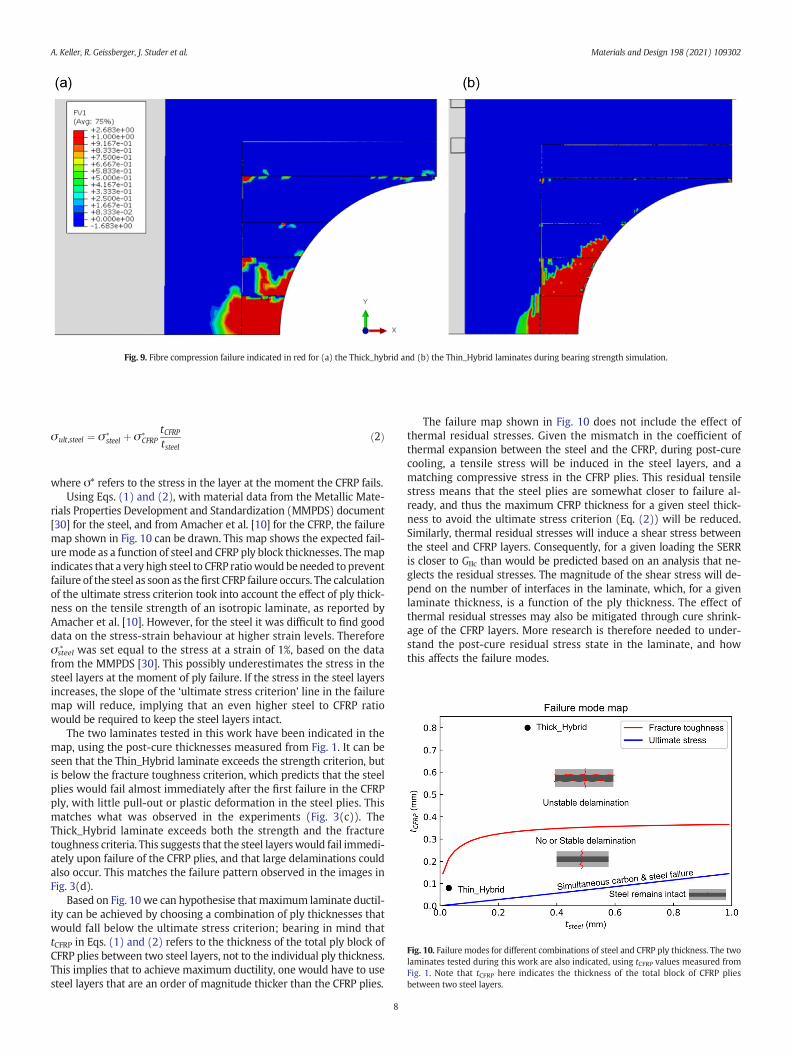
Fig. 10. Failure modes for different combinations of steel and CFRP ply thickness. The twolaminates tested during this work are also indicated, using tCFRP values measured fromFig. 1. Note that tCFRP here indicates the thickness of the total block of CFRP pliesbetween two steel layers.
Fig. 9. Fibre compression failure indicated in red for (a) the Thick_hybrid and (b) the Thin_Hybrid laminates during bearing strength simulation.
A. Keller, R. Geissberger, J. Studer et al. Materials and Design 198 (2021) 109302
σult,steel ¼ σ ∗steel þ σ ∗
CFRPtCFRPtsteel
ð2Þ
where σ* refers to the stress in the layer at the moment the CFRP fails.Using Eqs. (1) and (2), with material data from the Metallic Mate-
rials Properties Development and Standardization (MMPDS) document[30] for the steel, and from Amacher et al. [10] for the CFRP, the failuremap shown in Fig. 10 can be drawn. This map shows the expected fail-uremode as a function of steel and CFRP ply block thicknesses. Themapindicates that a very high steel to CFRP ratiowould beneeded to preventfailure of the steel as soon as thefirst CFRP failure occurs. The calculationof the ultimate stress criterion took into account the effect of ply thick-ness on the tensile strength of an isotropic laminate, as reported byAmacher et al. [10]. However, for the steel it was difficult to find gooddata on the stress-strain behaviour at higher strain levels. Thereforeσsteel
∗ was set equal to the stress at a strain of 1%, based on the datafrom the MMPDS [30]. This possibly underestimates the stress in thesteel layers at the moment of ply failure. If the stress in the steel layersincreases, the slope of the ‘ultimate stress criterion’ line in the failuremap will reduce, implying that an even higher steel to CFRP ratiowould be required to keep the steel layers intact.
The two laminates tested in this work have been indicated in themap, using the post-cure thicknesses measured from Fig. 1. It can beseen that the Thin_Hybrid laminate exceeds the strength criterion, butis below the fracture toughness criterion, which predicts that the steelplies would fail almost immediately after the first failure in the CFRPply, with little pull-out or plastic deformation in the steel plies. Thismatches what was observed in the experiments (Fig. 3(c)). TheThick_Hybrid laminate exceeds both the strength and the fracturetoughness criteria. This suggests that the steel layerswould fail immedi-ately upon failure of the CFRP plies, and that large delaminations couldalso occur. This matches the failure pattern observed in the images inFig. 3(d).
Based on Fig. 10 we can hypothesise that maximum laminate ductil-ity can be achieved by choosing a combination of ply thicknesses thatwould fall below the ultimate stress criterion; bearing in mind thattCFRP in Eqs. (1) and (2) refers to the thickness of the total ply block ofCFRP plies between two steel layers, not to the individual ply thickness.This implies that to achieve maximum ductility, one would have to usesteel layers that are an order of magnitude thicker than the CFRP plies.
8
The failure map shown in Fig. 10 does not include the effect ofthermal residual stresses. Given the mismatch in the coefficient ofthermal expansion between the steel and the CFRP, during post-curecooling, a tensile stress will be induced in the steel layers, and amatching compressive stress in the CFRP plies. This residual tensilestress means that the steel plies are somewhat closer to failure al-ready, and thus the maximum CFRP thickness for a given steel thick-ness to avoid the ultimate stress criterion (Eq. (2)) will be reduced.Similarly, thermal residual stresses will induce a shear stress betweenthe steel and CFRP layers. Consequently, for a given loading the SERRis closer to GIIc than would be predicted based on an analysis that ne-glects the residual stresses. The magnitude of the shear stress will de-pend on the number of interfaces in the laminate, which, for a givenlaminate thickness, is a function of the ply thickness. The effect ofthermal residual stresses may also be mitigated through cure shrink-age of the CFRP layers. More research is therefore needed to under-stand the post-cure residual stress state in the laminate, and howthis affects the failure modes.

A. Keller, R. Geissberger, J. Studer et al. Materials and Design 198 (2021) 109302
Concluding this section, the analysis suggests that, unless one usesvery high steel to CFRP thickness ratios, it is not possible to make opti-mal use of the steel's ductility, as the steel layers will fail almost imme-diately when the CFRP layers fail. However, laminate failure strain andenergy absorption can be improved by allowing delamination tooccur, which implies selecting a combination of thicknesses close to orabove the unstable delamination criterion. For example, from Fig. 10we can hypothesise that in a thin-ply layup with 8 or 12 ply quasi-isotropic blocks between the steel foils, delamination would occur, asthe laminate would be above the delamination criterion. This wouldlikely reduce the notch sensitivity of the laminate, allowing more opti-mal use of the increased strength of the thin-ply material. Apart fromadjusting the ply thickness ratio, one can also influence interfacestrength by changing the surface treatment of the steel layers, whichwill affect the adhesion between the steel and the epoxy, and thereforethe value of GIIc.
6. Conclusions
The open hole tensile and bearing strength of Thin_CFRP andThick_CFRP were successfully increased by steel foil hybridisation.Hybridisation increased the Thin_CFRP OHT strength by 63%, allowinga significant decrease in thickness to achieve the same strength aswith-out steel foils. Furthermore, the Thin_Hybrid can be almost 20% thinnerthan the Thick_CFRP to achieve the same OHT strength. The laminatethickness is likely driven by the strength needed around the hole. There-fore, by applying the steel foils locally around the hole an overall thinnerlaminate can be used.
The smaller the ratio of reinforced to unreinforced area, the largerthe weight savings, with a maximum of 20%, corresponding to the re-duction in thickness. Hence, a local steel foil substitution with 20% ofthe total laminate area leads to a lighter and thinner part in comparisonto a pure CFRP part with the same strength.
The use of steel foils avoids the need to add more carbon fibreplies in areas to be reinforced, which would require additionaldebulking cycles, as well as introduce load path eccentricity. Thisnovel approach is especially interesting for thin-ply materials toovercome the high notch sensitivity while keeping the general ad-vantages, i.e. high tensile and compression strength, with the com-promise of reduced mass specific mechanical performance. Theonset bearing strength for the Thick_Hybrid was even higher thanthe ultimate strength of both CFRP composites, with similar valuesfor the specific bearing strength.
The developed finite element models can provide good predic-tions of the OHT strength, as well as identify which failure modeswill occur. In future research they can therefore be used to optimiselaminate design and to tune the ply thickness and layup to obtain de-sirable failure behaviour, e.g. to promote delaminations to reducenotch sensitivity. They can also be utilised to optimise the specificstrength of the hybrid laminates, and to understand whether thereare trade-offs between ultimate strain, notch sensitivity andunnotched tensile strength. These models could also be used to fur-ther study the stress distribution in the transition zones betweenmetal and CFRP layers, which can affect delamination initiation. Toenable local reinforcement designs on an industrial level, further in-vestigations are necessary to understand what radius around a holeneeds to be reinforced in order to obtain the increased open holeand bearing strengths.
CRediT authorship contribution statement
A. Keller: Investigation, Writing - review & editing. R. Geissberger:Investigation, Formal analysis. J. Studer: Methodology. F. Leone:Investigation. D. Stefaniak: Resources, Methodology. J.A. Pascoe: Visu-alization,Writing - review & editing. C. Dransfeld: Supervision,Writing
9
- review & editing, Funding acquisition. K. Masania: Conceptualization,Supervision, Writing - original draft, Writing - review & editing.
Declaration of Competing Interest
The authors declare no competing interests.
Acknowledgments
This work was carried out within the collaborative research projectCost Effective Reinforcement of Fasteners in Aerospace Composites(CERFAC) funded by the European Commission, grant agreement no.266026, within the Seventh Framework Programme. The authors thankC. Gosrani and W. Woigk for helpful comments and feedback.
References
[1] C. Soutis, Fibre reinforced composites in aircraft construction, Prog. Aerosp. Sci. 41(2) (2005) 143–151.
[2] M.K. Hagnell, M. Åkermo, A composite cost model for the aeronautical industry:methodology and case study, Compos. Part B 79 (2015) 254–261.
[3] J. Studer, C. Dransfeld, K. Masania, An analytical model for B-stage joining and co-curing of carbon fibre epoxy composites, Compos. A: Appl. Sci. Manuf. 87 (2016)282–289.
[4] A. Fink, P.P. Camanho, J.M. Andras, E. Pfeiffer, A. Obst, Hybrid CFRP/titanium boltedjoints: performance assessment and application to a spacecraft payload adaptor,Compos. Sci. Technol. 70 (2) (2009) 305–317.
[5] B. Kolesnikov, L. Herbeck, A. Fink, CFRP/titanium hybridmaterial for improving com-posite bolted joints, Compos. Struct. 83 (4) (2008) 368–380.
[6] J. Studer, A. Keller, F. Leone, D. Stefaniak, C. Dransfeld, K. Masania, Local reinforce-ment of aerospace structures using co-curing RTM of metal foil hybrid composites,Prod. Eng. (2018) 1–7.
[7] K. Masania, R. Geissberger, F. Leone, J. Studer, D. Stefaniak, C. Dransfeld, Steel foil re-inforced composites: experimental and numerical study of strength, plasticity andply size effects, European Conf. Compos. Mater. (2014).
[8] M. Sung, J. Jang, V.L. Tran, S.-T. Hong, W.-R. Yu, Increased breaking strain of carbonfiber-reinforced plastic and steel hybrid laminate composites, Compos. Struct. 235(2020) 111768.
[9] E. Petersen, J. Koord, O. Völkerink, D. Stefaniak, C. Hühne, Experimental and numer-ical investigation of the transition zone of locally steel-reinforced joining areasunder combined tension–bending loading, J. Compos. Mater. 0 (0) (2019)0021998319893729.
[10] R. Amacher, J. Cugnoni, J. Botsis, L. Sorensen, W. Smith, C. Dransfeld, Thin ply com-posites: experimental characterization and modeling of size-effects, Compos. Sci.Technol. 101 (2014) 121–132.
[11] C. Furtado, A. Arteiro, G. Catalanotti, J. Xavier, P. Camanho, Selective ply-levelhybridisation for improved notched response of composite laminates, Compos.Struct. 145 (2016) 1–14.
[12] C. Huang, S. Ju, M. He, Q. Zheng, Y. He, J. Xiao, J. Zhang, D. Jiang, Identification of fail-ure modes of composite thin-ply laminates containing circular hole under tensionby acoustic emission signals, Compos. Struct. 206 (2018) 70–79.
[13] A. Arteiro, G. Catalanotti, J. Xavier, P. Linde, P. Camanho, A strategy to improve thestructural performance of non-crimp fabric thin-ply laminates, Compos. Struct.188 (2018) 438–449.
[14] J. Cugnoni, R. Amacher, S. Kohler, J. Brunner, E. Kramer, C. Dransfeld, W. Smith, K.Scobbie, L. Sorensen, J. Botsis, Towards aerospace grade thin-ply composites: effectof ply thickness, fibre, matrix and interlayer toughening on strength and damagetolerance, Compos. Sci. Technol. 168 (2018) 467–477.
[15] J. Galos, Thin-ply composite laminates: a review, Compos. Struct. 236 (2020)111920.
[16] B. Bosbach, C. Ohle, B. Fiedler, Structural health monitoring of fibre metal laminatesunder mode I and II loading, Compos. A: Appl. Sci. Manuf. 107 (2018) 471–478.
[17] B. Kötter, J. Karsten, J. Körbelin, B. Fiedler, CFRP thin-ply fibremetal laminates: influ-ences of ply thickness andmetal layers on open hole tension and compression prop-erties, Materials 13 (4) (2020) 910.
[18] A. Fink, P. Camanho, J. Andrés, E. Pfeiffer, A. Obst, Hybrid CFRP/titanium boltedjoints: performance assessment and application to a spacecraft payload adaptor,Compos. Sci. Technol. 70 (2) (2010) 305–317.
[19] E. Petersen, J. Koord, O. Völkerink, D. Stefaniak, C. Hühne, Experimental and numer-ical investigation of the transition zone of locally steel-reinforced joining areasunder combined tension–bending loading, J. Compos. Mater. 54 (17) (2020)2339–2352.
[20] E. Petersen, D. Stefaniak, C. Hühne, Experimental investigation of load carryingmechanisms and failure phenomena in the transition zone of locally metal rein-forced joining areas, Compos. Struct. 182 (2017) 79–90.
[21] R. Geissberger, J. Maldonado, N. Bahamonde, A. Keller, C. Dransfeld, K. Masania, Rhe-ological modelling of thermoset composite processing, Compos. Part B 124 (2017)182–189.

A. Keller, R. Geissberger, J. Studer et al. Materials and Design 198 (2021) 109302
[22] K. Blohowiak, R. Anderson, W. Grace, J. Grob, D. Fry, Development of new thin adhe-sive systems and test methods for TiGr laminates, SAMPE conference, 2008 , LongBeach, USA.
[23] Z. Hashin, Failure criteria for unidirectional fiber composites, J. Appl. Mech. 47 (2)(1980) 329–334.
[24] G. Johnson, W. Cook, A constitutive model and data for metals subjected to largestrains, strain rates, and high pressures, Proceedings of the 7th International Sympo-sium On Ballistics, 1983.
[25] M. Ljunkrantz, Design of a CFRP-to-Steel Joint for a Bus Engine Mount and Experi-mental Testing of Joint Relaxation, 2012.
[26] Y. Xiao, T. Ishikawa, Bearing strength and failure behavior of bolted composite joints(part II: modeling and simulation), Compos. Sci. Technol. 65 (7–8) (2005)1032–1043.
10
[27] J. Rehra, B. Hannemann, S. Schmeer, J. Hausmann, U.P. Breuer, Approach for an ana-lytical description of the failure evolution of continuous steel and carbon fiber hy-brid composites, Adv. Eng. Mater. 21 (6) (2019) 1800565.
[28] G. Czél, M. Wisnom, Demonstration of pseudo-ductility in high performance glass/epoxy composites by hybridisation with thin-ply carbon prepreg, Compos. A:Appl. Sci. Manuf. 52 (2013) 23–30.
[29] G. Czél, M. Jalalvand, M.R. Wisnom, Design and characterisation of advancedpseudo-ductile unidirectional thin-ply carbon/epoxy–glass/epoxy hybrid compos-ites, Compos. Struct. 143 (2016) 362–370.
[30] Federal Aviation Administration, Metallic Materials Properties Development andStandardization (MMPDS), U.S. Department of Transportation, 2003.