experimental and fea analysis of different grade oil
TRANSCRIPT

e-ISSN: 2582-5208 International Research Journal of Modernization in Engineering Technology and Science Volume:02/Issue:08/August-2020 Impact Factor- 5.354 www.irjmets.com
www.irjmets.com @International Research Journal of Modernization in Engineering, Technology and Science
[38]
EXPERIMENTAL AND FEA ANALYSIS OF DIFFERENT GRADE OIL
DAMPING USING SHOCK ABSORBER
Pushkar P. Sangale *1, Prof. Dr. Kashinath Munde*2
*1PG Student, Dept. of Mechanical Engineering, ABMSP’s APCOER, Pune, Maharashtra, India.
*2ME Coordinator, Dept. of Mechanical Engineering, ABMSP’s APCOER, Pune, Maharashtra, India.
ABSTRACT
A system of mechanical linkages, springs, damper that is used to connect the wheels to the chassis is
known as suspension system. It has usually done two works-controlling the vehicle’s handling and
braking for safety and keeping the passengers comfortable from bumps, vibrations. There are many types
of shock absorbers available in market /industry different kinds of techniques are there to reduce
shocking effect on running vehicles and to make a ride comfortable. This work includes, design and
development of test setup of damper operate as a passive damping system within certain performance
parameters depending on the off-state characteristics of the fluid inside the cylinder damper in CATIA
software. Initially three different grades low, medium and high-grade oil are selected to study the
developed experimental setup experimentally while in analysis ANSYS software is used to determine
elongation with different grade oil along with damping coefficient. After loading of each oil sample, we
will take reading of test specimen to find out natural frequency of conventional damper. Experimental
testing will be performed with help of FFT analyzer and impact hammer test.
KEYWORDS: Oil Damper, Oil Sample, FEA, FFT analyzer.
I. INTRODUCTION
A Mechanical framework made by numerous parts which are having movement and vibration. Here and
there movements and vibrations can be valuable however inordinate vibration makes distress
individuals, damage to machines and structures and wear of machine parts, for example, course and
apparatuses. The drivers of vehicles during are presented to vibration due the unequal pivoting portions
of the machines or by the street surface lopsidedness. The most concerning issue to traveler is that they
are presented to vibrations in a recurrence go from very nearly 0 to 20 Hz. This sort of distress makes
that the driver and travelers lose fixation, get worn-out right-on time and following quite a long while it
can effects affect their wellbeing. Most current vehicles are outfitted with shock absorbers to hose the
vibrations caused to the vehicle body when going over lopsided streets. They structure a basic piece of
the vehicle suspension framework and helps in restricting body development of the vehicle, settling the
ride and tires just as cutoff the damage caused to the vehicle skeleton. Another significant capacity of the
shock absorber is to keep the vehicle tire in contact with the ground consistently, even on a rough street.
Remembering these basic capacities, stresses created in the shock absorber and the subsequent
redirection are the two most significant parameters to be dealt with while planning a shock absorber for
any vehicle. As a significant gadget utilized in suspension frameworks of current vehicles, the shock
absorber is mounted between auto scaffold and casing for damping the vibration brought about by
lopsided street to direct incautious load. In this manner, the damping execution of the shock absorber is
of significance to running perfection, working unfaltering quality and through limit of vehicles. With
requesting necessities for security and solace of driving vehicle, examine on the shock absorber have
increased increasingly more consideration, including its high recurrence execution, tests for damping
trademark, temperature control, commotion issue, and so forth.
II. LITERATURE SURVEY
Dong Guan et al. [1] In this paper it presents the dynamic execution of a twin-tube shock absorber is
explored by experimental and simulation. Dynamic determination and damping coefficients are explored
under duplicate conditions. Test study show damping power failure is profoundly speed related, it
effectively happens at stroke end, particularly the pressure end when velocity is greater than 0.31 m/s.

e-ISSN: 2582-5208 International Research Journal of Modernization in Engineering Technology and Science Volume:02/Issue:08/August-2020 Impact Factor- 5.354 www.irjmets.com
www.irjmets.com @International Research Journal of Modernization in Engineering, Technology and Science
[39]
Damping power at bounce back stroke end may likewise diminish strongly at high speeds velocity is
greater than 0.75 m/s. Damping power failure is brought about by dormancy cavitation of water driven
oil, and the hypothetical damping power model, which considers cavitation impact, is additionally
introduced and investigated inside and out to decipher such speed related cavitation attributes. The
greatest powerful firmness happens at the most extreme speed focuses, while diminishes to 0 at each
stroke end. The most extreme dynamic damping coefficient happens under a particular speed during
bounce back stroke, it diminishes at the different sides of such speed.
Yang Jianmincet al. [2]In this article it presents shock absorber with coulomb–liquid damping through
coupling oil, wire dressing, spring by quick strategies is intended for reinforcement of electronic-data
hardware in out rageousvibration and effect. In light of this, the non-straight powerful model for
weakening vibration method of the shock absorber is introduced by examining coupling physical
component of liquid and Coulomb grating and different components for planning the shock absorber with
high legitimacy. As the model outcomes concur well with the test information, it tends to be utilized for
building plan. In the resonance band, the shock absorber shows a trait of developing damping. It makes
the outright speeding up transmissibility approach to one. It is concluded that coulomb– liquid damping
shock absorber has a decent unique exhibition vibration control and controllable structure capacity, for
instance, we can plan the shock absorber with non-resonance peak and low-frequency constriction band.
In low-frequency weakening band, the framework shows an outstanding damping power along with the
oil damping power which is interrelated with speed is little.
I.V. Ryabovaet al. [3]In this research it presents the analytical confirmation of the nearness of two
inefficient areas in vehicle suspension impacting cycle in straight shock absorber work. It is determined
based on investigation of the element’s conditions for the straight single-bolster single-mass vibrating
framework with fixed flexible and damping qualities at symphonious kinematic unsettling influence.
Thereunder the conditions for estimation of the compelling shock absorber work proportion for different
kinds of damping qualities are resolved. The charts of the powerful shock absorber work proportion on
the general frequency of the unsettling influence and the relative damping factor are executed. The
assessment of vehicle suspension proficiency dependent on the estimations of inefficient power beat
proportion for known effective control calculations of flexible damping normal for pneumatic shock
absorber. In this way, it is scientifically demonstrated the presence of two inefficient work areas of shock
absorber in wavering pattern of vehicle suspension on the case of single-mass single-support vibrating
framework with unregulated versatile and damping attributes. The consequences of trial reads for
different sorts of vehicles suspensions are affirmed also, show that the impact of the straight water
powered damper is coordinated to speeding up and sufficiency of the sprung mass relocation of the
vehicle. Accessibility of inefficient work zones of shock absorber in wavering cycle of vehicles suspension
requires expanding its damping properties in these regions based on present day techniques for the
attributes control.
Yang Pinget al. [4] In this paper it presents study on microstructure oil-damping shock absorber for the
security of electronic packaging segments in vibration-influence situations. The nonlinearity of the oil
consistency, the oil stream qualities, and the coupling between the oil and the physical structure were
remembered for a numerical model of the oil-damping shock absorber to constrict vibrations. The
consequences of multi-parameter-coupled dynamic tests show that the scientific model precisely
recreates the genuine physical arrangement of the oil damping shock absorber. The model could be
utilized for building plans of vibration-influence seclusion of electronic-bundling segments. A scientific
model of the dynamic conduct of the shock absorber was created to depict all the material science in the
shock absorber. The numerical outcomes concur well with the exploratory information, so the model can
be utilized for the structure of building framework.
Ninbo Liaoet al. [5]In this journal it presents to give a methodical examination to plan or assessment of
a shock absorber for assurance of electronic gear framework in cruel vibration-impact condition. A tale
Si-oil coupling damping shock absorber is structured and made through coupling Si-oil, elastic ball and
spring by cunning strategies. A nonlinear unique model for the shock absorber is introduced by breaking
e-ISSN: 2582-5208 International Research Journal of Modernization in Engineering Technology and Science Volume:02/Issue:08/August-2020 Impact Factor- 5.354 www.irjmets.com
www.irjmets.com @International Research Journal of Modernization in Engineering, Technology and Science
[40]
down the inside liquid powerful marvel as for the model. An epic oil coupling shock absorber was
researched for support of electronic in framework. It has a great powerful execution and controllable plan
capacity. A numerical model of the dynamic conduct of the shock absorber has been created so as to
depict the attributes happening inside the shock absorber, the numerical reenactment shows the model
can mimic the real shock absorber in rough. It shows plentifulness and frequency of excitation, just as oil
consistency, proportion of damping territory are the key factor to guarantee the exhibition of the shock
absorber.
Shoukun Wanget al. [6]In this paper it presents the pressurized water driven shaking table has been
produced for damping trademark probes shock absorbers. The damping qualities and relating probes the
twofold cylinder water driven shock absorber are investigated right off the bat, and its damping power
model is likewise constructed. An open-closed loop ILC strategy is proposed to beat the asymmetry,
vulnerability and nonlinearity of the water powered control framework. At that point framework rule and
real parts of the shaking table are depicted, and the model of pressure driven actuator, formed of servo
valve controlled deviated chamber with damping load, is investigated. Created by such electro-pressure
driven control innovation, this using pressurized water driven shaking table has been applied to the
damping trademark examination of a sequential of shock absorbers in a vehicle get together plant of
Beijing, and has accomplished perfect execution, with 50 kN greatest load power, 0.1 m vibration
abundancy, 5 Hz greatest vibration frequency, 1 mm position control exactness (sine vibration with 0.05
m abundancy and 2 Hz frequency) and 24 h steady span.
III. PROBLEM STATEMENT
The shock absorber of the vehicle are going failure in many cases now we concentrate on a load which is
acted maximum in the damper spring during the sudden impact of the vehicle in the un even roads. In
that conditions load acting in the spring are damped load from the tire weight of the vehicle and person
who riding the vehicle.
IV. OBJECTIVES 1. Design and development of test set-up of oil damper using shock- absorber in CATIA software.
2. Modal analysis to determine natural frequency, elongation length for different grade oil in ANSYS
software.
3. Damping will be calculated based on input and output acceleration value using FFT technique.
4. Varity of grade (low, medium and high grade) of fluid for parametric study of viscosity.
5. Validation of results with FFT technique and numerical results.
V. METHODOLOGY Initially research paper relevant to the topic is gathered and after going through research papers,
shock absorber setup is examined.
A 3-D CAD model will be prepared by studying the conventional design of mini setup for oil damper
setup
Prepared 3-D model will be transferred to ANSYS software and proper meshing will be created on the
model for further analysis.
For determining the mode shape, natural frequency along with elongation with different grade oil
modal analysis with respective damping coefficient will be provided and performed in ANSYS
software.
A prototype of the model will be manufactured.
FFT analysis will be performed on the oil damper setup to determine acceleration at respective grade
oil.
Validation of experimental and numerical results.

e-ISSN: 2582-5208 International Research Journal of Modernization in Engineering Technology and Science Volume:02/Issue:08/August-2020 Impact Factor- 5.354 www.irjmets.com
www.irjmets.com @International Research Journal of Modernization in Engineering, Technology and Science
[41]
VI. SCHEMATIC LAYOUT
Fig-1: Schematic layout of experimental setup
Fig-2: CATIA model of oil damper set-up
Three-dimensional model of oil damper set-upwas making in Catia V5 R20 software.
Fig-3: Drafting of oil damper set-up
e-ISSN: 2582-5208 International Research Journal of Modernization in Engineering Technology and Science Volume:02/Issue:08/August-2020 Impact Factor- 5.354 www.irjmets.com
www.irjmets.com @International Research Journal of Modernization in Engineering, Technology and Science
[42]
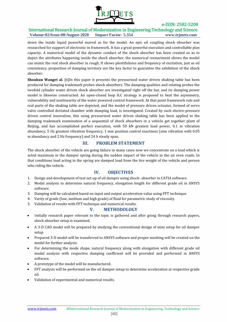
VII. FINITE ELEMENT ANALYSIS OF OIL DAMPERSET-ANSYS
1. Geometry
Fig-4: Geometry imported in ANSYS
ANSYS Meshing is a general-purpose, intelligent, automated high-performance product. It produces the
most appropriate mesh for accurate, efficient Multiphysics solutions. In ANSYS after importing geometry
in module meshing is performed also known as discretization process. In meshing whole component is
breakdown or discretized into small elements to solve finite element equation at nodes. In present
tetrahedral mesh is used for analysis. A mesh well suited for a specific analysis can be generated with a
single mouse click for all parts in a model.
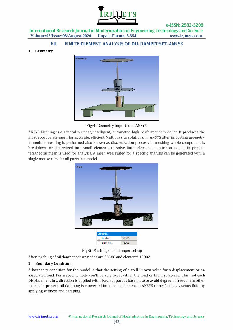
Fig-5: Meshing of oil damper set-up
After meshing of oil damper set-up nodes are 38386 and elements 18002.
2. Boundary Condition
A boundary condition for the model is that the setting of a well-known value for a displacement or an
associated load. For a specific node you'll be able to set either the load or the displacement but not each
Displacement in z direction is applied with fixed support at base plate to avoid degree of freedom in other
to axis. In present oil damping is converted into spring element in ANSYS to perform as viscous fluid by
applying stiffness and damping.

e-ISSN: 2582-5208 International Research Journal of Modernization in Engineering Technology and Science Volume:02/Issue:08/August-2020 Impact Factor- 5.354 www.irjmets.com
www.irjmets.com @International Research Journal of Modernization in Engineering, Technology and Science
[43]
Fig-6: boundary condition of oil damper set-up
3. Results
In finite element method the total deformation and directional deformation are general terms
irrespective of software being used. Directional deformation may be place because the displacement of
the system in a very particular axis or user defined direction. Total deformation is that the vector sum of
all directional displacements of the systems.
Fig-7: Mode shape 1
Natural frequency of oil damper set-up at mode shape 1 was 109.39 Hz
Fig-8: Mode shape 4

e-ISSN: 2582-5208 International Research Journal of Modernization in Engineering Technology and Science Volume:02/Issue:08/August-2020 Impact Factor- 5.354 www.irjmets.com
www.irjmets.com @International Research Journal of Modernization in Engineering, Technology and Science
[44]
Table-1: Tabular representation of the mode shapes with respective frequency.
Determination of elastic force and elongation over applied damping coefficient
Fig-9: Result for low grade oil
It is observed that using damping coefficient as 0.2 elastic force is around 16 kN with elongation of 32
mm.
Variation of damping coefficient to 0.4 (Medium grade oil) Ns/mm
Fig-10:.Boundary condition of oil damper set-up for medium grade oil
AT MODE 1
e-ISSN: 2582-5208 International Research Journal of Modernization in Engineering Technology and Science Volume:02/Issue:08/August-2020 Impact Factor- 5.354 www.irjmets.com
www.irjmets.com @International Research Journal of Modernization in Engineering, Technology and Science
[45]
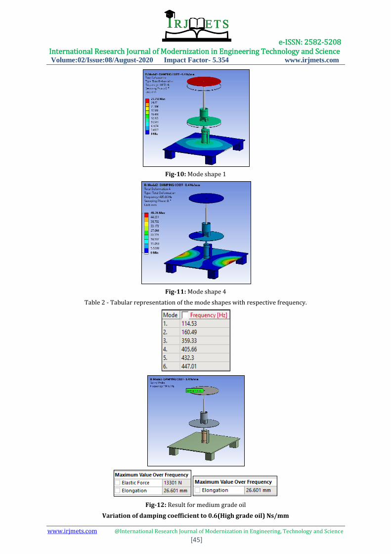
Fig-10: Mode shape 1
Fig-11: Mode shape 4
Table 2 - Tabular representation of the mode shapes with respective frequency.
Fig-12: Result for medium grade oil
Variation of damping coefficient to 0.6(High grade oil) Ns/mm

e-ISSN: 2582-5208 International Research Journal of Modernization in Engineering Technology and Science Volume:02/Issue:08/August-2020 Impact Factor- 5.354 www.irjmets.com
www.irjmets.com @International Research Journal of Modernization in Engineering, Technology and Science
[46]
Fig-13: Boundary condition of oil damper set-up for medium grade oil
Fig-14: Mode shape 1
Fig-15: Mode shape 4
Table-2: Tabular representation of the mode shapes with respective frequency.
e-ISSN: 2582-5208 International Research Journal of Modernization in Engineering Technology and Science Volume:02/Issue:08/August-2020 Impact Factor- 5.354 www.irjmets.com
www.irjmets.com @International Research Journal of Modernization in Engineering, Technology and Science
[47]
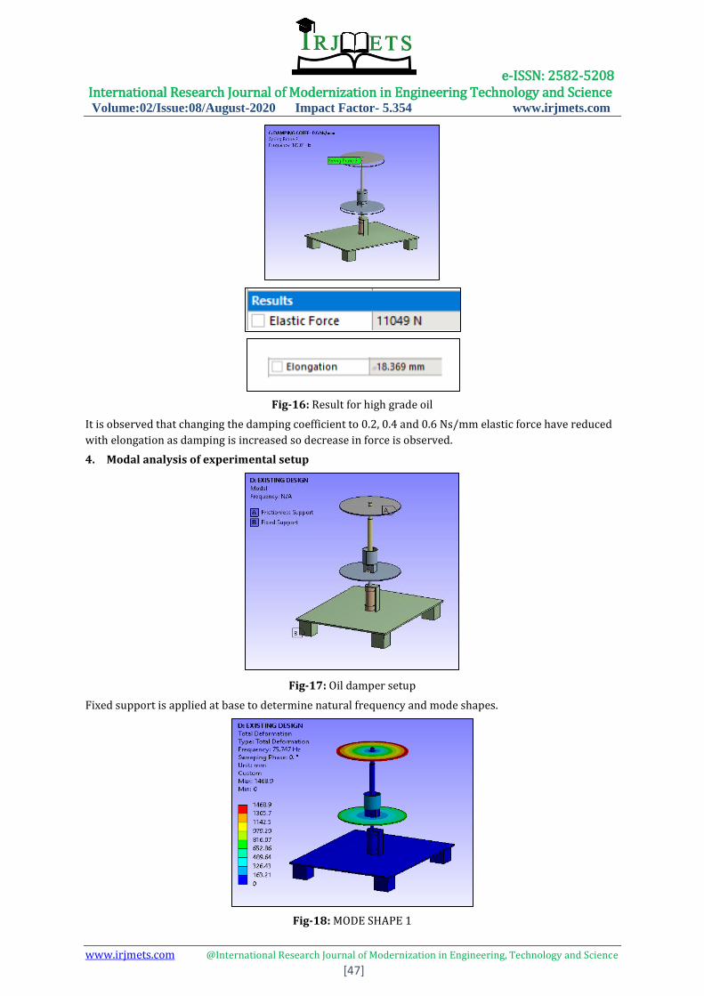
Fig-16: Result for high grade oil
It is observed that changing the damping coefficient to 0.2, 0.4 and 0.6 Ns/mm elastic force have reduced
with elongation as damping is increased so decrease in force is observed.
4. Modal analysis of experimental setup
Fig-17: Oil damper setup
Fixed support is applied at base to determine natural frequency and mode shapes.
Fig-18: MODE SHAPE 1

e-ISSN: 2582-5208 International Research Journal of Modernization in Engineering Technology and Science Volume:02/Issue:08/August-2020 Impact Factor- 5.354 www.irjmets.com
www.irjmets.com @International Research Journal of Modernization in Engineering, Technology and Science
[48]
Fig-19: MODE SHAPE 3
Table-3: Tabular data of natural frequency
VIII. EXPERIMENTAL TESTING 1) Fast Fourier Transform
The experimental validation is done by using FFT (Fast Fourier Transform) analyzer. The FFT spectrum
analyzer samples the input signal, computes the magnitude of its sine and cosine components, and
displays the spectrum of these measured frequency components. The advantage of this technique is its
speed. Because FFT spectrum analyzers measure all frequency components at the same time, the
technique offers the possibility of being hundreds of times faster than traditional analog spectrum
analyzers.
2) Impact Hammer Test
Impact excitation is one of the most common methods used for experimental modal testing. Hammer
impacts produce a broad banded excitation signal ideal for modal testing with a minimal amount of
equipment and set up. Furthermore, it is versatile, mobile and produces reliable results. A phenomenon
commonly encountered during impact testing is the so called "double hit". The "double hit" applies two
impulses to the structure, one initially and one time delayed. Both the temporal and spectral
characteristics of the "double hit" input and output are significantly different than a "single hit". The input
force spectrum for the "double hit" no longer has the wide band constant type characteristics of a single
hit. The relationship of the system's parameters with respect to data capture requirements is evaluated.
The effects of exponential windowing are developed to examine the effects on the estimated spectra and
modal parameters. Finally, the "double hit" phenomena is examined by combining the results from the
single degree-of-freedom system excited by two impulses, one of which is time delayed. The results from
these related studies are combined to provide insight into data acquisition guidelines for structural
impact testing.

e-ISSN: 2582-5208 International Research Journal of Modernization in Engineering Technology and Science Volume:02/Issue:08/August-2020 Impact Factor- 5.354 www.irjmets.com
www.irjmets.com @International Research Journal of Modernization in Engineering, Technology and Science
[49]
Fig-20: Block diagram of FFT
Fig-21: Experimental set up
Fig-22: Experimental set up testing
3) Experimental Procedure
Initially fixture is designed according to existing boundary condition as per FEA results.
FFT consists of impact hammer, accelerometer, data acquisition system in which each supply is applied to
DAS and laptop with DEWSOFT software to view FFT plot.
Accelerometer is mounted at edge as per high deformation observed in FEA results along with initial
impact of hammer is placed for certain excitation to determine frequency of respective mode shapes.
After impact FFT plot are observed on laptop and comparison of FEA and experimental results are
analyzed.

e-ISSN: 2582-5208 International Research Journal of Modernization in Engineering Technology and Science Volume:02/Issue:08/August-2020 Impact Factor- 5.354 www.irjmets.com
www.irjmets.com @International Research Journal of Modernization in Engineering, Technology and Science
[50]
Fig-23: FFT plot of oil damper setup
Table-4: Comparison of oil damper setup FEA and FFT results
Experimental Procedure
After completion of oil damper setup testing reading was taken.
first, we had applied constant pressure of 2 Bar to pneumatic cylinder of dimension 25*50 on which
damper was mounted.
For applying constant force on oil damper Solenoid valve and Arduino Uno circuit was used.
Then accelerometer was placed at output section of pneumatic cylinder on which Oil damper was
mounted and then reading of acceleration was taken.
after that accelerometer shifted to the output section of Oil damper plate and reading of acceleration
was taken.
Fig-24: FFT plot of acceleration of input excitation of pneumatic exciter
e-ISSN: 2582-5208 International Research Journal of Modernization in Engineering Technology and Science Volume:02/Issue:08/August-2020 Impact Factor- 5.354 www.irjmets.com
www.irjmets.com @International Research Journal of Modernization in Engineering, Technology and Science
[51]
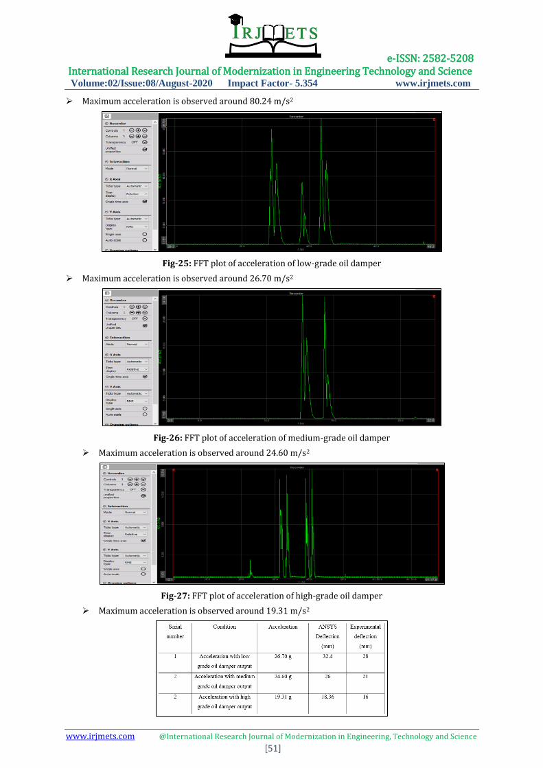
Maximum acceleration is observed around 80.24 m/s2
Fig-25: FFT plot of acceleration of low-grade oil damper
Maximum acceleration is observed around 26.70 m/s2
Fig-26: FFT plot of acceleration of medium-grade oil damper
Maximum acceleration is observed around 24.60 m/s2
Fig-27: FFT plot of acceleration of high-grade oil damper
Maximum acceleration is observed around 19.31 m/s2
e-ISSN: 2582-5208 International Research Journal of Modernization in Engineering Technology and Science Volume:02/Issue:08/August-2020 Impact Factor- 5.354 www.irjmets.com
www.irjmets.com @International Research Journal of Modernization in Engineering, Technology and Science
[52]
IX. CONCLUSION
In present research oil damping characteristics of different grade oil (low, medium and
high) are selected along with design of experimental setup to measure acceleration of each
grade.
Initially in FEA analysis damping values are varied as per damping to obtain elongation and
force. It is observed that increase in damping coefficient decreases elongation along with
elastic force.
Modal analysis of experimental setup is performed to determine natural frequency along
with respective mode shape and experimental FFT technique is utilized for comparison of
result. It is seen that natural frequency obtained by both FEA and FFT are similar in range.
During experimental testing of varying grades of oil in damper it is observed that
acceleration values tend tends to decrease with increase in viscosity of oil.
Input excitation is around 80 m/s2, along with low, medium and high-grade oil peak
acceleration is observed around 26.70, 24.60 and 19.31 m/s2 respectively.
X. REFERENCES [1] Dong Guan , Xingjian Jing , Hui Shen a, Li Jing a, Junjie Gong "Test and simulation the failure
characteristics of twin tube shock absorber." Mechanical Systems and Signal Processing 122 (2019)
707–719.
[2] Yang Pinga,b, Tan Yonghongb, Yang Jianminc, Sun Ninb."Measurement, simulation on dynamic
characteristics of a wire gauze–fluid damping shock absorber " Mechanical Systems and Signal
Processing 20 (2006) 745–756.
[3] A.V. Pozdeev "Efficiency of Shock Absorber in Vehicle Suspension" by I.V. Ryabova, V.V. Novikova,
Procedia Engineering 150 ( 2016 ) 354 – 362.
[4] YANG Ping "Mechanical Characteristics of Oil-Damping Shock Absorber for Protection of Electronic-
Packaging Components" Tsinghua Science And Technology ISSN 1007-0214 14/23 pp216-
220Volume 10, Number 2, April 2005.
[5] Ping Yang ,Ninbo Liao, Jianbo Yang "Design, test and modelling evaluation approach of a novel Si-oil
shock absorber for protection of electronic equipment in moving vehicles" Mechanism and Machine
Theory 43 (2008) 18–32
[6] Pinjarla.Poornamohan1, Lakshmana Kishore. T, "Design and analysis of a shock absorber" , IJRET:
International Journal of Research in Engineering and Technology ISSN: 2319-1163
[7] Sitangshu Chatterjee, Subhas Nandy, "Optimization of a shock absorber using Finite Element
Analysis", International Journal of Science, Engineering and Technology Research(IJSETR) Volume 7,
Issue 8, August 2018, ISSN: 2278 -7798
[8] D.I. Narkhede, R. Sinha, Behavior of nonlinear fluid viscous dampers for control of shock vibrations, J.
Sound Vib. 333 (2014) 80–98.
[9] Z. Lu, Z. Wang, Y. Zhou, X. Lu, Nonlinear dissipative devices in structural vibration control: a review, J.
Sound Vib. 423 (2018) 18–49.
[10] Z.-D. Xu, S.-A. Wang, C. Xu, Experimental and numerical study on long-span reticulate structure with
multidimensional high-damping earthquake isolation devices, J. Sound Vib. 333 (2014) 3044–3057.