experimental and fe study of hybrid laminates aluminium
TRANSCRIPT
Manufacturing Rev. 7, 2 (2020)© R.J.C. Carbas et al., Published by EDP Sciences 2020https://doi.org/10.1051/mfreview/2019027
Available online at:https://mfr.edp-open.org
Special Issue – Advanced Joining ProcessesPaulo Martins and Lucas da Silva (Eds.)
RESEARCH ARTICLE
Experimental and FE study of hybrid laminates aluminiumcarbon-fibre joints with different lay-up configurationsRicardo J.C. Carbas1,2,*, Miguel P. Palmares2, and Lucas F.M. da Silva2
1 Institute of Science and Innovation in Mechanical and Industrial Engineering (INEGI), Faculty of Engineering,University of Porto, Porto, Portugal
2 Department of Mechanical Engineering, Faculty of Engineering, University of Porto, Porto, Portugal
* e-mail: c
This is anO
Received: 10 November 2019 / Accepted: 8 December 2019
Abstract. The use of composite materials in industry is growing due to various technological advances incomposite materials accompanied by improvements in the structural adhesives used to bond them. Fibre metallaminates (FML’s) are hybrid composite structures based on thin sheets of metal alloys and plies of fibre-reinforced polymeric materials. The fibre/metal composite technology combines the advantages of metallicmaterials and fibre-reinforced matrix systems. The aim of the present study is to use a concept similar to thatused in FML to increase the peel strength of composite materials and increase the joint strength of hybridlaminates aluminium carbon-fibre adhesive joints. Carbon fibre-reinforced plastic (CFRP) composites weremodified by including one or several aluminium sheets during the laminate manufacture to enhance thecomposite through the thickness properties. The objective was to identify the joint configuration that givesthe best joint strength improvement in relation to the CFRP only reference joint. An adhesive developed for theaeronautical industry was used to manufacture single lap joints for tensile testing. Experimental and numericalstudies were undertaken onmodified CFRP joints to investigate the joint strength of different lay-up solutions toprevent delamination of adherends.
Keywords: Film epoxy adhesive / carbon fibres / fibre metal laminates / mechanical properties /phosphoric acid anodizing / finite element analysis / damage mechanics
1 Introduction
The use of composite materials has increased exponentiallythroughout the years. The combination of their excellentmechanical properties and low weight makes thesematerials natural alternative to metallic alloys in thetransport industry. Nowadays, these materials have acompetitive price and compete with metallic alloys in awide range of applications, from the aerospace industry tothe automotive industry or even sports goods. One of theadvantages of adhesive bonding is that it enables thejoining of dissimilar materials. Thus, it is possible to bondfibre-reinforced plastics to metals or other composites.Banea and da Silva [1] review adhesive joints in compositematerials. Another recent review on the subject is given byPethrick [2]. Composite materials can be of many types andare increasingly being used due to their excellent strengthto weight ratio. The behaviour of composites is highlyanisotropic with respect to both stiffness and strength. In
penAccess article distributed under the terms of the CreativeComwhich permits unrestricted use, distribution, and reproduction
the fibre direction, unidirectional composites can be verystrong and stiff whereas the transverse and shear propertiesare much lower. Bonded joints experience peel loading sothe composite may fail in transverse tension before theadhesive fails. The composite adherend splits apart locallydue to these peel stresses, thereby destroying the sheartransfer capacity between the two adherends [3]. Someauthors have studied the problem of peel stresses inadhesive joints with composites and found designs toreduce them. da Silva and Adams [4] propose an internaltaper and adhesive fillet to reduce the peel stresses,however, these are not easy to manufacture. Other moresophisticated techniques have been proposed such as theuse of z-pins to reinforce through the thickness strength ofthe composite [5,6]. However, the difficult and expensivemanufacture process is a major drawback of this technique.It is therefore important to study adhesive joints withcomposites and find a reliable method to avoid theinterlaminar failures that commonly occur for thismaterial. These materials are used to manufacture a widerange of products. These composite materials are used forbathtubs, in sports gear, in the automotive industry, but
monsAttribution License (https://creativecommons.org/licenses/by/4.0),in any medium, provided the original work is properly cited.

Table 1. Mechanical properties of AF 163-2K [13].
Tensile strength [MPa] 46.93±0.63Young’s Modulus [GPa] 1.52±0.12Shear strength [MPa] 46.86±2.57GIc [N/mm] 4.05±0.07GIIc [N/mm] 9.77±0.21
Table 2. Elastic properties of the CFRP [14].
Ex = 1.09E5 MPa nxy = 0.342 Gxy = 4315 MPaEy = 8819 MPa nxz = 0.342 Gxz = 4315 MPaEz = 8819 MPa nyz = 0.380 Gyz = 3200 MPa
2 R.J.C. Carbas et al.: Manufacturing Rev. 7, 2 (2020)
mainly in the aerospace industry. The Boeing 787 airlinerhas a 50% use by weight of composite materials for itsprimary structure. This achievement was partly due toadvances in adhesive bonding technology, which allows theefficient joining of such composite structures.
A type of composites used in the aeronautical industryis the fibre metal laminates (FML). Delft University ofTechnology first developed these materials. Their researchfound that the fatigue crack growth rates in adhesivebonded sheet materials can be reduced, if they are built upby laminating and adhesively bonding thin sheets of thematerial, instead of using on one thick monolithic sheet [7].The FML concept could be extended to reinforce carbon-fibre using metal, which is the research subject of this work.The concept has been usually applied to aluminium (Al)with aramid (ARALL) and glass fibres (GLARE), but itcan also be applied to other constituents [8–12]. Inparticular, the GLARE material has been investigatedintensively and has become one of the new materials usedon the large Airbus A380 aircraft: two large sections of thefuselage and the leading edges of the horizontal tail planesare made of GLARE. Since metals and fibre-reinforcedpolymers have characteristic properties and features withrespect to manufacturing, the manufacturing of hybridmaterials has properties and features related to bothmaterial groups. This multilayer composition of the hybridlaminates also offers the opportunity to mix and combineconstituent materials with the aim to optimize thecomponent or substructure, creating a tailor-made materi-al. Due to the potential in combining various metallic andcomposite materials, this technology still has a long way togo. This technology must be further explored in order toidentify the optimum combinations of metallic andcomposite materials to be used in relation to potentialapplications or industry. The main challenge in the use ofthis technology is the recyclability. These materials need tobe capable to have some mechanism of self-healing ordismantling in order to be possible to recycle separatelyeach material (the metal and the composite).
Gomes et al. [13] used a concept similar to that used inFML’s to increase the peel strength of traditionalcomposite materials and hence increase the joint strengthof hybrid laminates adhesive joints. The hybrid adherendsof CFRP reinforced with Titanium sheets in the tops wereused to manufacture the hybrid joints and compared withCFRP joints. They showed that these kinds of hybridjoints, compared with CFRP joints, prevent the delamina-tion and increase the joint strength [13].
In the present study, the CFRP adherends weremodified by including one and two aluminium sheetsduring the laminate manufacture to enhance the compositethrough the thickness properties. In order to evaluate thebest method to improve adhesion between CFRP-Al,different surface treatment of aluminium was tested:untreated, sandblasted and anodised. The specimens withdifferent surface treatments were tested under differentloadings (tensile test in mode I, three point bending andpeel test with a pre-crack). The objective was to identifythe joint configuration that gives the best joint strengthimprovement in relation to the reference joint composed byCFRP adherends. A numerical study was carried out using
a finite element analysis with cohesive zone being employedto simulate the fracture behaviour of CFRP and hybridlaminates aluminium carbon-fibre joints.
2 Experimental details
2.1 Adhesive
The adhesive used was the AF 163-2K film adhesive, with25.28 kg/m2 of weight per area (nominal weight of 0.06 lb/ft2 accordingly to the manufacturer), supplied by 3MScotch-Weld. This is a modified epoxy structural adhesivewith a knit supporting carrier, whose main function is toensure the thickness of the adhesive layer. Table 1 showsthe mechanical properties of the adhesive AF 163-2K [13].
2.2 Adherends
In the literature there are several studies that use theconcept of FML’s to improve the metal performance [8,10–12]. However, the aim of this work was to improve the peelstrength of CFRP using a similar concept of FML’s. Thelay-up was designed to maintain a ratio of 3:1 (by volume),CFRP and Al sheet, respectively. This ratio was chosenwith the objective to reinforce the transverse properties ofCFRP’s. The adherends were fabricated with unidirec-tional carbon-epoxypre-preg (SEAL
®
TexipregHS160RM)with 0.15mm thickness plies and [0°]16 lay-up (adherendswith thickness of 3.2mm). CFRP is an orthotropicmaterial, whose elastic mechanical properties can be seenin Table 2. The elastic mechanical properties of the CFRPcorrespond to the orientation of a 0°CFRP ply (x � fibre,y � transverse and z � thickness directions). Table 2shows the elastic properties of the CFRP [14].
The metal used as reinforcement was the 2024-T3aluminium alloy. It is a high strength alloy and also hasvery good fatigue resistance. The 2024 alloy’s mainapplications are aircraft structures and parts for thetransportation industry. This aluminium alloy is usedextensively to manufacture FMLs, as five out of sixGLARE grades and two out of four ARALL laminates have2024-T3 in their structure [15]. It is known that between

Fig. 1. Selected layups.
Fig. 2. Debonding of the Hybrid laminates Al carbon-fibre plateswhile cutting, (a) top view and (b) side view.
Fig. 3. Traction test in mode I; (a) specimen used in a mould,(b) loading scheme.
R.J.C. Carbas et al.: Manufacturing Rev. 7, 2 (2020) 3
CFRP and aluminium, galvanic corrosion appears due tothe difference of electrode potential, however, surfacetreatments have been developed (sulfuric acid anodizationand hybrid sol–gel coating) which provide good protectionagainst this phenomenon [16].
Sheets of aluminium with a thickness of 0.8 and 0.4mmwere used. Considering the ratio of 3:1 by volume, CFRP toAl, and adherend thickness of 3.2mm, only one sheet of Al(0.8mm) or two sheets of Al (0.4mm each) were introducedin the laminates manufacturing. The adherends (CFRPand aluminium) were cured in a hot-press machine at130 °C during 1 h. Figure 1 shows the lay-up configurationsused.
2.3 Surface treatment influence
The adhesion between CFRP and the Al alloy was studiedin order to evaluate the bond quality. For that purpose,specimens with different surface treatments were manu-factured. The mechanical behaviour of the specimentreated with each surface treatment was evaluated. Threesurface treatment were performed
– As supplied � no surface treatment was applied to thealuminium sheet, only degreased with acetone.–
Sandblasted � a sandblasting machine was used toobtain a rougher surface and then the adherends weredegreased with acetone.–
Phosphoric acid anodizing � the process of phosphoricacid anodizing (PAA) was used to anodise the aluminiumsheets used. The treatment was performed according toASTM D 3933–98 standard [17].Square plates of 300mm, with different thicknesses andwith different layups were manufactured. Hybrid lami-nates Al-CFRP plates with untreated aluminium (called assupplied) exhibited the worst adhesion. The CFRPdebonded (Fig. 2a) on both sides of the aluminium, onlydue to the thermal stresses. Hybrid laminate plates with
sandblasted aluminium exhibited better adhesion proper-ties, but the debonding occurred while cutting (Fig. 2b) inaround 75% of the cases while the rest debonded after acouple of days, due to residual thermal stresses. Thethermal stress of hybrid adherends was numericallyevaluated in Section 4.1.
The hybrid laminated plate where PAA surfacetreatment was applied on the aluminium exhibited a goodadhesion compared to the other treatments. The adhesionwas tested using three methods: tensile test in mode I, threepoint bending and a peel test with pre-crack. The tests (atleast 3 specimens tested in each case) were performed in anINSTRON
®
model 3367 universal test machine with acapacity of 30 kN at room temperature and with a constantdisplacement rate of 1mm/min.
2.3.1 Tensile test in mode I
To evaluate the adhesion properties between the anodisedaluminium sheet and the CFRP, a tensile test inmode I wasperformed. The loading setup used is presented in Figure 3.
Figure 4 shows a representative load-displacementcurve of the hybrid laminate adherend (CFRP-Al-CFRP)under mode I tensile test. The failure occurred in the CFRPlayer and the average failure load was 14.52±1.37 kN.
2.3.2 Three point bending
Additional tests were conducted to evaluate the adhesionproperties in mode II. In order to accomplish this, a
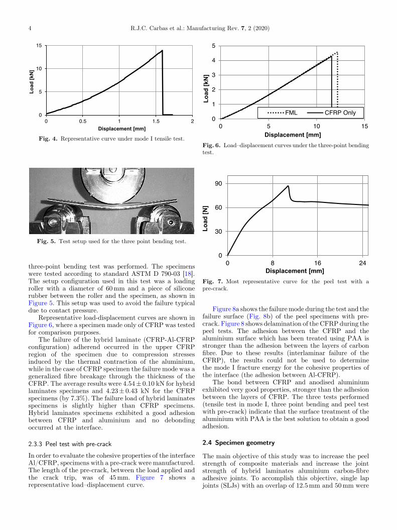
Fig. 4. Representative curve under mode I tensile test.
Fig. 5. Test setup used for the three point bending test.
Fig. 6. Load–displacement curves under the three-point bendingtest.
Fig. 7. Most representative curve for the peel test with apre-crack.
4 R.J.C. Carbas et al.: Manufacturing Rev. 7, 2 (2020)
three-point bending test was performed. The specimenswere tested according to standard ASTM D 790-03 [18].The setup configuration used in this test was a loadingroller with a diameter of 60mm and a piece of siliconerubber between the roller and the specimen, as shown inFigure 5. This setup was used to avoid the failure typicaldue to contact pressure.
Representative load-displacement curves are shown inFigure 6, where a specimen made only of CFRP was testedfor comparison purposes.
The failure of the hybrid laminate (CFRP-Al-CFRPconfiguration) adherend occurred in the upper CFRPregion of the specimen due to compression stressesinduced by the thermal contraction of the aluminium,while in the case of CFRP specimen the failure mode was ageneralized fibre breakage through the thickness of theCFRP. The average results were 4.54± 0.10 kN for hybridlaminates specimens and 4.23± 0.43 kN for the CFRPspecimens (by 7.3%). The failure load of hybrid laminatesspecimens is slightly higher than CFRP specimens.Hybrid laminates specimens exhibited a good adhesionbetween CFRP and aluminium and no debondingoccurred at the interface.
2.3.3 Peel test with pre-crack
In order to evaluate the cohesive properties of the interfaceAl/CFRP, specimens with a pre-crack were manufactured.The length of the pre-crack, between the load applied andthe crack trip, was of 45mm. Figure 7 shows arepresentative load–displacement curve.
Figure 8a shows the failuremode during the test and thefailure surface (Fig. 8b) of the peel specimens with pre-crack. Figure 8 shows delamination of the CFRP during thepeel tests. The adhesion between the CFRP and thealuminium surface which has been treated using PAA isstronger than the adhesion between the layers of carbonfibre. Due to these results (interlaminar failure of theCFRP), the results could not be used to determinethe mode I fracture energy for the cohesive properties ofthe interface (the adhesion between Al-CFRP).
The bond between CFRP and anodised aluminiumexhibited very good properties, stronger than the adhesionbetween the layers of CFRP. The three tests performed(tensile test in mode I, three point bending and peel testwith pre-crack) indicate that the surface treatment of thealuminium with PAA is the best solution to obtain a goodadhesion.
2.4 Specimen geometry
The main objective of this study was to increase the peelstrength of composite materials and increase the jointstrength of hybrid laminates aluminium carbon-fibreadhesive joints. To accomplish this objective, single lapjoints (SLJs) with an overlap of 12.5mm and 50mm were

Fig. 8. Failure mode (a) and failure surface (b) of the peel specimen with pre-crack.
Fig. 9. Geometry of the single lap joints (all dimensions are in mm).
Fig. 11. Failure surface of the CFRP joints with an overlap of12.5mm (a) and overlap of 50mm (b).
Fig. 10. Load–displacement curves obtained for CFRP joints.
R.J.C. Carbas et al.: Manufacturing Rev. 7, 2 (2020) 5
manufactured. The width and adhesive thickness of thejoints were the same for all hybrid laminates jointsconfiguration (25mm and 0.2mm, respectively). Theconfigurations of the joints are detailed in Figure 9.
3 Experimental results of hybrid joints
The tensile tests of the SLJ’s were performed in aservohydraulic model, MTS
®
model 810, with a load cellof 100 kN, with a displacement rate of 1mm/min. Fivespecimens were tested to failure in laboratory ambientconditions (room temperature of 23 °C, relative humidity of55%).
3.1 CFRP joint
The purpose of this study was to assess the improvementsof using different hybrid laminates aluminium carbon-fibreadhesive joints configurations. In order to have abenchmark to evaluate the differences between thedifferent configurations, CFRP-only adherends wereproduced to serve as a reference for the other joints.Load–displacement curves for both 12.5mm and 50mmoverlaps are presented in Figure 10.
Typical failure surface for both overlaps can beobserved in Figure 11. The average failure load forCFRP-only joints was 12.5± 0.4 kN for the 12.5mmoverlap and 31.3±1.9 kN for the 50mm overlap. For the12.5mm overlap the failure was cohesive in the adhesive,whereas for the 50mm overlap there was clear delamina-tion of the adherends. The standard deviation for theexperimental results with 50mm overlap may be alsoaffected by the unpredictability of the delamination failure.
3.2 Hybrid laminated joint � CFRP-Al-CFRP
The first configuration of aluminium-carbon fibre lami-nates consisted of CFRP reinforced with a 0.8mm thickaluminium sheet in the middle of the adherend. Theresultant load-displacement curves can be seen inFigure 12.
The failure mode of this type of joint with 12.5mm ofoverlap length was cohesive (Fig. 13a) and with 50mm ofoverlap length delamination occurred in the CFRP(Fig. 13b).
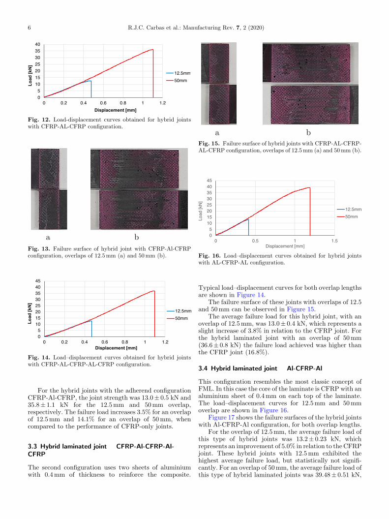
Fig. 12. Load-displacement curves obtained for hybrid jointswith CFRP-AL-CFRP configuration.
Fig. 13. Failure surface of hybrid joint with CFRP-Al-CFRPconfiguration, overlaps of 12.5mm (a) and 50mm (b).
Fig. 14. Load–displacement curves obtained for hybrid jointswith CFRP-AL-CFRP-AL-CFRP configuration.
Fig. 15. Failure surface of hybrid joints with CFRP-AL-CFRP-AL-CFRP configuration, overlaps of 12.5mm (a) and 50mm (b).
Fig. 16. Load–displacement curves obtained for hybrid jointswith AL-CFRP-AL configuration.
6 R.J.C. Carbas et al.: Manufacturing Rev. 7, 2 (2020)
For the hybrid joints with the adherend configurationCFRP-Al-CFRP, the joint strength was 13.0± 0.5 kN and35.8±1.1 kN for the 12.5mm and 50mm overlap,respectively. The failure load increases 3.5% for an overlapof 12.5mm and 14.1% for an overlap of 50mm, whencompared to the performance of CFRP-only joints.
3.3 Hybrid laminated joint � CFRP-Al-CFRP-Al-CFRP
The second configuration uses two sheets of aluminiumwith 0.4mm of thickness to reinforce the composite.
Typical load–displacement curves for both overlap lengthsare shown in Figure 14.
The failure surface of these joints with overlaps of 12.5and 50mm can be observed in Figure 15.
The average failure load for this hybrid joint, with anoverlap of 12.5mm, was 13.0± 0.4 kN, which represents aslight increase of 3.8% in relation to the CFRP joint. Forthe hybrid laminated joint with an overlap of 50mm(36.6±0.8 kN) the failure load achieved was higher thanthe CFRP joint (16.8%).
3.4 Hybrid laminated joint � Al-CFRP-Al
This configuration resembles the most classic concept ofFML. In this case the core of the laminate is CFRP with analuminium sheet of 0.4mm on each top of the laminate.The load–displacement curves for 12.5mm and 50mmoverlap are shown in Figure 16.
Figure 17 shows the failure surfaces of the hybrid jointswith Al-CFRP-Al configuration, for both overlap lengths.
For the overlap of 12.5mm, the average failure load ofthis type of hybrid joints was 13.2± 0.23 kN, whichrepresents an improvement of 5.0% in relation to the CFRPjoint. These hybrid joints with 12.5mm exhibited thehighest average failure load, but statistically not signifi-cantly. For an overlap of 50mm, the average failure load ofthis type of hybrid laminated joints was 39.48±0.51 kN,

Fig. 17. Failure surface of hybrid joint with AL-CFRP-ALconfiguration, overlaps of 12.5mm (a) and 50mm (b).
Table 3. Failure load and strength values for the CFRP and hybrid joints.
Fig. 18. Comparison of the failure surfaces of hybrid jointswith an overlap of 50mm: (a) CFRP-only; (b) CFRP-Al-CFRP;(c) CFRP-Al-CFRP-Al-CFRP; (d) Al-CFRP-Al.
R.J.C. Carbas et al.: Manufacturing Rev. 7, 2 (2020) 7
which represents an improvement of 26.0% in relation tothe CFRP joint.
3.5 Comparison of SLJ’s results
Table 3 summarizes the experimental results of theCFRP and hybrid joints for two overlap lengths (12.5and 50mm).
A slight increase of the joint strength was observed inhybrid joints with an overlap of 12.5mm, but the loadincrease was smaller than the standard deviation obtainedexperimentally in the CFRP joints. The failure wascohesive in all specimens, and since the joint strength ismore dependent on the adhesive rather than the adherends,
this justifies the residual variation of joint strength as afunction of hybrid joint configuration. For the 50mmoverlap, the CFRP joint suffered delamination. With theconfigurations CFRP-Al-CFRP and CFRP-Al-CFRP-Al-CFRP, the failure mechanism was also delamination, butless severe when in comparison with the reference joint (seeFig. 18). This suggests an increase in the peel strength ofthe adherends, since the peel stresses are the major causefor the occurrence of delamination [19]. Regarding joint

Fig. 19. Traction-separation law with linear softening lawavailable in ABAQUS
®
.
8 R.J.C. Carbas et al.: Manufacturing Rev. 7, 2 (2020)
strength, an increase in the failure load was also verified,more significant than the increases for the 12.5mm overlap.The failure mechanism was different for the Al-CFRP-Alconfiguration. It was cohesive in the adhesive, indicating afurther improvement in the through-thickness propertiesrelative to the other configurations. The fact that theCFRP layer is located further away than the adhesive layerreduces the effect of the peel stresses at the edges of theoverlap in the CFRP. Since the failure was cohesive, anddespite of the presence of an adhesive failure in some points,a more significant increase in the lap shear strength wasexpected, corresponding to the shear strength value for theadhesive.
4 Numerical analysis of hybrid joints
Cohesive zone model (CZM) can predict the formationand propagation of cracks [20,21]. The triangular CZM,due to its simplicity, is widely used and provides goodresults for most of the real situations [22]. This cohesivelaw is based on a relation between stresses and relativedisplacements (in tension or shear) connecting pairednodes of the cohesive elements (Fig. 19), to simulate aninitial elastic behaviour up to tn
0 (tension) or ts0 (shear).
After the maximum stress is achieved, linear softeninginitiates. When the stress reaches the value of zero, noload can be transmitted, which is the same as saying thata crack has been created. dn and ds represent thenormal and the shear maximum relative displacements,respectively.
FEAwas performed using ABAQUS program (DassaultSystèmes Simulia Corp. Providence, RI, USA) using CZMby developing a 2D model to predict the failure loads andfailure type for each hybrid metal laminates configuration.The adherends were modelled using a 4 node bilinear planestrain quadrilateral element (CPE4R), while the adhesivelayer was modelled using a 4 node cohesive elements(COH2D4).
4.1 Thermal stress evaluation
CFRP have a very low coefficient of thermal expansion inthe direction of the fibres, close to 0mmm�1 K�1, while2024-T3 aluminium alloy has a linear thermal coefficient of22.8mmm�1 K�1. To better understand the thermalstresses of hybrid laminates plates during the cure, anasymmetric lay-up (CFRP-Al) with a thickness of 3.2mmand length of 300mm (similar to the dimensions usedexperimentally) was numerically analysed. The CFRPused in this study cures at 130 °C for 1 h and then cools toroom temperature. Therefore, in order to simulate theexperimentally used cure process, in the numerical analysisa temperature gradient of 130 °C for the initial step and20 °C (room temperature) for the final step was applied.The equivalent von Mises stress (Fig. 20) has a maximumvalue of 209MPa for the aluminium alloy and 163MPa forthe CFRP in contact with the aluminium.
This analysis shows that the residual thermal stressescannot be ignored when a material with different thermalexpansion coefficients and asymmetric configurations (e.g.CFRP-Al) is used. The stress values due to thermalexpansion are very high, considering the fact that the yieldstrength of this alloy is 289MPa, and due to this fact thishybrid laminate configuration (CFRP-Al) was not used.This behaviour is in accordance with the study performedby Fu et al. [23], which showed that the thermalpostbuckling deflection of hybrid laminates plates becomessignificant with the increase of thermal loads. The otherlay-up configurations are symmetric (e.g. CFRP-Al-CFRPor Al-CFRP-Al) and the thermal stresses present in theAl-CFRP interface are also symmetric and so the plateremains flat. After cooling, the residual thermal stresses ofone Al-CFRP interface are alleviated by the symmetricconfiguration. The same behaviour is not observed for theplates that show asymmetric layup configurations, as inthis case the residual thermal stresses can promote thebuckling deflection of hybrid laminates plates after cooling.
4.2 Hybrid joint model
An FEM analysis was performed including geometricalnon-linear effects and CZM was used to model the materialbehaviour. Triangular traction-separation laws were usedto simulate the damage evolution. The composite adher-ends used are unidirectional, in order to properly simulatethe experimental behaviour. The placement and orienta-tion of the cohesive elements used in the models wereselected in order to enable the reproduction of theexperimentally identified failure. The mechanical proper-ties of the material used are shown in Tables 1 and 2.The models were locally refined in order to better simulatethe experimental behaviour in locations where largestress concentration arise, such as at the ends of overlaplength.
The boundary conditions were consistent in all thesimulations and they are shown in Figure 21. The left end ofthe joint was fixed while in the right end a displacementwas applied to replicate the loading. The joint wasrestrained transversely on the free ends of each adherends.
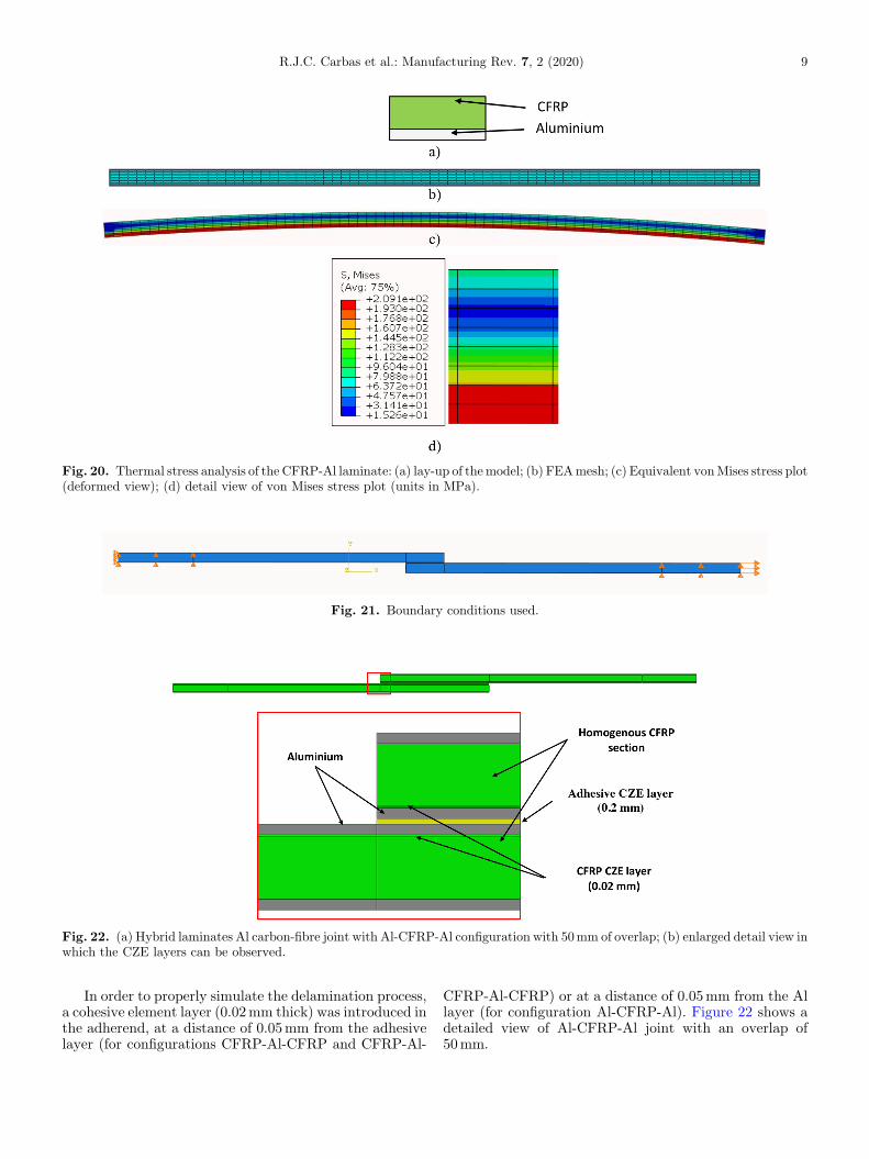
Fig. 20. Thermal stress analysis of the CFRP-Al laminate: (a) lay-up of themodel; (b) FEAmesh; (c) Equivalent vonMises stress plot(deformed view); (d) detail view of von Mises stress plot (units in MPa).
Fig. 21. Boundary conditions used.
Fig. 22. (a) Hybrid laminates Al carbon-fibre joint with Al-CFRP-Al configuration with 50mm of overlap; (b) enlarged detail view inwhich the CZE layers can be observed.
R.J.C. Carbas et al.: Manufacturing Rev. 7, 2 (2020) 9
In order to properly simulate the delamination process,a cohesive element layer (0.02mm thick) was introduced inthe adherend, at a distance of 0.05mm from the adhesivelayer (for configurations CFRP-Al-CFRP and CFRP-Al-
CFRP-Al-CFRP) or at a distance of 0.05mm from the Allayer (for configuration Al-CFRP-Al). Figure 22 shows adetailed view of Al-CFRP-Al joint with an overlap of50mm.

Fig. 23. Comparison between the experimental and the FEAload vs displacement curves for CFRP joints.
Table 4. Comparison between the damage obtained by FEA (damage variable SDEG) and experimentally for theCFRP joint.
10 R.J.C. Carbas et al.: Manufacturing Rev. 7, 2 (2020)
The thermal residual stresses due to the difference inthe thermal expansion coefficient between CFRP andaluminium are a major concern for this type of material. Inorder to take into account the physical behaviour thatoccur during the cure process of the joints, an intermediatestep before applying the displacement is created, with thecure temperature of the adhesive. In the following step,room temperature was imposed. This difference intemperature will simulate the effect of the cure of theadhesive in the hybrid adherends, and consider the thermalresidual stresses existent in the adherends. The CTE forCFRP was considered 0mm/mK�1.
4.3 Strength prediction
The load displacement curves obtained from the FEA forboth 12.5 and 50mm are compared with experimentalcurves in Figure 23.
Despite the fact that the predictions are slightly higher,the model can be considered accurate and is able to give agood prediction for the failure load. The damage obtainedby FEA occurs when the scalar stiffness degradationvariable (SDEG) reaches 1. For values of SDEG higherthan zero signifies that the damage starts. In Table 4 it ispossible to compare the type of failure predicted by theFEA analysis and the failure surfaces for both overlaps.
In the numerical models, for an overlap of 12.5mm, thedamage occurs first in the adhesive, with the CZE in thecarbon fibre already damaged. For the 50mm overlap, it isclear that the damage in the CZE of the carbon fibrereaches its peak first, while there is already some damage inthe adhesive at the edges of the overlap. These results arecoherent with the experimental data, where the delamina-tion of the adherends was evident, with the adhesive at thisedges showing a slightly different colour than the rest of thebonded length, indicating some plastic deformation. This isexplained by the stress concentration on the edges of thebonded area, where the peel stresses are maximum.
Regarding the numerical results for the hybrid joints,both CFRP-Al-CFRP and CFRP-Al-CFRP-Al-CFRPconfigurations showed the same behaviour as the CFRP

Table 5. Comparison between the damage obtained by FEA (damage variable SDEG) and experimentally for thehybrid joints with Al-CFRP-Al configuration.
Fig. 25. Comparison between FEA predictions and experimen-tal results for the failure load of specimens with a 50mm overlap.
Fig. 24. Comparison between FEA predictions and experimen-tal results for the failure load of specimens with a 12.5mmoverlap.
R.J.C. Carbas et al.: Manufacturing Rev. 7, 2 (2020) 11
joints. The failure was cohesive in the adhesive for the12.5mm overlap and delamination in the hybridadherends occurred for the 50mm overlap. For thehybrid joints with Al-CFRP-Al configuration, thedamage predicted by the FEA and the fracture surfaceobtained experimentally for this lay-up are shown inTable 5.
As obtained experimentally, the FEA analysis for theAl-CFRP-Al configuration resulted in a cohesive failure forboth overlaps. In both cases there is some damage in the
CFRP cohesive layer, but it is clear that the failure occursin the adhesive. It is possible to conclude that all themodelspredicted correctly the failure mode for all the lay-upconfigurations and overlaps.
5 Discussion of hybrid joints performance
Figures 24 and 25 compare the experimental and predictionresults of the joints.
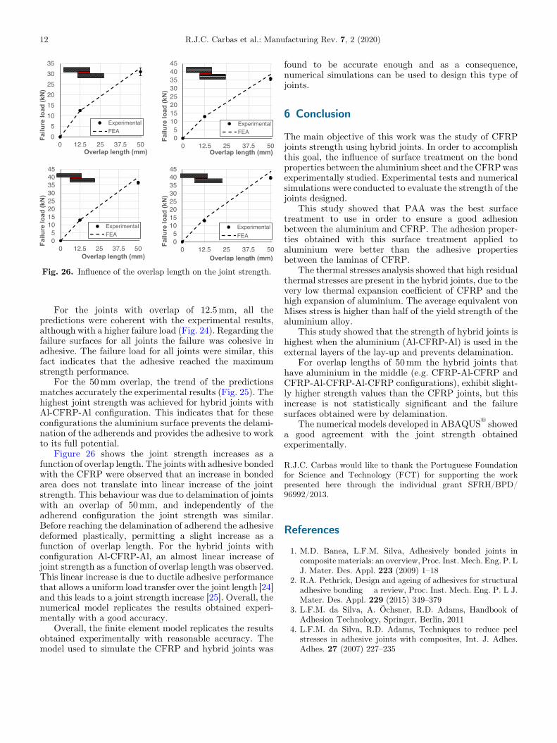
Fig. 26. Influence of the overlap length on the joint strength.
12 R.J.C. Carbas et al.: Manufacturing Rev. 7, 2 (2020)
For the joints with overlap of 12.5mm, all thepredictions were coherent with the experimental results,although with a higher failure load (Fig. 24). Regarding thefailure surfaces for all joints the failure was cohesive inadhesive. The failure load for all joints were similar, thisfact indicates that the adhesive reached the maximumstrength performance.
For the 50mm overlap, the trend of the predictionsmatches accurately the experimental results (Fig. 25). Thehighest joint strength was achieved for hybrid joints withAl-CFRP-Al configuration. This indicates that for theseconfigurations the aluminium surface prevents the delami-nation of the adherends and provides the adhesive to workto its full potential.
Figure 26 shows the joint strength increases as afunction of overlap length. The joints with adhesive bondedwith the CFRP were observed that an increase in bondedarea does not translate into linear increase of the jointstrength. This behaviour was due to delamination of jointswith an overlap of 50mm, and independently of theadherend configuration the joint strength was similar.Before reaching the delamination of adherend the adhesivedeformed plastically, permitting a slight increase as afunction of overlap length. For the hybrid joints withconfiguration Al-CFRP-Al, an almost linear increase ofjoint strength as a function of overlap length was observed.This linear increase is due to ductile adhesive performancethat allows a uniform load transfer over the joint length [24]and this leads to a joint strength increase [25]. Overall, thenumerical model replicates the results obtained experi-mentally with a good accuracy.
Overall, the finite element model replicates the resultsobtained experimentally with reasonable accuracy. Themodel used to simulate the CFRP and hybrid joints was
found to be accurate enough and as a consequence,numerical simulations can be used to design this type ofjoints.
6 Conclusion
The main objective of this work was the study of CFRPjoints strength using hybrid joints. In order to accomplishthis goal, the influence of surface treatment on the bondproperties between the aluminium sheet and the CFRPwasexperimentally studied. Experimental tests and numericalsimulations were conducted to evaluate the strength of thejoints designed.
This study showed that PAA was the best surfacetreatment to use in order to ensure a good adhesionbetween the aluminium and CFRP. The adhesion proper-ties obtained with this surface treatment applied toaluminium were better than the adhesive propertiesbetween the laminas of CFRP.
The thermal stresses analysis showed that high residualthermal stresses are present in the hybrid joints, due to thevery low thermal expansion coefficient of CFRP and thehigh expansion of aluminium. The average equivalent vonMises stress is higher than half of the yield strength of thealuminium alloy.
This study showed that the strength of hybrid joints ishighest when the aluminium (Al-CFRP-Al) is used in theexternal layers of the lay-up and prevents delamination.
For overlap lengths of 50mm the hybrid joints thathave aluminium in the middle (e.g. CFRP-Al-CFRP andCFRP-Al-CFRP-Al-CFRP configurations), exhibit slight-ly higher strength values than the CFRP joints, but thisincrease is not statistically significant and the failuresurfaces obtained were by delamination.
The numerical models developed in ABAQUS®
showeda good agreement with the joint strength obtainedexperimentally.
R.J.C. Carbas would like to thank the Portuguese Foundationfor Science and Technology (FCT) for supporting the workpresented here through the individual grant SFRH/BPD/96992/2013.
References
1. M.D. Banea, L.F.M. Silva, Adhesively bonded joints incompositematerials: an overview, Proc. Inst.Mech. Eng. P. LJ. Mater. Des. Appl. 223 (2009) 1–18
2. R.A. Pethrick, Design and ageing of adhesives for structuraladhesive bonding � a review, Proc. Inst. Mech. Eng. P. L J.Mater. Des. Appl. 229 (2015) 349–379
3. L.F.M. da Silva, A. Öchsner, R.D. Adams, Handbook ofAdhesion Technology, Springer, Berlin, 2011
4. L.F.M. da Silva, R.D. Adams, Techniques to reduce peelstresses in adhesive joints with composites, Int. J. Adhes.Adhes. 27 (2007) 227–235

R.J.C. Carbas et al.: Manufacturing Rev. 7, 2 (2020) 13
5. T.M. Koh, S. Feih, A.P.Mouritz, Strengtheningmechanics ofthin and thick composite T-joints reinforced with z-pins,Compos. P. A Appl. Sci. Manuf. 43 (2012) 1308–1317
6. S. Ucsnik, M. Scheerer, S. Zaremba, D.H. Pahr, Experimen-tal investigation of a novel hybrid metal-composite joiningtechnology, Compos. P. A Appl. Sci. Manuf. 41 (2010)369–374
7. A. Asundi, A.Y.N. Choi, Fiber metal laminates: an advancedmaterial for future aircraft, J. Mater. Process. Technol. 63(1997) 384–394
8. R. Alderliesten, On the development of hybrid materialconcepts for aircraft structures. Recent Pat. Eng. 3 (2009)25–38
9. C.A.J.R. Vermeeren, An historic overview of the develop-ment of fibre metal laminates, Appl. Compos. Mater. 10(2003) 189–205
10. S. Hinz, T. Omoori, M. Hojo, K. Schulte, Damagecharacterisation of fibre metal laminates under interlaminarshear load, Compos. Part A 40 (2009) 925–931
11. H. Nakatani, T. Kosaka, K. Osaka, Y. Sawada, Damagecharacterization of titanium/GFRP hybrid laminates sub-jected to low-velocity impact, Compos. Part A 42 (2011)772–781
12. P. Cortés, W.J. Cantwell, The fracture properties of a fibre–metal laminate based on magnesium alloy, Compos. Part B37 (2006) 163–170
13. D.G.D. Santos, R.J.C. Carbas, E.A.S. Marques, L.F.M. daSilva, Reinforcement of CFRP joints with fibre metallaminates and additional adhesive layers, Compos. Part BEng 165 (2019) 386–396
14. X. Shang, E.A.S. Marques, J.J.M. Machado, R.J.C. Carbas,D. Jiang, L.F.M. da Silva, A strategy to reduce delaminationof adhesive joints with composite substrates, Proc. Inst.
Mech. Eng. P. L J. Mater. Des. Appl. 233 (2019),521–530
15. T. Sinmazçelik, E. Avcu, M.Ö. Bora, O. Çoban, A review:fibre metal laminates, background, bonding types andapplied test methods, Mater. Des. 32 (2011) 3671–3685
16. W.X. Wang, Y. Takao, T. Matsubara, Galvanic corrosion-resistant carbon fiber metal laminates, in Procedings ofICCM-16 Conference, Kyoto, July, 2007
17. ASTM D 3933-98. Standard Guide for Preparation ofAluminium Surfaces for Structural Adhesives Bonding(Phosphoric Acid Anodizing), 1998
18. ASTM D 790-03. Standard test methods for flexuralproperties of unreinforced and reinforced plastics andelectrical insulating materials, 2003
19. L.J. Hart-Smith, Adhesive-bonded single-lap joints, NASALangley contract report NASA CR-112236, 1973
20. L.F.M. da Silva, R.D.S.G. Campilho, Advances in numericalmodelling of adhesive joints, Springer Briefs in Computa-tional Mechanics, 2012
21. R.A. Sauer, A survey of computational models for adhesion,J. Adh. 92 (2016) 81–120
22. C.D.M. Liljedahl, A.D. Crocombe, M.A. Wahab, I.A.Ashcroft, Damage modelling of adhesively bonded joints,Int. J. Fract. 141 (2006) 147–161
23. Y. Fu, J. Zhong, Y. Chen, Thermal postbuckling analysis offiber–metal laminated plates including interfacial damage,Compos. Par B 56 (2014) 358–364
24. D.F.S. Saldanha, C. Canto, L.F.M. da Silva, R.J.C. Carbas,F.J.P. Chaves, K. Nomura, T. Ueda, Mechanical characteri-zation of a high elongation and high toughness epoxyadhesive, Int. J. Adhes. Adhes. 47 (2013) 91–98
25. M. Goland, E. Reissner, The stresses in cemented joints, J.Appl. Mech. 11 (1944) A17–A27
Cite this article as: Ricardo J.C. Carbas, Miguel P. Palmares, Lucas F.M. da Silva, Experimental and FE study of hybridlaminates aluminium carbon-fibre joints with different lay-up configurations, Manufacturing Rev. 7, 2 (2020)