experimental analysis of radio communication capabilities
TRANSCRIPT
Experimental Analysis of Radio Communication Capabilities ofMultiple Autonomous Surface Vehicles
Sharaf Malebary1, Jason Moulton2, Alberto Quattrini Li3, and Ioannis Rekleitis21Information Technology Department, King Abdulaziz University
Email: [email protected] Science and Engineering Department, University of South Carolina
Email: [email protected] and [email protected] Science Department, Dartmouth College
Email: [email protected]
Abstract—Autonomous exploration and rescue vehicles havebeen gaining wide interest over the past few years. Nowadays,demonstrations showed that those vehicles can fly, dive, surf, ordrive while carrying out missions autonomously in some specificscenarios. Monitoring vehicles during missions is a crucial andchallenging task to avoid the unnecessary cost of losing vehicles orpotential accidents. In this paper, we present a cheap yet effec-tive way for monitoring and communicating with autonomousvehicles over long distances by using off-the-shelf 900 MHzmodems namely RFD900+ and high gain antennas. Althoughthe 900 MHz band has been around for over two decades,no complete analysis exists providing guidelines to use off theshelf modems for point-to-point and multi-point communications.Our main contribution is to provide experimental analysis ofthe communication capabilities in point-to-point and multi-pointscenarios in both line of sight (LOS) and non line of sight (N-LOS) using an affordable setup ($70 per modem). Experimentswere carried out using autonomous surface vehicles (ASVs) asremote nodes and computers as Ground Control Stations (GCSs).
I. INTRODUCTION
The rapid advancement in sensor modalities enables fleets ofrobots to carryout their missions autonomously and efficientlyby maintaining reliable communication links between themand base-stations [1]. Robots nowadays are more sophisti-cated in terms of exploration capability (drive, fly, and diveautonomously) based on sensory data. However, monitoringexploring robots during a mission is still crucial to minimizepotential loss (financially or injury in case of accidents).Hence, it is essential to provide low latency, reliable, androbust communication channels to ensure continuous andeffective monitoring of autonomous robots during missions.The desirable range along with the number of nodes are thekey factors that define the frequency band (VHF, UHF, SHF,etc.) to be used in the radio spectrum for communications.Several other factors contribute to degrading the quality ofcommunications, such as, but not limited to, environmentalnoise and weather outdoors, and walls, obstacles, and spectrumoverlap indoors.
Various technologies are widely used nowadays and haveproven their effectiveness in communications. Some examplesof these types of communications that can be seen in our dailylives are, Wi-Fi, Wimax, Zigbee, Bluetooth, etc. Although
Fig. 1. Jetyaks equipped with RFD900+ modems.
most of these wireless technologies allow bi-directional com-munications, they differ in several technical aspects such ascommunication range, bandwidth, data rate, latency, and areprone to noise. Additionally, an important aspect to consideris the cost factor. Therefore, driven by these observations,our work was done in an effort to use cheap off-the-shelf900MHz modems to test their capabilities for long rangecommunications among a fleet of autonomous vehicles. It isworth mentioning that there exists 900 MHz industrial solutionfor long distance communication, e.g., AWK-3191 Series1.The aforementioned series can cover up to 30 km in line ofsight (LOS) at 6Mbps for point-to-point connection and 5 kmin LOS for point-to-multi-point at the same rate. The cost forsuch a device ranges between $1999 - $2199.
This paper presents a performance evaluation that can beused as a guide to understand the capability and reliabilityof long range communications. Such a study can then beused to establish a better network for a team consistingof multiple robots in marine environments, where networkinfrastructure might not be available and long range distancecommunication is necessary. We focus on communicating inthe ISM Band (900MHz) when experimenting indoors andoutdoors, because of the low-cost/weight of the hardware, andthe potential to cover longer ranges with better penetrationthrough obstacles than higher frequencies. In particular, we usecheap, off-the-shelf Radio Frequency (RF) modems – OpenSource RFD900+2 (widely used for peer-to-peer telemetrycommunications). Several indoor and outdoor experiments
1https://www.moxa.com/doc/brochures/Brochure-AWK-3191.pdf/2http://store.rfdesign.com.au/rfd-900p-modem/
978-1-5386-4814-8/18/$31.00 ©2018 IEEE

show how different network configurations affect the quality ofcommunication in terms of latency, range, data rate and RSSI(Received Signal Strength Indicator) value. Specifically, in in-door environments we assume stationary robots due to limitedspace. In outdoor environments, experiments were conductedby mounting RFD900+ hardware on a fleet of AutonomousSurface Vehicles (ASV) masts (expanding on the WHOI Jetyak[2]); see Fig. 1. Different experimental dimensions, includingthe number of robots and the network topology with a basestation, have been evaluated. The main contribution of thispaper is to give an insight of the different setups that can beeasily adopted when monitoring autonomous vehicles usingbasic hardware and how to optimize and tune parameters toachieve higher throughput and range. We also provide a fruitfulcomparison between the quality of communications in LOS vs.N-LOS in point-to-point and multi-points connections.
The rest of this paper is organized as follows. Related workis provided in Section II. Section III details the experimentalsetup including the platforms, dimensions, and metrics used.Results are given and discussed in Section IV. The paperconcludes in Section V with discussion regarding future work.
II. RELATED WORK
Several works exist that utilize wireless communicationsamong a fleet of autonomous vehicles. These works providesystems for communicating with robots and base stationover different bands of the RF spectrum. Hayat et al. [3]demonstrated in their work the feasibility of maintaining linksbetween multiple drones and base stations in single and multi-hop manner. Their work showed promising results by adoptingthe Wi-Fi band (802.11n, ac) for communications, althoughcommunicating in Wi-Fi band is limited in range up to acouple of hundred meters. Asadpour et al. [4] provided athorough analysis of micro unmanned aerial vehicle networksin the physical and media access control (MAC) layers. Intheir testbed, the authors employed ad-hoc Wi-Fi 802.11nfor high-speed traffic and long-range XBeePro over 2.4GHzas the control channel. Morgenthaler et al. developed theUAVNet prototype that forms a flying wireless mesh network[5]. Results showed 6.3 times higher throughput in flyingwireless mesh nodes than a ground-based network approach.In [6], Kimball et al. have successfully built an AutonomousSurface Vehicle (ASV) that can acquire oceanographic datain shallow or dangerous water. The authors used 3D Robotics900MHz radios for communications with a computer operatedby a human and were able to achieve up to 1 km range tocommunicate with a single ASV. Additionally, Beard et al.[7] used the 900MHz bidirectional link between a singleUnmanned Aerial Vehicle (UAV) and a laptop (Ground station)where the laptop up-links trajectory commands to the UAVwhich, in turn, down-links positioning and status data at 20Hzto the laptop.
A complete analysis in point-to-point and multi-points com-munications among autonomous vehicles using 900MHz bandfor long range communications is still missing, gap that thiswork addresses.
Fig. 2. RFD900+ modem installed in a waterproof box, connected by FTDIcable.
Fig. 3. Live monitoring of 2 ASVs communicating with 1 GCS at theCongaree river in South Carolina using Mission Planner (Ground ControlSoftware).
Fig. 4. Live monitoring of 3 ASVs deployed at Lake Murray. Data wascollected from various experiments where each ASV was connected to aseparate GCS operating on different Net IDs, and this illustration where allwere monitored by a single GCS. All BSs were connected to laptops stationedat shore running Mission Planner software for monitoring and data collection.

III. EXPERIMENTAL SETUP
To evaluate the capabilities of long range communicationsusing 900MHz band in both point-to-point and multi-pointscenarios, we first need to take a look at the various parametersthat can be adjusted by the user. These parameters are closelyrelated and can greatly affect the performance of the commu-nication. Table I lists the available and configurable parametersin the RFD900+ modems as well as the default (out of box),minimum, and maximum value for each parameter.
TABLE IRFD900+ CONFIGURABLE PARAMETERS WITH THEIR MINIMUM,
MAXIMUM AND DEFAULT (OUT OF BOX) VALUES
Parameter Description Default Max Min
Format EEPROM Version — — —Serial Speed Serial data rate (unit: kB) 57 115 2Air Speed Data rate (unit: kB) 64 250 2Net ID Network ID 25 499 0Tx Power unit: dBm 20 30 0ECC Error correction code 0 1 0Mavlink Mavlink frame & report 0 1 0Op Resend Opportunistic resend 0 1 0Min Freq In kHz 915 927 902Max Freq In kHz 928 928 903Num Channel Frequency hopping channels 20 50 5Duty Cycle Percentage of transmission 100 100 10LBT RSSI Listen before talk 0 1 0Manchester Manchester encoding 0 1 0RTS/CTS Request/Clear to send 0 1 0Node ID Unique ID for each node 2 29 0Node Dest Remote ID 65535 29 0Sync Any Broadcast feature 0 1 0Node Count Total number of nodes 2 30 2
A. Platforms
We adopt an ASV from the WHOI project [2] custom-modified in our lab to serve as remote autonomous nodes.The RFD900+ modems were mounted on the mast (Fig. 1) ofeach ASV to minimize any interference that may be causedby other on-board electrical and electronic components, e.g.,GPS module, Gyroscope, Compass, Accelerometer Sensors.
B. Dimensions
Many factors are crucial to take into consideration whenevaluating wireless communications. The desired range, num-ber of nodes, surrounding noise, and obstacles between trans-mitters and receivers are the most common and widely usedto analyze communication quality. The aforementioned factorscan be considered environmental. In the following, we detailour experimental setup and the consideration we took forrunning our tests.
1) Hardware: We employ half wave dipole antennas ap-proximately 3 dBi gain with omni directional radiation pattern.It is reported on the RFD900p manufacturer data-sheet thatdepending on the antennas installed, communications can becarried for up to 40km in case of LOS3. Hence, we adopt suchhigh gain antenna to be used in BSs and ASVs to validate thisclaim.
3http://files.rfdesign.com.au/Files/documents/RFD900/20DataSheet.pdf/
Fig. 5. Electronics box of the ASV, which contains controllers and sensors,including GPS and Arduino. Each of the components can be a source of noise.
Fig. 6. GPS traces of the four ASVs during a deployment at the Congareeriver in N-LOS.
2) Number of nodes: We can summarize our experimentsinto two main categories: A point-to-point and multi-pointscenarios. The first scenario consists of one ASV and oneBase Station (BS), equipped with the same RFD900+ modem,connected to a laptop through a serial to USB cable (see Fig.2). In the multi-point scenario, several setups are tested, whereone ASV broadcasts to two separate BSs to emulate multipleGCSs monitoring the same vehicle (Fig. 3). Another setupconsists of multiple ASVs monitored by a single BS at thesame time (Fig. 4).
3) LOS vs. Non-line of sight (N-LOS): We explicitly con-sider scenarios under LOS and N-LOS as experimental dimen-sion, to see how robust the quality of communication is.

Fig. 7. GPS trace-path of deployed ASV on Lake Murray to evaluatecommunication between BS and ASV in LOS. Yellow traces represent lowlatency, orange represent ASV executing way-point missions, and blue tracesevaluate the quality of communication and range limitation.
C. Metrics
We collect two sets of data, telemetry logs (T-logs) andbinary (Bin) logs. Both of these types of logs contain mostlythe same data from the ASV sensors and modules. HoweverT-logs gets streamed live to the GCS/BS using the RFD900+modems and the Bin logs get stored locally for collection later.Therefore, different information can be extracted from theselogs depending on the type of evaluations. For instance, T-logsprovide channel metrics such as RSSI, Noise, and receivingerror for Local and Remote nodes Figures 3 and 4, whichdefine the Link quality between transmitters and receivers,while Bin logs are more reliable for obtaining sensitive data(i.e., GPS traces) due to local logging in the ASVs on-boardstorage Figures 6 and 7.
1) Noise: Several types of noise are well known to have adetrimental impact on the quality of the wireless communica-tions, degrading the quality of the communication link: datatransfer rate as well as communication range can dramaticallydrop, especially when operating outdoors. Examples of com-mon types of noise are environmental noise – e.g., weather– and hardware – e.g., thermal, noise from the ASV’s enginemagneto. Also, in case of multiple nodes communicating atclose distance, each node can be considered a noise source toits neighbor. For simplicity, we categorize the noise measuredat GCS and ASV into local noise and remote noise.
2) RSSI: A positive value that represents the strengthof the signal. It is different than Received Signal Strength(RSS) which defines the actual strength value of the signalrepresented by a negative value.
3) Rx error: Represents the error rate in receiving data overair, i.e., packets that didn’t pass CRC check.
4) Distance: The distance between transmitter and receiverwhich can be ASV or BS.
D. Scenarios
In this section, we describe the scenarios to collect data,according to the dimensions just mentioned. All scenarios can
be categorized based on the location where the experimentswere conducted. As said, a key factor when dealing withwireless communication that have a great impact on the link-quality is the presence of LOS between communicating nodes.Therefore, we pick two locations namely Lake Murray andCongaree River, to represent communicating in LOS and inN-LOS respectively as follows:
1) Lake Murray (LOS): Lake Murray is about 50,000 acresof open space with minimal obstacles. Therefore, we choose toconduct experiments at this location due to convenience (closeto our lab) and optimal conditions (minimal obstacles). Herewe setup our scenarios to evaluate the maximum range thatcan be covered when deploying ASVs in LOS environment,while maintaining reliable monitoring. In particular, we runthe following experiments:
i) A pair of one ASV and one BS.ii) Two pairs of one ASV and one BS.
iii) Three pairs of one ASV and one BS.iv) Two ASVs connected to one BS, and one ASV con-
nected to a separate BS with different Network-ID.
2) Congaree River (N-LOS): We nominate the CongareeRiver to run and collect data in a N-LOS scenarios. Thewinding path of the river and bushy surroundings make thisan optimal location for testing and evaluating the quality ofcommunication when there is no visible path between the BSand ASVs (Fig. 6). We conduct several experiments that aredifferent than the ones at the lake. More complicated scenarioswere run at the river to verify the accuracy of the results.Intuitively one can expect to run smoother experiments at thelake than at the river due to space limitation and surroundingobstacles. Hence, we start with one pair of BS and ASV asa point-to-point scenario. Then, we introduce several (up tothree) ASVs to the network totaling four ASVs and three BSconnected to two laptops as follows:
i) One ASV and One BS forming a point-to-point scenario.ii) One ASV broadcasting to two BSs at the same time,
where each BS is connected to separate GCS represent-ing an ASV being monitored by multiple GCSs.
iii) Two ASVs connected to one BS.iv) Two pairs of one ASV and one BS, where each pair is
assigned with different Network-ID.v) Two ASVs connected to one BS, and one ASV con-
nected to a separate BS at the same time but withdifferent Network-ID.
vi) Two pairs of one ASV connected to one BS, and twoASVs connected to one BS totaling four ASVs in thewater and three BSs connected to two GCSs (laptops).
In the aforementioned experiments, T-logs were collected atthe corresponding GCS as they were live-streamed. The Binlogs were setup to be stored locally at each ASV and werecollected from a 4GB SD-card located in Pixhawk boxes (Fig.5) upon the end of all experiments. Several key observationsand notes regarding the results are discussed next.

IV. SUMMARY OF RESULTS AND DISCUSSION
In this section, we provide an inclusive summary of allresults obtained from conducting experiments on Lake Murrayand Congaree river.
It is worth mentioning that it takes a significant amount oftime to carry such field experiments due to loading and haulingASVs, setting up and configuring parameters, unexpectedtechnical issues, collecting data and perform analysis. Here, wehighlight the main observations from the analysis and providea discussion that guides future setups. Figures 8 and 9 show ananalysis of one scenario at the lake and the river respectively.
A. Impact of number of ASVs
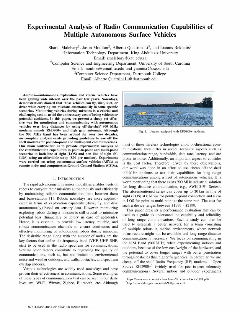
By setting up a point-to-point communication, i.e., oneASV and one BS, we observed a low latency and reliablecommunication in the lake and the river. We configured thenodes to communicate at the maximum available data rate i.e.,250 kbps. As for the duty cycle, we kept the ASV at 100%transmission cycle since we cared about monitoring the ASV.The BS was given the node ID 0, the ASV node ID 1, andthey were both configured to communicate with each other bysetting up the node destination variable Table II. When anotherASV joins the network (with the same configuration), a drasticchange to RSSI values is observed, as shown for examplein Figure 10. Nodes can no longer communicate with BS oramong themselves. We started from the maximum values thatallowed by the modems then worked our way down until wewere able to upload missions and monitor all ASVs at the BSs.For instance, we altered the data-rate to be at 128 kbps andcut down duty cycle to 40% for each ASV and 20% for theBS. Additionally, we configured all the node to communicatein a broadcasting behavior by assigning the following values:node destination = 65535, SYNC any = 1, and RTS/CTS = 1.Fig. 11 shows the RSSI and Noise values of the configurationthat gave the best results in our experiments in point-to-pointand multi-point cases.
B. Impact on range
Experiments conducted at the river, in a N-LOS environ-ment, showed a reliable monitoring of multiple ASVs (upto 3, monitored by 2 BSs) for up to 1 km range. The sameconfiguration provided a range up to 5 km at Lake Murrayin a LOS environment. Also, as expected, the range extendswith the fewer number of ASVs in the network due to theabsence of noise created by neighboring nodes. We alsonoticed decreasing data rate results in an increase of the rangebut at the cost of the amount of data to be exchanged.
C. Discussion
Although RSSI, from the physical layer perspective, is oneof the most valuable metrics that can define the quality ofcommunication, several other metrics have to be consideredwhen evaluating the quality of communications. For instance,associating more nodes to the network may increase the valueof RSS due to signals colliding. Another important metricis the distance that can be covered. From our experiments,
Fig. 8. Analysis example of local and remote RSSI (blue and orange), noise(red and green), and receiving error (yellow) values over distance of a remote(ASV) and a local node (BS) deployed at Lake Murray in LOS. Top mapshows the full path and corresponding analysis on the left side of the map.Bottom shows a zoomed in view (segment of path and plot) when accumulatedreceiving error go beyond 20%.
Fig. 9. Analysis of 3 ASVs at the Congaree river with two BSs. Map onthe right shows three paths of ASVs. Path colors correspond to quality ofcommunication: Blue-receiving error of less than 20%, yellow-up to 49%,orange- above 50% which considered unreliable for monitoring.
four remote ASVs can be monitored in an open large areamore reliably than in a smaller area due to the noise createdfrom neighboring ASVs. Also, it is worth mentioning thattrial and error method might be the most effective way whenconfiguring modems for the following reasons. The numberof ASVs changes based on the exploring area, environmentalfactors – e.g., obstacles – other miscellaneous reasons – e.g.,antennas type, length, and placement, etc. Therefore, it is hardto find an optimal configuration that can be generalized. Onthe other hand, we observed an inverse relationship betweenthe number of ASVs vs. maximum possible data rate. Basedon the results and analysis, this relation can be defined asfollow where n is the number of remote ASVs:
Maximum possible Data rate = 250kbps/(2n − 1) (1)
V. CONCLUSIONS AND FUTURE WORK
This paper provides an insight of the different configurationsthat can be used for communicating over 900MHz band.We showed how we can utilize off the shelf models, namelyRFD900+, to provide bi-directional communications in point-to-point and multi-point setups. Based on the results, a keyobservation is that using these types of affordable modems
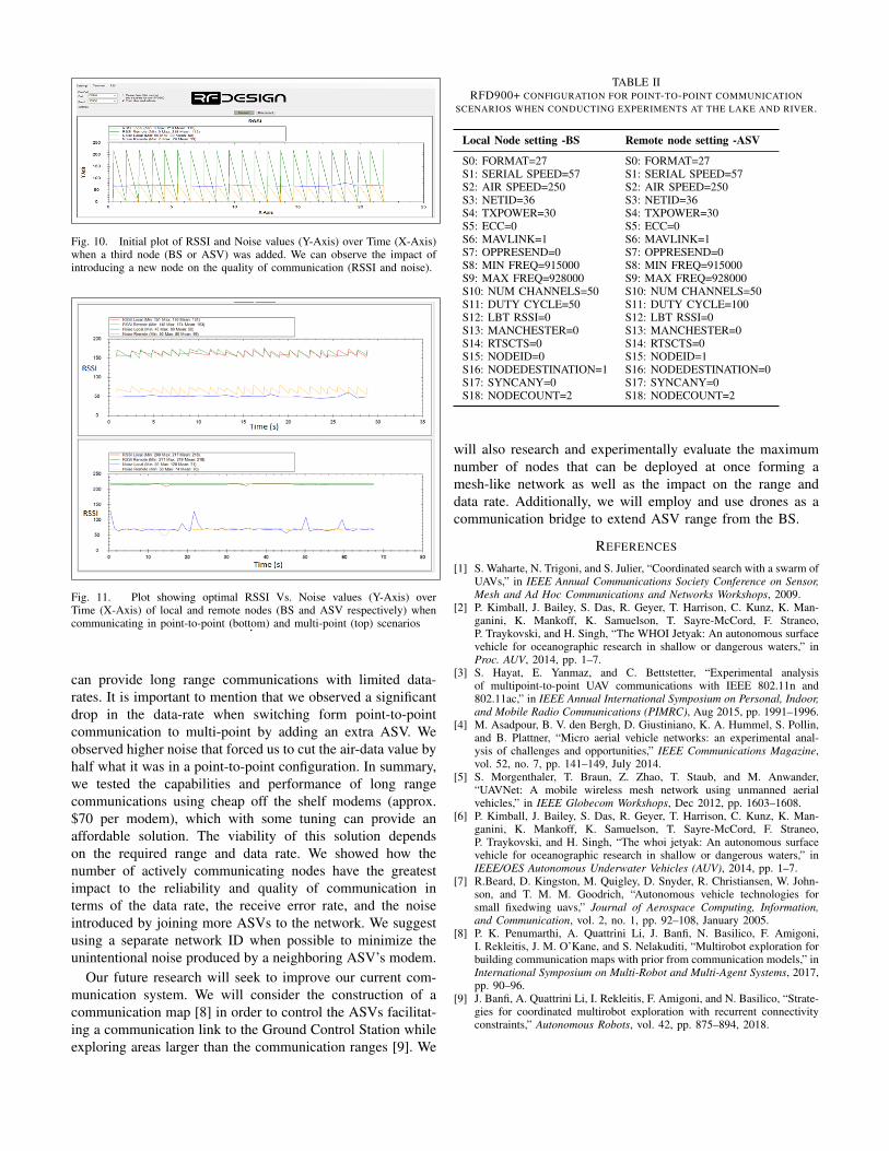
Fig. 10. Initial plot of RSSI and Noise values (Y-Axis) over Time (X-Axis)when a third node (BS or ASV) was added. We can observe the impact ofintroducing a new node on the quality of communication (RSSI and noise).
Fig. 11. Plot showing optimal RSSI Vs. Noise values (Y-Axis) overTime (X-Axis) of local and remote nodes (BS and ASV respectively) whencommunicating in point-to-point (bottom) and multi-point (top) scenarios.
can provide long range communications with limited data-rates. It is important to mention that we observed a significantdrop in the data-rate when switching form point-to-pointcommunication to multi-point by adding an extra ASV. Weobserved higher noise that forced us to cut the air-data value byhalf what it was in a point-to-point configuration. In summary,we tested the capabilities and performance of long rangecommunications using cheap off the shelf modems (approx.$70 per modem), which with some tuning can provide anaffordable solution. The viability of this solution dependson the required range and data rate. We showed how thenumber of actively communicating nodes have the greatestimpact to the reliability and quality of communication interms of the data rate, the receive error rate, and the noiseintroduced by joining more ASVs to the network. We suggestusing a separate network ID when possible to minimize theunintentional noise produced by a neighboring ASV’s modem.
Our future research will seek to improve our current com-munication system. We will consider the construction of acommunication map [8] in order to control the ASVs facilitat-ing a communication link to the Ground Control Station whileexploring areas larger than the communication ranges [9]. We
TABLE IIRFD900+ CONFIGURATION FOR POINT-TO-POINT COMMUNICATION
SCENARIOS WHEN CONDUCTING EXPERIMENTS AT THE LAKE AND RIVER.
Local Node setting -BS Remote node setting -ASV
S0: FORMAT=27 S0: FORMAT=27S1: SERIAL SPEED=57 S1: SERIAL SPEED=57S2: AIR SPEED=250 S2: AIR SPEED=250S3: NETID=36 S3: NETID=36S4: TXPOWER=30 S4: TXPOWER=30S5: ECC=0 S5: ECC=0S6: MAVLINK=1 S6: MAVLINK=1S7: OPPRESEND=0 S7: OPPRESEND=0S8: MIN FREQ=915000 S8: MIN FREQ=915000S9: MAX FREQ=928000 S9: MAX FREQ=928000S10: NUM CHANNELS=50 S10: NUM CHANNELS=50S11: DUTY CYCLE=50 S11: DUTY CYCLE=100S12: LBT RSSI=0 S12: LBT RSSI=0S13: MANCHESTER=0 S13: MANCHESTER=0S14: RTSCTS=0 S14: RTSCTS=0S15: NODEID=0 S15: NODEID=1S16: NODEDESTINATION=1 S16: NODEDESTINATION=0S17: SYNCANY=0 S17: SYNCANY=0S18: NODECOUNT=2 S18: NODECOUNT=2
will also research and experimentally evaluate the maximumnumber of nodes that can be deployed at once forming amesh-like network as well as the impact on the range anddata rate. Additionally, we will employ and use drones as acommunication bridge to extend ASV range from the BS.
REFERENCES
[1] S. Waharte, N. Trigoni, and S. Julier, “Coordinated search with a swarm ofUAVs,” in IEEE Annual Communications Society Conference on Sensor,Mesh and Ad Hoc Communications and Networks Workshops, 2009.
[2] P. Kimball, J. Bailey, S. Das, R. Geyer, T. Harrison, C. Kunz, K. Man-ganini, K. Mankoff, K. Samuelson, T. Sayre-McCord, F. Straneo,P. Traykovski, and H. Singh, “The WHOI Jetyak: An autonomous surfacevehicle for oceanographic research in shallow or dangerous waters,” inProc. AUV, 2014, pp. 1–7.
[3] S. Hayat, E. Yanmaz, and C. Bettstetter, “Experimental analysisof multipoint-to-point UAV communications with IEEE 802.11n and802.11ac,” in IEEE Annual International Symposium on Personal, Indoor,and Mobile Radio Communications (PIMRC), Aug 2015, pp. 1991–1996.
[4] M. Asadpour, B. V. den Bergh, D. Giustiniano, K. A. Hummel, S. Pollin,and B. Plattner, “Micro aerial vehicle networks: an experimental anal-ysis of challenges and opportunities,” IEEE Communications Magazine,vol. 52, no. 7, pp. 141–149, July 2014.
[5] S. Morgenthaler, T. Braun, Z. Zhao, T. Staub, and M. Anwander,“UAVNet: A mobile wireless mesh network using unmanned aerialvehicles,” in IEEE Globecom Workshops, Dec 2012, pp. 1603–1608.
[6] P. Kimball, J. Bailey, S. Das, R. Geyer, T. Harrison, C. Kunz, K. Man-ganini, K. Mankoff, K. Samuelson, T. Sayre-McCord, F. Straneo,P. Traykovski, and H. Singh, “The whoi jetyak: An autonomous surfacevehicle for oceanographic research in shallow or dangerous waters,” inIEEE/OES Autonomous Underwater Vehicles (AUV), 2014, pp. 1–7.
[7] R.Beard, D. Kingston, M. Quigley, D. Snyder, R. Christiansen, W. John-son, and T. M. M. Goodrich, “Autonomous vehicle technologies forsmall fixedwing uavs,” Journal of Aerospace Computing, Information,and Communication, vol. 2, no. 1, pp. 92–108, January 2005.
[8] P. K. Penumarthi, A. Quattrini Li, J. Banfi, N. Basilico, F. Amigoni,I. Rekleitis, J. M. O’Kane, and S. Nelakuditi, “Multirobot exploration forbuilding communication maps with prior from communication models,” inInternational Symposium on Multi-Robot and Multi-Agent Systems, 2017,pp. 90–96.
[9] J. Banfi, A. Quattrini Li, I. Rekleitis, F. Amigoni, and N. Basilico, “Strate-gies for coordinated multirobot exploration with recurrent connectivityconstraints,” Autonomous Robots, vol. 42, pp. 875–894, 2018.