experimental analysis of epoxy- glass fiber composite leaf spring...
TRANSCRIPT

Experimental Analysis of Epoxy- Glass Fiber Composite Leaf Spring for Natural Frequency
of Leaf Spring to Reduce the VibrationJeevan Herekar
Mecahnical Design Engineering PVPIT Budhgaon, Sangli, Maharashtra, India
Kishor Ghatage Assistant Professor PVPIT Budhgaon, Sangli, Maharashtra, India
Narayanrao HargudeAssociate Professor PVPIT Budhagon, Sangli, Maharashtra, India
Abstract: The study of composite materials involves many topics for example manufacturing processes, anisotropy, elasticity strength of anisotropic materials and micromechanics. Composite materials are ideal for structural application where high strength to weight and stiffness to weight ratio are required. Aircraft and spacecraft are typical weight sensitive structures in which composite materials are cost effective. The key material properties for usual engineering mechanics applications are strength and stiffness. The fibers are stiff and have high strength and they are expected to carry the load to which the structure is submitted. The matrix has low strength and low stiffness and it gives the shape to the component and transfers the loads to fibers and between them. The applications of composite materials especially long fiber polymers has experienced a great increase and now days are widely used in industries like aircraft and wind turbine components. The objective of this paper is to analyze theoretically, experimentally and by finite element method the mechanical behavior of glass epoxy composite material used for leaf spring.
Keywords: Composite, Modal analysis, Leaf spring
I. INTRODUCTIONThe usual design criterion for composite material is based on trying to align the fibers with most critically loaded directions of mechanical component. A comprehensive and Behaviors of force versus displacement are obtained. Meanwhile, trial mechanical elastic constants are imposed on a four – node shell element with the same size as the unit cell to match the force – displacement curves. The effective nonlinear mechanical stiffness tensor is thusobtained numerically as functions of elemental strains. The procedure is exemplified on a plain weave glass composite and is validated by comparing with 30 degree bias trellising and bi-axial tensile test results. Objective study and laminate failure and related criteria of in unidirectional various loading cases is being extremely tidied.
Many authors have reported that the natural bending frequency of a dive shaft transmitting a torque can be increased without reducing the torque transmission capability, if the shaft is made using both carbon fiber epoxy composite and aluminum. It increases the natural bending frequency and sustains the applied torque. The high natural bending frequency of a shaft makes it possible to manufacture the drive shaft of passenger car in one piece.
II. LEAF SPRINGIn order to have an idea of working principle of a leaf spring, let us think of the diving board in a
swimming pool. The diving board is a cantilever with a load, the diver, at its free end. The diver initiates a to and fro swing of the board at the free end and utilizes the spring action of the board for jumping. The diving board basically is a leaf spring. The leaf springs are widely used in suspension system of railway carriages and automobiles. But the form in which it is normally seen is laminated leaf spring.
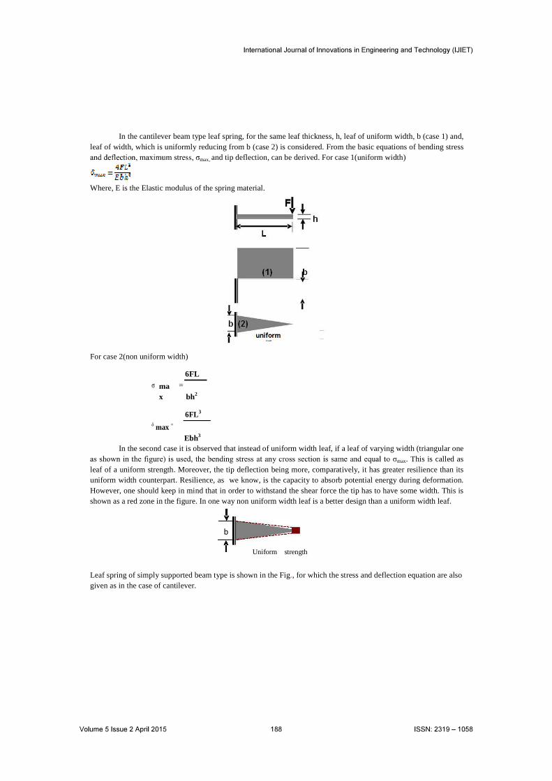
In the cantilever beam type leaf spring, for the same leaf thickness, h, leaf of uniform width, b (case 1) and, leaf of width, which is uniformly reducing from b (case 2) is considered. From the basic equations of bending stress
max, and tip deflection, can be derived. For case 1(uniform width)
Where, E is the Elastic modulus of the spring material.
For case 2(non uniform width)
=6FL
max bh2
max =6FL3
Ebh3
In the second case it is observed that instead of uniform width leaf, if a leaf of varying width (triangular one
max. This is called as leaf of a uniform strength. Moreover, the tip deflection being more, comparatively, it has greater resilience than its uniform width counterpart. Resilience, as we know, is the capacity to absorb potential energy during deformation. However, one should keep in mind that in order to withstand the shear force the tip has to have some width. This is shown as a red zone in the figure. In one way non uniform width leaf is a better design than a uniform width leaf.
Leaf spring of simply supported beam type is shown in the Fig., for which the stress and deflection equation are also given as in the case of cantilever.
b
Uniform strength
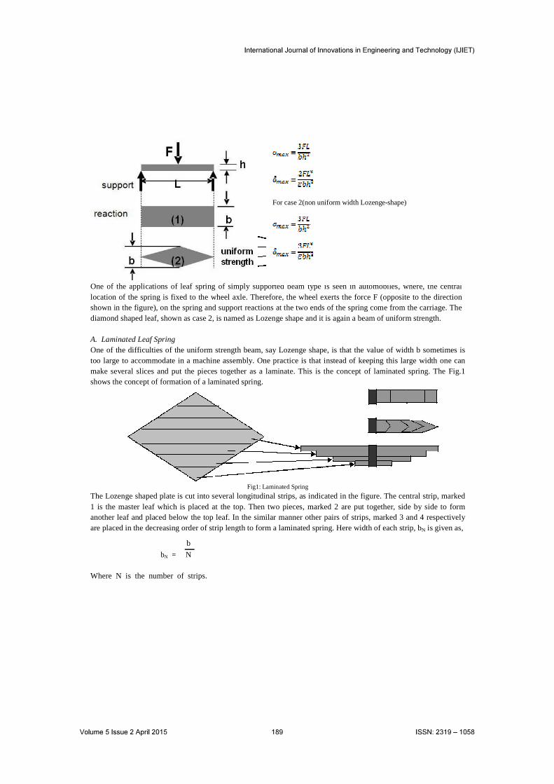
One of the applications of leaf spring of simply supported beam type is seen in automobiles, where, the central location of the spring is fixed to the wheel axle. Therefore, the wheel exerts the force F (opposite to the direction shown in the figure), on the spring and support reactions at the two ends of the spring come from the carriage. The diamond shaped leaf, shown as case 2, is named as Lozenge shape and it is again a beam of uniform strength.
A. Laminated Leaf SpringOne of the difficulties of the uniform strength beam, say Lozenge shape, is that the value of width b sometimes is too large to accommodate in a machine assembly. One practice is that instead of keeping this large width one can make several slices and put the pieces together as a laminate. This is the concept of laminated spring. The Fig.1shows the concept of formation of a laminated spring.
Fig1: Laminated Spring
The Lozenge shaped plate is cut into several longitudinal strips, as indicated in the figure. The central strip, marked 1 is the master leaf which is placed at the top. Then two pieces, marked 2 are put together, side by side to form another leaf and placed below the top leaf. In the similar manner other pairs of strips, marked 3 and 4 respectively are placed in the decreasing order of strip length to form a laminated spring. Here width of each strip, bN is given as,
bN =
b
N
Where N is the number of strips.
For case 2(non uniform width Lozenge-shape)

B. Laminated semi-elliptic spring
Fig 2: Laminated semi-elliptic spring
The Fig 2 shows a laminated semi- elliptic spring. The top leaf is known as the master leaf. The eye is provided for attaching the spring with another machine member. The amount of bend that is given to the spring from the central line, passing through the eyes, is known as camber. The camber is provided so that even at the maximum load the deflected spring should not touch the machine member to which it is attached. The camber shown in the figure is known as positive camber. The central clamp is required to hold the leaves of the spring. However, the bolt holes required to engage the bolts to clamp the leaves weaken the spring to some extent. Rebound clips help to share the load from the master leaf to the graduated leaf.
C. Materials for leaf springMaterials for leaf spring are not as good as that for the helical spring.Plain carbon steel, Chromium vanadium steel, Chromium- Nickel- Molybdenum steel, Silicon- manganese steel, are the typical materials that are used in the design of leaf springs.
D. Standard sizes of leaf springWidth (mm): 25-80 mm in steps of 5mmThickness (mm) : 2-8 mm in steps of 1mm, 10-16 mm in steps of 2mm
In order to carry heavy load few more additional full length leaves are placed below the master leaf for heavy loads. Such alteration from the standard laminated leaf spring, what we have learnt above, does not change the stress value, but deflection equation requires some correction.
max
=c qFL3
ENb Nh3
Where
=
1.0 4m + 2m 2 {1.5 ln(m)}
c (1.0 m)3
span 2L
eye camber
master leafcentral clamp
rebound clipgraduated leaves

where,
m = NN
f
Nf = Number of full length leavesN = Total number of leaves in the spring
III. STRESSES DUE TO SUPPORT HINGESThe master leaf of a laminated spring is hinged to the supports. The support forces induce, stresses due to longitudinal forces and stresses arising due to possible twist. Hence, the master leaf is more stressed compared to other the graduated leaves. Methods to reduce additional stresses could be,1. Master leaf is made of stronger material than the other leaves. 2. Master leaf is made thinner than the other leaves. This will reduce the bending stress as evident from stress
equation.3. Another common practice is to increase the radius of curvature of the master leaf than the next leaf. The last method is explained through Fig 3.
Initial bent created through fixing bolt during assembly
Fig 3. Nipping of leaf spring
The master leaf has a larger radius of curvature compared to the additional leaf that is placed below so obviously a gap will be created between the two leaves as indicated in the figure. Now, an initial bent is created during assembly by tightening the central bolt. Therefore, some amount of compressive stress will be produced at the inside curvature of the master leaf. Similarly, at the outside curvature of the master leaf tensile stress will be produced. Both these stresses are initial stresses in the master leaf. However, by such operation of tightening the central bolt, the additional leaf that is placed beneath the master leaf has a tendency to flatten out and as a result the stress pattern of the additional leaf will be reverse of that of the master leaf, tensile stress is produced at the inner curvature and compressive stress is produced at the outer curvature.
Hence, when the spring is loaded, for both the master leaf and the additional leaf, tensile stress will be produced at the inner curvature and compressive stress will be produced at the outer curvature. Therefore, due to opposite nature of initial stress and loading stress, the master leaf will experience lesser stress on both the surfaces. However, due to same nature of initial stress and loading stress, the additional leaf is stressed more compared to the master leaf. But, it is to be noted that the higher stress on the additional leaf is actually shared between all other leaves than the master leaf. This practice of stress relief in the master leaf is known as Nipping of leaf spring. As a matter of fact, all the leaves of a laminated leaf spring do have certain amount of nipping, so that there will be gaps between the leaves, as a result the stresses will be uniformly distributed and accumulated dusts can also be cleaned.
Larger radius
of curvature
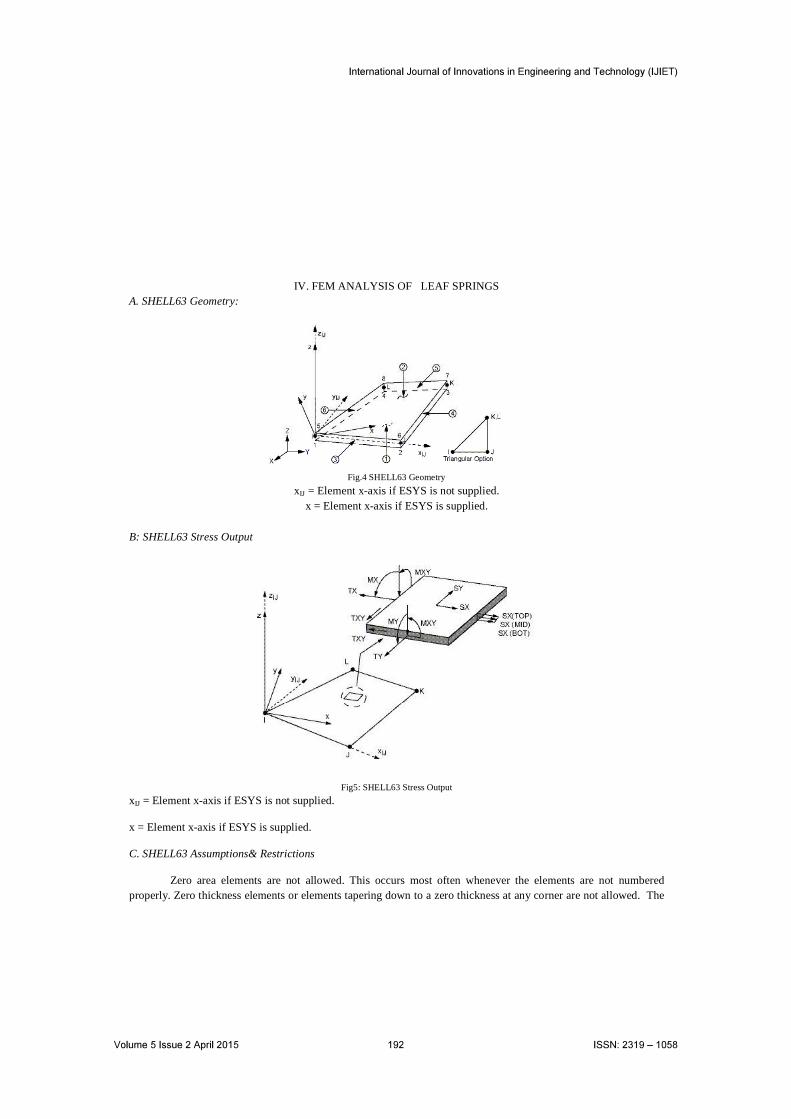
IV. FEM ANALYSIS OF LEAF SPRINGSA. SHELL63 Geometry:
Fig.4 SHELL63 Geometry
xIJ = Element x-axis if ESYS is not supplied.x = Element x-axis if ESYS is supplied.
B: SHELL63 Stress Output
Fig5: SHELL63 Stress Output
xIJ = Element x-axis if ESYS is not supplied.
x = Element x-axis if ESYS is supplied.
C. SHELL63 Assumptions& Restrictions
Zero area elements are not allowed. This occurs most often whenever the elements are not numbered properly. Zero thickness elements or elements tapering down to a zero thickness at any corner are not allowed. The
applied transverse thermal gradient is assumed to vary linearly through the thickness and vary bilinearly over the shell surface.
An assemblage of flat shell elements can produce a good approximation of a curved shell surface provided that each flat element does not extend over more than a 15° arc. If elastic foundation stiffness is input, one-fourth of the total is applied at each node. Shear deflection is not included in this thin-shell element. A triangular element may be formed by defining duplicate K and L node numbers as described in Triangle, Prism and Tetrahedral Elements. The extra shapes are automatically deleted for triangular elements so that the membrane stiffness reduces to a constant strain formulation.
D: Boundary conditions applied to mudguard model
Ø All degree of freedom of nodes around the holes has been constrained.
Ø Applied force in Z direction at the nodes on the edges of leaf springs at same position as actual.
V. RESULTS OF ANSYS
A. Loading on steel leaf
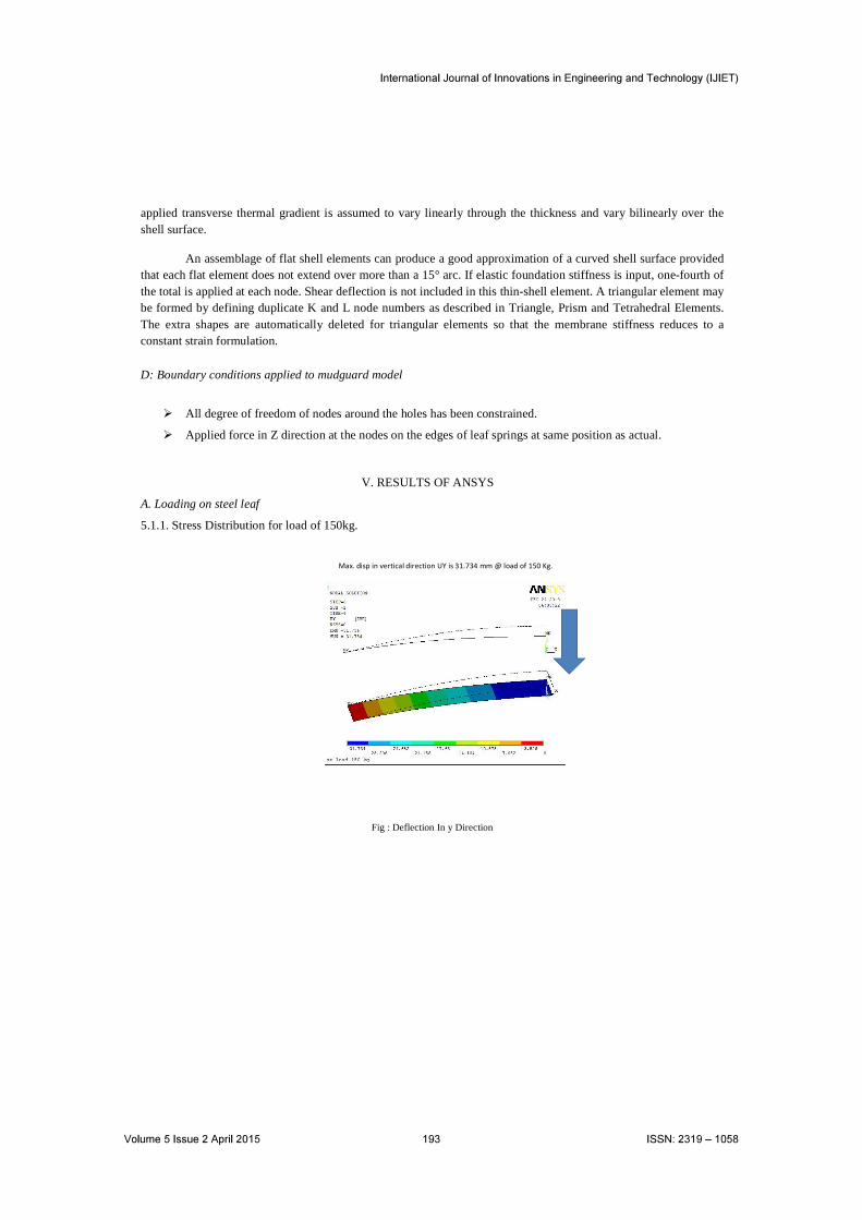
5.1.1. Stress Distribution for load of 150kg.
Max. disp in vertical direction UY is 31.734 mm @ load of 150 Kg.
Fig : Deflection In y Direction
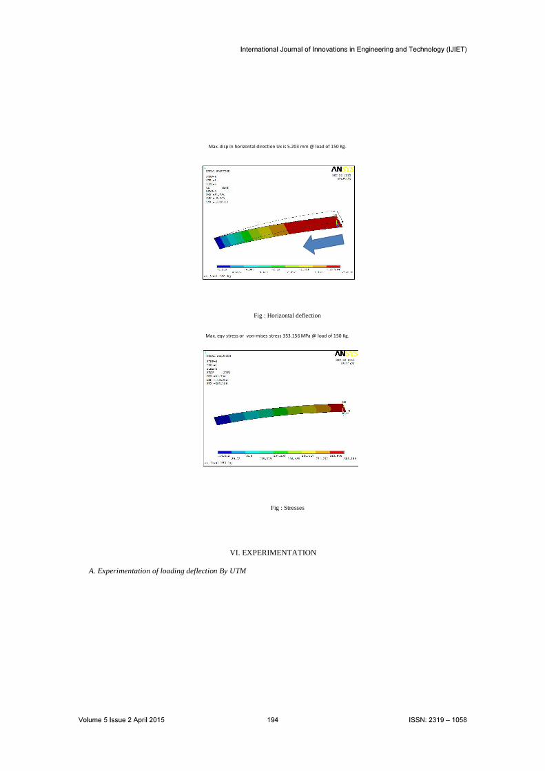
Max. disp in horizontal direction Ux is 5.203 mm @ load of 150 Kg.
Fig : Horizontal deflection
Max. eqv stress or von-mises stress 353.156 MPa @ load of 150 Kg.
Fig : Stresses
VI. EXPERIMENTATION
A. Experimentation of loading deflection By UTM
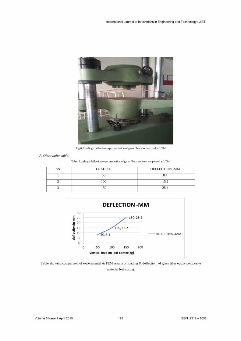
Fig 6: Loading / deflection experimentation of glass fiber specimen leaf at UTM
A. Observation table:
Table: Loading / deflection experimentation of glass fiber specimen sample rod at UTM.
SN LOAD KG DEFLECTION -MM
1 50 8.4
2 100 15.2
3 150 25.4
Table showing comparison of experimental & FEM results of loading & deflection of glass fiber epoxy composite
material leaf spring.
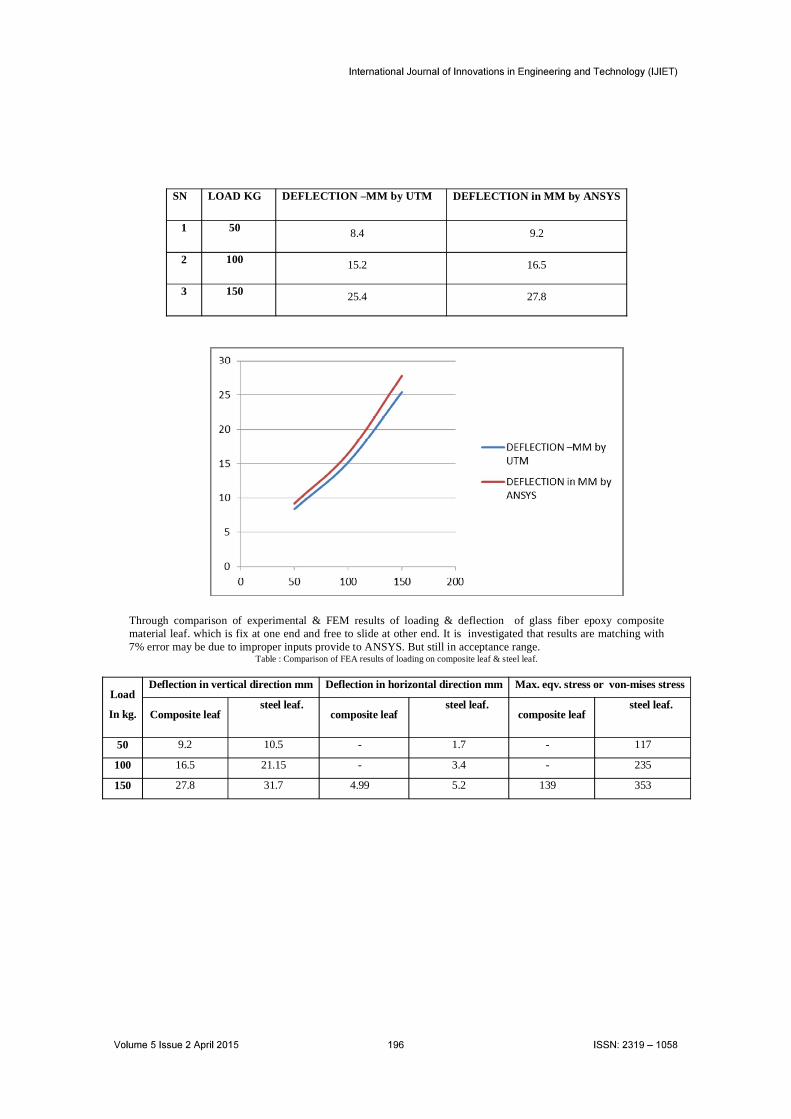
SN LOAD KG DEFLECTION –MM by UTM DEFLECTION in MM by ANSYS
1 50 8.4 9.2
2 100 15.2 16.5
3 150 25.4 27.8
Through comparison of experimental & FEM results of loading & deflection of glass fiber epoxy composite material leaf. which is fix at one end and free to slide at other end. It is investigated that results are matching with 7% error may be due to improper inputs provide to ANSYS. But still in acceptance range.
Table : Comparison of FEA results of loading on composite leaf & steel leaf.
Load
In kg.
Deflection in vertical direction mm Deflection in horizontal direction mm Max. eqv. stress or von-mises stress
Composite leafsteel leaf.
composite leafsteel leaf.
composite leafsteel leaf.
50 9.2 10.5 - 1.7 - 117
100 16.5 21.15 - 3.4 - 235
150 27.8 31.7 4.99 5.2 139 353
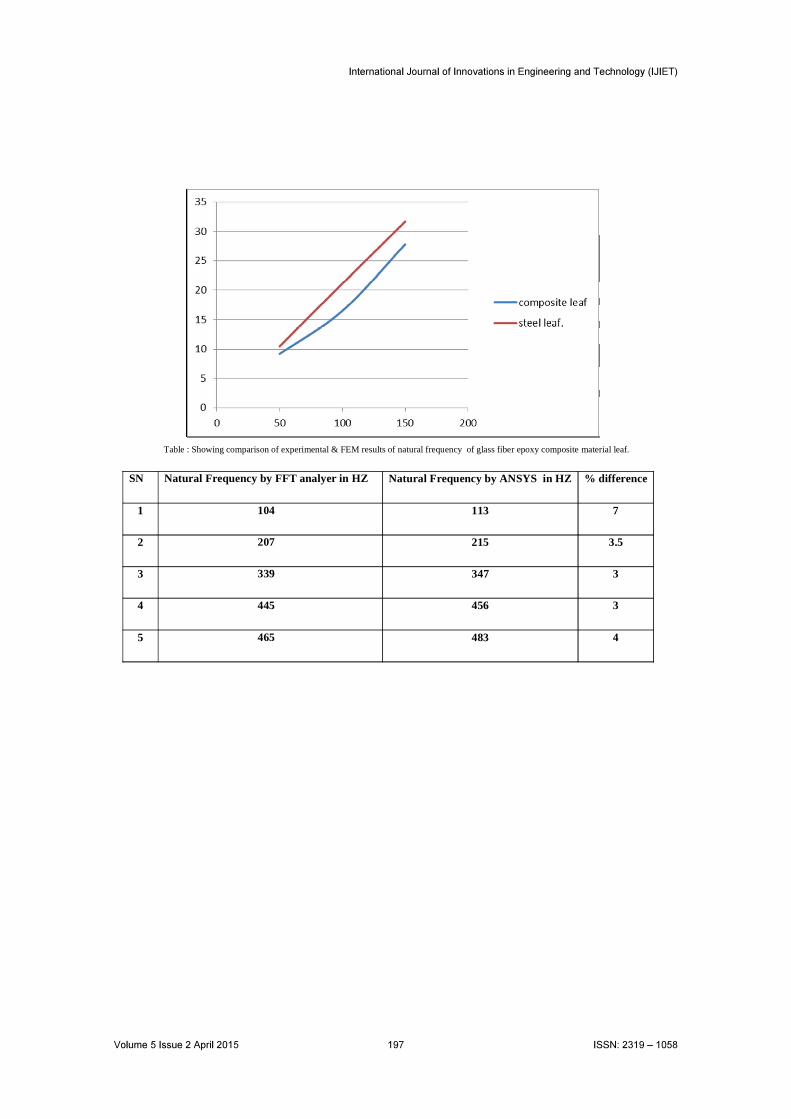
Table : Showing comparison of experimental & FEM results of natural frequency of glass fiber epoxy composite material leaf.
SN Natural Frequency by FFT analyer in HZ Natural Frequency by ANSYS in HZ % difference
1 104 113 7
2 207 215 3.5
3 339 347 3
4 445 456 3
5 465 483 4
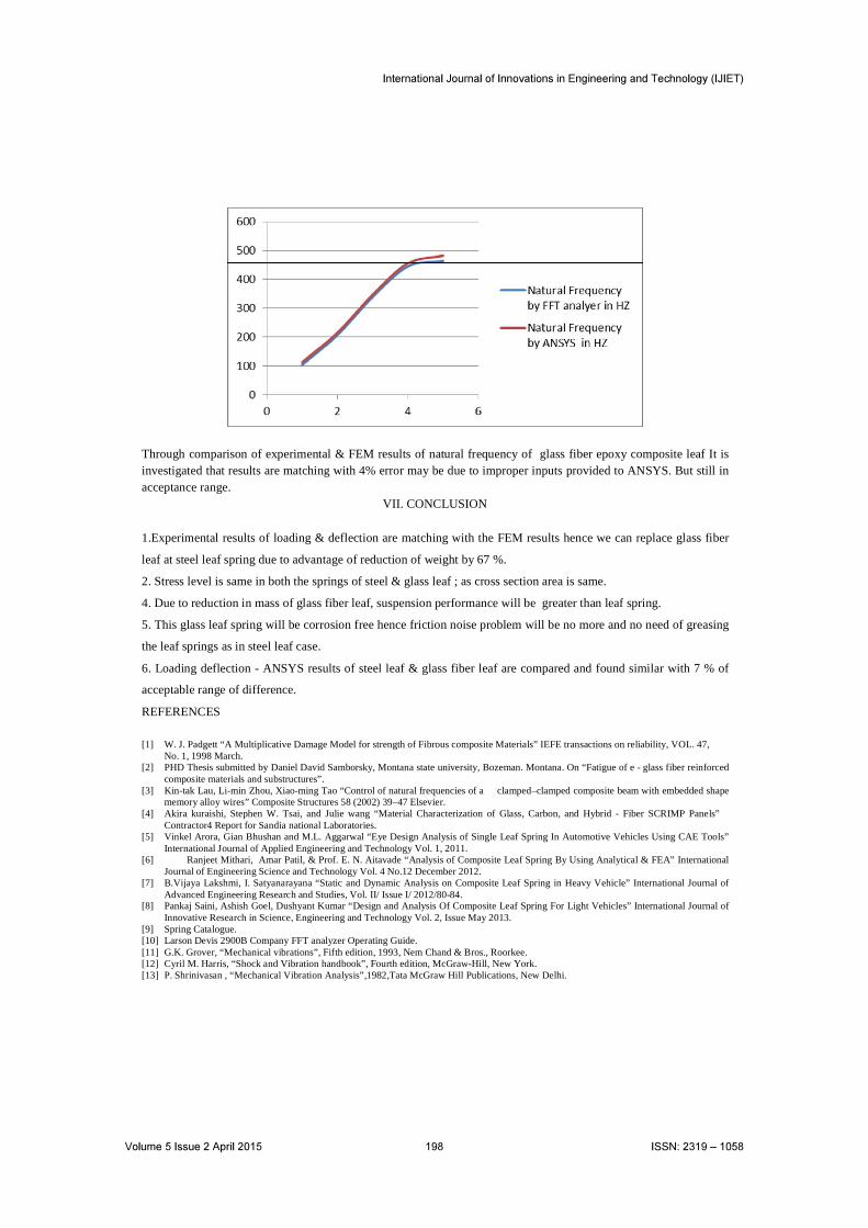
Through comparison of experimental & FEM results of natural frequency of glass fiber epoxy composite leaf It is investigated that results are matching with 4% error may be due to improper inputs provided to ANSYS. But still in acceptance range.
VII. CONCLUSION
1.Experimental results of loading & deflection are matching with the FEM results hence we can replace glass fiber
leaf at steel leaf spring due to advantage of reduction of weight by 67 %.
2. Stress level is same in both the springs of steel & glass leaf ; as cross section area is same.
4. Due to reduction in mass of glass fiber leaf, suspension performance will be greater than leaf spring.
5. This glass leaf spring will be corrosion free hence friction noise problem will be no more and no need of greasing
the leaf springs as in steel leaf case.
6. Loading deflection - ANSYS results of steel leaf & glass fiber leaf are compared and found similar with 7 % of
acceptable range of difference.
REFERENCES
[1] W. J. Padgett “A Multiplicative Damage Model for strength of Fibrous composite Materials” IEFE transactions on reliability, VOL. 47, No. 1, 1998 March.
[2] PHD Thesis submitted by Daniel David Samborsky, Montana state university, Bozeman. Montana. On “Fatigue of e - glass fiber reinforced composite materials and substructures”.
[3] Kin-tak Lau, Li-min Zhou, Xiao-ming Tao “Control of natural frequencies of a clamped–clamped composite beam with embedded shape memory alloy wires” Composite Structures 58 (2002) 39–47 Elsevier.
[4] Akira kuraishi, Stephen W. Tsai, and Julie wang “Material Characterization of Glass, Carbon, and Hybrid - Fiber SCRIMP Panels” Contractor4 Report for Sandia national Laboratories.
[5] Vinkel Arora, Gian Bhushan and M.L. Aggarwal “Eye Design Analysis of Single Leaf Spring In Automotive Vehicles Using CAE Tools” International Journal of Applied Engineering and Technology Vol. 1, 2011.
[6] Ranjeet Mithari, Amar Patil, & Prof. E. N. Aitavade “Analysis of Composite Leaf Spring By Using Analytical & FEA” International Journal of Engineering Science and Technology Vol. 4 No.12 December 2012.
[7] B.Vijaya Lakshmi, I. Satyanarayana “Static and Dynamic Analysis on Composite Leaf Spring in Heavy Vehicle” International Journal of Advanced Engineering Research and Studies, Vol. II/ Issue I/ 2012/80-84.
[8] Pankaj Saini, Ashish Goel, Dushyant Kumar “Design and Analysis Of Composite Leaf Spring For Light Vehicles” International Journal of Innovative Research in Science, Engineering and Technology Vol. 2, Issue May 2013.
[9] Spring Catalogue.[10] Larson Devis 2900B Company FFT analyzer Operating Guide.[11] G.K. Grover, “Mechanical vibrations”, Fifth edition, 1993, Nem Chand & Bros., Roorkee.[12] Cyril M. Harris, “Shock and Vibration handbook”, Fourth edition, McGraw-Hill, New York.[13] P. Shrinivasan , “Mechanical Vibration Analysis”,1982,Tata McGraw Hill Publications, New Delhi.