experimental analysis and modelling of an information ...vuir.vu.edu.au/1454/1/maung.pdf ·...
TRANSCRIPT

Experimental Analysis and Modelling of an
Information Embedded Power System
A Thesis
SUBMITTED IN FULFILMENT OF THE REQUIREMENTS FOR THE DEGREE OF
DOCTOR OF PHILOSOPY
By
Amanullah Maung Than Oo
To
School of Electrical Engineering
Faculty of Health, Engineering and Science
Victoria University Australia

Declaration of Originality
I, Amanullah Maung Than Oo, declare that the PhD thesis entitled ―Experimental
Analysis and Modelling of an Information Embedded Power System‖ is no more than
100,000 words in length, exclusive of tables, figures, appendices and references. This
thesis contains no material that has been submitted previously, in whole or in part, for
the award of any other academic degree or diploma. Except where otherwise indicated,
this thesis is my own work.
Amanullah Maung Than Oo

To my wonderful wife Habibah Begum
and
Our lovely son Midhad Aman

Abstract
Experimental Analysis and Modelling of an Information Embedded Power System
ii
ABSTRACT
As power industry enters the new century, powerful driving forces, uncertainties and
new functions are compelling electric utilities to make dramatic changes in their
information communication infrastructure. Expanding network services such as real time
measurement and monitoring are also driving the need for more bandwidth in the
communication network and reliable communication infrastructure. These needs will
grow further as new remote real-time protection and control applications become more
feasible and pervasive. Information embedded power system via wide area network
(IEPS-W) is the solution to accommodate the growing demand of wide area monitoring,
protection and control. IEPS-W is an extension of traditional power systems with added
monitoring, control and telecommunications facilities.
Various power system communication protocols are being used within IEPS-W to
transmit critical data in real time along with decades old Supervisory Control and Data
Acquisition System (SCADA). Most of the protocol in used are not originally developed
to use in wide area computer network (WACN) environment. However, protocol
developers upgrade their protocols and use it in WACN. This requires experimental
investigation of various power system communication protocols before employing it on
the power grid.
An experimental platform was set up at Victorian Network Switching Centre owned by
SP AusNet PTY LTD (an Australian Transmission and Distribution company based in

Abstract
Experimental Analysis and Modelling of an Information Embedded Power System
iii
Victoria) in order to experimentally analyse the performance characteristic of Distributed
Network Protocol (DNP3) over wide area network (WAN). In this experiment, real time
data were sent from Intelligent Electronic Devices to utility control center using WAN.
Experimental work reveal that measurement delays associated with DNP3 over WAN is
high, as this type of network is much more complex due to the added complexities of
routing and switching. This requires further development of DNP3 protocol to be reliably
used in IEPS-W. Hence, DNP3 was further developed using Optimized Network
Engineering Tools (OPNET). OPNET is the industry‘s leading simulator specialized for
network research and development. Finally, a new protocol has been developed based
on DNP3 protocol to reliably and securely transmit power system data for IEPS-W.

Acknowledgements
Experimental Analysis and Modelling of an Information Embedded Power System
iv
ACKNOWLEDGEMENTS
First and foremost, I would like to express my special appreciation to my supervisor
Professor Akhtar Kalam for his guidance, assistance and encouragement during this
research. The opportunities and learning experiences he has given me are deeply
appreciated. My experience at Victoria University is especially rewarding and helpful in
my future career because of his supports not only in the research work but also in many
other aspects. I would also like to show my appreciation to my co-supervisor for his
timely advice and support throughout this research.
I would like to thank SP AusNet PTY LTD for providing all the hardware and software
required for this project. In particular, I would like to thank Kevin Whelan, Andrew
Roberts and Doug Peddler for their cooperation and assistant. I also would like to thank
my colleagues at the School of Electrical Engineering for their valuable support. In
particular, I would like to thank Dr. Cagil Ozansoy, Hassan AL-Khalidi, Abdulrahman
Hadbah, David Fitrio, Adnand Mohan, Jaideep Chandran, Nikhil Joglekar and other
friends in room D706 and G218, School of Electrical Engineering. I would also like to
thank my parents, parents-in-law and other family members including Shafiqur Rahman,
Dr. Faridur Rahman and Aksa Jamila for their support and encouragement.
Above all, I would like to give special thanks and appreciations to my wonderful wife
Habibah Begum and my lovely son Midhad Aman for their love, patience,
understandings, scarifies and encouragements during this research.

List of Abbreviations
Experimental Analysis and Modelling of an Information Embedded Power System
v
LIST OF ABBREVIATIONS
ACSI Abstract Communication Service Interface
AGC Automatic Generation Control
ALP Application Layer Protocol
ATM Asynchronous Transfer Mode
CASM Common Application Service Models
CORBA Common Object Request Broker Architecture
CRC Cyclic Redundancy Code
CSMA/CD Carrier Sense Multiple Access/Collision Detection
DA Destination Address
DCOM Distributed Component Object Model
DES Data Encryption Standard
DMS Distributed Management System
DNP3 Distributed Network Protocol version 3
DPU Data Processing Unit
DTS Dispatcher Training Simulator
EMS Energy Management Systems
EPRI Electric Power Research Institute
FACTS Flexible AC Transmission System
GOMSFE Generic Object Models for Substation and Feeder Equipment
GOOSE Generic Object-Oriented Substation Events

List of Abbreviations
Experimental Analysis and Modelling of an Information Embedded Power System
vi
ICCP Inter-control Centre Communications Protocol
ICV Integrity Check Value
IEC International Electrotechnical Commission
IEDs Intelligent Electronic Devices
IEEE Institute of Electrical and Electronics Engineers
IEPS-W Information Embedded Power System over Wide Area Network
IETF Internet Engineering Task Force
IIN Internal Indications
IKE Internet Key Exchange
IP Internet Protocol
IPSec Internet Protocol Security
IT Information Technology
LAN Local Area Network
LPDU Link Protocol Data Unit
LSDU Link Service Data Unit
MMS Manufacturing Message Specification
MTU Master Terminal Units
NIS Network Integrated System
NTP Network Time Protocol
OO Object Oriented
OPNET Optimised Network Engineering Tools
OSI Open Systems Interconnection
PGP Pretty Good Privacy

List of Abbreviations
Experimental Analysis and Modelling of an Information Embedded Power System
vii
PKI Public Key Infrastructure
PLC Power Line Carrier
PSTN Public Switched Telephone Networks
PVC Permanent Virtual Circuit
RTS Richmond Terminal Station
RTU Remote Terminal Unit
SA Substation Automation
SCADA Supervisory Control and Data Acquisition System
SCSM Specific Communication Service Mapping
SDU Service Data Unit
SEL Schweitzer Engineering Laboratories
SNMP Simple Network Management Protocol
SONET Synchronous Optical Network
SSL/TLS Secure Sockets Layer / Transport Layer Security
SVC Switched Virtual Circuit
TCP/IP Transmission Control Protocol/Internet Protocol
TH Transport layer Header
TPCI Transport Protocol Control Information
TPDU Transport Protocol Data Unit
TSDU Transport Service Data Unit
UCA Utility Communication Architecture
UDP User Datagram Protocol
UDP/IP User Datagram Protocol/Internet Protocol

List of Abbreviations
Experimental Analysis and Modelling of an Information Embedded Power System
viii
VHF/UHF Very High Frequency / Ultra High Frequency
VNSC Victoria Network Switching Centre
VOIP Voice Over Internet Protocol
VON Virtual Overlay Network
VPN Virtual Private Network
WAN Wide Area Network
WACN Wide Area Computer Network XML Extensible Markup Language

Table of Contents
Experimental Analysis and Modelling of an Information Embedded Power System
ix
TABLE OF CONTENTS
ABSTRACT ii
ACKNOWLEDGEMENTS iv
LIST OF ABBREVIATIONS v
TABLE OF CONTENTS ix
LIST OF FIGURES xiv
LIST OF TABLES xvii
LIST OF PUBLICATIONS xviii
CHAPTER 1 THESIS OVERVIEW
1.0 Introduction 1
1.1 Motivation 4
1.2 Research methodologies and techniques 6
1.3 Organization of the Thesis 9
1.4 Originality of the Thesis 11
CHAPTER 2 LITERATURE REVIEW
2.0 Introduction 13
2.1 Wide area power system monitoring, protection and control 15
2.1.1 Impact of the information technology on power system 16
2.1.2 Obstacles to technology 21
2.1.3 Possible solutions to technology obstacles 27
2.2 Deregulated utility communication requirements 33

Table of Contents
Experimental Analysis and Modelling of an Information Embedded Power System
x
2.2.1 Importance of real time information in power system 41
2.2.2 Future power system information needs 44
2.3 Current power system data communication media 45
2.4 Power system communication protocols 48
2.5 SCADA system design for electric utilities 53
2.6 Conclusion 56
CHAPTER 3 AN OVERVIEW OF MODERN INFORMATION EMBEDDED POWER
SYSTEMS
3.0 Introduction 58
3.1 Information embedded power system 59
3.1.1 Measurement system 59
3.1.2 Communication system 62
3.1.3 Energy control centre 64
3.2 Power system communication protocols 68
3.2.1 Distributed Network Protocol (DNP3) 68
3.2.2 IEC 61850 76
3.2.3 Other commonly used power system communication protocols 79
3.3 Conclusion 82
CHAPTER 4 EXPERIMEN TAL ANALYSIS OF DNP3 PROTOCOL FOR AN IEPS-W
4.0 Introduction 83
4.1 Experimental setup 84

Table of Contents
Experimental Analysis and Modelling of an Information Embedded Power System
xi
4.2 Experimental procedures 89
4.3 Experimental results 93
4.4 Conclusion 101
CHAPTER 5 MODELLING OF DNP3 PROTOCOL FOR AN IEPS-W
5.0 Introduction 102
5.1 Brief overview of OPNET modeller 103
5.2 Development and modelling of DNP3 protocol using OPNET modeller 104
5.2.1 Implementation of DNP3 data link layer 107
5.2.2 Implementation of DNP3 transport layer 110
5.3 Development and implementation of DNP3 Application Layer 116
5.3.1 Message structure 118
5.3.2 Fragment rules 125
5.3.3 Classes 128
5.3.4 Time synchronisation 129
5.3.5 Level 1 Implementation 130
5.3.6 Implementation of DNP3 application layer 136
5.3.7 Master solicited response reception state 148
5.4 Conclusion 153
CHAPTER 6 MODELLING OF AN EFFICIENT INFORMATION EMBEDDED POWER
SYSTEM
6.0 Introduction 154

Table of Contents
Experimental Analysis and Modelling of an Information Embedded Power System
xii
6.1 Importance of time critical communication infrastructure 156
for power system
6.2 Development and modelling of efficient IEPS – W 157
6.2.1 Implementation of unsolicited response for IEPS-W 158
6.2.2 Master unsolicited response reception state table 178
6.3 Conclusion 184
CHAPTER 7 MODELLING OF SECURE INFORMATION EMBEDDED POWER
SYSTEM
7.0 Introduction 185
7.1 Secure communication system for utilities 185
7.1.1 Threats analysis of DNP3 protocol 187
7.1.2 SCADA securities issues 191
7.1.3 Approaches to enhance IEPS – W security 192
7.2 Development and implementation of DNPSec for IEPS – W 201
7.2.1 DNP3 security framework 201
7.2.2 Key management 206
7.2.3 Analysis of the approach 208
7.2.4 SCADA/DNP3 over IP 210
7.2.5 Implementation of DNPSec in IEPS – W 212
7.3 Conclusion 219
CHAPTER 8 CONCLUSIONS AND FUTURE WORK

Table of Contents
Experimental Analysis and Modelling of an Information Embedded Power System
xiii
8.1 Introduction 221
8.2 Summary and achievements of the research 223
8.3 Future work 226
REFERENCES 229
APPENDIX
A. Experimental data for DNP3 251
B. Detailed function code procedures 276

List of Figures
Experimental Analysis and Modelling of an Information Embedded Power System
xiv
LIST OF FIGURES
Figure 1.1: Information embedded power system over WAN (IEPS-W) 1
Figure 2 .1: Substation communication protocols [38] 26
Figure 2.2: SCIMS - base architecture [46] 33
Figure 2.3: Computer network controlling the electric network 36
with a tree topology [49]
Figure 2.4: Integrated WAN communication network [50] 38
Figure 2.5: The circle of measurement, information and decision making 42
Figure 2.6: Future power system information needs 45
Figure 2.7: The OSI reference model 50
Figure 2.8: The Ethernet network concept [80] 51
Figure 2.9: TCP/IP protocols and functional layers [26] 52
Figure 2.10: RTU components [91] 55
Figure 3.1: Energy control centre [103] 65
Figure 3.2: DNP3 common system architecture [105] 70
Figure 3.3: Client and server relationship [105] 71
Figure 3.4: DNP3 frame 72
Figure 3.5: DNP3 protocol stack [105] 75
Figure 3.6: Network topology [105] 76
Figure 3.7 ACSI Conceptual model 78
Figure 3.8 Three levels of UCA [113] 80
Figure 4.1: Experimental set-up 86

List of Figures
Experimental Analysis and Modelling of an Information Embedded Power System
xv
Figure 4.2: Control room (master) and slaves (RTUs) setting 89
Figure 4.3: Time interval setting 90
Figure 4.4: Time setting up to milliseconds 90
Figure 4.5: DNP3 classes 91
Figure 4.6: ASE2000 communication test set: TCP as transport mode 92
Figure 4.7: Activity timeline for DNP3-LAN/WAN (TCP/IP) 92
Figure 4.8: Propagation delay with 10% data traffic in DNP3-WAN (TCP/IP) 94
Figure 4.9: Propagation delay in DNP3-WAN (TCP/IP) with 20% traffic increase 96
Figure 4.10: Propagation delay in DNP3-WAN (TCP/IP) with 40 % traffic increase 97
Figure 4.11: Propagation delay in DNP3-WAN (TCP/IP) with 60 % traffic increase 98
Figure 4.12: Propagation delay in DNP3-WAN (TCP/IP) with 80 % traffic increase 99
Figure 4.13: Mean propagation delay for DNP3-WAN (TCP/IP) 100
Figure 5.1: DNP3 protocol stack [105] 104
Figure 5.2: Control centre and IED in OPNET platform 105
Figure 5.3: DNP3 protocol stack in OPNET environment 106
Figure 5.4: DNP3 data link layer in OPNET environment 110
Figure 5.5: Transport layer message layout 113
Figure 5.6: TH Bit definitions 113
Figure 5.7: Transmission of a single frame message 115
Figure 5.8: DNP3 transport lawyer in OPNET platform 115
Figure 5.9: DNP3 device interface 116
Figure 5.10: Message sequence 117
Figure 5.11: Application request header 118

List of Figures
Experimental Analysis and Modelling of an Information Embedded Power System
xvi
Figure 5.12: Application response header 119
Figure 5.13 Application control fields 119
Figure 5.14: Outstation fragment state diagram 146
Figure 5.15: Outstation fragment state diagram in OPNET environment 147
Figure 5.16: Master solicited response reception diagram 152
Figure 5.17: Master solicited response reception diagram in OPNET 153
Figure 6.1: Unsolicited timing diagram 159
Figure 6.2: Ideal mixed unsolicited and solicited communications 169
Figure 6.3: Unsolicited response or confirmation not received 170
Figure 6.4: Read request received in region A 172
Figure 6.5: Read request received in region A (2) 174
Figure 6.6: Read request received in period B (1) 176
Figure 6.7: Read request received in period B (2) 177
Figure 6.8: Master unsolicited response reception diagram 179
Figure 6.9: Master unsolicited response in OPNET platform 181
Figure 6.10 IEPS-W in OPNET environment 182
Figure 6.11: Mean propagation delay of efficient IEPS-W 183
Figure 7.1: Planning the attack 189
Figure 7.2 DNPSec protocol structure 203
Figure 7.3: DNPSec request / respond link communication 207

List of Tables
Experimental Analysis and Modelling of an Information Embedded Power System
xvii
LIST OF TABLES
Table 4.1: Summary of experimental features and characteristics 85
involved in DNP3-WAN (TCP/IP) experiment
Table 4.2: Propagation delay with 10% data traffic 94
Table 4.3: Propagation delay with 20% increased data traffic 95
Table 4.4: Propagation delay with 40% increased data traffic 96
Table 4.5: Propagation delay with 60 % increased data traffic 97
Table 4.6: Propagation delay with 80 % increased data traffic 99
Table 4.7: Summary of experimental results in different network traffic 100
Table 5.1: Function code table 120
Table 5.2: Level 1 Implementation (DNP-L1) 133
Table 5.3: Outstation fragment state table 138
Table 5.4: Master reception state table, solicited responses 150
Table 6.1: Master reception state table, unsolicited responses 180
Table 7.1: Dynamic behaviour and relative performance characteristics of 209
large scale VPN environments
Table 7.2: Advantages and disadvantages of DNPSec 210
(proposed solution), DNP3/IPSec and DNP3/SSL/TLS architectures
Table 7.3: The performance of DNPSec implementation in IEPS-W model 218

List of Publications
Experimental Analysis and Modelling of an Information Embedded Power System
xviii
LIST OF PUBLICATIONS
Journals
1. Amanullah M.T.O, Kalam A. and Zayegh A., ―Information Embedded Power
System: The effects of 'larger switched computer network' on the controllability of
power system,‖ Journal of the Australian Institute of Energy, March 2005,
Australia
2. Amanullah M.T.O, Kalam A. and Zayegh A., ―Wide area power system
monitoring, protection and control,‖ Association for the Advancement of
Modelling and Simulation Techniques in Enterprises (AMSE), France, 2006
3. Amanullah M.T.O, Kalam A. and Zayegh A., ―The effects of computer network on
the controllability of an information embedded power system,‖ Journal of
Information and Communication Technology, Vol. 1, No. 1, (Summer 2005) pp:
29-35, TECNOLOGICS
4. Amanullah M.T.O, Kalam A. and Zayegh A., ―Power System Communications
Review: Data Communications Requirement in a Deregulated Environment,‖
Australian Journal of Electrical & Electronics Engineering, 07. ( Accepted for
publication)

List of Publications
Experimental Analysis and Modelling of an Information Embedded Power System
xix
Conference papers
1. Amanullah M.T.O, Kalam A. and Zayegh A., ―Information embedded power
system: the effective communication system of the 21st century power system
industry,” AUPEC 04, September 26-29, Brisbane, Australia.
2. Amanullah M.T.O, Kalam A. and Zayegh A., ―Effective power system
communication requirements for deregulated power industry,‖ APCCAS 04,
December 6-9, Tainan, Taiwan.
3. Mahajan M.M, Amanullah M.T.O and Kalam A., ―Renewable hydrogen based
distributed power generation systems,‖ ICECE 04, December 28-30, Dhaka,
Bangladesh.
4. Amanullah M.T.O, Kalam A. and Zayegh A., ―Network Security Vulnerabilities in
SCADA and EMS,‖ IEEE/PES T&D 2005 Asia Pacific, August 14-18, 2005,
Dalian, China.
5. Amanullah M.T.O, Kalam A. and Zayegh A., ―Communication in power system:
Time to use information embedded power system in developing countries for
efficient transmission of power system data,‖ ROVISP 2005: International
Conference on Robotics, Vision, Information and Signal processing, 20-22 July
2005, Penang, Malaysia.

List of Publications
Experimental Analysis and Modelling of an Information Embedded Power System
xx
6. Mahajan M.M, Amanullah M.T.O and Kalam A., ―Soft start and solid state speed
control of a D.C. shunt drive,‖ ROVISP 2005: International Conference on
Robotics, Vision, Information and Signal processing, 20-22 July 2005, Penang,
Malaysia.
7. Amanullah M.T.O, Kalam A. and Zayegh A., ―Fiber Optic Network Infrastructure
as next generation power system communications‖, The 6th Jordanian
International Electrical & Electronics Engineering Conference, JIEEEEC 2005,
November 15-17, 2005,Amman, Jordan.
8. Amanullah M.T.O, Kalam A. and Zayegh A., ―Power system communication
laboratory,” AUPEC 05, 25th - 28th September 2005, Hobart, Tasmania,
Australia.
9. Amanullah M.T.O, Kalam A. and Zayegh A., ―Wide area power system
monitoring, protection and control,‖ International Conference on Modelling and
Simulation Marrakesh, Morocco, 22- 24 November 2005.
10. Amanullah M.T.O, Kalam A. and Zayegh A., ―Experimental analysis and
modelling of an information embedded power system,” AUPEC 05, 25th - 28th
September 2005, Hobart, Tasmania, Australia.

List of Publications
Experimental Analysis and Modelling of an Information Embedded Power System
xxi
11. Amanullah M.T.O, Kalam A. and Zayegh A., ―Intelligent control and protection of
power system with IEPS-W,‖ 8th International Conference on AC and DC power
transmission, 28-31 March 2006, London, United Kingdom.
12. Amanullah M.T.O, Kalam A. and Zayegh A., ―Development of information
embedded power system using OPNET,” AUPEC 06, 10-13 December 06,
Melbourne, Australia.
13. M.T.O Amanullah, Md Mainuddin, H. Md Safayat, A. Kalam, A. Zayegh,
―Development of Real Life Power System Communication and Protection
Laboratory At Victoria University,” AUPEC 06, 10-13 December 06, Melbourne,
Australia.
14. Amanullah M.T.O, Kalam A. and Zayegh A., ―Experimental Investigations of
DNP3 Protocol for an Information Embedded Power System,” IASTED, PES
2007, USA.
15. Amanullah M.T.O, Kalam A. and Zayegh A., ―Performance Analysis of Power
System Communication Protocols for an Information Embedded Power System,‖
Oman, International Conference on Communication, Computer and Power
(ICCCP'07), February 19 to 21, 2007, Sultanate of Oman.

List of Publications
Experimental Analysis and Modelling of an Information Embedded Power System
xxii
16. Al-Khalidi H., Kalam A, Amanullah M.T.O., ―Investigation of aging devices in
power network‖ AUPEC 06, 10-13 December 06, Melbourne, Australia.

Chapter 1: Thesis Overview
Experimental Analysis and Modelling of an Information Embedded Power System
1
CHAPTER 1
THESIS OVERVIEW
1.0 Introduction
An Information Embedded Power System over wide area network (IEPS-W) is an
extension of traditional power systems with added monitoring, control and
telecommunication capabilities. In this thesis, information embedded power system
refers to transmitting power system data from various Intelligent Electronic Devices
(IEDs) or Remote Terminal Units (RTU) to the control centre using Distributed Network
Protocol (DNP3) over Wide Area Network (WAN). A simplified illustration of an IEPS-W
is shown in Figure 1.1.
Figure 1.1: Information embedded power system over WAN (IEPS-W)

Chapter 1: Thesis Overview
Experimental Analysis and Modelling of an Information Embedded Power System
2
As seen in the figure, IEPS-W consists of: i) power system hardware ii) the
measurement system – which is represented by IEDs or RTUs iii) the communication
system representing WAN and iv) the electric utility control centre. In this system, IEDs
or RTUs record power system measurements and send them in real time over a wide
area computer network to the power control centre using DNP3 protocol. Control
centres also send control messages to various IEDs to perform control actions such as
opening/closing breakers, relays actions, transformer tap changing and generation
control. This thesis investigates the performance accuracy and characteristics of the
DNP3 protocol over WAN when data are being sent from IEDs to control room.
Various power system monitoring and observability method has been discussed in
references [1-12]. Power utility uses different power system communication protocols to
transmit data from field devices to control centre using dedicated proprietary link.
Recently, with the advancement of information and communication technology, utility
utilizes computer network technology to transmit power system data. However, little
research is available showing investigation whether any investigation involving the
existing power system protocols are able to deliver the service requirements when
power system employs existing protocols over computer network especially over WAN.
This thesis is a pioneering step in attempting to investigate the propagation delays
associated in DNP3 protocols when power system data are being sent over WAN.
Higher propagation delays in the power network due to propagation delay may render
parts of the power system unobservable and uncontrollable.

Chapter 1: Thesis Overview
Experimental Analysis and Modelling of an Information Embedded Power System
3
Due to increasing demand of data by various utility, research efforts have begun to
make power system communication infrastructure more efficient, reliable and secure.
Further research has also been focused on how delays in computer control networks
can introduce errors in measurements, when these measurements are sent across the
wide area network. Carullo has done a thorough experimental study on measurement
delay errors while power system employs local area network (LAN) to transmit power
system data [13].
A Matlab simulation study was performed by Lian, Moyne and Tilbury [14] to determine
key performance parameters of several types of common direct-link computer networks.
These parameters included network utilization, magnitude of expected time delay and
characteristics of time delays. Skeie, Johannessen and Brunner [15] investigated
whether Ethernet has sufficient performance characteristics to meet real-time demands
of substation automation. Luque, Escudero and Perez [16] also develop an analytical
model of the relationship between measurement error and delay. They modelled the
evolution of magnitudes in electric networks as a first order autoregressive process
AR(1). This model assumes measurement error is a function of both the
communications delay and the bandwidth of the evolution of the voltage magnitude.
Section 1.2 provides some motivation on the requirement of the performance analysis of
currently available power system communication protocols. Research methodologies
and techniques are discussed in Section 1.3. Organization of the thesis is presented in
Section 1.4. Section 1.5 highlights originality of the thesis.

Chapter 1: Thesis Overview
Experimental Analysis and Modelling of an Information Embedded Power System
4
1.1 Motivation
Information exchange is a vital component in the efficient operation, profitability and
growth of a restructuring electric power industry. Commercial and regulatory needs
today mandate a variety of advanced utility functions [13], including:
Real-time calculation/optimisation of total/available transmission and
generation
Contingency assessment and response using live data to feed wide-area
protection and islanding algorithms
Asset and workforce management with constantly updated databases
Spot market/power exchange energy pricing and delivery
Demand response, energy efficiency, and customer management through
real time pricing, advanced metering and distributed generation
Outage management, auto-restoration and distribution network
optimisation based on up-to-the-minute data from customer premises.
Integrated information systems and telecommunications networks capable of supporting
these functions, as well as future capabilities, are critical in the changing utility
environment.
Key to facilitating this exchange is adherence to industry standards and specifications
and utilisation of established protocols in the design, implementation and operation of
electric power and communication systems. For a utility to deploy and maintain an open

Chapter 1: Thesis Overview
Experimental Analysis and Modelling of an Information Embedded Power System
5
and interoperable communications and control environment, standards must shape the
architecture and accepted practices of the entire enterprise, especially when it is
required to integrate different systems, vendors and technologies.
To improve the efficiency of a power system, it is necessary to develop power system
monitoring devices and the system which can integrate and analyse the data from the
devices. The system having the function to control the power system property is
important, where the data collected with the device will be used as a control input. It is
expected that there will be many of communication activities between the devices and
the system. Thus designing the efficient communication protocol is very important. For
this reason, it is vital that the performance of existing power system communication
protocols is experimentally analysed. For example, the distribution of packet delivery
times under different network traffic using different protocols may have a large effect on
the real-time state estimation solvability or cause unacceptable error magnitudes.
Random network traffic may cause delays in delivering metered data to the state
estimator in the control centre, which may render many buses in a power system
unobservable during one or more calculation intervals [14].
The modern trends towards implementing computer networks for transmitting power
system measurements to the power system control centre, have provided a motivation
for studying the performance of different protocols when employed in WAN. Up until
now, little research has been carried out to experimentally investigate performance
analysis of various available power system communication protocols. Furthermore, little

Chapter 1: Thesis Overview
Experimental Analysis and Modelling of an Information Embedded Power System
6
research has been done to analyse how random measurement delays due to WAN
traffic can affect the accuracy of power system measurements. Hence, experimental
investigation is required to systematically analyse performance characteristic of different
power system communication protocols before adopting them into WAN environment.
1.2 Research methodologies and techniques
This research aims to experimentally study the performance of DNP3 protocol over
WAN when data are sent from various IEDs to power control centre. The main aim is to
develop an efficient power system communication protocol based on DNP3 for an
information embedded power system to significantly reduce the propagation delay
associated with DNP3. The experimentation was done using real life power system
hardware, tools and software own by SP AusNet (a Australian Transmission and
Distribution Organisation based in Victoria). Modelling, design, implementation,
simulation and development was carried out using appropriate software development
and network design tools called Optimized Network Engineering Tools (OPNET). The
details of proposed methodology and techniques to achieve the requirements of this
research project are as follows:
1.2.1 Analysis of the currently available systems / Literature review
This initial stage of the research program involved searching the state of art in the field
of power system monitoring, control and protection by analysing the currently available

Chapter 1: Thesis Overview
Experimental Analysis and Modelling of an Information Embedded Power System
7
systems in order to recognize the weaknesses of the present power system
communications protocols which are used in the utility. This step of analysis and
research showed that up until now, little research has been performed to experimentally
investigate power system communication protocols such as DNP3 when power system
data are sent via WAN for efficiently and reliably transmitting power system data for
monitoring, control and protection purposes.
1.2.2 Setting-up experimental platform
An experimental platform was set up at Victorian Network Switching Centre owned by
SP AusNet Pty LTD in order to experimentally analyse the performance characteristic of
DNP3 protocol over WAN when data are sent from IEDs to utility control centre using
WAN. More specifically, the experiment was setup to experimentally measure the
propagation delay associated with DNP3 over WAN. The experimental platform consists
of power system hardware, measurement system, embedded computer network
communication system (WAN) and power system control centre as shown in Figure 1.1.
After experimental platform had been set up, power system data were sent from IEDs to
control center via WAN using DNP3 protocol and r the propagation delay recorded. The
experimental platform utilises TEKRON precision clock to accommodate the precision
timing.
1.2.3 Development and implementation of DNP3 link and transport layer modules

Chapter 1: Thesis Overview
Experimental Analysis and Modelling of an Information Embedded Power System
8
The measurement delays associated with wide area network was very high as this type
of network is much more complex due to the added complexities of routing and
switching. Hence, based on the experimental data collected and carefully investigating
the data, a more efficient and reliable protocol is developed based on DNP3 protocol
using OPNET modeller. DNP3 link and transport layer was initially developed to analyse
the protocol.
1.2.4 Design and implementation of DNP3 application layer modules
Application layer of DNP3 protocol is vital for critical data communication process. It
describes the message format, service and procedures. The application layer responds
to complete messages received (and passed up from the transport layer) and builds
messages based on the need for or the availability of user data. Once messages are
built, they are passed down to the pseudo-transport layer where they are segmented
and passed to the data link layer and eventually communicated over the physical layer.
After successfully developing the DNP3 link and transport layer, application layer was
developed using OPNET technology to fully investigate and simulate the measurement
delays involved in DNP3 over WAN.
1.2.5 Development of time efficient information embedded power system
A more reliable and time efficient power system communication is required in order to
transmit power system data more reliable and efficiently. After successfully developing

Chapter 1: Thesis Overview
Experimental Analysis and Modelling of an Information Embedded Power System
9
DNP3 in OPNET environment, a more reliable and time efficient IEPS-W has been
developed reducing the propagation delay involved in DNP3 over WAN. This allows
provide power system to monitor, control and protect more efficiently.
1.2.6 Development of secure information embedded power system
Modern power utility faces significant security threat when they employ internet
technology to transmit the power system critical and non-critical data. A more secure
and reliable communication system is essential to avoid catastrophic disaster from
major information attack. Hence, a more secure and reliable information embedded
power system has been developed for the modern utility based on DNP3 protocol for
IEPS-W.
1.3 Organization of the Thesis
This thesis contains eight chapters and is organized as follows:
Chapter 1 provides basic introduction about the research as well as the motivation
behind this research. This chapter also includes the research methodologies and
techniques and the contribution of this research to the knowledge of science and
engineering.

Chapter 1: Thesis Overview
Experimental Analysis and Modelling of an Information Embedded Power System
10
Chapter 2 presents literature review of power system communications, recent
developments and the use of protocols and future power system information needs. It
further discusses the power system communication requirements in deregulated power
industry highlighting the importance of efficient communication requirement in the
deregulated power industry.
An overview of information embedded power system over wide area network has been
presented in Chapter 3. It also details discussion on power system communication
protocols and wide area computer network together with an overview of energy control
centre. Chapter 4 presents detailed experimental analysis of DNP3 protocol over WAN
for an IEPS-W. It includes detailed experimental set up and procedure carried out to
investigate performance of DNP3. Experimental results and data have also been
included.
Chapter 5 presents modelling of information embedded power system. A brief overview
of OPNET modeller which was used for simulation, design and development of DNP3
protocol has been discussed. The design and implementation details of each layer of
DNP3 have been presented. Chapter 6 elaborates on the development of time efficient
information embedded power system together with requirement of time critical
infrastructure for power system. The implementation and development of secure
information embedded power system is presented in Chapter 7. The conclusions and
future scope for this research are discussed in Chapter 8.

Chapter 1: Thesis Overview
Experimental Analysis and Modelling of an Information Embedded Power System
11
1.4 Originality of the Thesis
This research will contribute to the knowledge in information embedded power system
as it addresses major issues in efficient and reliable power system communication. The
experimental analysis and development of IEPS-W is one of the pioneering attempts in
power system communication.
This research will contribute to knowledge in the following specific areas:
(1) Contributes to the knowledge by identifying the requirement of performance
analysis for different power system communication protocols. The proposed
research will be immensely beneficial to power protection and control engineers
since it further enhances the understanding of the different power system
communications protocols.
(2) Contributes to the knowledge by conducting experiment to study the performance
of DNP3 over WAN for an information embedded power system, identifying the
critical issues behind the development and design of a specific communication
service aimed at providing all sorts of communication mechanisms to DNP3
based applications running within power network.
(3) The proposed research is significant since it develops DNP3 protocol using
OPNET modeller which will be very useful for future research and development.

Chapter 1: Thesis Overview
Experimental Analysis and Modelling of an Information Embedded Power System
12
(4) Contributes to knowledge since it develops a more reliable and efficient power
system communication protocol based on DNP3 protocol.
(5) Further contributes to knowledge since it looks at the most critical issues of
power system which is power system security. The developed power system
security will enhance the vulnerability of power system communication.

Chapter 2: Literature Review
Experimental Analysis and Modelling of an Information Embedded Power System
13
CHAPTER 2
LITERATURE REVIEW
2.0 Introduction
The purpose of this chapter is to provide the necessary background required to
understand the concepts that relate to power system communications, recent
developments and the use of protocols for an information embedded power system.
Power supply is one of the most essential resources to the human society development.
The cost of power outage is on the order of billions of dollars [17, 18]. In addition, power
system can become vulnerable in the face of possible system abnormalities such as
control, protection or communication system failures, disturbances and human
operation errors. Therefore, to keep power supply stable and reliable is a very critical
issue for future power system design.
Computer networks and data communication play important roles in power systems
[19]. Applications from Supervisory Control and Data Acquisition System (SCADA) [20],
remote measurement [21, 22], to monitoring and control [23], and protection [24] are
critical to the proper operation of power system in order to maintain system reliability
and stability. The massive power break-ups in the last ten years cost billions of dollars
in direct and indirect losses to the power industry worldwide. These critical incidents

Chapter 2: Literature Review
Experimental Analysis and Modelling of an Information Embedded Power System
14
clearly demonstrated the essential adoption of real time information coordination for
the control system strategy design. Most communication technologies currently
employed in the power system only allow local, narrowly focus, control actions [25] at
the substation or line level due to lack of efficient, high speed, high bandwidth and
reliable communication infrastructure.
As the electric power industry enters the new century, powerful driving forces,
uncertainties and new services are compelling electric utilities to make dramatic
changes in the power system information infrastructure design [26, 27]. The increasing
incorporation of digital devices throughout the enterprise as well as the forces of
deregulation is driving utility communications into new realms [28]. Expanding network
services such as real time monitoring are also compelling the need for more increasing
bandwidth in the communication network backbone. These needs will grow further as
new remote real-time protection and control applications [29, 30] become more feasible
and pervasive. Reliable communication capability with reliable communication protocol
must exist both within a utility and with government emergency service respondent and
other stakeholders to effect rapid recovery operations during a major disruption in the
power system [31].
To highlight these, this chapter is arranged to provide deeper understanding of wide
area power system communication issues and the importance of power system
communication in modern power system. Section 2.1 elaborates on wide area power
system monitoring, protection and control including impact of the information technology

Chapter 2: Literature Review
Experimental Analysis and Modelling of an Information Embedded Power System
15
on power system. A broader literature review portion of this thesis is discussed in
Section 2.1 which covers deregulated utility communications requirements. In this
section, importance of real time information in power system along with future power
system information needs has also been discussed. A detailed elaboration on current
power system data communication media has been presented in Section 2.3. Section
2.4 discussed various power system communication protocols used by power utility. A
more integral part of power system communication is discussed in Section 2.5 as
SCADA system design for electric utilities. Conclusion remark is made in Section 2.6.
2.1 Wide area power system monitoring, protection
and control
The electric utility industry is going through significant changes caused by deregulation,
distributed generation, increased competition and requirements for continuous
improvement in the quality of power supplied to the users. At the same time, the use of
the internet is growing, and more and more utilities are using WAN for their
communications.
A WAN enabled monitoring, protection and control system is necessary to provide a
complete pre-engineered and cost effective solution. While traditional SCADA systems
are the main backbone of today‘s electric utility system for remote monitoring and
control, the internet along with power system communication protocols provide an
alternative vehicle for data communications and control for today‘s IEDs within the wide

Chapter 2: Literature Review
Experimental Analysis and Modelling of an Information Embedded Power System
16
area power network [32]. Power system communication protocols such as DNP3 and
International Electrotechnical Commission 61850 (IEC 61850) play significant role
couple with SCADA ensuring the effective and reliable monitoring of modern power
system network.
The prerequisite is an efficient communication link not only for SCADA and energy
management systems (EMS) but also for providing the protection, maintenance and
planning departments with direct access from remote to information from the substation
primary and secondary equipment [33]. Thus, WAN based monitoring has become a
very significant part of the power system monitoring, protection and control.
2.1.1 Impact of the information technology on power system
2.1.1.1 Data Acquisition
With computing power making its way into the primary equipment, more and more
equipment internal data can be made available to the outside at virtually no extra cost.
Interfaces to acquire such internal data were previously not provided for cost reasons.
Data that will be accessible includes, but is not restricted to:
Switching counters
Thermal information
Quality of isolation media
Entire timing curves of switching operations

Chapter 2: Literature Review
Experimental Analysis and Modelling of an Information Embedded Power System
17
Switching currents
Manufacturing data
Original value of key performance criteria.
This kind of data can be the source of valuable condition information and exploited for
building condition monitoring systems for those assets that exhibit the highest failure
rates and/or cause unacceptable power interruption impact. Without doubt the
transformers and circuit breakers are the prime candidates for these kinds of monitoring
systems.
The second trend within the data acquisition falls into the category of IED, i.e.
secondary equipment like protection terminals. Besides their primary functions, they
host more and more additional functionality, which increase their attractiveness
compared with dedicated single function units. Many of these additional functions
provide a sound foundation for basic monitoring systems, cost-efficient and perfectly
suited for medium and distribution voltage level IEDs for protection or control may
comprise:
Disturbance recorders
Event recorders
Statistical value recording (peak current indicators, number of starts/trips,
current at tripping, etc.)
Power quality analysers

Chapter 2: Literature Review
Experimental Analysis and Modelling of an Information Embedded Power System
18
General purpose programming capabilities that allow to write and run
customer specific applications on the IEDs
Detective maintenance, i.e. to detect hidden failures by means of special
functional checks and diagnostics.
The type of maintenance policy to select for specific equipment for transmission and
distribution depends on reliability and on economic and customers‘ business related
availability considerations, which take the consequences of failures into account [34].
2.1.1.2 Information Technology
There are three areas where advanced information technology (IT) applications can
contribute significant benefits in terms of better power system performance and
reduction of operating and maintenance costs:
1. Advanced power system management, which results in higher reliability of
power supply
2. Intelligent substation automation which assures higher availability
3. On-line power system monitoring.
In comparison with the traditional way of communication in power system industry, the
adoption of WAN technology to monitor, protect and control power system brings key
benefits such as:

Chapter 2: Literature Review
Experimental Analysis and Modelling of an Information Embedded Power System
19
Mobility: In this context is the ability of a user of the system to access data without
requiring physical configuration changes to the system to do so.
Simple Network Management Protocol (SNMP) Diagnostics: Remote diagnostics
dealt primarily with the control and protection systems and not with the infrastructure
that communicated the data. The SNMP protocol can be used to manage the complete
network from Switches and Routers, Servers and Client PC‘s, Protection and Control
devices to Printers. Using a network management system the health and performance
of the network can be monitored in addition to allowing for the configuration of devices
from a single point in the network. Bottlenecks in the system may be identified (where
traffic is at its highest) and the routing or topology may be modified to alleviate any
problems.
Scalability: Naturally the ability to add services must not adversely affect the existing
system so hand in hand with this goes scalability. If an interface is too slow then simply
add in or reconfigure the interface to a faster one. If fibre optic interfaces are used it is
possible to scale from 100Mb to 1 or 10 Gb over the same fibres.
Voice over Internet Protocol (VOIP): As the WAN structure supports many protocols
simultaneously it is simple to add voice communication to the bays and substations. No
additional cabling is required. In fact some industrial users are considering VOIP as an
alternative to their existing telephone system as they pay rental on the telephone wires
even across their own site.

Chapter 2: Literature Review
Experimental Analysis and Modelling of an Information Embedded Power System
20
Video: In the same vein, the WAN can mediate video streams. These can be used for
remote guidance in fault finding if site personnel are unfamiliar with the equipment or if
the manufacturer needs to become involved. Web cams are cheap items and could be
used freely. Specialist security/surveillance cameras can also be integrated into the
system with facilities such as remote control and recording.
Remote Diagnostics: Performance data is collected and stored on each network
devices and may be retrieved, stored and printed either using a diagnostic toolbox or by
interrogation using SNMP. Remote diagnostics provide the ability to access this data
from any point whilst not requiring any physical modification to the system. If any fault
cannot be determined by local staff then external specialists can dial in to the system
and perform more detailed analysis.
Tunnelling Protocols – Virtual Wire: Tunnelling allows a protocol to be transmitted as
the data of another protocol. If serial protocol cannot be mediated over Ethernet and
Transmission Control Protocol/Internet Protocol (TCP/IP) then it can be encapsulated as
data in a protocol that can be. This offers reduced complexity and engineering and
improves the overall diagnostics.
Robustness: An industrial application requires that it be resilient to failure within the
system. A single point of failure should not adversely affect the system. To this end a
ring of industrial Ethernet switches provide the backbone of the network over which all

Chapter 2: Literature Review
Experimental Analysis and Modelling of an Information Embedded Power System
21
communications occur. Failure of a single switch or fiber would be detected and rectified
within 500ms by internal reconfiguration of the topology.
(Extension) Scalability: Due to the evolving nature of electrical networks, control and
monitoring systems need to be scalable in both network structure and bandwidth.
Network based technologies allow the addition of independent networks (subnets) to
their structure. Furthermore, they can later be integrated into corporate networks.
(End of equipment life) Multi-Source Kit: As TCP/IP and Ethernet are ubiquitous one
is not forced to use a single source for software or hardware in the network. Application
software can reuse the infrastructure if replaced, without penalty.
(Bandwidth Changes) Faster Kit: As new equipment becomes available it is possible
to upgrade the infrastructure without hindrance to faster devices when required.
Time Synchronization: A fast WAN topology allows for more accurate time
synchronization than in tradition serial topologies. Network Time Protocol (NTP) is an
adaptive time synchronisation protocol that can adjust and choose between multiple
time sources. Propagation delays over the network can be accommodated [35].
2.1.2. Obstacles to technology
Robust, consistent computer networks for critical applications and infrastructures such
as power system are still under development despite many years of research and

Chapter 2: Literature Review
Experimental Analysis and Modelling of an Information Embedded Power System
22
development in the area of trusted networked computer systems. The vulnerability of
any network computing system increases with the number of network access points
enabled within that system [36]. Thus, a wide-area network for electric power
monitoring, protection and control suffer from the same obstacles seen in creating wide-
area trusted computing networks such as:
Lack of a wide-area based critical data communications infrastructure
Vulnerability of the internet technology
Lack of network quality of service guarantees
Immaturity, fragility and lack of interoperability in trust frameworks
The variety of control station and substation communications protocols
and their lack of interoperability
Socio-economic and political resistance to regularity controls.
The reliability demands and time-critical nature of electric power systems place
additional burdens on quality of service guarantees and high-speed authentication and
trusted communications. Although it is assumed that the same technologies for
mitigating risk and implementing interoperability in computer networks could be used for
control and protection in electric power systems. The above-mentioned barriers have now
been elaborated.
2.1.2.1. Lack of wide area based critical data communications infrastructure

Chapter 2: Literature Review
Experimental Analysis and Modelling of an Information Embedded Power System
23
Birman in reference [37] states that in order to run mission-critical applications across
wide spatial areas, there is a need to develop a Virtual Overlay Network (VON) separate
from any next generation internet network that may evolve. In addition, Electric Power
Research Institute (EPRI) has proposed the Inter-control Centre Communications
Protocol (ICCP) as the base of an inter-regional communications infrastructure. The
literal intent behind VON and ICCP is to segregate infrastructure related critical data
communications (e.g., power system protection) from non-critical communications like
e-commerce.
2.1.2.2. Vulnerability of Internet technology
As an alternative to a separate protection-level communications structure, several
utilities and engineering services have experimented with using the Internet for access
to control station data and substation equipment. While Internet access is sufficient for
casual observation and maintenance planning, it is unsuitable for real-time protection.
The internet is characterized by ―best-effort‖ non-deterministic delivery via unsecure
dynamic routing and is vulnerable to snooping, hacking and deliberate overloading.
These weaknesses prevent its use for any aspect of time-critical control applications.
Other telecommunications infrastructures include the Public Switched Telephone
Networks (PSTN) and leased lines forming Asynchronous Transfer Mode (ATM)
networks, Frame Relay Permanent Virtual Circuits (PVCs) and Frame Relay Switched
Virtual Circuits (SVCs). The ATM and PVC solutions have reliability and quality of
service suitable for critical applications and are discussed in the next subsection. PSTN
and SVC solutions have reliability and quality of service concerns, respectively, that

Chapter 2: Literature Review
Experimental Analysis and Modelling of an Information Embedded Power System
24
create questions about their use in real-time applications. Therefore, internet access
without any specialized protocol is unsuitable for real time protection; however it access
is sufficient for casual observation and maintenance planning.
2.1.2.3. Lack of Network Quality of Service
There are a few mechanisms for ensuring the quality of service over a network such as
packet prioritisation. Ethernet network prioritisation is still a research topic though
packet prioritisation has been implemented on proprietary networks. Several companies
and organisations have implemented Ethernet TCP packets over leased ATM.
Fortunately, these two communication mechanisms do provide quality of service
guarantees suitable for time critical applications. Unfortunately, the end-to-end TCP
flow-control necessary for quality of service implementation can interfere with ATM and
Frame-Relay packet construction, thereby causing an indeterminate degradation in
service quality. Further work is needed to better define quality of service mechanisms
within ATM and Frame-Relay packets.
2.1.2.4. Immature, Fragile Trust Frameworks
Communicating anomalies and disturbances across spatial, economic and governing
boundaries will be the main criteria for the wide area early warning system. Trusted
communication between sender and receiver is a vital prerequisite before initiating any
control or protective action.

Chapter 2: Literature Review
Experimental Analysis and Modelling of an Information Embedded Power System
25
There are a few frameworks for establishing trusted interconnections between
computing systems: Internet Protocol Security (IPSec) and Public Key Infrastructure
(PKI). IPSec is an effort of the Internet Engineering Task Force (IETF) to add security
mechanisms to the TCP/IP layers within the Ethernet protocol. PKI is an attempt to
create a world-wide infrastructure for secure communications based on asymmetric
public-key cryptography. As an alternative to PKI, the Pretty Good Privacy (PGP) group
has implemented and advocates an informal ―web of trust‖ where trusted users vouch
for and include others in formalised lists of who to trust. Other mechanism for
establishing trust levels and trust frameworks are being explored, but all of these efforts
are focused on e-commerce and are not sufficiently robust for electric power control
systems.
2.1.2.5. Control and Substation Protocols with Minimal Interoperability
There are many communications protocols including a multitude of proprietary protocols
as well as: EIA-232, EIA-485, Ethernet, Utility Communications Architecture (UCA),
DNP3, Modbus and Modbus-Plus, Profibus, Foundation Fieldbus and ControlNet.
These protocols are used to connect the protection equipment such as breakers,
reclosers, relays and IEDs to control equipment like RTUs, Data Processing Units
(DPUs), communications controllers, local workstations and SCADA devices. Figure 2.1
[38] shows an example of substation configuration with varying communication
protocols within and external to the station.

Chapter 2: Literature Review
Experimental Analysis and Modelling of an Information Embedded Power System
26
The diversity and lack of interoperability in these communication protocols create
obstacles for anyone attempting to retrieve disturbance data (trip, near-trip, critical, or
near-critical) from the station.
Figure 2 .1: Substation communication protocols [38]

Chapter 2: Literature Review
Experimental Analysis and Modelling of an Information Embedded Power System
27
2.1.2.6 Socio-economic and political resistance to regularity controls
Despite the calls for centralized control structures and increased regulatory
requirements, it is doubtful whether today‘s socio-economic and political climate would
support such actions. The failed deregulation attempt in California have slowed but not
stopped similar efforts in other parts of the world. Thus, it seems that the electric power
industry will undergo the same deregulatory actions and influences experienced by U.S.
telephone, railroad, and airline industries. It remains questionable, however, if a
keystone critical infrastructure like the electric power grid should be stressed and
jeopardised by deregulatory machinations.
2.1.3. Possible solutions to technology obstacles
After classifying the obstacles, new technologies now identified from computer
networking and electric power system protection that might be used to overcome
obstacles and foster development for such system:
Recognition for and the development of information infrastructures
Investigations into improved quality of service WAN parameters and
service level agreements
Tunnelling utility protocols within Ethernet‘s TCP/IP layers
Improvements in hardware for authentication and secure network
tunnelling

Chapter 2: Literature Review
Experimental Analysis and Modelling of an Information Embedded Power System
28
Research in trusted third-party infrastructures
Revisiting the issue of Deregulation
Next generation FACTS and IEDs.
2.1.3.1. The development of information infrastructures
There have been several calls for a WAN based critical data information infrastructure
that could be used for electric power management. Bakken, Evje and Bose [39] are
working to further develop GridStat, an information infrastructure for gathering and
disseminating electric power grid status information. Similarly, Stahlkopf and Wilhelm
[40] propose a Wide- Area Measurement System (WAMS) consisting of GPS based
phasor measuring instruments, power system monitors and Flexible AC Transmission
System (FACTS) devices all combined with substation data via ICCP. They suggest that
such an early warning system could have prevented the 1996 West Coast (US)
cascading blackout by giving California operators sufficient time to bring auxiliary
generators on-line in the time between the initial faults occurring in Oregon and the
subsequent loss of the North-South inter-tie in Northern California roughly 6 minutes
later. In that particular case, a virtual overlay network early warning system may have
given operators in Southern California sufficient time to shed load or increase
generation prior to the separation of the North- South inter-tie. The figure shows how an
independent protection-level communication infrastructure might be overlaid on the
Western U.S. power grid with inter-loop gateways and access paths to key control

Chapter 2: Literature Review
Experimental Analysis and Modelling of an Information Embedded Power System
29
stations and cutpoints. Advances in fiber-optics (e.g., Synchronous Optical Network
(SONET)) make this type of network feasible today.
2.1.3.2. Improved WAN quality and service level agreements
There is a growing recognition of the need for quality of service parameters on the
internet in general, and over time-critical WANs in particular. For example, Dixit and Ye
[38] looked into quality of service implementations over TCP/IP stacks and concluded
that the need for ultra-high speed data-centric networks was just around the corner.
Advancements in robustness and quality of service over leased lines (e.g., ATM and
Frame Relay) can already be witness. The Frame Relay Forum and the ATM Forum
have combined to form a task group investigating mechanisms for increased
interoperability and higher levels of service.
2.1.3.3. Tunnelling utility protocols within Ethernet’s TCP/IP layer
There are several success stories of implementing utility protocols over Ethernet‘s
TCP/IP and User Datagram Protocol/Internet Protocol (UDP/IP) stacks. For example,
Schweitzer Engineering Laboratories (SEL) implemented the Utility Communication
Architecture Generic Object-Oriented Substation Events (UCA GOOSE) and Generic
Object Models for Substation and Feeder Equipment (GOMSFE) models over TCP/IP.

Chapter 2: Literature Review
Experimental Analysis and Modelling of an Information Embedded Power System
30
Analysis of those implementations with respect to IEC 834 standards for power
systems‘ teleprotection show that for closed-LAN communications tunneling the UCA
protocols under TCP are more than adequate to meet the time-critical needs for
substation protection events [41]. Other efforts by SEL and various protective relay
manufacturers are having success implementing utility protocols over TCP/IP and
UDP/IP. Thus, it seems that Ethernet has provided us with a common protocol for most,
if not all, LAN-based substation equipment data communication.
2.1.3.4. Improvements in hardware for authentication and secure tunnelling
Advances in hardware and cryptographic authentication devices have been well proven
in large financial transactions and military applications and can be directly implemented
in the electric power control and monitoring domain. Microcontrollers and Abstract
Communication Service Interface (ASIC) for cryptographically secured communications
are now available from a variety of commercial vendors. Intel, for instance, is now
marketing a network interface card with an onboard crypto-chip that boasts 113 Mbps
throughput while running a 168-bit Triple encryption algorithm on all I/O. Integration and
automation engineers are starting to recognize the value of these turn-key commercial
solutions.
2.1.3.5. Research in trusted third-party Infrastructures

Chapter 2: Literature Review
Experimental Analysis and Modelling of an Information Embedded Power System
31
Because of the boom in cyber-hacking activity targeted against e-commerce and
military computer installations there has been much attention focused on developing
trust levels and flexible trust frameworks within computer networks. For example, Vogt
et al [42] suggest a framework for exchange protocols that increase in trust and
expense as the importance of the exchange heightens.
Wichert, Ingham and Caughey [43] show how a non-repudiation scheme could be
implemented in Common Object Request Broker Architecture (CORBA) middleware
using an Extensible Markup Language (XML) document format based on the Internet
Engineering Task Force‘s (IETF‘s) digital signature standard. When combined with
hardware authentication devices like SmartCards, digital signatures may provide the
extra layer of authentication and non-repudiation necessary for critical applications.
2.1.3.6. Revisiting the issue of deregulation
Lessons have been learned from the California deregulation fiasco. Other regions have
slowed or adapted their deregulation efforts, politicians are calling for increased
production and conservation, and engineers are looking for better, more efficient
solutions to bulk power transfers. As part of this last effort, on-line stability analysis and
modelling, state estimation functions, and adaptive algorithms for inter-tie cut-sets will
have to be developed. Together with post-emergency balancing procedures, these are
the issues that Grudinin and Roytelman [44] identified in 1997 as missing components
to an improved wide-area automatic control system. Thus, it would be ironic if failed

Chapter 2: Literature Review
Experimental Analysis and Modelling of an Information Embedded Power System
32
deregulation efforts were the impetus for adopting a centralized scheme for inter-
regional load balancing and protection.
2.1.3.7. Next generation FACTS and intelligent electronic devices
Technologies specific to electric power system management are also evolving into next
generation devices that will help enable a wide-area monitoring and protection. FACTS
devices are using new sensor technologies and better algorithms for faster power
transfers across wider control areas. This helps optimize power transmission and
distribution. Similar advances are being made in microprocessor controlled protective
relays and IEDs. Today‘s IEDs are nominally capable of measuring and storing 960
voltage, current, and phasor samples per second, and state-of-the-art devices are being
released with nearly 10 times that capability. Combined with this faster/larger sampling
are improved techniques for device-to-device communications and LAN
interconnections. Analyses and experiments at SEL show that multi-device protection
schemes can be optimized for sensitivity, security and operational time. Analyses and
experiments at SEL show that multi-device protection schemes can be optimized for
sensitivity, security and operational time [45]. For instance, SPI PowerNet (now SP
AusNet) has developed Substation Control and Information Management System
(SCIMS) as shown in Figure 2.2. It brings real-time terminal station monitoring and
control under one digital system providing an integrated substation automation system
[46].

Chapter 2: Literature Review
Experimental Analysis and Modelling of an Information Embedded Power System
33
2.2 Deregulated utility communications requirements
In recent times, interconnected power networks have become much more complex. As
a result of this increasing complexity, maintaining the security of the power system has
become more difficult. Deregulation has also served to further complicate the operation
of power systems.
Figure 2.2: SCIMS - base architecture [46]
In the new deregulated environment, the pattern of power flows in the network is less
predictable than it is in the vertically integrated systems, in view of the new possibilities
CB
Protection
& control
Device
PLC-based
bay local
control unit
CB
Protection
& control
device
X
Protection
relay
Y
Protection
relay
Condition
Minitoring
equipment
Multiple
port
serila to IP
converter
SCIM S
Cell
SCIM S
Cell
SCIM S
Cell
Propriety
Duplicated
Operation
LAN
Other IEDsWAN
Operator
workstation
Router
Switch
Engineering
Workstation
Office &
Engineering LAN
PLC-based
data
acquisition
Digital
Communication
Network
Control
Center B
Control
Center A
Asset info-based digital signalling
Process-based digital signalling SCADA-based digital signalling
TCP/IP info-based digital signalling
Traditional input & output circuits
Conventional hard wiring

Chapter 2: Literature Review
Experimental Analysis and Modelling of an Information Embedded Power System
34
associated with open access and the operation of the transmission network under
energy market rules [47]. The goal of modern power utilities, in the presence of new
competitive markets, is to provide services to customers aiming at high reliability with
the lowest cost. Before the days of deregulation, utilities performed both power network
and marketing functions but were not motivated to use tools that required accurate real-
time network models such as optimal power flows and available transfer capability
determination. These practices are starting to change in the emerging competitive
environment.
Modern power utilities are now starting to install more advanced SCADA systems and
modern data communication networks in order to implement real-time network models,
which allow for faster ―snapshots‖ (or sampling rate) of the states of the power system.
Although reliability remains a central issue, the need for the real-time network models
and faster telecommunication systems becomes more important than before due to new
energy market related functions in EMS. These models are based on the results yielded
by state estimation and are used in network applications such as optimal power flow,
available transfer capability, voltage and transient stability [48].
The traditional communication architecture for power systems, which has been
successfully implemented in the industry for decades, is point-to-point (e.g. phone
modems, Radio frequency transmitters, etc.). The expanding physical sizes and modern
power control schemes are pushing the limits of point-to-point architecture. Hence, a
traditional point-to-point SCADA system is no longer suitable to meet new requirements

Chapter 2: Literature Review
Experimental Analysis and Modelling of an Information Embedded Power System
35
such as modularity, centralization of control, integrated diagnostics, quick and easy
maintenance and low cost. Many different computer networks types, with common bus
architectures, have been promoted for use in power systems. There has been much
effort over the last decade towards the standardisation of communication protocols used
by electric power utilities.
The motivation for this standardization is to ease the integration process for inter-
company data sharing. In 1990, EPRI launched a concept known as the UCA. The main
purpose of the UCA was to identify a suite of existing communication protocols that
could be easily mixed and matched, provide the foundation for the functionality required
to solve the utility enterprise communication issues and be extensible for the future [48].
As mentioned earlier, worldwide electric utility deregulation is expanding and creating
demands to integrate, consolidate and disseminate information quickly and accurately
between and within utilities. Utilities spend an ever-increasing amount - estimated $ 2
billion to $ 5 billion dollars a year in the USA only-for voice and data communication.
There are strong needs to find ways of reducing operating costs to improve utility
earnings.
In the deregulated power industry, it is necessary to have global vision of the network
situation. That is, the measures acquired locally in the RTUs should be transmitted to a
provincial control centre. The information from these provisional control centres is
transmitted to a control centre of higher level such as regional in which a more global

Chapter 2: Literature Review
Experimental Analysis and Modelling of an Information Embedded Power System
36
vision of electric network can be obtained. In a similar way, the information from the
regional control centres can be transmitted to a national control centres in which one
obtains a general vision of the network. This results in a hierarchy of control centres
with several levels, from the RTU until the general (national) network control centre. In
addition, information is frequently exchanged among control centres of the same
hierarchical level or different levels as shown in Figure 2.3 [49].
RTU=Remote Terminal Unit, PROV = Provincial Control Centres
REG= Regional Control Centres, NAT=National Control Centres
Figure 2.3: Computer network controlling the electric network with a tree
topology [49]
The increasing incorporation of digital devices throughout the utility enterprise as well as
the forces of deregulation are driving utility communication into new realms with new
requirements and paradigms. Deregulation places new requirement on the
RTU RTU RTU RTU RTU RTU RTU RTURTU RTU
PROVPROV PROV PROV
REG
NAT
REG REG REG
NAT
PROV

Chapter 2: Literature Review
Experimental Analysis and Modelling of an Information Embedded Power System
37
communication of data and information throughout the utility enterprise. With the current
advancement in IT, utility can meet the present data sharing in broader perspective. The
time has come to fully employ WAN technology in the power system industry.
Conventional SCADA network designs rely on the predictable nature of connection-
oriented services using fixed audio bandwidth links, analogue modems and specific
protocols. Setting up and maintaining these networks require specialised skills.
Reconfigurations involve hardware rewiring, are time consuming and costly. Bandwidth
is limited to 3 kHz, which is adequate for current RTUs but potentially limiting business
move towards the use of substation automation and remote management. As the world
moves to digital communications, the support of analogue modems is becoming
increasingly difficult.
Changing to utilising WAN technology will enable the management of SCADA networks
to be integrated into a system common to the corporate data network. Reconfigurations
will be simplified to keyboard commands rather than rewiring at multiple points.
Bandwidth can be allocated as required and RTUs themselves remotely managed. In
addition, the advantages of WAN networking include: worldwide adoption, very well
developed hardware and software market, simplicity and choice of application layer
protocols, inherent resilience of the IP routing concept and strong network
management, including remote control and monitoring. Furthermore, WAN presents the
opportunity to migrate to a single network for both operational and non-operational
requirements. Applications will include SCADA data, business data, and video

Chapter 2: Literature Review
Experimental Analysis and Modelling of an Information Embedded Power System
38
monitoring, which are integrated with Network Integrated System (NIS), Energy
Management System (EMS) and Human Machine Interface (HMI) as shown in Figure
2.4 [50].
Figure 2.4: Integrated WAN communication network [50]
The electric utility deregulation is gearing in full speed throughout the world. As a result,
the integration, consolidation and dissemination of information both inter and intra
utilities have become a critical piece of the deregulation picture. Information traditionally
used only within a given utility now becomes desired by many players. The general
trend in the industry has been toward the use of the Internet for the transfer of data such
as:

Chapter 2: Literature Review
Experimental Analysis and Modelling of an Information Embedded Power System
39
Available Transmission Capacity
Available Transmission Capacity
Rate Schedules
Scheduling (especially inter-company)
Operating Constraints
Interruption Criteria.
Beyond data sharing, new mandates are being placed on the transmission and
distribution utilities to minimise outage times, provide rate alternatives (for example,
through Demand Side Management), maintain operating data archives, and in general,
push more power through existing power lines. On the financial side, deregulation
introduces the need for sharing of accounting data among utilities, metering firms, billing
firms, and Independent Power Producers. Inter-utility billing must be correct and
standardized. Standard accounting and record keeping topics to track include:
Revenues
Costs
Liabilities
Assets
Another fall-out of deregulation is the merger and consolidation of many of the existing
utilities. Mergers will require the establishment of intra-company communication and the
integration of data from companies control centres, power plants and substations.

Chapter 2: Literature Review
Experimental Analysis and Modelling of an Information Embedded Power System
40
Implementing this integration with different data models and communication protocols
will add considerable time and money to the process. The possibility and inevitability of
the need to perform this integration process should drive all utilities toward the
standardization of data models and communication protocols.
The increasing connectivity of interactive networks including the electric power grid
poses new challenges for robust control, management and secure operation of these
complex interconnected systems. These networks are characterized by many points of
interaction among a variety of participants; a local change anywhere can have
immediate impact everywhere. The increasing complexity of electric power networks
and interconnections to other infrastructures, vulnerabilities to cascading failures,
interactive and large-scale nature of these networks, coupled with advances in
modelling, computational methods, software technologies, simulations, control of
networks and economic aspects, have stimulated the interest of the control community
in this area. With the advent of deregulation, unbundling, and competition in the electric
power industry, new ways are being sought to improve the efficiency of that network
without seriously diminishing its reliability. Hence, power system communication
protocols will play significant roles in the overall monitoring of power system. Therefore,
more robust protocol is required to monitor modern power system network
infrastructure.

Chapter 2: Literature Review
Experimental Analysis and Modelling of an Information Embedded Power System
41
2.2.1 Importance of real time information in power system
Real time data is highly important for automatic control to maintain system stability; it
can also be used as a guide to immediate operating decisions in support of system
recovery and for extensive analysis [51]. Research shows that major blackout that
occurred during the last ten years could have been avoided. It demonstrates that wide-
area, comprehensive and real-time information exchange is becoming a critical factor
for the future power system reliability and stability. Figure 2.5 shows the illustration of
the relationship between measurement, information and decision-making. The real time
data applications range from very rapid control function to the very slow functions such
as expansion planning. With high-speed real time measurement, proper protection and
control actions could be taken to ensure the reliability of power system when event
occurs.
Due to power system deregulation [52], the nature of communication has changed such
that it results in information consolidation and open access, and pushes for more
extensive internal and external utility information exchange, integration and
dissemination. Therefore, fast, real time and comprehensive information acquisition and
transmission are the key to wide area power system operation optimisation and control
[53-55]. To sustain such data communications, the communication architecture,
communication protocols and technologies must be able to deliver operational data and
dynamic real time information to the required ends. Generally, the communication
infrastructure must have criteria such as:

Chapter 2: Literature Review
Experimental Analysis and Modelling of an Information Embedded Power System
42
Figure 2.5: The circle of measurement, information and decision making
It should have high bandwidth to support large volume power system
monitoring and measurement information transmission
It should have low latency to support local area and wide area real time
control and protection.
As discussed earlier, the future power system information exchange requirements have
changed. Currently existing power system communication media [56] such as power
line carrier, radio frequency and microwave cannot fulfil the future power system
information needs. The future power system needs more feature-rich services. Fibre
Power System
Remote Control
Decision
Information
Acquisition System
Disturbance
(Event, Fault)
Planning, Operation
Automatic Control
Power Protection
Unobserved Response
Observed Response
Real Time
Information

Chapter 2: Literature Review
Experimental Analysis and Modelling of an Information Embedded Power System
43
optic network will be the ultimate choice to meet power system real time control,
protection and monitoring application requirements due to its high bandwidth, low
latency, better security and QoS (Quality of Service) features. Furthermore, the time has
come for inter-company communication and integration of data from various control
centres, power plants and substations. SCADA systems are essential parts of the
Distributed Management System (DMS) and EMS that employ a wide range of
computer and communication technologies. However, existing SCADA information
management systems [57] cannot fulfil the new challenges as more and faster
information has now become desirable by many users and players. Advancement in IT
with innovative networking devices available have made it possible to develop low cost
real time communication system for accessing real time power system information over
digital network. High performance fibre optic network brings great opportunities for the
power system real time applications.
Power system frequency [58, 59] is one of the most critical parameters for
understanding and controlling power system dynamics. However, frequency instability
scenario can be initiated by a large mismatch between generation and load [60, 61].
Such a scenario can result in a cascaded loss of generation through under/or frequency
related operation that would eventually lead to a blackout. However, recent technology
advances in networking and communication as well as in power system design have
opened the door for fast and accurate load shedding system design.
2.2.2 Future power system information needs

Chapter 2: Literature Review
Experimental Analysis and Modelling of an Information Embedded Power System
44
Future power system requires for bandwidth with reliable network for the transmission of
real time data. From high-speed substation control and protection data communication
[62-64] to wide area power system monitoring [65,66] and measurement data
transmission, the increasing incorporation of computer network throughout the utility as
well as the forces of deregulation are compelling power system communications into
new realms with new requirements and challenges. Expanding network services such
as real time wide area control [67, 68] and Flexible AC Transmission System (FACTS)
device coordination [69, 70] are also driving the need for evermore bandwidth in the
network backbone. These needs will grow further as new real-time service, protection
and control applications become more feasible and pervasive. Electric utilities often
employ several types of communication media for different functions. With more and
more bandwidth required by the power system data communication, the current
transmission media cannot meet all the high capacity and quality of service
requirement. Fibre optic provides the ideal alternative for the future power system
communication infrastructure design. Although fast response is always desirable,
different functions could have different time latency requirements. Clearance of a
transmission line grounded fault requires millisecond of time delay, while several hours
are reasonable for power system restoring. In the power system, various applications
response time could range from few cycles to hours or even years. The large span of
time scale for various power grid control and operation tasks greatly complicates
modelling, analysis, simulation, control and operation.

Chapter 2: Literature Review
Experimental Analysis and Modelling of an Information Embedded Power System
45
As illustrated in Figure 2.6, fast, real time and comprehensive information acquisition
and transmission are the keys to the power system operation. The real time information
can be used for power system control, protection, monitoring or even for the system
maintenance. This section highlights some typical applications, which can be greatly
improved by using real time information.
Figure 2.6: Future power system information needs
2.3 Current power system communication media
Power system communications have changed due to the deregulation of power
industry. Wide area real time monitoring has become the norm. This requires high
bandwidth network backbone to meet the real time data on demand. These needs will
grow further as new remote real-time protection and control applications become more
feasible and pervasive. Electric utilities often use several types of communication media
[71-74] for different functions. With more and more bandwidth required by the power
system data communication, fibre optic will be the ideal choice for the future power
Information Stream
Control Monitoring Protection Acquisition
Research Metering Maintenance Customer

Chapter 2: Literature Review
Experimental Analysis and Modelling of an Information Embedded Power System
46
system communication infrastructure. This section discusses some commonly used
communication media in the power system.
Power Line Carrier (PLC)
PLC operates by transmitting radio band of frequency signals between 10 kHz to 490
kHz over the transmission lines. PLC with power output of order 150 W can be used up
to 241 km. Normally, PLC carriers only one channel of 4 kHz bandwidth. The frequency
range is limited by government regulations. However, it has some disadvantage such as
bandwidth limit. It is subject to lightening, switching surges, and networks
reconfiguration. This medium does not offer a reliable solution for wide area data
transmission. Communication with remote sites cannot be maintained during a
disturbance. Therefore, its effectiveness for wide area data transmission is limited.
Dedicated Links
Dedicated links [73, 74] are employed by many SCADA systems to communicate
between control centre and substation RTUs. The main advantage of dedicated link is
its capability to provide high data rate. Dedicated links are impractical for controlling
medium voltage grids due to lack of connectivity in remote areas. Installation of private
lines on electric poles is expensive. Public networks are dependent on third party
providers and are subject to service charges.

Chapter 2: Literature Review
Experimental Analysis and Modelling of an Information Embedded Power System
47
Radio Systems
Different radio systems, such as conventional radio, trunked radio or spread spectrum
are suitable for wide area data transmission [75]. They are based either on licensed
channels or over non-licensed frequencies.
However, many countries suffer from a shortage of available frequencies in the Very
High Frequency / Ultra High Frequency (VHF/UHF) bands. Besides, due to over-
utilisation of these unlicensed frequencies by mass consumer applications, their
reliability for commercial and industrial uses are questionable. It is important to note that
using line protocols over radio results in unreliable communication and poor utilization of
airtime.
Microwave
Microwave operates in the 150 MHz to 20 GHz frequency range. This bandwidth can
carry a lot of communication channels for a variety of information. Microwave is the
radio signal operating in the 150 MHz to 20 GHz frequency range. The disadvantage of
the microwave is that the transmission length is limited to a line of sight path between
antennas. Microwave is subject to atmospheric attenuation and distortion. The
combined latency using modem plus analog microwave is around 100 milliseconds
between two adjacent antennas.

Chapter 2: Literature Review
Experimental Analysis and Modelling of an Information Embedded Power System
48
Wireless
Wireless is one of the modern methods of communication. Low orbit satellite
communication system provides an existing option to transmit information covering a
very large range. The delay is a problem, which depends on the distance. For example,
the latency for low orbit satellite at 10 km above the earth is about 300 ms one-way.
Another disadvantage is the cost of installation.
Fibre
Fibre is now considered the most reliable media of communication. Single fibre cable
can carry up to 8000 channels. In addition to the capacity, the fibre has no interference
with other electric systems. The only disadvantage is the cost of the cable and cost of
the construction. Fibre optic communication has the smallest latency in all media of the
communication.
2.4 Power system communication protocols
There are literally thousands of combinations of protocol agreements that can be
created with the large domain of existing pieces. The main protocols that have found
widespread use in the substation environment are [76]:

Chapter 2: Literature Review
Experimental Analysis and Modelling of an Information Embedded Power System
49
MODBUS: A popular master-slave protocol with industrial users, which has
become popular in substations. It issues simple READ/WRITE commands to
addresses inside an IED.
DNP: An increasingly popular master-slave protocol mainly used in North
America. DNP can run over multiple media, such as RS-232 and RS-485 and
can issue multiple types of READ/WRITE messages to an IED.
IEC-870-5-101: is considered as the European partner to DNP. It differentiates
itself from DNP with its slightly different messaging structure and the ability to
access object information from the IED.
A protocol is basically a set of rules that must be obeyed for orderly communication
between two or more communicating parties [77]. The International Standards
Organisation (ISO) has divided the communication process into seven basic layers as
shown in Figure 2.7, which is commonly referred to as the Open Systems
Interconnection (OSI) model [77-79].
Each level operates independently of the others and has a certain function to perform.
However, the successful operation of one level is mandatory for the successful
operation of the next level. These layers define how data flows from one end of a
communication network to another and vice versa. Two devices can only communicate
if each layer in the model at the sending device matches with each layer in the model at
the receiving device.

Chapter 2: Literature Review
Experimental Analysis and Modelling of an Information Embedded Power System
50
Figure 2.7: The OSI reference model
Communication between data processing systems from different manufacturers has
often been particularly difficult due to the fact that there has been separate development
of data processing and data communication techniques, often resulting in complex and
expensive interfaces.
2.4.1 The Ethernet protocol
The Ethernet protocol [80, 81], a network concept illustrated in Figure 2.8, is one of the
most widely used data link layer protocols designed for carrying blocks of data called
frames as described by the IEEE 802.3 standard.
Application Layer
Presentation Layer
Session Layer
Transport Layer
Network Layer
Data Link Layer
Physical Layer
Information Processing Functions
Communications Functions
Application Layer
Presentation Layer
Session Layer
Transport Layer
Network Layer
Data Link Layer
Physical Layer
The Physical Media of the OSI

Chapter 2: Literature Review
Experimental Analysis and Modelling of an Information Embedded Power System
51
Figure 2.8: The Ethernet network concept [80]
Ethernet uses an access method called Carrier Sense Multiple Access/Collision
Detection (CSMA/CD) [82], which is a system where each host listens to the medium
before transmitting any data to the network. If the network is clear, the host will transmit.
However, if some other node is transmitting, it will wait and try again when the network
becomes clear. Collisions occur when two hosts try to transmit at the same instant
forcing each other to back off and wait a random amount of time before attempting to re-
transmit. Ethernet allows for the transmission of data from a speed of 10 Mbps to 1000
Mbps [83].
2.4.2 The TCP/IP Internet protocol suite
The Internet Protocol (IP) is a network layer protocol, which uses datagram to
communicate over a packet-switched network [84, 85]. It provides datagram services for
transport layer protocols such as Transmission Control Protocol (TCP) and User

Chapter 2: Literature Review
Experimental Analysis and Modelling of an Information Embedded Power System
52
Datagram Protocol (UDP). It is one of the subset protocols of the TCP/IP suite as
illustrated in Figure 2.9. The IP forms a computer network by connecting computers
assigning each one a unique IP address [86]. Each IP packet carries an IP address [87],
which consists of two parts: a destination address and a host address.
Figure 2.9: TCP/IP protocols and functional layers [26]
The host address is the IP address of the sending computer, whereas the destination
address is the address of the recipient or recipients of the packet. Routers, switches
make use of the destination address when forwarding packets across interconnected
networks.
The major concern with IP is that it makes no attempts to determine if packets reach
their destination or to take corrective action if they do not. Therefore IP does not provide
guaranteed delivery. This problem can be avoided in some applications where a
transport protocol that carries out such a function is used. The best example for the
latter is TCP [88], which makes up for IP's deficiencies by providing reliable, stream-

Chapter 2: Literature Review
Experimental Analysis and Modelling of an Information Embedded Power System
53
oriented connections that hide most of IP's shortcomings. However, other applications
requiring best effort services (faster transmission times) usually use UDP [89], which is
a simple connection-less transport layer protocol without any real mechanisms for
reliable delivery. UDP packets are delivered the same as the IP packets and may even
be discarded before reaching their destinations.
Although the transmission of data requires the best-effort service in some substation
applications, reliability is also a major concern. The best effort service requires the use
of UDP, which has no support whatsoever for reliable transmission. This implies that
certain primitives need to be implemented to achieve higher reliability in cases where IP
is to be used alongside UDP. This is one of the major concerns being looked at in this
research with a model being proposed in this thesis to solve this problem.
2.5 SCADA system design for electric utilities
The American National Standards Institute defines SCADA [90] as a ―system operation
with coded signals over communication channels so as to provide control of remote
equipment. The supervisory system may be combined with a data acquisition system,
by adding the use of coded signals over communication channels to acquire information
about the status of the remote equipment for display and for recording functions.‖
SCADA systems within the electric utility industry provide monitoring and remote control
of substations and generating facilities.

Chapter 2: Literature Review
Experimental Analysis and Modelling of an Information Embedded Power System
54
RTUs act as the front end for SCADA systems. RTUs typically include data processing
and communication subsystems, but may include much more as shown in Figure 2.11.
Some other possible subsystems are self diagnostics, control processing, and database
maintenance. The data processing subsystem consists of collecting and reporting the
field data. Digital data may come from switches, breaker contacts, or other electronic
devices. Analog data usually comes from transducers. For information regarding the
other subsystems shown in Figure 2.10 refer to reference [91].
Almost all RTUs currently used in the electric utility industry are based on either
embedded microprocessor designs or programmable logic controllers. However,
personal computers are a viable alternative to the above technologies, because of the
reduced cost, greater functionality, and dramatic increase in the processing power of
personal computers (PCs) over the last decade [92].
Along with hardware capabilities, software production methods today are rapidly
changing. This change is being driven by:
(i) Emerging technologies of client/server based computing
(ii) Stronger software standards and protocols and
(iii) The emergence of object-oriented software design [93].

Chapter 2: Literature Review
Experimental Analysis and Modelling of an Information Embedded Power System
55
Figure 2.10: RTU components [91]
These three emerging technologies provide a way to decouple tasks into separately
running pieces of software often produced by different companies. Most SCADA
software currently produced is constructed from tightly coupled and interdependent
modules. However, new inter-program communication protocols now allow separately
manufactured software components to be combined into a seamless operational whole.
Electric utility RTU devices typically deliver real-time measurement data over a
communication system to a control center. This allows for unification of all control
elements of the power control board and electrical system into a centralised location
and provides a single cohesive and comprehensive view of the entire electrical system.
There are two main categories of real-time measurements that the RTUs send to the
energy control center:

Chapter 2: Literature Review
Experimental Analysis and Modelling of an Information Embedded Power System
56
(i) Analog measurements, which include bus voltages, real and reactive power
injections, and real and reactive power flows
(ii) Status measurements consisting of switch and breaker positions.
Analog data usually originate from transducers. Status data may come from switches,
breaker contacts, or other electronic devices.
2.6 Conclusion
With the advances in the development of IT and digital broadband communication, more
sophisticated systems can be developed in the field of wide area power system control
and protection. An era is approaching in which electric power system anomalies can be
modelled in real-time using data from disturbances, near-critical conditions and near-trip
events. System wide disturbances in power systems are a challenging problem for the
utility industry because of the large scale and the complexity of power system. When a
major power system disturbance occurs, protection and control actions are required to
stop the power system degradation, restore the system to a normal state, and minimise
the impact of the disturbance. The present control actions are not necessarily designed
for a fast developing disturbance and thus may prove ineffective. With the increased
availability of sophisticated computer, communication and measurement technologies,
more intelligent equipment can be used at the local level to improve the overall
emergency response.

Chapter 2: Literature Review
Experimental Analysis and Modelling of an Information Embedded Power System
57
The advanced protection is a concept of using system-wide information together with
distributed local intelligence and communicating selected information between separate
locations to counteract propagation of the major disturbances in the power system. A
great potential exists for advanced wide area protection and control systems, based on
powerful, flexible and reliable system protection terminals and high speed
communication with reliable power system communication protocol. More specific
research and experimental work is required to model wide area time critical
communication infrastructure for power system control, protection and monitoring.

Chapter 3: An overview of modern information embedded power systems
Experimental Analysis and Modelling of an Information Embedded Power System
58
CHAPTER 3 AN OVERVIEW OF MODERN INFORMATION EMBEDDED POWER SYSTEMS
3.0 Introduction
The power grid is a highly complex and non-linear dynamic system. It requires very
stable, efficient, reliable and secure communication platform to transmit power system
data in real time to the control centre. Information has become a vital component to the
efficient operation and growth of a restructuring electric utility. Utility operations and
commercial needs mandate the use of systems and technologies that are capable of
providing for many traditional SCADA and EMS functions as well as utility services
derived from an energy market or restructured utility. Integrated information systems
and telecommunications capable of supporting these functions as well as future
capabilities are critical in the changing utility environment. Existing information
management systems can not satisfy new challenges as the demand for more and
faster information increases. Therefore, information embedded power system via Wide
Area Network (IEPS-W) is ideal to fulfil the information gap which required of a modern
power system. IEPS-W is discussed in detailed in this chapter.

Chapter 3: An overview of modern information embedded power systems
Experimental Analysis and Modelling of an Information Embedded Power System
59
IEPS-W consists of The SCADA system (measurement system), communication system
and energy control center which is discussed in details in Section 3.1. As in line with
the main focus of this thesis, more discussion in this Chapter will be on power system
communication protocols used in IEPS-W especially on DNP3 over WAN which is
presented in Section 3.2. The conclusion remark is in Section 3.3.
3.1 Information embedded power system
As mentioned in Chapter 1, an information embedded power system consists of the
actual power system hardware which consists of generators, transmission lines,
transformers, etc. Again, it involves the SCADA system for measurement purpose along
with the communication system which facilitates transmitting power system data from
field devices to the control room utilising power system communication protocols. It also
consists of energy control center which monitors entire network and its affiliated
devices.
3.1.1 Measurement system
SCADA systems have been widely used in power systems for monitoring, operation and
control purposes at electric utilities for decades. Failure of the SCADA system can result
in severe consequences such as customer load losses and equipment damage [94].

Chapter 3: An overview of modern information embedded power systems
Experimental Analysis and Modelling of an Information Embedded Power System
60
The American National Standards Institute defines SCADA [95] as a ―system operation
with coded signals over communication channels so as to provide control of remote
equipment. The supervisory system may be combined with a data acquisition system,
by adding the use of coded signals over communication channels to acquire information
about the status of the remote equipment for display and for recording functions.‖
SCADA systems within the electric utility industry provide monitoring and remote control
of all connected devices within the power network and generating facilities. RTUs or
IEDs act as the front end for SCADA systems. RTUs typically include data processing
and communication subsystems interface facilities, but may include many more devices.
Electric utility RTUs/IEDs typically deliver real-time measurement data over a
communication system to a control center. This allows for unification of all control
elements of the power control board and electrical system into a centralised location
and provides a single cohesive and comprehensive view of the entire electrical system.
There are two main categories of real-time measurements that the RTUs send to the
energy control center:
(i) Analog measurements, which include bus voltages, real and reactive
power injections, and real and reactive power flows and
(ii) Status measurements consisting of switch and breaker positions.
Analog data usually originate from transducers. Status data may come from switches,
breaker contacts, or other electronic devices. Traditional SCADA systems for electricity

Chapter 3: An overview of modern information embedded power systems
Experimental Analysis and Modelling of an Information Embedded Power System
61
utilities rely on data transmission over fixed analogue circuits and modems. This method
has been satisfactory over the years but it is becoming obsolete and unsuited to today‘s
requirements. The use of TCP/IP technology can overcome the limitations of analogue
communications, allow the network to be more flexible in terms of expansion and
reconfiguration, and have higher bandwidth potential whilst retaining the qualities
essential for SCADA operations. In order to support SCADA data transmission, a
communication network is essential. SCADA communication networking requirements
typically include [96-101]:
Control centre: The location of the SCADA master station, which requires a
telecommunication service to transport and deliver real-time data on the power network.
Functionality: SCADA systems require a direct link from the master station to every
RTU. This link is often provided by a radial branching communication network with the
hub at the control centre.
Connectivity: Most electricity utilities have all their grid substations and power plants
served by RTUs. Secure redundant data communication routing into the control centre
is often required.
Availability: Because of the operational nature of the data, a SCADA system should be
continuously available and is often self-monitoring. Typical systems require availability
of at least 99.995% in the communication links between master station and RTUs.

Chapter 3: An overview of modern information embedded power systems
Experimental Analysis and Modelling of an Information Embedded Power System
62
Environmental: Communication equipment should be immune to severe
electromagnetic disturbances. Fibre-optic links are often specified as the only medium
that will deliver the required noise-immune bandwidth.
3.1.2 Communication system
Data communications have always played a large role in the operation and control of
utility power systems. Applications of data communications in power systems range
from relay-communications to ―inter-control center‖ data sharing. This thesis is mostly
concerned with WAN to deliver real-time measurements from IEDs to an energy control
centre. In particular, this thesis focuses discussion on WAN along with Ethernet
technology used. WAN is widely used in modern power grid to connect multiple centres
with field devices such as IEDs and RTUs.
3.1.2.a Wide Area Network
A WAN is a computer network that spans a relatively large geographical area. Typically,
a WAN consists of two or more local-area networks (LANs). Computers connected to a
wide-area network are often connected through public networks, such as the telephone
systems. They can also be connected through leased lines or satellites. The largest
WAN in existence today is the Internet.
3.1.2.b Ethernet Technology

Chapter 3: An overview of modern information embedded power systems
Experimental Analysis and Modelling of an Information Embedded Power System
63
Ethernet is easily the most successful local area networking technology of the last 20
years. Ethernet is a CSMA/CD local area network technology. As indicated by the
CSMA name, Ethernet is a multiple access network, meaning that a set of hosts send
and receive frames over a shared link.
Therefore, Ethernet can be viewed as a bus with multiple hosts connected to it. The
―carrier sense‖ in CSMA/CD means that all hosts can distinguish between an idle and a
busy link. The ―collision detect‖ means that a host listens as it transmits and can
therefore detect when a frame it is transmitting has interfered (collided) with a frame
transmitted by another host.
An Ethernet segment is typically implemented on ―10 BASE-T‖ technology, where the
―10‖ means that the network operates at 10-Mbps, ―Base‖ refers to the fact that the
cable is used in a baseband system, and the ―T‖ stands for twisted pair. The bits are
encoded using a Manchester encoding scheme. The Ethernet standard has recently
been extended to include a 100-Mbps version called Fast Ethernet, and a 1000-Mbps
version called Gigabit Ethernet. Both 100-Mbps and 1000Mbps Ethernets are designed
to be used in full-duplex, point-to-point configurations, which means that they are
typically used in switched networks.
Ethernet has been around for many years and is very popular. Ethernet is extremely
easy to administer and maintain. There are no switches that can fail, there are no
routing tables to update, and it is easy to expand the number of hosts. It is also very
inexpensive to implement. Research on Ethernet has shown that it works best under

Chapter 3: An overview of modern information embedded power systems
Experimental Analysis and Modelling of an Information Embedded Power System
64
lightly loaded conditions [102]. Fast Ethernet or ―100BASE-T” provides transmission
speeds up to 100 megabits per second and is typically used for LAN backbone systems,
supporting workstations with 10BASE-T cards. Gigabit Ethernet provides an even
higher level of backbone support at 1000 megabits per second (1 Gigabit or 1 billion bits
per second). 10-Gigabit Ethernet provides up to 10 billion bits per second.
3.1.3 Energy control centre
The nature of power system monitoring, control and protection has changed in the
modern era. Power system are more interconnected than before in order to obtained
more realistic view of broader system to avoid catastrophic failures. To help meet the
needs of modern power systems and avoid major system failures, electric utilities are
starting to install more extensive SCADA systems [103]. As the data from the SCADA
system is telemetered to the energy control center, a real-time database is created
within the control center to support several application programs. These programs
perform power system state estimation, ensure economic system operation, and assess
the security of the system in the event of equipment failures and transmission line
outages. A block diagram of energy control center can be seen in Figure 3.1. This figure
shows how measurements are sent from RTU across the communication system to the
control center. The incoming analog measurements of generator output must be directly
used by the Automatic Generation Control (AGC) program. All other incoming data
needs to be processed by the state estimator before being used by other programs. The
result of state estimation forms the basis for all real-time security analysis functions in a
power system.

Chapter 3: An overview of modern information embedded power systems
Experimental Analysis and Modelling of an Information Embedded Power System
65
Remote
Terminal
Units in
Substations
Telemetry &
Communication
s Equipment
Network
Topology
Program
Generation
Raise/Lower
SignalsAGC
Breaker/Switch
Status
Indications
Analog Measurements
Generator
Outputs
Updated System
Electrical ModelState
Estimator
System Model Description
Display to
Operator
Display to
Operator
Bad
Measurement
Alarms
Power Flows,
Voltages, ETC
State Estimator
Output
Economic
Dispatch
CalculationPenalty
Factor
Calculation
OPF
Security
Constrained
OPF
Contingency
Analysis Contingency
Selection
Overload
& Voltage
Problems
Potential
Overloads
& Voltage
Problems
Display Alarms
Base Points,
Participation
Factors, Optimal
Voltage, Transformer
Taps, Load Shedding
Figure 3.1: Energy control centre [103]
Within the control center, state estimation is the key function for building a real time
model of the power system.
As seen in Figure 3.1, the output of the network topology program is sent to the state
estimator program along with the other measurements. State estimation is a technique
that estimates the state of a power system by utilising a set of real-time, redundant
measurements recorded from the power system. There are three main categories of
real-time measurements used for state estimation:

Chapter 3: An overview of modern information embedded power systems
Experimental Analysis and Modelling of an Information Embedded Power System
66
(i) analog measurements, which include bus voltages, real and reactive power
injections, and real and reactive power flows;
(ii) status measurements consisting of switch and breaker positions; and
(iii) psuedo measurements consisting of forecasted bus loads and generations.
Modern power system control centre has the following attributes [104]:
Open system architecture based on the Institute of Electrical and Electronics
Engineers (IEEE) standards to satisfy changing control needs and have lower life
cycle costs
Distributed system across multiple servers built over a redundant, high speed
network
Multi-protocol environment to support communications with existing and future
RTU and control centres providing flexibility to install new protocols, if needed
Capability to operate autonomously, insuring the retransmission (―relaying‖) of
data necessary to the operation
Interface to a database according to the model defined by the EPRI Common
Information Model
Full-graphics User Interface based on Windows
Fault-tolerant configuration with no single point of hardware failure performing
critical functions
Intrusion protection (firewall) among Control Centres

Chapter 3: An overview of modern information embedded power systems
Experimental Analysis and Modelling of an Information Embedded Power System
67
SCADA functions including data acquisition and exchange, data processing and
monitoring, sequence of events, supervisory control and tagging, historical
information system and post-disturbance analysis
EMS functions encompassing:
o Generation Control: Performance monitoring, generation reserve
monitoring
o Automatic Voltage Control
o Real-time Network Analysis: Network Topology Processor, State
Estimator, Parameter Adaptation, Network Reduction, and Contingency
Analysis
o Study Mode Network Analysis: Network Topology Processor, Dispatcher
Load Flow, Network Reduction, and Contingency Analysis, and Optimal
Power Flow.
Dispatcher Training Simulator (DTS) completely integrated and with capacity for
simulating:
o Generation and voltage control
o Load variation according to pre-defined models
o Load sensibility to voltage and frequency
o Long-term dynamic models for generating units, turbine control and
voltage regulators with static and dynamic limitations of active/reactive
power loading
o Reconnection and synchronism verification operations

Chapter 3: An overview of modern information embedded power systems
Experimental Analysis and Modelling of an Information Embedded Power System
68
o Fault effects on the power system and random disturbances on
measurements.
Planning, Pre-Operation and Post-Operation support the following:
o Automatic transfer of operating schedules from the utility Corporate
Network to the Real-time environment
o Automatic transfer of future data to the utility Corporate Network for pre-
operation purposes
o Automatic transfer of historical data to the utility Corporate Network for
post-operation analysis.
3.2 Power system communication protocols
As stated earlier, there are many power system communication protocols employed by
power utilities. Some of the most common ones are discussed in the following sections.
3.2.1 Distributed Network Protocol (DNP3)
DNP3 [105] is a SCADA protocol that permits data to be sent between a slave device
(such as a RTU or IED) and a master device (such as a computer at a control center).
The slave device will respond to requests for data that are issued by the master, but
may also be configured to send data in response to a field event without that data

Chapter 3: An overview of modern information embedded power systems
Experimental Analysis and Modelling of an Information Embedded Power System
69
having been requested by the master. It has been used primarily by electric utilities like
the electric companies, but it operates suitably in other areas.
Figure 3.2 shows common system architecture in use today. At the top of the figure is a
simple one-on-one system having one master station and one slave.
The second type of system is known as a multi-drop design. One master station
communicates with multiple slave devices. The master requests data from the first
slave, then moves onto the next slave for its data and continually interrogates each
slave in a round robin order. The middle row in Figure 3.2 shows hierarchical type
system where the device in the middle is a server to the client at the left and is a client
with respect to the server on the right.
Both lines at the bottom of Figure 3.2 shows that data concentrator applications and
protocol converters. A device may gather data from multiple servers on the right side of
the figure and store this data in its database where it is retrievable by a master station
client on the left side of the figure. This design is often seen in substations where the
data concentrator collects information from local intelligent devices for transmission to
the master station. In recent years, several vendors have used TCP/IP to transport
DNP3 messages. This approach has enabled DNP3 to take advantage of Internet
Technology and permitted economical data collection and control between widely
separated devices.

Chapter 3: An overview of modern information embedded power systems
Experimental Analysis and Modelling of an Information Embedded Power System
70
XYZ
Client
(Master)
XYZ DNP3
Server Client
(Slave) (Master)
DNP3
Server
(Slave)
Data Concentrator
DNP3
Client
(Master)
DNP3 XYZ
Server Client
(Slave) (Master)
XYZ
Client
(Slave)
Data Concentrator
XYZ
Server
(Slave)
DNP3
Server
(Slave)
DNP3
Client
(Master)
DNP3
Server Client
(Slave) (Master)
DNP3
Server
(Slave)
Hierarchical
DNP3
Client
(Master)
DNP3
Server
(Slave)
Mutidrop
DNP3
Server
(Slave)
DNP3
Server
(Slave)
DNP3
Client
(Master)
DNP3
Server
(Slave)
One-on-One
Figure 3.2: DNP3 common system architecture [105]
The DNP3 software is layered to provide reliable data transmission and to effect an
organized approach to the transmission of data and commands. Figure 3.3 shows the
layering that was not shown in Figure 3.2.
The link layer has the responsibility of making the physical link reliable. It does this by
providing error detection and duplicate frame detection. The link layer sends and
receives packets, which in DNP3 terminology are called frames.

Chapter 3: An overview of modern information embedded power systems
Experimental Analysis and Modelling of an Information Embedded Power System
71
DNP3
Link Layer
Psedo Transport Layer
DNP3
Application Layer
DNP3 User's Code
DNP3
Link Layer
Psedo Transport Layer
DNP3
Application Layer
DNP3 User's Code
012
345
67
8
0
21
34
0123
0
1
34
2
56
87
01234
0123
01234
65
4
0
2
1
34
Binary
Input
Analog
Counter
Binary
Input
Analog
Counter
Control
Output
Analog
Output
Master (Client) Slave (Server)
Physical Media
User Request
User Responses
Figure 3.3: Client and server relationship [105]
Sometimes transmission of more than one frame is necessary to transport all of the
information from one device to another. A DNP3 frame consists of a header and data
section as shown Figure 3.4. The header specifies the frame size, which DNP3 station
should receive the frame, which DNP3 device sent the frame and data link control
information. The data section is commonly called the payload and contains the data
passed down from the layers above.

Chapter 3: An overview of modern information embedded power systems
Experimental Analysis and Modelling of an Information Embedded Power System
72
DNP3
Header
Figure 3.4: DNP3 frame
Every frame begins with two synchronous bytes that help the receivers determine where
the frame begins. The length specifies the number of octets in the remainder of the
frame, not including Cyclic Redundancy Code (CRC) check octets. The link control octet
is used between sending and receiving link layers to coordinate their activities.
A destination address specifies which DNP3 device should process the data, and the
source address identifies which DNP3 device sent the message. Having both
destination and source addresses satisfies at least one requirement for peer-to-peer
communications because the receiver knows where to direct its responses.
It is the responsibility of the transport layer to break long messages into smaller frames
sized for the link layer to transmit, or when receiving, to reassemble frames into the
longer messages. In DNP3 the transport layer is incorporated into the application layer.
Header Data
Sync Length Link Control Destination Source Address CRC Address

Chapter 3: An overview of modern information embedded power systems
Experimental Analysis and Modelling of an Information Embedded Power System
73
Application layer messages are broken into fragments. Fragment size is determined by
the size of the receiving device‘s buffer. It normally falls between 2048 and 4096 bytes.
A message that is larger than a one fragment requires multiple fragments. Fragmenting
messages is the responsibility of the application layer.
The application layer works together with the transport and link layers to enable reliable
communications. It provides standardised functions and data formatting with which the
user layer above can interact. In DNP3, the term static is used with data and refers to
the current value.
DNP3 goes a step further by classifying events into three classes. When DNP3 was
conceived, class 1 events were considered as having higher priority than class 2
events, and class 2 were higher than class 3 events. The user layer can request the
application layer to poll for class 1, 2 or 3 events or any combination of them.
The DNP3 organisation recognises that supporting every feature of DNP3 is not
necessary for every device. Some devices are limited in memory and speed and do not
need specific features, while other devices must have the more advanced features to
accomplish their task. DNP3 organises complexity into three levels. At the lowest level,
i.e. level 1, only very basic functions must be provided and all others are optional. Level
2 handles more functions, objects and variations, and level 3 is even more
sophisticated. Within each level only certain combinations of request and response
formats are required. This was done to limit software code in clients and servers while

Chapter 3: An overview of modern information embedded power systems
Experimental Analysis and Modelling of an Information Embedded Power System
74
still assuring interoperability. It should be apparent by now that DNP3 is a protocol that
fits well into the data acquisition world. It transports data as generic values, has a rich
set of functions, and was designed to work in a wide area communications network. The
standardised approach of objects and variations, and link, transport and application
layers, plus public availability makes DNP3 a protocol to be regarded. The most
attractive reasons for choosing the internet protocol suite as a transport mechanism for
DNP3 are:
Seamless integration of the substation LAN to the corporate WAN utility
Leverage existing equipment and standard.
The internet protocol suite and DNP use the OSI layering paradigm; each piece of the
protocol stack in one station logically communicates with the corresponding piece in the
other station(s). It is therefore easy to build DNP on top of the internet protocol suite
since the internet layers appear transparent to the DNP layers as shown in Figure 3.5.
3.2.1.1 Physical, Link and Network layers
Ethernet is recommended to use for the link and physical layers because of the ubiquity
and it provides the necessary bandwidth and physical media for substation and control
centre LANs. Ethernet wiring and equipment is well understood and standardized. IP
forms the basis for the internet protocol suite and therefore recommended network layer

Chapter 3: An overview of modern information embedded power systems
Experimental Analysis and Modelling of an Information Embedded Power System
75
protocol. IP provides a connectionless, best effort datagram delivery service to the
transport layer protocols.
Figure 3.5: DNP3Protocol stack [105]
3.2.1.1 Transport layer
The Transport layer of the internet protocol suite consists of two distinct services: UDP
and TCP. TCP shall be the primary transport service for DNP messages because of its
reliability; UDP can be used on a high-reliability single-segment LAN and in specific
cases where small pieces of non-critical data need to be sent or when broadcasting is

Chapter 3: An overview of modern information embedded power systems
Experimental Analysis and Modelling of an Information Embedded Power System
76
required. UDP cannot be used if the DNP messages must be routed over the utility
enterprise or wide area network. A network topology is shown in Figure 3.6.
Figure 3.6: Network Topology [105]
3.2.2 IEC 61850
International Electrotechnical Commission (IEC) IEC 61850 is based on the need and
the opportunity for developing standard communication protocols to permit
interoperability of IEDs from different manufacturers.

Chapter 3: An overview of modern information embedded power systems
Experimental Analysis and Modelling of an Information Embedded Power System
77
Utilities also require IED interchangeability, which is the ability to replace a device
supplied by one manufacturer with a device supplied by another manufacturer, without
making changes to other elements in the system. IEC 61850 makes use of existing
standards and commonly accepted communication principles, which allows for the free
exchange of information between IEDs.
Hence IEC 61850 provides a neutral interface between application objects and the
related application services allowing a compatible exchange of data among components
of a substation automation (SA) system [106-107]. The IEC61850 abstract
communication service interface (ACSI) Models are abstract definitions of common
utility communication functions in field devices mainly describing communications
between clients and remote servers.
It aims for common utility functions to be performed consistently across all field devices
provided that standardised mappings of these abstract services to the IEC61850
application layer protocol are defined [108]. Accordingly, ACSI defines Substation-
specific information models such as common DATA classes and Substation-specific
information exchange service models. Figure 3.7 shows how these two models are
interwoven with each other.
ACSI specifies the basic layout for the information models and the information
exchange service models. Nevertheless, the implementation of the objects and the
modelling issues are left to the user.

Chapter 3: An overview of modern information embedded power systems
Experimental Analysis and Modelling of an Information Embedded Power System
78
Figure 3.7: ACSI conceptual model
A representation of physical object can be referred to as an object model. For instance,
the measurements of voltage, current and power in a relay can easily be grouped
together to form the ―measurement model‖. Once standardised, it is possible to request
information from devices without having to know any information about the
manufacturer of the device. Thus, Object Oriented Modelling techniques are used to
define ACSI models. However, it should also be noted that some vendor specific objects
within the IED will be left unstandardised and will take some part of the total object
space.
The logical node is primarily a composition of Data and DataSet plus some other
services where Data is a composition of DataAttributeType (DAType), Functional
Components (FC) and Trigger Conditions. The smallest entities for information
exchange are the LOGICAL-NODEs such as XCBR. The LOGICAL NODEs are then
ACSI Information Models
ACSI Information Exchange Models
LOGICAL NODE
LN Services
DATA DATA Services
Compatible L N
Compatible
DATA
Service Models
ACSI Basic Information Models
Real Device

Chapter 3: An overview of modern information embedded power systems
Experimental Analysis and Modelling of an Information Embedded Power System
79
used to build the LOGICAL- DEVICES. In turn, several LOGICAL DEVICEs are then
used to build up the IEDs [109].
Each of the classes comprising the LOGICAL NODE consists of a number of building
blocks. Even though ACSI allows discrete devices to share data and services, it is only
an abstract application layer protocol without any real procedure for sending and
receiving data. It can only be usable when it is mapped to a specific communication
service such as Manufacturing Message Specification (MMS) protocol, Distributed
Component Object Model (DCOM) or Common Object Request Broker Architecture
(CORBA). The Specific Communication Service Mapping (SCSM) describes the
implementation details of services and models using a specific communication stack
[110].
3.2.3 Other commonly used power system communication protocols
As stated earlier, there are various power system communications protocols developed
by various vendors. Apart from DNP3 and IEC61850, there are few more commonly
used protocols which will be discussed briefly. One of the popular ones beside DNP3 is
Modbus Protocol. It is a messaging structure developed by Modicon in 1979. It is used
to establish master-slave/client-server communication between intelligent devices. It is a
de facto standard, truly open and the most widely used network protocol in the industrial
manufacturing environment. It has been implemented by hundreds of vendors on
thousands of different devices to transfer discrete/analog I/O and register data between

Chapter 3: An overview of modern information embedded power systems
Experimental Analysis and Modelling of an Information Embedded Power System
80
control devices. It's a lingua franca or common denominator between different
manufacturers. One report called it the "de facto standard in multi-vendor integration".
Industry analysts have reported over 7 million Modbus nodes in North America and
Europe alone. Modbus is used in multiple master-slave applications to monitor and
program devices; to communicate between intelligent devices and sensors and
instruments; to monitor field devices using PCs and HMIs. Modbus is also an ideal
protocol for RTU applications where wireless communication is required. For this
reason, it is used in innumerable gas and oil and substation applications. UCA is
another standardisation communication protocols. The UCA is comprised of data object
models, service interfaces to these models and communication profiles as illustrated in
Figure 3.8 [113]. Data object models are at the highest level, i.e. at the application layer.
Service interfaces include operations such as defining, retrieving and logging of process
data.
Figure 3.8 Three levels of UCA [113]

Chapter 3: An overview of modern information embedded power systems
Experimental Analysis and Modelling of an Information Embedded Power System
81
Within the UCA framework, a device object model is referred to as the definition of data
and control functions made available by the device along with the associated algorithms
and capabilities [113]. Device models describe the communication related behaviour of
devices by making use of a common set of services. The detailed interoperable
structure for utility field devices can be fully specified by mapping these services onto
the UCA Application Layer Protocol (ALP) when used in conjunction with the device
models. The services and their mappings to the MMS are defined in UCA Common
Application Service Models (CASM). Device models can be specified independent of
the underlying protocol. Active participation of groups outside the UCA activities has
been encouraged due to this feature of protocol independence, which also simplifies
migration through the construction of getaways to older existing protocols [114].
UCA targets to reduce the engineering, monitoring, operation and maintenance costs
while increasing the agility of the whole life cycle of a substation by improving device
data integration into the information and automation technology [111]. Many relay and
IED manufacturing companies showed their interest in UCA work and joined in the effort
to define and demonstrate a communication network stack [108]. With continued EPRI
support, vendors have built UCA-compliant versions of their products. The equipment
makers continue to modify and update the implementations in each of the products.
Many US and overseas utilities have signed up to demonstrate UCA substation
systems. The users can see an impressive and elaborate demonstration of
interoperability amongst a broad variety of equipment from competing manufacturers in
meetings held several times a year. The importance of achieving interoperable

Chapter 3: An overview of modern information embedded power systems
Experimental Analysis and Modelling of an Information Embedded Power System
82
communication has forced collegial cooperation among competitors, who see the
individual-product features and performance as the proper ground for competition [112].
3.3 Conclusion
This chapter has presented broader understanding of information embedded power
system over wide area network. An elaborate discussion was given on each component
of information embedded power system with major emphasis in measurement system
and communication system. A detailed discussion was also presented for various power
systems communication protocols in particular to DNP3 and IEC61850. These two
protocols are the two major industry protocol employed in power industry.
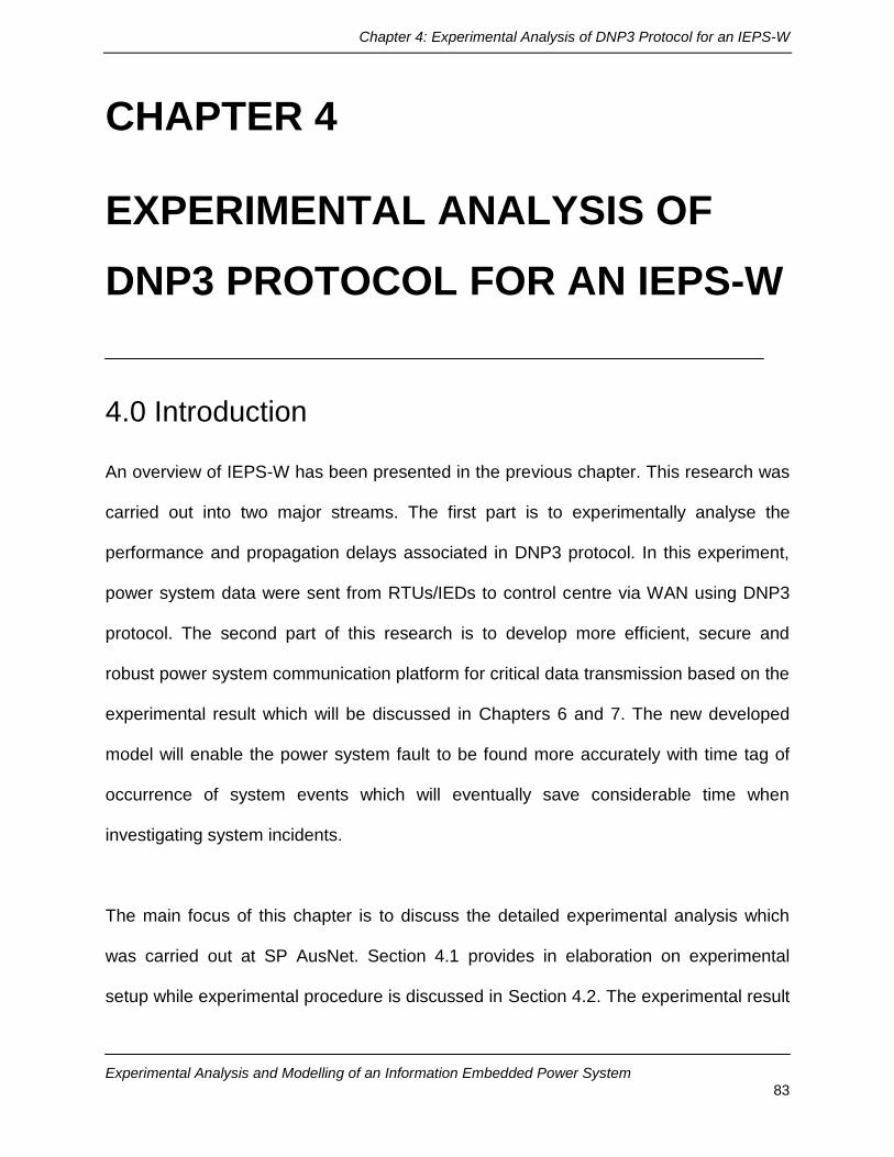
Chapter 4: Experimental Analysis of DNP3 Protocol for an IEPS-W
Experimental Analysis and Modelling of an Information Embedded Power System 83
CHAPTER 4
EXPERIMENTAL ANALYSIS OF
DNP3 PROTOCOL FOR AN IEPS-W
4.0 Introduction
An overview of IEPS-W has been presented in the previous chapter. This research was
carried out into two major streams. The first part is to experimentally analyse the
performance and propagation delays associated in DNP3 protocol. In this experiment,
power system data were sent from RTUs/IEDs to control centre via WAN using DNP3
protocol. The second part of this research is to develop more efficient, secure and
robust power system communication platform for critical data transmission based on the
experimental result which will be discussed in Chapters 6 and 7. The new developed
model will enable the power system fault to be found more accurately with time tag of
occurrence of system events which will eventually save considerable time when
investigating system incidents.
The main focus of this chapter is to discuss the detailed experimental analysis which
was carried out at SP AusNet. Section 4.1 provides in elaboration on experimental
setup while experimental procedure is discussed in Section 4.2. The experimental result

Chapter 4: Experimental Analysis of DNP3 Protocol for an IEPS-W
Experimental Analysis and Modelling of an Information Embedded Power System 84
has been presented in section 4.3. Finally, conclusion remarks have been provided in
Section 4.4.
4.1 Experimental setup
An experimental analysis is required for any available power system communication
protocols before deploying it into power grid to ensure the employed protocol suits the
particular power system infrastructure. A real life experimental platform was created at
SP AusNet in order to experimentally measure and characterise measurement delay
errors in a scaled down version of a real time information embedded power system
when power system data are being sent over WAN using DNP3 protocol as shown in
Figure 4.1. This setup allows for measuring delays in sending a typical set of power
system bus measurements from RTUs to an energy control center. The contemporary
digital RTU50 has been used to transmit data via WAN to the control centre.
The WAN in this experiment involves four routers, three switches and two firewalls that
make the communication backbone for data transmission. The SCADA switches are
CISCO 4003 and the SCADA routers are CISCO 3640. The corporate network to
SCADA firewall is a CISCOPIX 520. There are CISCO 7206 core routers, CISCO 3550-
24 switches, PIX 535 firewalls at Richmond Terminal Station (RTS), and CISCO 7206
outside routers to connect to the WAN links on the Richmond side. At the terminal
stations, there are CISCO 2620 routers and CISCO 3550-24 switches which were

Chapter 4: Experimental Analysis of DNP3 Protocol for an IEPS-W
Experimental Analysis and Modelling of an Information Embedded Power System 85
connected to the test RTUs. The communication link is a 2 Mega bytes link with 8
terminal stations connected in a ring communicating from the two outside routers.
Real time data are being sent from RTU to the control centre via WAN in different
stages of network utilisation. The RTU is located at Richmond Terminal Station and the
control centre was positioned at Victoria Network Switching Centre (VNSC). Other
features and characteristics involved in this experiment are summarised in Table 4.1.
The RTUs in this experiment have been configured to accommodate DNP3 and
communicate via WAN. Experimental set is depicted in Figure 4.1.
Table 4.1: Summary of experimental features and characteristics involved in
DNP3-WAN (TCP/IP) experiment
Protocol use DNP3 over WAN
Repeat count 10000
Datagram size 18024 bytes
Communication link type Fast Ethernet 10/100
Transport mode TCP/IP
Timing Clock TEKRON precision clock
Chapter 4: Experimental Analysis of DNP3 Protocol for an IEPS-W
Experimental Analysis and Modelling of an Information Embedded Power System 86
Figure 4.1: Experimental set-up

Chapter 4: Experimental Analysis of DNP3 Protocol for an IEPS-W
Experimental Analysis and Modelling of an Information Embedded Power System 87
ASE2000 communication test set developed by Applied System Engineering, Inc was
used to simulate the experiment and collect the data. The experiment has run several
times in different network utilisation. Data are sent in every 2-second from RTU to
control centre while power system uses DNP3 over WAN as its communication
backbone.
The ASE2000 is a computer based Communication Test Set that supports a large
number of RTU/IED protocols. The ASE2000 is the latest in the ASE Test Set series
and offers some significant improvements over earlier versions.
The ASE2000 has been completely re-engineered as a windows application and
incorporates many new features that have been requested as desirable additions over
earlier Test Set versions. Some of the more significant ones are:
The Line Monitor view is now divided into two panes with raw data on the left
and interpreted data on the right. Either pane can be viewed separately or
the two viewed side-by-side. This layout improves readability since raw and
interpreted data is no longer interspersed.
An Input Point view has been added that displays input point data (analog,
digital, pulse) in a tabular format. If just input point data values are of interest
and not other communication line message information, then this provides an
excellent view of the data. The view shows RTU ID, point ID, and point value,
time tags, as well as quality code information for applicable protocols (DNP

Chapter 4: Experimental Analysis of DNP3 Protocol for an IEPS-W
Experimental Analysis and Modelling of an Information Embedded Power System 88
3.0). Engineering units conversion coefficients, digital state names, high/low
alarms limits, and point and RTU names can be entered to provide a more
―operational‖ viewing presentation of the data.
The Analog Control and Digital Control views are shortcuts for configuring
control output request sequences. This provides the ability to sequence
control output commands (e.g., trip/close) and values to a set of output points.
For timing analysis and troubleshooting certain timing problems, the Line
Analyser view can be used to plot data and carrier signals on both lines (to
RTU, to Master) with millisecond resolution.
In addition to the new features described above, the ASE2000 supports the same basic
Test Set modes:
1. Monitor Mode - Monitor, in a passive mode, communication between
a master and slave device (data from both the Master to RTU and
RTU to Master are displayed).
2. Master Simulation Mode - Communicate directly to an RTU by issuing
data, control, and other requests
3. RTU Simulation Mode - Respond directly to the master by simulating
one or more RTUs on a single line; each response can additionally
simulate analog, digital and pulse accumulator point changes.

Chapter 4: Experimental Analysis of DNP3 Protocol for an IEPS-W
Experimental Analysis and Modelling of an Information Embedded Power System 89
4.2 Experimental procedures
DNP3 protocol was not default protocol in use at SP AusNet SCADA network at the
time when the experiment was conducted, hence, it was challenging to create a
platform to conduct the experiment with data feeding in real time from transmission
system to RTS where IEDs/RTUs are located. A new purpose built platform was created
to conduct the experiment in which real time data are fed to the control centre from
RTS. After setting up the equipments and communications facilities, there were major
difficulties in establishing initial communication between RTUs and other communication
devices at the control centre. After several weeks of dedicated efforts, communication
link was established between RTS and control centre using DNP3 protocol over WAN.
Once communication was established, different properties of ASE2000 communication
Test Set have been set to initiate the experiment. As depicted in Figure 4.2, one master
unit and 2 RTU slave units have been selected for this experiment.
Figure 4.2: Control room (master) and slaves (RTUs) setting

Chapter 4: Experimental Analysis of DNP3 Protocol for an IEPS-W
Experimental Analysis and Modelling of an Information Embedded Power System 90
However, one slave RTU was used during the experiment. Master Unit was located at
VNSC while RTUs were positioned at RTS. Figure 4.3 shows the time interval chosen
for the data to be sent. As seen in the figure, data were sent in every 2 seconds from
RTU to the control centre SCADA system.
Figure 4.3: Time interval setting
he performance analysis of DNP3-WAN was carried out with extreme precision since
the experiment investigates at millisecond accuracy. The experiment was set to record
data transmission rate in millisecond as depicted in Figure 4.4.
Figure 4.4: Time setting up to milliseconds

Chapter 4: Experimental Analysis of DNP3 Protocol for an IEPS-W
Experimental Analysis and Modelling of an Information Embedded Power System 91
DNP3 involves three different classes of data along with many other features which can
be incorporated. The details ‗Class features‘ is discussed in chapter 5. For this
experiment, Class 1, Class 2 and Class 3 data type to be transmitted have been set as
shown in Figure 4.5. Furthermore, the property is set to accommodate unsolicited data
in this experiment.
Figure 4.5: DNP3 Classes
As mentioned before, UDP is not suitable to adopt in DNP3-WAN. Hence, TCP/IP was
chosen as shown in Figure 4.6 as mode of transport since it guarantees data
transmission which is vital in power system. There were many other properties which
were required to be set up that have not been shown in this thesis. Figure 4.7 shows
ASE2000 communication Test Set activity timeline view for DNP3 -WAN after setting all
the required parameters and properties as mentioned above.

Chapter 4: Experimental Analysis of DNP3 Protocol for an IEPS-W
Experimental Analysis and Modelling of an Information Embedded Power System 92
Figure 4.6: ASE2000 communication Test Set: TCP as transport mode
Figure 4.7: Activity timeline for DNP3-LAN/WAN (TCP/IP)
The communication was successfully established and the experiment was successfully
run for several weeks to observe performance of DNP3 over WAN.

Chapter 4: Experimental Analysis of DNP3 Protocol for an IEPS-W
Experimental Analysis and Modelling of an Information Embedded Power System 93
The activity Timeline is displayed in the upper right-hand corner of the Test Set window.
This time-scaled view shows communication line activity and carrier signals. Data is
presented as a solid bar, while carrier signals is plotted as a line above and below the
data bars.
4.3 Experimental results
The experimental setup in Figure 4.1 was used to measure propagation delay
associated in IEPS-W when data are sent from RTUs to control room using DNP3 over
WAN. The experiment was carried out in different data traffic and carefully observed the
performance characteristic of data traffic. For each experimental run, a group of 10,000
measurement packets were sent from RTU to the control center. Experiments were run
using TCP transport protocols as UDP is not suitable in DNP3 over WAN as UDP does
not provide message guarantee services.
The RTU response time was set to record the delay in milliseconds as hh:mm: ss: ms
since the experiment was conducted to investigate into millisecond precision. Table 4.2
shows the representation of experimental data for 10% data traffic while 10000
measurement packets were sent from RTU to the control center using DNP3 over WAN.
The data sent and received shown in the table are in hour, minute, second and
millisecond format. The details experimental data can be found in Appendix A.

Chapter 4: Experimental Analysis of DNP3 Protocol for an IEPS-W
Experimental Analysis and Modelling of an Information Embedded Power System 94
Table 4.2: Propagation delay with 10% data traffic
Data sent from RTU
Data Received at Control Centre
Propagation delay (ms)
11:47:18.130 11:47:18.138 0:00:00.008
11:47:20.239 11:47:20.248 0:00:00.009
11:47:22.348 11:47:22.359 0:00:00.011
11:47:24.457 11:47:24.463 0:00:00.006
11:47:26.566 11:47:26.578 0:00:00.012
11:47:28.672 11:47:28.683 0:00:00.011
11:47:30.781 11:47:30.794 0:00:00.013
11:47:32.888 11:47:32.904 0:00:00.016
11:47:34.997 11:47:35.010 0:00:00.013
11:47:37.105 11:47:37.117 0:00:00.012
The experimental results involving propagation delays obtained in DNP3-WAN (TCP/IP)
is depicted in graphical form in Figure 4.8.
0:00:00.000
0:00:00.002
0:00:00.003
0:00:00.005
0:00:00.007
0:00:00.009
0:00:00.010
0:00:00.012
0:00:00.014
0:00:00.016
0:00:00.017
1 2 3 4 5 6 7 8 9 10
Time, s
Pro
pag
ati
on
Dela
y,
ms m
s
Figure 4.8: Propagation delay with 10% data traffic in DNP3-WAN (TCP/IP)

Chapter 4: Experimental Analysis of DNP3 Protocol for an IEPS-W
Experimental Analysis and Modelling of an Information Embedded Power System 95
It can be observed that propagation delay involve in this instance is between 6 -16 ms.
The result obtained are based on less traffic in the network. However, as data traffic to
be transmitted from RTU to control room is increased, the propagation delay appears to
be significantly highly. Table 4.3 presents data with 20% increase in traffic from the
initial case.
Table 4.3: Propagation delay with 20% increased data traffic
Data sent from RTU
Data Received at Control Centre Propagation delay (ms)
15:21:47.454 15:21:47.478 0:00:00.024
15:21:49.564 15:21:49.585 0:00:00.021
15:21:51.673 15:21:51.696 0:00:00.023
15:21:53.783 15:21:53.804 0:00:00.021
15:21:55.893 15:21:55.913 0:00:00.020
15:21:58.001 15:21:58.019 0:00:00.018
15:22:00.110 15:22:00.134 0:00:00.024
15:22:02.220 15:22:02.236 0:00:00.016
15:22:04.330 15:22:04.339 0:00:00.009
15:22:06.440 15:22:06.461 0:00:00.021
As expected, propagation delay has increased when network traffic is increased to 20%
as shown in Figure 4.9. The minimum delay in this case is 9 ms while the maximum
propagation delay rises 24 ms.

Chapter 4: Experimental Analysis of DNP3 Protocol for an IEPS-W
Experimental Analysis and Modelling of an Information Embedded Power System 96
0:00:00.000
0:00:00.004
0:00:00.009
0:00:00.013
0:00:00.017
0:00:00.022
0:00:00.026
1 2 3 4 5 6 7 8 9 10
Time, s
Pro
pag
ati
on
Dela
y,
ms m
s
Figure 4.9: Propagation delay in DNP3-WAN (TCP/IP) with 20% traffic increase
As data is increased in the network, the propagation delay also increases substantially.
Table 4.4 gives performance result when network traffic is increased to 40%.
Table 4.4: Propagation delay with 40% increased data traffic
Data sent from RTU
Data Received at Control Centre
Propagation delay (ms)
11:36:02.357 11:36:02.379 0:00:00.022
11:36:04.624 11:36:04.647 0:00:00.023
11:36:06.890 11:36:06.914 0:00:00.024
11:36:09.156 11:36:09.182 0:00:00.026
11:36:11.423 11:36:11.444 0:00:00.021
11:36:13.689 11:36:13.707 0:00:00.018
11:36:15.955 11:36:15.976 0:00:00.021
11:36:18.222 11:36:18.238 0:00:00.016
11:36:20.488 11:36:20.507 0:00:00.019
11:36:22.755 11:36:22.774 0:00:00.019

Chapter 4: Experimental Analysis of DNP3 Protocol for an IEPS-W
Experimental Analysis and Modelling of an Information Embedded Power System 97
With 40% network traffic, propagation delay grows with minimum delay of 16 ms and
while maximum delay is up to 26 ms as shown in Figure 4.10.
When network is loaded with 60 % traffic, the transmission delay has increased to 28
ms as depicted in Table 4.5 which has also been presented in Figure 4.11 as graphical
representation.
0:00:00.000
0:00:00.004
0:00:00.009
0:00:00.013
0:00:00.017
0:00:00.022
0:00:00.026
0:00:00.030
1 2 3 4 5 6 7 8 9 10
Time, s
Pro
pag
ati
ati
on
Dela
y,
ms,
ms
Figure 4.10: Propagation delay in DNP3-WAN (TCP/IP) with 40 % traffic increase
Table 4.5: Propagation delay with 60 % increased data traffic
Data sent from RTU
Data Received at Control Centre
Propagation delay (ms)
13:00:46.080 13:00:46.106 0:00:00.026
13:00:48.347 13:00:48.366 0:00:00.019
13:00:50.613 13:00:50.641 0:00:00.028
13:00:52.880 13:00:52.901 0:00:00.021
13:00:55.146 13:00:55.170 0:00:00.024

Chapter 4: Experimental Analysis of DNP3 Protocol for an IEPS-W
Experimental Analysis and Modelling of an Information Embedded Power System 98
13:00:57.412 13:00:57.435 0:00:00.023
13:00:59.679 13:00:59.706 0:00:00.027
13:01:01.945 13:01:01.972 0:00:00.027
13:01:04.212 13:01:04.219 0:00:00.007
13:01:06.478 13:01:06.498 0:00:00.020
0:00:00.000
0:00:00.004
0:00:00.009
0:00:00.013
0:00:00.017
0:00:00.022
0:00:00.026
0:00:00.030
1 2 3 4 5 6 7 8 9 10
Time, s
Pro
pag
ati
on
Dela
y,
ms m
s
Figure 4.11: Propagation delay in DNP3-WAN (TCP/IP) with 60 % traffic increase
As the network traffic increases with high amount of data passing through the network,
the propagation delay significantly increases. Table 4.6 and Figure 4.12 depict the
network performance when data are sent with 80% increase in traffic. The minimum
delay in this case is 18 ms with a maximum delay of 38 ms.

Chapter 4: Experimental Analysis of DNP3 Protocol for an IEPS-W
Experimental Analysis and Modelling of an Information Embedded Power System 99
Table 4.6: Propagation delay with 80 % increased data traffic
Data sent from RTU
Data Received at Control Centre
Propagation delay (ms)
9:41:42.084 9:41:42.111 0:00:00.027
9:41:44.351 9:41:44.374 0:00:00.023
9:41:46.617 9:41:46.638 0:00:00.021
9:41:48.883 9:41:48.921 0:00:00.038
9:41:51.150 9:41:51.180 0:00:00.030
9:41:53.416 9:41:53.438 0:00:00.022
9:41:55.683 9:41:55.703 0:00:00.020
9:41:57.949 9:41:57.970 0:00:00.021
9:42:00.215 9:42:00.234 0:00:00.019
9:42:02.482 9:42:02.500 0:00:00.018
Figure 4.12: Propagation delay in DNP3-WAN (TCP/IP) with 80 % traffic increase
0:00:00.000
0:00:00.004
0:00:00.009
0:00:00.013
0:00:00.017
0:00:00.022
0:00:00.026
0:00:00.030
0:00:00.035
0:00:00.039
0:00:00.043
1 2 3 4 5 6 7 8 9 10
Time, s
Pro
pag
ati
on
Dela
y,
msm
s

Chapter 4: Experimental Analysis of DNP3 Protocol for an IEPS-W
Experimental Analysis and Modelling of an Information Embedded Power System 100
Table 4.7 and Figure 4.13 summarises the performance results of DNP3-WAN (TCP/IP)
for an IEPS-W in the form of mean delay. As the data in this experiment suggests
propagation delay increases with the increased of network traffic. The mean delay with
10% of network traffic is 11.1 ms while mean delay increases to 23.9 ms when
experiment was 80 % data traffic. However, as can be seen in Appendix A, there are
occasions when traffic delay increases up to 100 ms or more.
Table 4.7: Summary of Experimental results in different network traffic
Mean Propagation delay in various network Traffic
(DNP3-WAN_TCP/IP)
0
5
10
15
20
25
30
10 20 40 60 80
%Network Traffic
Mean
Dela
y,
ms m
s
Figure 4.13: Mean propagation delay for DNP3-WAN (TCP/IP)
Network Traffic (%)
Mean propagation delay (ms)
10 11.1
20 19.7
40 20.9
60 22.9
80 23.9

Chapter 4: Experimental Analysis of DNP3 Protocol for an IEPS-W
Experimental Analysis and Modelling of an Information Embedded Power System 101
As stated earlier, there are hundreds of RTUs/IEDs which transmit data consistently to
the control room in real time using various power system communication protocols. The
data sent in this experimental analysis is only from one RTU. In practical, data will come
simultaneously from different IEDs. In such cases, propagation delay could be
significantly high failing to transmit critical data on time. This can cause catastrophic
failure for power system. Hence, communication protocols must be carefully designed
when it is intended to use in the broader communication network.
4.4 Conclusion An experimental investigation is vital to conduct before employing any protocols to
power grid as data are very critical to ensure high reliability of power system. DNP3 was
not originally developed to use in WAN environment, hence the experimental
investigation carried out in this project has contributed significantly. Details experimental
procedures along with experimental setup and experimental result have been presented
in this Chapter. Based on the results obtained from the experiment, it is apparent that a
more robust communication protocol is required to be used in a wider power system
network. The next chapter presents the development of DNP3 protocol in OPNET
modeller to further simulate it in order to develop a more effective and reliably
communication protocol to be used in IEPS-W.

Chapter 5: Modelling of DNP3 Protocol for an IEPS-W
Experimental Analysis and Modelling of an Information Embedded Power System 102
CHAPTER 5 MODELLING OF DNP3 PROTOCOL
FOR AN IEPS-W
5.0 Introduction
A detailed discussion on experimental analysis of the DNP3 over WAN for IEPS-W was
presented in Chapter 4 where a significant propagation delay was found while power
system data were sent from RTUs to control centre via WAN using DNP3 protocol.
This chapter presents the development and modelling of DNP3 protocol in an OPNET
environment. OPNET has been used to develop DNP3 protocol and further analyse it in
order to model a better information embedded power system to be used in WAN.
Section 5.1 starts with a brief introduction on OPNET modeller which was chosen to
develop DNP3 protocol in order to build a more reliable and secure power system
communication protocol. OPNET is an Object Oriented (OO) discrete-event network
simulator allowing for the modelling, implementation, simulation and performance
analysis of communication networks and distributed applications. Section 5.2 then
presents the development of data link and transport layer of DNP3 protocol in OPNET
environment. A detailed description on the development of application layer of DNP3 is
given in Section 5.3. Conclusion is made in Section 5. 4.

Chapter 5: Modelling of DNP3 Protocol for an IEPS-W
Experimental Analysis and Modelling of an Information Embedded Power System 103
5.1 Brief overview of OPNET modeller
OPNET Modeller [115] is the industry‘s leading simulator specialised for network
research and development. It allows to design and study communication networks,
devices, protocols and applications with greater flexibility. It provides a graphical editor
interface to build models for various network entities from physical layer modulator to
application processes. All the components are modelled in an object-oriented approach
which gives intuitive easy mapping to the real systems. It gives a flexible platform to test
new ideas and solutions with low cost. OPNET is a simulator built on top of a discrete
event system. It simulates the system behaviour by modelling each event happening in
the system and processes it by user-defined processes. It uses a hierarchical strategy
to organise all the models to build a whole network. OPNET also provides programming
tools to define any type of packet format to be used in purpose-built protocols.
Programming in OPNET includes the following major tasks:
Define protocol packet format,
Define the state transition machine for processes running the protocol,
Define process modules and transceiver modules needed in each device
node.
It allows to finally define the network model by connecting the device nodes together
using user-defined link models.

Chapter 5: Modelling of DNP3 Protocol for an IEPS-W
Experimental Analysis and Modelling of an Information Embedded Power System 104
5.2 Development and modelling of DNP3 protocol
using OPNET modeller
As stated earlier, OPNET platform has been used to develop and model each layer of
DNP3 protocol. As discussed in Chapter 3, DNP3 protocol provides the rule for
substation IEDs and SCADA devices to communicate data and control commands. It
was designed to optimise the transmission of data acquisition information and control
commands from one control centre to other IEDs. The internet protocol suite and DNP3
[105] use the OSI layering paradigm. Each part of the protocol stack in one station
logically communicates with the corresponding part in the other station(s). Therefore,
DNP3 is built on top of the internet protocol suite since the internet layers appear
transparent to the DNP layers as shown in Figure 5.1.
Figure 5.1: DNP3 protocol [105]

Chapter 5: Modelling of DNP3 Protocol for an IEPS-W
Experimental Analysis and Modelling of an Information Embedded Power System 105
As discussed earlier, one of the major components of IEPS-W is control centre or master
station in power system. Control centre communicates with outstation field devices such as
IEDs or RTUs to monitor and protect modern power system via WAN platform incorporating
various power systems communication protocols. A master station representing control
centre and an IED have been developed based on DNP3 for an information embedded
power system as shown in Figure 5.2 using OPNET Modeler. There are numerous code
involved behind this blocks while developing DNP3 protocol.
Figure 5.2: Control centre and IED in OPNET platform

Chapter 5: Modelling of DNP3 Protocol for an IEPS-W
Experimental Analysis and Modelling of an Information Embedded Power System 106
As described in Figure 5.1, DNP3 protocol has three layers which are DNP link layer, DNP
transport layer and DNP application layer. DNP3 sits on top of TCP/IP protocol suite making
it easier to migrate it to Internet Technology. Figure 5.3 shows OPNET representation of
Figure 5.1 whereby DNP3 layer sits on top of TCP/IP protocol suite. The detailed discussion
on the development of master station (control centre) has been discussed in the following
sections. DNP3 protocol has been developed to be used in both Master station and IED
using OPNET modeller as shown in Figure 5.3.
Figure 5.3: DNP3 protocol stack in OPNET environment

Chapter 5: Modelling of DNP3 Protocol for an IEPS-W
Experimental Analysis and Modelling of an Information Embedded Power System 107
5.2.1 Implementation of DNP3 data link layer
The main purpose of the DNP3 data link layer [116] is twofold. It provides transfer of
information or Link Service Data Unit (LSDU) across the physical link along with
indications of other events such as link status. DNP3 handles both connectionless and
connection oriented services. The communication requirements of the network layer
and the pseudo-transport layer are satisfied by the data link layer service primitives.
The following data link functions have been executed in developing DNP3 data link layer:
Performing message retries
Synchronising and handling of the frame control bit in the control word
Setting and clearing the data flow control bit based on buffer availability
Automatically establishing a connection based on the destination parameter in a
dial-up environment when a directed service is requested by the user
Disconnection in a dial-up environment
Packing user data into the defined frame format and transmitting the data to the
physical layer
Unpacking the frames that are received from the physical layer into user data
Controlling all aspects of the physical layer
Performing collision avoidance/detection procedures to ensure the reliable transfer
of data across the physical link
Responding to all valid frames (function codes) received from the physical layer.

Chapter 5: Modelling of DNP3 Protocol for an IEPS-W
Experimental Analysis and Modelling of an Information Embedded Power System 108
The data link is responsible for providing the following services:
Exchange of Service Data Units (SDUs) between peer DNP data links
Error notification to data link user
Sequencing of SDUs
Prioritised SDU delivery
Quality SDU delivery.
Priority delivery is set to EXPEDITED or NORMAL to indicate a high or low priority request.
Quality delivery is categorised as SEND-NO-REPLY or SEND-CONFIRM to indicate
whether or not message acknowledgment is required.
The data link service primitives are illustrated in pseudo code to illustrate the requirements
and behaviour in a real implementation and are not intended as an exact interface
definition.
Data link request (REQ) services is used after the data link has been initialized and
configured by the system as follows.
confirm = request_data_link_service ( SERVICE, TIME_SERVICE, destination, source, send_data_buffer, send_count, retry_flag, time_of_transmission )

Chapter 5: Modelling of DNP3 Protocol for an IEPS-W
Experimental Analysis and Modelling of an Information Embedded Power System 109
SERVICE Service to perform TIME_SERVICE Guaranteed time service to perform destination Destination address to use in sent
message source Source address to use in sent message send_data_buffer Data to send in message send_count Number of octets in message retry_flag Instructs data link layer to retry
unacknowledged frames or not time_of_transmission Time that first bit of first octet of message
is to be sent time_of_transmission Time that first bit of first octet of message
was sent
Data link indications (IND) is set to request by the service user as follows.
indications = request_data_link_indications ( source_address, destination_address, received_data_buffer, received_data_count, time_of_reception)
source_address Source address of received message
destination_address Destination address of received address
received_data_buffer Received message
received_data_count Number of octets in message
time_of_reception Time at which first bit of first octet of message was received

Chapter 5: Modelling of DNP3 Protocol for an IEPS-W
Experimental Analysis and Modelling of an Information Embedded Power System 110
In this layer, a primary station sends a SEND-CONFIRM RESET frame to a secondary
station. The secondary station receives the message and respond with an ACK confirm
frame. Figure 5.4 shows the implementation of the above rules and functions which was
developed using OPNET environment.
Figure 5.4: DNP3 data link layer in OPNET environment
5.2.2 Implementation of DNP3 transport layer
Master stations, submaster stations and outstations or IEDs use transport functions
[117] to pass messages between primary (originating-control centre) stations and
secondary (receiving-IEDs) stations. In this protocol, master stations, submaster
stations and outstations are both originators (primary stations) and receivers (secondary
stations).

Chapter 5: Modelling of DNP3 Protocol for an IEPS-W
Experimental Analysis and Modelling of an Information Embedded Power System 111
The communication requirements of the network layer and the application layer are
satisfied by the pseudo-transport layer service primitives.
The following functions have been implemented in pseudo-transport layer of DNP3
protocol:
Pack user data into multiple frames (more than one) of the defined DNP3
Data Link frame format and use the services of the DNP3 Data Link for
transmitting the data
Unpack multiple frames that are received from the data link into user data
Control all aspects of the data link excluding data link configuration.
The pseudo-transport layer is designed to provide the following services:
Exchange of SDUs between peer DNP3 pseudo-transport layers
Error notification to transport user
Sequencing of SDUs
Prioritised SDU delivery
Quality control of SDU delivery.
The pseudo-transport layer function is specific only for those messages that are larger
than one Link Protocol Data Unit (LPDU) between primary and secondary stations. This
pseudo-transport layer acts as the DNP data link user in a protocol stack consisting of
only the DNP Data Link and DNP Application Layer. This functionality allows the

Chapter 5: Modelling of DNP3 Protocol for an IEPS-W
Experimental Analysis and Modelling of an Information Embedded Power System 112
pseudo-transport layer to disassemble one Transport Service Data Unit (TSDU) into
multiple (more than one) Transport Protocol Data Units (TPDUs), or frames and
assemble multiple (more than one) TPDUs into one TSDU. The pseudo-transport layer
takes one TSDU (user data) and breaks it into several sequenced TPDUs (each with
Transport Protocol Control Information (TPCI)). Each TPDU is sent to the data link layer
as Link Service Data Unit (LSDU) for transmission. It also works in the reverse fashion.
The pseudo-transport layer receives multiple TPDUs from the data link layer and
assembles them into one TSDU.
When a primary station transmits a message to a secondary station, the transport
functions break the message into LSDUs. These functions add a Transport layer
Header (TH) octet at the beginning of the user data fragments that contain the
information for the secondary station to reconstruct the complete message. The
secondary station checks the TH octet on reception of each LSDU for the correct
sequence and builds a TSDU message for higher layers. The TH contains information
that can identify the first frame, last frame and give every frame a six-bit sequence
number. This information is required to reconstruct a message and also to guard
against higher layers from receiving misdirected or incomplete messages.
5.2.2.1 Transport header
After the data link receives a complete frame, the data is presented to the transport.
The TH field is stripped out before the frame is combined with other frames belonging to
the same message. Figure 5.5 shows the structure of transport layer message layout.

Chapter 5: Modelling of DNP3 Protocol for an IEPS-W
Experimental Analysis and Modelling of an Information Embedded Power System 113
Figure 5.5: Transport layer message layout
When an application requests the transmission of a long message, the message is
broken into fragments small enough to fit in a single DNP3 Data Link frame. The
maximum size of a fragment is 249 octets of user data. The TH is added to the head of
the fragment and the maximum number of octets to be framed becomes 250 octets.
Figure 5.6 defines TH bits in details.
Figure 5.6: TH bit definitions
Where
FIN The final bit indicates that this frame of user data is the last frame of a
sequence which compromises a complete user message.
FIN = 0 More frames to follow
1 Final frame of a sequence
TH Transport control octet. One octet in length
USER DATA 1 to 249 octets
in length
-----------------------------------------------
| | | | | | | | |
| FIN | FIR | | | SEQUENCE | | |
| | | | | | | | |
-----------------------------------------------
BIT 7 6 5 4 3 2 1 0
-----------------
| | |
| TH | USER DATA |
| | |
-----------------

Chapter 5: Modelling of DNP3 Protocol for an IEPS-W
Experimental Analysis and Modelling of an Information Embedded Power System 114
FIR The first bit indicates that the frame is the first in a sequence of frame(s)
which comprise a complete message. When a secondary station receives
a frame with the FIR bit set, all previously received unterminated frame
sequences are discarded. If a complete user message is only one frame in
length, both the FIR and FIN bits are set.
FIR = 1 First frame of a sequence.
0 Not the first frame of a sequence.
SEQUENCE The sequence number of the frame is used to check that each frame is
being received in sequence. It guards against missing or duplicated
frames. All user messages start off with a sequence specified in the first
frame which has the FIR bit set.
The sequence number increments for each frame sent to or received from the same
address belonging to the same message and resets at the beginning of a new
message. The sequence number does not have to increment across message
boundaries, i.e. any sequence number is valid when the FIR bit is set.
5.2.2.2 Transmission of messages
Figure 5.7 illustrates the transmission of a single-frame message using the SEND -
CONFIRM frame service.

Chapter 5: Modelling of DNP3 Protocol for an IEPS-W
Experimental Analysis and Modelling of an Information Embedded Power System 115
Figure 5.7: Transmission of a single frame message
Figure 5.8 shows DNP3 transport layer in OPNET environment which incorporates all
functions and mechanism discussed earlier.
Figure 5.8: DNP3 transport lawyer in OPNET platform
FRAMES SENT FROM DATA LINK COMPLETE MESSAGE FROM APPLICATION
CONFIRM FRAMES RECEIVED
---------------
| DESTINATION | parameter from application
---------------
---------------
| USER DATA |
| |
| 30 octets |
---------------
--------------
| DESTINATION | parameter to data link
--------------
--------------
| FIR = 1 |
| FIN = 1 | 1 TH octet
| SEQUENCE = 1 |
| USER DATA 0 | send 30 user octets plus 1 TH = 31 octets
SEND <----- --------------
CONFIRM -------> --------------------> SUCCESS to application layer

Chapter 5: Modelling of DNP3 Protocol for an IEPS-W
Experimental Analysis and Modelling of an Information Embedded Power System 116
5.3 Development and Implementation of DNP3
application layer
DNP3 Application Layer [118] is the top and main layer which provides standardised
functions, data formats and procedures for the efficient transmission of data acquisition
values, attributes and control commands as shown in Figure 5.9. DNP3 user‘s software
is the application program that makes a device unique, whether it is a master, Intelligent
Electronic Device (IED) or a data concentrator. It makes use of the Application Layer‘s
services to send messages to, and receive messages from another DNP3 device. In
this specification, the master station is defined as the station sending a request
message and the outstation is the slave device, RTU or IED to which the requested
messages is destined. In DNP3, only designated master stations can send Application
Layer request messages and only outstations can send Application Layer Response
messages. Figure 5.10 shows the sequence of Application Layer messages between
one master and one outstation (IED).
Figure 5.9: DNP3 device interface
Physical Media
Master Outstation
DNP3Application Layer
DNP3Application Layer
Transport Function
DNP3Data Link Layer
Transport Function
DNP3Data Link Layer
User Layer User Layer

Chapter 5: Modelling of DNP3 Protocol for an IEPS-W
Experimental Analysis and Modelling of an Information Embedded Power System 117
Figure 5.10: Message sequence
As shown in Figure 5.10, the master station sends an Application Layer Request to the
outstation which returns an Application Layer Response. The outstation can decide to
spontaneously transmit data using an Application Layer Unsolicited Response
message. For a master, a request/response transaction with a particular outstation must
be completed before another request can be sent to that outstation. A master station
may accept unsolicited responses while the request transaction is in progress.
For an outstation, a request/response transaction must be completed before any other
requests are accepted or unsolicited responses are sent. Unsolicited responses can be
sent before or after the request/response transaction but not during transaction of
message.
In addition, each response or request can consist of 1 or more individual fragments.
Each fragment however should be digestible (parsable) and therefore executable
Master Outstation
Send Request --------------------> Accept request and process
<-------------------- Optional confirmation
Accept response <----------------- Send Response
Optional confirmation --------------------------------->
Important change detected
Accept response <----------------- Send Unsolicited Response
Optional confirmation --------------------------------->

Chapter 5: Modelling of DNP3 Protocol for an IEPS-W
Experimental Analysis and Modelling of an Information Embedded Power System 118
(because the function code is part of every fragment). It is advised that devices with
limited message storage capabilities should only be sent single fragment message
requests when the expected response (from all fragments sent) is larger than one
fragment. This is to ensure that devices can process a request and build, and more
importantly send a response before the next request is received. Otherwise, multi-
fragment messages may require multi-fragment responses which may require more
message storage than the device has available.
5.3.1. Message structure
Masters formulate and send request messages for an outstation IED to return data,
carry out a command or perform a special activity. Upon receipt, an outstation performs
or initiates the requested action, generates an appropriate response message and
transmits it back to the master with the data, results or special information.
An application request header is used in requests from masters and has two fields as
shown in Figure 5.11. Each field is one octet in length.
Application Request Header
Application Control
(1 octet) Function Code
(1 octet)
Figure 5.11: Application request header

Chapter 5: Modelling of DNP3 Protocol for an IEPS-W
Experimental Analysis and Modelling of an Information Embedded Power System 119
An application response header is used in responses from outstations IED and has
three fields as depicted in Figure 5.12. The application control and function code fields
are the same as in an application request header.
Application Response Header
Application Control (1 octet)
Function Code (1 octet)
Internal Indications (2 octets)
Figure 5.12: Application response header
The application control octet provides information needed to construct and reassemble
multiple fragment messages and to indicate whether the receiver‘s Application Layer
must return an Application Layer confirmation message. It also provides information to
assist in duplicate message detection. Application control fields is shown in Figure 5.13.
Bit # 7 6 5 4 3 2 1 0
Fields FIR FIN CON UNS SEQ
Figure 5.13 Application control fields
The FIR field is a single bit, which when set, indicates that this is the first fragment of a
message. The FIN field is a single bit, which when set, indicates that this is the final
fragment of a message. The CON field is a single bit, which when set, indicates that the
receiver‘s Application Layer must return an application confirmation message. An
Application Layer confirmation message is a very brief message that is used to verify

Chapter 5: Modelling of DNP3 Protocol for an IEPS-W
Experimental Analysis and Modelling of an Information Embedded Power System 120
that a complete fragment arrived at its destination. The UNS field is a single bit, which
when set, indicates the message contains an unsolicited response or a confirmation of
an unsolicited response. The SEQ field is 4 bits wide. It is used to verify that fragments
are received in the correct order and to detect duplicated fragments.
The function code octet identifies the purpose of the message. Request messages from
masters use function codes in the range of 1 to 128, and response messages from
outstations use function codes with values ranging from 129 to 255 as shown in Table
5.1. Application Layer confirmations use the CONFIRM function code.
The function code octet as mention in Figure 5.12 identifies the purpose of the
message. Request messages from masters use function codes in the range of 1 to 128,
and response messages from outstations use function codes with values ranging from
129 to 255 as shown in Table 5.1. Application Layer confirmations use the CONFIRM
function code. Table 5.1 gives a brief description of each function code.
Table 5.1: Function Code Table
Message Type
Code NAME Brief Description
Confir-mation
0 0x00
CONFIRM
Confirm Function Code: Master sends this to an outstation to confirm the receipt of an Application Layer fragment.
Request 1 0x01
READ Read Function Code: Outstation shall return the data specified by the objects in the request.

Chapter 5: Modelling of DNP3 Protocol for an IEPS-W
Experimental Analysis and Modelling of an Information Embedded Power System 121
Message Type
Code NAME Brief Description
Request 2 0x02
WRITE
Write Function Code: Outstation shall store the data specified by the objects in the request.
Request 3 0x03
SELECT
Select Function Code: Outstation shall select (or arm) the output points specified by the objects in the request in preparation for a subsequent operate command. The outstation shall not activate the outputs until a request with a matching Operate function code is received.
Request 4 0x04
OPERATE
Operate Function Code: Outstation shall activate the output points selected (or armed) by a previous select function code command.
Request 5 0x05
DIRECT_OPERATE
Direct Operate Function Code: Outstation shall immediately actuate the output points specified by the objects in the request. A prior matching select command is not required.
Request 6 0x06
DIRECT_OPERATE_NR
Direct Operate – No Response Function Code: Same as function code 5 but outstation shall not send a response.
Request 7 0x07
IMMED_FREEZE
Immediate Freeze Function Code: Outstation shall copy the point data values specified by the objects in the request to a separate freeze (or holding) buffer (or register).
Request 8 0x08
IMMED_FREEZE_NR
Immediate Freeze – No Response Function Code: Same as function code 7 but outstation shall not send a response.
Request 9 0x09
FREEZE_CLEAR
Freeze and Clear Function Code: Outstation shall copy the point data values specified by the objects in the request into a separate freeze (or holding) buffer (or register). After the copy operation, clear the point data values to zero.

Chapter 5: Modelling of DNP3 Protocol for an IEPS-W
Experimental Analysis and Modelling of an Information Embedded Power System 122
Message Type
Code NAME Brief Description
Request 10 0x0A
FREEZE_CLEAR_NR
Freeze and Clear – No Response Function Code: Same as function code 9 but outstation shall not send a response.
Request 11 0x0B
FREEZE_AT_TIME
Freeze at Time Function Code: Outstation shall copy the point data values specified by the objects in the request to a separate freeze (or holding) buffer (or register) at the time and/or time intervals specified in a special time data information object.
Request 12 0x0C
FREEZE_AT_TIME_NR
Freeze at Time – No Response Function Code: Same as function code 11 but outstation shall not send a response.
Request 13 0x0D
COLD_RESTART
Cold Restart Function Code: Outstation shall perform a complete reset of all hardware and software in the device.
Request 14 0x0E
WARM_RESTART
Warm Restart Function Code: Outstation shall reset only portions of the device.
Request 15 0x0F
INITIALIZE_DATA
Initialize Data Function Code: Obsolete – do not use for new designs.
Request 16 0x10
INITIALIZE_APPL
Initialize Application Function Code: Outstation shall place the applications specified by the objects in the request into the ready to run state.
Request 17 0x11
START_APPL
Start Application Function Code: Outstation shall start running the applications specified by the objects in the request.
Request 18 0x12
STOP_APPL
Stop Application Function Code: Outstation shall stop running the applications specified by the objects in the request.

Chapter 5: Modelling of DNP3 Protocol for an IEPS-W
Experimental Analysis and Modelling of an Information Embedded Power System 123
Message Type
Code NAME Brief Description
Request 19 0x13
SAVE_CONFIG
Save Configuration Function Code: Outstation shall store into non-volatile memory the contents of a configuration file located in volatile memory.
Request 20 0x14
ENABLE_UNSOLICITED
Enable Unsolicited Responses Function Code: Enables outstation to initiate unsolicited responses from points specified by the objects in the request.
Request 21 0x15
DISABLE_UNSOLICITED
Disable Unsolicited Responses Function Code: Prevents outstation from initiating unsolicited responses from points specified by the objects in the request.
Request 22 0x16
ASSIGN_CLASS
Assign Class Function Code: Outstation shall assign the events generated by the points specified by the objects in the request to one of the classes.
Request 23 0x17
DELAY_MEASURE
Delay Measurement Function Code: Outstation shall report the time it takes to process and initiate the transmission of its response. This allows the master to compute the propagation delay in the communications channel. Used for non-LAN time synchronization.
Request 24 0x18
RECORD_CURRENT_TIME
Record Current Time Function Code: Outstation shall save the time when the last octet of this message is received. Used for LAN time synchronization.
Request 25 0x19
OPEN_FILE
Open File Function Code: Outstation shall open a file.
Request 26 0x1A
CLOSE_FILE
Close File Function Code: Outstation shall close a file.
Request 27 0x1B
DELETE_FILE
Delete File Function Code: Outstation shall delete a file.

Chapter 5: Modelling of DNP3 Protocol for an IEPS-W
Experimental Analysis and Modelling of an Information Embedded Power System 124
Message Type
Code NAME Brief Description
Request 28 0x1C
GET_FILE_INFO
Get File Information Function Code: Outstation shall retrieve information about a file.
Request 29 0x1D
AUTHENTICATE_FILE Authenticate File Function Code: Outstation shall return a file authentication key.
Request 30 0x1E
ABORT_FILE Abort File Function Code: Outstation shall abort a file transfer operation.
Request 31 0x1F
ACTIVATE_CONFIG
Activate Configuration Function Code: Outstation shall use the configuration specified by the objects in the request.
32 0x20 to 128 0x80
Reserved.
Response 129 0x81
RESPONSE
Solicited Response Function Code: Master shall interpret this fragment as an Application Layer response to an Application Layer request sent by the master.
Response 130 0x82
UNSOLICITED_RESPONSE
Unsolicited Response Function Code: Master shall interpret this fragment as an unsolicited response that was not prompted by an explicit request.
Response
131 0x83 to 255 0xFF
Reserved.
The detailed function code description is presented in Appendix B. The internal
indication field appears in application response headers immediately following the
function code octet. This field has two octets. The bits in these two octets indicate
certain states and error conditions within the outstation.

Chapter 5: Modelling of DNP3 Protocol for an IEPS-W
Experimental Analysis and Modelling of an Information Embedded Power System 125
5.3.2 Fragment rules
The following rules have been adopted while developing DNP3 application layer:
Rule 1 DNP3 devices that are able to set their maximum transmit fragment size
larger than 2048 octets provide configuration down to 2048 octets.
Rule 2 All devices must accept fragments as small as 2 octets.
Rule 3 Outstations prepare to receive fragment sizes of at least 249 octets, and
masters must be prepared to receive fragment sizes of at least 2048 octets.
Rule 4 Master devices only send requests that fit within a single fragment.
Rule 5 Master devices accept multiple fragment responses.
Rule 6 An outstation device returns all of its event and static data together, within a
single response. If necessary, it shall use multiple fragments to convey the
entire response.
Rule 7 Each fragment must be individually and completely passable. The FIR bit is
set in the fragment that begins a message.
Rule 8 The FIN bit is set in the fragment that ends a message.
Rule 9 A message may consist of a single fragment having both the FIR and FIN bits
set.
Rule 10 Masters shall never request Application Layer confirmation; i.e. they must not
set the CON bit in request messages. This practice is now obsolete.

Chapter 5: Modelling of DNP3 Protocol for an IEPS-W
Experimental Analysis and Modelling of an Information Embedded Power System 126
Rule 11 Outstations that receive a properly formatted fragment with the CON bit set,
must immediately respond with an Application Layer confirm message (For
backward compatibility).
Rule 12 Masters that receive a properly formatted fragment with the CON bit set,
respond with an Application Layer confirm message before sending any other
request message to that outstation.
Rule 13 For each new, non-retry request fragment it sends, a master increments the
SEQ number by one count from its previous request fragment.
Rule 14 The first fragment of a solicited (polled) response message have the same
SEQ number as the SEQ number in the request fragment. If the response
requires multiple fragments, each subsequent fragment shall use a SEQ
number incremented by one count from the previous.
Rule 15 A master send a retry request message if it uses the same SEQ number and
all the other octets in the retry message match the original request message.
Rule 16 An outstation shall not retry sending solicited response messages.
Rule 17 A fragment containing a CONFIRM function code use the same SEQ number
and UNS bit state as are in the fragment being confirmed.
Rule 18 Outstations ignore the SEQ number in broadcast request messages.
Rule 19 The SEQ numbers sent by an outstation in unsolicited responses are distinct
from, and have no relationship to the SEQ numbers it sends in solicited
responses.

Chapter 5: Modelling of DNP3 Protocol for an IEPS-W
Experimental Analysis and Modelling of an Information Embedded Power System 127
Rule 20 An outstation that sends unsolicited responses choose any SEQ number for
its first message after a restart. The master must accept these messages.
Rule 21 An outstation that restarts ignore the SEQ number in the first request it
receives from a master after the restart, but otherwise shall execute the
request. Thereafter, the outstation should examine the SEQ numbers in the
received requests.
Rule 22 An outstation requests an Application Layer confirmation when it sends a
fragment containing event objects. Receipt of the confirmation message from
the master lets the outstation know that the event information arrived at the
master and, therefore, the outstation may discard corresponding event data
from its event buffers.
Rule 23 An Application Layer confirmation is required for each fragment of a multi-
fragment message except the last fragment. Application Layer confirmation is
optional for the last fragment of a multi-fragment message unless there is
another reason why confirmation is mandatory, such as the last fragment
contains events. Receipt of the confirmation signifies to the outstation that it
may send the next fragment. It also informs the outstation that it can safely
discard any event data in the confirmed fragment. Outstations must not send
the next fragment of a multi-fragment response until the master confirms its
previously transmitted fragment.
Rule 24 Application Layer confirmation is required to acknowledge receipt of
unsolicited response messages. An outstation must not discard any

Chapter 5: Modelling of DNP3 Protocol for an IEPS-W
Experimental Analysis and Modelling of an Information Embedded Power System 128
information or make any assumptions about what the master received if it
does not receive a confirm message from the master.
Rule 25 Outstations are required to request Application Layer confirmation after a
master sends an all-stations (broadcast) request. The particular all-stations
address that the master uses in the message determines the need for
confirmation.
5.3.3 Classes
There are four Classes of data in DNP3. Objects may be assigned to a class. Class 0 is
reserved or static data objects (static data reflects the current value of data in the
Outstation). Classes 1, 2 and 3 are reserved for event data objects (objects created as
the result of data changes in the Outstation or some other stimulant). Each event object
is assigned to Classes 1, 2 or 3. Objects may be grouped in Classes by priority (the
priority is determined by the user) and the data classes polled at varying rates.
It is not required that an outstation have data assigned to Classes 1, 2 or 3. Class data
is used by a master station to request pre-assigned data objects on a demand or
availability basis from an outstation. Therefore, a class data object header is used only
in a request (with no associate data object) to indicate to the outstation which data
objects to return. The outstation will return (in the response) object headers for the
ACTUAL data objects and NOT the class object header.

Chapter 5: Modelling of DNP3 Protocol for an IEPS-W
Experimental Analysis and Modelling of an Information Embedded Power System 129
5.3.4 Time synchronisation
Time synchronisation is handled by the application layer but special services of the data
link layer is also used. The application initiates the time synchronisation sequence by
sending the appropriate request or response.
To synchronize Master station and Outstation time, the following procedure is used.
1. The Master station sends a Delay Measurement request to the Outstation. The
master records the time of transmission of the first bit of the first byte of the request
(MasterSendTime).
2. The Outstation receives the first bit of the first byte of the Delay Measurement
request at time RtuReceiveTime (this is a local time in the Outstation).
3. The Outstation transmits the first bit of the first byte of the response to the Delay
Measurement request at time RtuSendTime. The response contains the Time Delay
object (Time Delay Fine or Time Delay Course), with the time in this object equal to
RtuTurnAround, where
RtuTurnAround = RtuSendTime - RtuReceiveTime
4. The Master station receives the first bit of the first byte of the Outstation's response at
time MasterReceiveTime.

Chapter 5: Modelling of DNP3 Protocol for an IEPS-W
Experimental Analysis and Modelling of an Information Embedded Power System 130
5. The master station can now calculate the one way propagation delay as
MasterSendTime - MasterReceiveTime - RtuTurnAround
Delay = ----------------------------------------------------------------------------
2
6. The master now transmits the first bit of the first byte of a WRITE request at time
MasterSend. The WRITE request contains the Time and Date object, with the time in
the object representing a time equal to (MasterSend + Delay). This is the time that the
Master station wants the Outstation to be set to.
7. The Outstation receives the first bit of the first byte of the WRITE request at time
RtuReceive.
8. The Outstation will process the WRITE request, setting the Outstation clock to time
NewRtuTime. The following algorithm is used:
Adjustment = CurrentRtuTime - RtuReceive
NewRtuTime = (time in the Time and Date object) + Adjustment
9. The Master and Outstation time are now synchronised.
5.3.5 DNP3 Level 1 implementation When a Master or Slave satisfies all the requirements of a particular DNP3 subset, it is
said to implement a particular level of the protocol. The term "Level" is chosen so as not

Chapter 5: Modelling of DNP3 Protocol for an IEPS-W
Experimental Analysis and Modelling of an Information Embedded Power System 131
to conflict with DNP3 data classes or the OSI concept of layers. The abbreviation for a
DNP subset implementation consists of "DNP", a dash, and "L" followed by the level
number.
There are three levels of DNP3 which are called as Level 1 (L1), Level 2 (L2) and Level
3 (L3) of DNP3 of implementation. This level of implementation provides the simplest
implementation of DNP3 for communicating between a Master and a typical IED. It
would typically be used between a master station or data concentrator and a small end
device (eg. meter, relay, auto-recloser or capacitor bank controller).
Level 2 contains a few more features than the Level 1 implementation. It is intended for
communications between a master station or data concentrator and a device that could
be called either a large IED or a small RTU. A Level 3 implementation uses a larger
range of objects, variations, function and qualifier codes than the Level 2
implementation.
Level 1 implementation of DNP3 is used in IEPS-W. The Level 1 subset is based
around Class Data polling. A Level 1 Slave must accept requests for:
• READs of Class Data Objects
• READs of Binary Output and Analog Output objects, if such outputs exist
on the Slave.

Chapter 5: Modelling of DNP3 Protocol for an IEPS-W
Experimental Analysis and Modelling of an Information Embedded Power System 132
• Control operations to Binary Output or Analog Outputs, if they exist on the
Slave. If such objects do not exist, the Slave is allowed to respond
OBJECT UNKNOWN.
• WRITEs to the RESTART Internal Indication
• COLD RESTARTs
• DELAY MEASUREMENTs and WRITEs to Time and Date, if the Slave
sets the TIME SYNCHRONIZATION REQUIRED Internal Indication (See
4.13 Time Synchronization)
A Level 1 Master accepts a subset of object variations that includes most basic data
types:
• Binary Inputs and Events
• Counters and Counter Events
• Analog Inputs and Events
• Binary and Analog Output Status
Table 5.2 describes the objects, function codes and qualifiers used in a Level 1 DNP3
implementation.

Chapter 5: Modelling of DNP3 Protocol for an IEPS-W
Experimental Analysis and Modelling of an Information Embedded Power System 133
Table 5.2: Level 1 implementation (DNP-L1)
OBJECT
REQUEST
(Slave must parse)
RESPONSE
(Master must parse)
Obj
Var
Description
Func Codes (dec)
Qual Codes (hex)
Func Codes (dec)
Qual Codes (hex)
1
0
Binary Input - All Variations
1
1
Binary Input
129
00, 01
1
2
Binary Input with Status
129
00, 01
2
0
Binary Input Change - All Variations
2
1
Binary Input Change without Time
129, 130
17, 28
2
2
Binary Input Change with Time
129, 130
17, 28
2
3
Binary Input Change with Relative Time
129, 130
17, 28
10
0
Binary Output - All Variations
1
06
10
1
Binary Output
10
2
Binary Output Status
129
00, 01
12
0
Control Block - All Variations
12
1
Control Relay Output Block
3, 4, 5, 6
17, 28
129
echo of request
12
2
Pattern Control Block
12
3
Pattern Mask
20
0
Binary Counter - All Variations
20
1
32-Bit Binary Counter
129
00, 01
20
2
16-Bit Binary Counter
129
00, 01
20
3
32-Bit Delta Counter
129
00, 01
20
4
16-Bit Delta Counter
129
00, 01
20
5
32-Bit Binary Counter without Flag
129
00, 01
20
6
16-Bit Binary Counter without Flag
129
00, 01
20
7
32-Bit Delta Counter without Flag
129
00 ,01
20
8
16-Bit Delta Counter without Flag
129
00,01
21
0
Frozen Counter - All Variations
21
1
32-Bit Frozen Counter
21
2
16-Bit Frozen Counter
21
3
32-Bit Frozen Delta Counter

Chapter 5: Modelling of DNP3 Protocol for an IEPS-W
Experimental Analysis and Modelling of an Information Embedded Power System 134
OBJECT
REQUEST
(Slave must parse)
RESPONSE
(Master must parse)
Obj
Var
Description
Func Codes (dec)
Qual Codes (hex)
Func Codes (dec)
Qual Codes (hex)
21 4 16-Bit Frozen Delta Counter
21
5
32-Bit Frozen Counter with Time of Freeze
21
6
16-Bit Frozen Counter with Time of Freeze
21
7
32-Bit Frozen Delta Counter with Time of Freeze
21
8
16-Bit Frozen Delta Counter with Time of Freeze
21
9
32-Bit Frozen Counter without Flag
21
10
16-Bit Frozen Counter without Flag
21
11
32-Bit Frozen Delta Counter without Flag
21
12
16-Bit Frozen Delta Counter without Flag
22
0
Counter Change Event - All Variations
22
1
32-Bit Counter Change Event without Time
129, 130
17, 28
22
2
16-Bit Counter Change Event without Time
129, 130
17, 28
22
3
32-Bit Delta Counter Change Event without Time
129, 130
17, 28
22
4
16-Bit Delta Counter Change Event without Time
129, 130
17, 28
22
5
32-Bit Counter Change Event with Time
22
6
16-Bit Counter Change Event with Time
22
7
32-Bit Delta Counter Change Event with Time
22
8
16-Bit Delta Counter Change Event with Time
23
0
Frozen Counter Event - All Variations
23
1
32-Bit Frozen Counter Event without Time
23
2
16-Bit Frozen Counter Event without Time
23
3
32-Bit Frozen Delta Counter Event without Time
23
4
16-Bit Frozen Delta Counter Event without Time
23
5
32-Bit Frozen Counter Event with Time
23
6
16-Bit Frozen Counter Event with Time
23
7
32-Bit Frozen Delta Counter Event with Time
23
8
16-Bit Frozen Delta Counter Event with Time
30
0
Analog Input - All Variations
30
1
32-Bit Analog Input
129
00,01
30
2
16-Bit Analog Input
129
00,01
30
3
32-Bit Analog Input without Flag
129
00,01
30
4
16-Bit Analog Input without Flag
129
00,01

Chapter 5: Modelling of DNP3 Protocol for an IEPS-W
Experimental Analysis and Modelling of an Information Embedded Power System 135
OBJECT
REQUEST
(Slave must parse)
RESPONSE
(Master must parse)
Obj
Var
Description
Func Codes (dec)
Qual Codes (hex)
Func Codes (dec)
Qual Codes (hex)
31 0 Frozen Analog Input - All Variations
31
1
32-Bit Frozen Analog Input
31
2
16-Bit Frozen Analog Input
31
3
32-Bit Frozen Analog Input with Time of Freeze
31
4
16-Bit Frozen Analog Input with Time of Freeze
31
5
32-Bit Frozen Analog Input without Flag
31
6
16-Bit Frozen Analog Input without Flag
32
0
Analog Change Event - All Variations
32
1
32-Bit Analog Change Event without Time
129,130
17,28
32
2
16-Bit Analog Change Event without Time
129,130
17,28
32
3
32-Bit Analog Change Event with Time
32
4
16-Bit Analog Change Event with Time
33
0
Frozen Analog Event - All Variations
33
1
32-Bit Frozen Analog Event without Time
33
2
16-Bit Frozen Analog Event without Time
33
3
32-Bit Frozen Analog Event with Time
33
4
16-Bit Frozen Analog Event with Time
40
0
Analog Output Status - All Variations
1
06
40
1
32-Bit Analog Output Status
40
2
16-Bit Analog Output Status
129
00, 01
41
0
Analog Output Block - All Variations
41
1
32-Bit Analog Output Block
41
2
16-Bit Analog Output Block
3, 4, 5, 6
17, 28
129
echo of request
50
0
Time and Date - All Variations
50
1
Time and Date
2 (see 4.14)
07 where
quantity = 1
50
2
Time and Date with Interval
51
0
Time and Date CTO – All Variations
51
1
Time and Date CTO
129, 130
07, quantity=1
51
2
Unsynchronized Time and Date CTO
129, 130
07, quantity=1
52
0
Time Delay - All Variations

Chapter 5: Modelling of DNP3 Protocol for an IEPS-W
Experimental Analysis and Modelling of an Information Embedded Power System 136
OBJECT
REQUEST
(Slave must parse)
RESPONSE
(Master must parse)
Obj
Var
Description
Func Codes (dec)
Qual Codes (hex)
Func Codes (dec)
Qual Codes (hex)
52 1 Time Delay Coarse 129 07, quantity=1
52
2
Time Delay Fine
129
07, quantity=1
60
0
60
1
Class 0 Data
1
06
60
2
Class 1 Data
1
06,07,08
60
3
Class 2 Data
1
06,07,08
60
4
Class 3 Data
1
06,07,08
70
1
File Identifier
80
1
Internal Indications
2
00 index=7
81
1
Storage Object
82
1
Device Profile
83
1
Private Registration Object
83
2
Private Registration Object Descriptor
90
1
Application Identifier
100
1
Short Floating Point
100
2
Long Floating Point
100
3
Extended Floating Point
101
1
Small Packed Binary-Coded Decimal
101
2
Medium Packed Binary-Coded Decimal
101
3
Large Packed Binary-Coded Decimal
No object
13
No object
23 (see 4.14)
5.3.6 Implementation of DNP3 application layer
5.3.6.1 Outstation Fragment State Table
Table 5.3 specifies an outstation IED behavior with regard to fragment reception and
transmission.

Chapter 5: Modelling of DNP3 Protocol for an IEPS-W
Experimental Analysis and Modelling of an Information Embedded Power System 138
Table 5. 3: Outstation fragment state table
Current State
Event that Triggers an Action and Possible Transition Action Transition To State
A B C D E
If the software state is
and this occurs
and received fragment contains
then perform this action and go to this state
UNS SEQ Function Code
Idle
[RESTART] Outstation is configured to send unsolicited responses and a restart occurred.
— — — Send unsolicited NULL response with UNS, CON and IIN1.7 bits set and seq = any legal value.
WaitUnsolCfm 1
[UNSOL_TRIGGER] Outstation is configured to send unsolicited responses and something occurs to initiate a new unsolicited response sequence.
— — — Send unsolicited response with UNS and CON bits set and increment M, modulo 16.
WaitUnsolCfm 3
[BROADCAST_FRAG_RCVD] Fragment received with broacast address.
0 X Valid Request
Accept fragment and process request. Never send a response. Idle 3
[FIRST_FRAG_RCVD] First request fragment received following a restart.
0 X Valid Request
Accept fragment and process request. Set local variable FirstValidRequestAccepted. Send response if required.
If no response or txCON = 0, Idle; else WaitSolCfm
4
[NEW_FRAG_RCVD] Request fragment received.
0 !=N Valid Request
Accept fragment and process request. Send response if required. If no response or txCON = 0, Idle; else WaitSolCfm
5
[REPEAT_FRAG_RCVD] Request fragment received.
0 N Valid Request
Compare octet-by-octet with previous request fragment. Do they match?
— 6
Yes Accept fragment then send same response. Do not process the request.
If no response or txCON = 0, Idle; else WaitSolCfm
7
No Accept fragment and process request. Send response if required.
If no response or txCON = 0, Idle; else WaitSolCfm
8
Keys for understanding Table 5.3: X means don‘t care.The dash symbol ‗—‗ means ―Not Applicable‖. != means ―Not Equal To‖
(For example, !=N means not equal to N.)

Chapter 5: Modelling of DNP3 Protocol for an IEPS-W
Experimental Analysis and Modelling of an Information Embedded Power System 139
Current State
Event that Triggers an Action and Possible Transition Action Transition To State
A B C D E
If the software state is
and this occurs
and received fragment contains
then perform this action and go to this state
UNS SEQ Function Code
Wait Solicited Confirm
[MATCHING_CFM_RCVD] Confirm fragment received. (N is SEQ value sent in response awaiting confirm.)
0 N Confirm
Accept fragment and process confirm. If one fragment of multi-fragment message is being confirmed, and a subsequent fragment is necessary, then increment N, modulo 16, and send the next fragment.
If fragment is transmitted and txCON = 1, WaitSolCfm; else Idle
9
[NON-MATCHING_CFM_RCVD] Confirm fragment received. (N is SEQ value sent in response awaiting confirm.)
0 !=N Confirm Discard confirm fragment; do not remove any events. WaitSolCfm 10
[UNSOL_CFM_RCVD] Confirm fragment received.
1 X Confirm Discard confirm fragment; do not remove any events. WaitSolCfm 11
[BROADCAST_FRAG_RCVD] Fragment received with broadcast address.
0 X Valid Request
Assume confirmation is not forthcoming and confirmation failed. Accept fragment and process request. Never send a response.
Idle 12
[NEW_FRAG_RCVD] Request fragment received. (N is SEQ value in last valid request received.)
0 !=N Valid Request
Assume confirmation is not forthcoming and confirmation failed. Accept fragment and process request. Send response if required.
If no response or txCON = 0, Idle; else WaitSolCfm
13
[REPEAT_FRAG_RCVD] Request fragment received. (N is SEQ value in last valid request received.)
0 N Valid Request
Assume confirmation is not forthcoming and confirmation failed. Compare octet-by-octet with previous request fragment. Do they match?
— 14
Yes Accept fragment then send same response. Do not process the request.
WaitSolCfm 15
No Accept fragment and process request. Send response if required.
If no response or txCON = 0, Idle; else WaitSolCfm
16
[CONFIRM_TIMOUT] Timeout waiting for Confirm
— — — Note failure to confirm. Do not remove any events, do not send retries.
Idle 17

Chapter 5: Modelling of DNP3 Protocol for an IEPS-W
Experimental Analysis and Modelling of an Information Embedded Power System 140
Current State
Event that Triggers an Action and Possible Transition Action Transition To State
A B C D E
If the software state is
and this occurs
and received fragment contains
then perform this action and go to this state
UNS SEQ Function Code
Wait Unsolicited Confirm (Region A )
[SOL_CFM_RCVD] Confirm fragment received.
0 X Confirm Discard confirm fragment. WaitUnsolCfm 18
[MATCHING_CFM_RCVD] Confirm fragment received.
1 M Confirm Accept fragment and process confirm. Idle 19
[NON-MATCHING_CFM_RCVD] Confirm fragment received.
1 !=M Confirm Discard confirm fragment. WaitUnsolCfm 20
[DISABLE_UNSOL_RCVD] Request to disable some or all unsolicited reporting is received
0 !=N Disable Unsolicited
Terminate unsolicited response sequence and defer request until software enters the Idle state.
Idle 21
[BROADCAST_FRAG_RCVD] Fragment received with broadcast address.
0 X Valid Request
If a deferred read request exists, discard it. Accept fragment and process request. Never send a response.
WaitUnsolCfm 22
[READ_REQ_RCVD] Read request received.
0 X Read Request
If a deferred request already exists, replace it with this request. Defer parsing the new read request by holding it until the software enters the Idle state.
WaitUnsolCfm 23
[NON-RD_REQ_RCVD] A non-read request is received.
0 != N Non-read Valid Request
If a deferred read request exists, discard it. Accept fragment and send response.
WaitUnsolCfm 24
[REPEAT_NON-RD_ RCVD] A non-read request is received.
0 N Non-read Valid Request
If a deferred read request exists, discard it. Compare octet-by-octet with previous request. Do they match?
— 25
Yes Accept fragment then send same response. WaitUnsolCfm 26
No Accept fragment and process request. Send response if required.
WaitUnsolCfm 27
[UNSOL_CONFIRM_TIMOUT_NO_DEFER] Timeout waiting for confirm. End of timing region A. A read request is not deferred.
— — — Note failure to confirm. If last transmission retry has been sent, extend retry timer duration to infinity.
WaitUnsolRetry 28
[UNSOL_CONFIRM_TIMOUT_DEFER] Timeout waiting for confirm. End of timing region A. A read request is deferred.
— — —
Note failure to confirm. Has read request been deferred for at least one full time period A?
— 29
Yes Discard read request. If last transmission retry has been sent, extend retry timer duration to infinity.
WaitUnsolRetry 30
No Continue to defer the read request and immediately resend the unsolicited response. Restart period A timing.
WaitUnsolCfm 31

Chapter 5: Modelling of DNP3 Protocol for an IEPS-W
Experimental Analysis and Modelling of an Information Embedded Power System 141
Current State
Event that Triggers an Action and Possible Transition Action Transition To State
A B C D E
If the software state is
and this occurs
and received fragment contains
then perform this action and go to this state
UNS SEQ Function Code
Wait Usolicited Retry (Region B )
[CONFIRM_RCVD] A confirm is received
X X Confirm Discard confirm fragment. WaitUnsolRetry 32
[DISABLE_UNSOL_RCVD] Request to disable some or all unsolicited reporting is received
0 !=N Disable Unsolicited
Terminate unsolicited response sequence and defer request until software enters the Idle state.
Idle 33
[BROADCAST_FRAG_RCVD] Fragment received with broadcast address.
0 X Valid Request
If a deferred read request exists, discard it. Accept fragment and process request. Never send a response.
WaitUnsolRetry 34
[READ_REQ_RCVD] Read request received.
0 X Read Request
Defer parsing the new read request by holding it until the software enters the Idle state. Immediately transmit a retry of the unsolicited response. Restart period A timing.
WaitUnsolCfm 35
[NON-RD_REQ_RCVD] A non-read request is received.
0 != N Non-read Valid Request
Accept fragment and send response. WaitUnsolRetry 36
[REPEAT_NON-RD_ RCVD] A non-read request is received.
0 N Non-read Valid Request
Compare octet-by-octet with previous request. Do they match? — 37
Yes Accept fragment then send same response. WaitUnsolRetry 38
No Accept fragment and process request. Send response if required.
WaitUnsolRetry 39
[RETRY_TIMER_TIMEOUT] End of timing region B, time for another retry.
— — — Send repeat of unsolicited response. Restart period A timing. WaitUnsolCfm 40
[TRIGGER_EXPIRED_XMT_COUNT] Re-transmission counts have expired and a something occurs to trigger a new unsolicited sequence.
— — — Send repeat of unsolicited response. Restart transmission retry counter. Restart period A timing.
WaitUnsolCfm 41

Chapter 5: Modelling of DNP3 Protocol for an IEPS-W
Experimental Analysis and Modelling of an Information Embedded Power System 142
Keys for understanding Table 5.3
The events referred in italics in the table heading are triggers that initiate an
action and possible transition to a different state. They do not refer to the
buffered events or event objects transported in messages.
Labels inside square brackets [ ] in column B of Table 5.3 are triggering event
names associated with the specific state in which it occurs.
In column B, fragments that are received are assumed to be addressed to the
outstation unless ―with broadcast address‖ is stated. Fragments having other
destination addresses are ignored.
N and M represent sequence numbers.
N is used with regard to the SEQ number received from a non-broadcast,
valid master request or its response.
M is used in regard to the SEQ number in the previous (most recently
sent) unsolicited response transmited from the outstation.
The terms appearing in the Function Code column are
―Valid Request‖ means any valid request as describe above.
―Confirm‖ refers to the confirm function code, CONFIRM.
―Read Request‖ refers to a valid request having function code READ.

Chapter 5: Modelling of DNP3 Protocol for an IEPS-W
Experimental Analysis and Modelling of an Information Embedded Power System 143
When ―txCON = 0‖ or ―txCON = 1‖ appers in column E, it refers to the confirm bit
in the application control octet of the outstation‘s response being equal to zero or
one.
When ―no response‖ appears in column E, it refers to the case where a request is
received that does not require a response from the outstation.
Two timers are referenced for unsolicited responses. One is used to limit the time
waiting for a confirmation from the master (also referred to as region A). The
second is used to measure the time until sending an unsolicited response retry
(also referred to as region B).
Upon entering the Idle state, if a deferred request exists, it is handled as though it
were received immediately after entering the Idle state.
For each row of Table the process behave as follows:
The software is in the state shown in column A and waits until something occurs
that initiates further action. The cause for action is described in column B. The
UNS bit, SEQ number and Function Code in the received fragment are shown in
column C when an action is triggered by receipt of a fragment from the master or
is associated with a deferred request. The action performed is described in
column D. After performing the action in column D, the software process
transitions to the state specified in column E. Column E specifies one of the
states listed under column A.
Chapter 5: Modelling of DNP3 Protocol for an IEPS-W
Experimental Analysis and Modelling of an Information Embedded Power System 144
The outstation examine the FIR, FIN and UNS bits and the SEQ value in the application
control octet of received fragments. It also inspects the Application Layer function code.
In addition, it remembers the SEQ value and all of the octets in request fragments that it
accepts and in response fragments that it transmits.
The outstation accepts request fragments if they contain a valid request and meet the
criteria as described in Table 5.3, otherwise it discards the fragments and remains in
the same reception state. The outstation does not remember application control octet
bits or values or any of the octets from fragments that it discards.
In this section, the term ―valid request‖ refers to a fragment received with a function
code that has a value in the range of 1 to 127. FIR, FIN and UNS bits in the application
control octet have the following conditions as described in Table 5.3:
FIR = 1
FIN = 1
UNS = 0
The outstation maintain a local boolean variable, FirstValidRequestAccepted, in order to
synchronise the processing of SEQ values in valid requests. The value of this variable is
cleared to false at startup, immediately following a restart. It is set to true when the first
valid request is received as shown in Table 5.3.

Chapter 5: Modelling of DNP3 Protocol for an IEPS-W
Experimental Analysis and Modelling of an Information Embedded Power System 145
Outstation process undergoes four states for proper reception:
1. Idle state: The software is idle waiting for a fragment to arrive or for an event to
occur that would trigger an unsolicited response. In some cases, a deferred
request may be available upon entry to this state as a consequence of actions in
another state. When there is such a deferred request available, it processes
immediately as though it had just been received. The software starts up in this
state.
2. Wait Solicited Confirm state (abbreviated WaitSolCfm in Table 5.3): The device
received from the master a request that caused the outstation to send a
response requiring a confirmation (e.g., includes events or has multiple
fragments), and the outstation is waiting for the confirmation.
3. Wait Unsolicited Confirm state (abbreviated WaitUnsolCfm in Table 5.3): The
device transmitted an unsolicited response and is waiting for a confirmation from
the master.
4. Wait Unsolicited Retry state (abbreviated WaitUnsolRetry in Table 5.3): The
timer used for unsolicited response confirmation timed out and the device is
waiting until it is time to transmit a retry of the unsolicited response.
Figure 5.14 depicts Outstation Fragment State Diagram which has been implemented
using OPNET as shown in Figure 5.15 incorporating all the functions, rules and
requirements.

Chapter 5: Modelling of DNP3 Protocol for an IEPS-W
Experimental Analysis and Modelling of an Information Embedded Power System 146
Figure 5.14: Outstation fragment state diagram
Wait
Solicited
Confirm
Idle
No Yes No Resp or
txCON = 0
No Resp or
txCON = 0
Yes
No
NEW_FRAG_RCVD
REPEAT_FRAG_RCVD (compare = no)
FIRST_FRAG_RCVD
NEW_FRAG_RCVD
REPEAT_FRAG_RCVD
MATCHING_CFM_RCVD
BROADCAST_FRAG_RCVD
NON-MATCHING_CFM_RCVD
UNSOL_CFM_RCVD
REPEAT_FRAG_RCVD (compare = yes)
Response
transmitted with
txCON = 1 Wait
Unsolicited
Retry
No
Yes
MATCHING_CFM_RCVD
DISABLE_UNSOL_RCVD
Yes No
RESTART
UNSOL_TRIGGER
Has read
request been deferred
for at least one full
period A
Wait
Unsolicited
Confirm
UNSOL_CONFIRM_TIMEOUT_NO_DEFER
UNSOL_CONFIRM_TIMEOUT_DEFERDISABLE_UNSOL_RCVD
CONFIRM_TIMEOUT
BROADCAST_FRAG_RCVD
CONFIRM_RCVD
NON-RD_REQ_RCVD
REPEAT_NON-RD_RCVD
BROADCAST_FRAG_RCVD
SOL_CFM_RCVD
NON-MATCHING_CFM_RCVD
READ_REQ_RCVD
NON-RD_REQ_RCVD
REPEAT_NON-RD_RCVD
BROADCAST_FRAG_RCVD
READ_REQ_RCVD
RETRY_TIMER_TIMEOUT
TRIGGER_EXPIRED_XMT_COUNT

Chapter 5: Modelling of DNP3 Protocol for an IEPS-W
Experimental Analysis and Modelling of an Information Embedded Power System 147
Figure 5.15: Outstation fragment state diagram in OPNET environment

Chapter 5: Modelling of DNP3 Protocol for an IEPS-W
Experimental Analysis and Modelling of an Information Embedded Power System 148
5.3.7. Master solicited response reception state
The purpose of this reception state is to specify a master‘s behavior when fragments
are received with the UNS bit equal to 0 in the application control octet. The master
software examines the FIR and FIN bits and the SEQ value in the application control
octet. It also remembers the FIR and FIN bits, the SEQ value and all of the octets from
the previously accepted solicited response fragment. The master accepts the fragment
if it meets the criteria in the Table 5.4, otherwise it discards the fragment. The master
does not remember application control octet bits or values or any of the octets from
fragments that it discards. The master must also remember the SEQ value from the last
request fragment that it sent in a request to the outstation.
Master software for handling solicited responses requires three states for proper
operation.
1. Idle state: The master is waiting for the DNP3 user software at a higher layer to
initiate a request. The master starts in this state immediately following a reset.
2. AwaitFirst state: The software is waiting for the first fragment of the expected
response to arrive from the outstation.
3. Assembly state: While in this state, the master is awaiting more fragments from
a multi-fragment response.
Keys for understanding Table 5.4:

Chapter 5: Modelling of DNP3 Protocol for an IEPS-W
Experimental Analysis and Modelling of an Information Embedded Power System 149
For each row of the Table , the software behave as follows:
If the software is currently in the state listed in column A, and the user initiates
transmission of a request, the response timer times out or a fragment is received
with the fields of the application control octet as shown in column B. The fields of
the application control octet in the most recently accepted solicited fragment
were as shown in column C. The sequence number in the request‘s application
control octet was as shown in column D, then the action is performed as
described in column E.

Chapter 5: Modelling of DNP3 Protocol for an IEPS-W
Experimental Analysis and Modelling of an Information Embedded Power System 150
Table 5.4: Master reception state table (Solicited Responses)
Current State
Event that Triggers an Action and Possible Transition Action Transition To State
A B C D E F
If the software state is
and the user initiates a new request, the response timer times out or a fragment is received with these fields
and the fields in the most recently accepted solicited fragment were
and field in request was
then perform this action and go to this state
FIR FIN SEQ FIR FIN SEQ SEQ
Idle
X X X X X X X Discard fragment and do not confirm. Idle 1
User initiates a request — — — — Transmit the user request and if response expected, start fragment receive timer.
If response expected AwaitFirst; else Idle.
2
AwaitFirst
0 X X X X X X Discard fragment and do not confirm. AwaitFirst 3
1 0 N X X X N Send confirm if requested, accept fragment, process fragment and start fragment receive timer.
Assembly 4
1 X !=N X X X N Discard fragment and do not confirm. Idle 5
1 1 N X X X N Send confirm if requested, accept fragment, and process fragment.
Idle 6
Response timer times out X X X X Note lack of response. Idle 7
Assembly
0 0 N 0 0 N X
Compare octet-by-octet with previous accepted fragment. If octets match, send confirm if requested, take no further action and start fragment receive timer. If octets do not match, discard fragment and do not confirm.
If octets match, Assembly; else Idle
8
0 0 N 1 0 N X Discard fragment and do not confirm. Idle 9
0 0 N + 1 X 0 N X Send confirm if requested, accept fragment, process fragment and start fragment receive timer.
Assembly 10
0 0
!=N and != N + 1
X 0 N X Discard fragment and do not confirm. Idle 11
0 1 N + 1 X 0 N X Send confirm if requested, accept fragment, and process fragment.
Idle 12
0 1 != N + 1
X 0 N X Discard fragment and do not confirm. Idle 13

Chapter 5: Modelling of DNP3 Protocol for an IEPS-W
Experimental Analysis and Modelling of an Information Embedded Power System 151
Current State
Event that Triggers an Action and Possible Transition Action Transition To State
A B C D E F
If the software state is
and the user initiates a new request, the response timer times out or a fragment is received with these fields
and the fields in the most recently accepted solicited fragment were
and field in request was
then perform this action and go to this state
FIR FIN SEQ FIR FIN SEQ SEQ
1 0 N 1 0 N N
Compare octet-by-octet with previous accepted fragment. If octets match, send confirm if requested, take no further action and start fragment receive timer. If octets do not match, discard fragment and do not confirm.
If octets match, Assembly; else Idle
14
1 0 N 0 0 N X Discard fragment and do not confirm. Idle 15
1 0 !=N X 0 N X Discard fragment and do not confirm. Idle 16
1 1 X X X X X Discard fragment and do not confirm. Idle 17
Response timer times out X X X X Note lack of response. Idle 18
Keys for understanding table 5.4
The events referred to in italics in the table heading are triggers that initiate an action and possible transition to
a different state. They do not refer to the buffered events or event objects transported in messages.
X means don‘t care.
The dash symbol ‗—‗ means ―Not Applicable‖.
N is any valid sequence number.
N + 1 is N plus 1 modulo 16.
!= means ―Not Equal To‖ (For example, !=N means not equal to N.)

Chapter 5: Modelling of DNP3 Protocol for an IEPS-W
Experimental Analysis and Modelling of an Information Embedded Power System 152
Figure 5.16 illustrates Master Solicited Response Reception Diagram. The logic and
rules described in Table 5.4 was implemented in Figure 5.16 for solicited master
responses. This represents the real life control centre commands to the field devices to
take control actions such as opening and closing devices with special command from
control room.
Figure 5.16: Master solicited response reception diagram
Request Sent
No Response
Expected
Request Sent
Response
Expected
Unexpected
Fragment
Received
Assembly
Fragment Received
FIR = 0
Fragment Received
FIR = 1, FIN = 1, SEQ = N
or
FIR = 1, FIN = X, SEQ != N
Idle
Fragment Received
FIR = 1, FIN = 0, SEQ = N
Reponse
Timout
Reponse
Timout
Fragment Received
FIR = 0, FIN = 0, SEQ = N + 1
or
FIR, FIN, SEQ and octets match previous
AwaitFirst
Fragment Received
All other conditions that do not
result in loop back to Assembly

Chapter 5: Modelling of DNP3 Protocol for an IEPS-W
Experimental Analysis and Modelling of an Information Embedded Power System 153
Figure 5.16 is translated into Figure 5.17 using OPNET platform incorporating all the
rules, functions and requirements of DNP3 application layer solicited response.
Figure 5.17: Master solicited response reception diagram in OPNET
5.4 Conclusion This chapter presents the development of DNP3 data link, transport and application
layer using OPNET environment. The Chapter also briefly discussed about OPNET
technology. OPNET is a powerful Object Oriented (OO) base network simulator which

Chapter 5: Modelling of DNP3 Protocol for an IEPS-W
Experimental Analysis and Modelling of an Information Embedded Power System 154
allows for the modelling, implementation, simulation and performance analysis of
communication networks and distributed applications. The development of all layers of
DNP3 protocol in OPNET environment provides a good engineering platform to further
develop DNP3 protocol to be used more effectively in the power industry. Various rules,
functions, classes and logic were implemented in all layers of DNP3 protocol.
In DNP3 application layer, only solicited response case is presented in this Chapter.
Further development and design along with unsolicited scenario of DNP3 application
layer will be discussed in Chapter 6.

Chapter 6: Modelling of an Efficient Information Embedded Power System
Experimental Analysis and Modelling of an Information Embedded Power System
155
CHAPTER 6 MODELLING OF AN EFFICIENT
INFORMATION EMBEDDED
POWER SYSTEM
6.0 Introduction The development of DNP3 in OPNET environment has been presented in the previous
chapter. From the experimental analysis which was discussed in Chapter 4, propagation
delay associated in DNP3 is high when data are sent from control room to RTU over
WAN. Power utility cannot accommodate such propagation delay as real time data and
information is very vital for immediate response from control room. This chapter
presents the development of more efficient IEPS-W model for more reliable and
effective power system communication infrastructure. Section 6.1 elaborates the
importance of efficient time critical infrastructure for power system. Section 6.2
discusses the implementation and development of more efficient and reliable protocol
based on DNP3 which improves the performance of IEPS-W model significantly having
low propagation delay. Section 6.3 provides conclusion remark of the Chapter.

Chapter 6: Modelling of an Efficient Information Embedded Power System
Experimental Analysis and Modelling of an Information Embedded Power System
156
6.1 Importance of time critical communication
infrastructure for power system
The structure of the electric power industry is changing. The traditional attributes of the
power industry, such as monopoly status, government ownership and government
regulations are yielding to free-market forces. The future of power industry around the
globe will be driven by competition, privatisation and deregulation. Global competition,
increasing customer demands, capital liquidity and environmental concerns are all
driving forces that, when coupled with deregulation of the industry, will create great
change. These trends are affecting the use of networks and information systems in the
power industry.
Without a good communications network, modern power systems would be inefficient.
Operators communicate with each other to coordinate actions and exchange all kinds of
operational information. The communications network conveys signals for the remote
control of unmanned stations, to transfer data and load values from sites across the
power system to central control, and transmits central control commands to the sites.
Most crucially, the communications network carries many of the vital signals that have
to be instantly exchanged in real time between different locations to ensure optimum
control of the power system. In short, communications networks help power utilities
keep electricity flowing all the way from generator to consumer [119].

Chapter 6: Modelling of an Efficient Information Embedded Power System
Experimental Analysis and Modelling of an Information Embedded Power System
157
Only an efficient network management system can achieve maximum availability at
minimum maintenance cost to deliver the greatest benefits to users. It enables the
remote supervision, diagnostics and configuration of equipment at any location.
6.2 Development and modelling of efficient IEPS-W
Random traffic present on WAN can cause delays in delivering vital control commands
to devices present in the network. Thus, the state of the network can have a large
impact on the operation of the power system. The converse of this statement is also
true, because the state of the power system can also affect the operation of the
computer network. For example, if a power system is operating close to its operating
limits, the frequency of control commands from the control center may increase in order
to keep the power system within safe operating limits. The increased frequency of
control commands can lead to large traffic levels on the computer network and thus lead
to greater packet delays. The scenario will be even more critical when power utility
share cooperate network with SCADA network. Thus, an intelligent way is required to
tackle this obstacle.
Generally, unsolicited responses from outstation IED increases network traffic and
eventually make propagation delay significantly higher. Nonetheless, it is not possible to
avoid unsolicited response as it transmits crucial data to the master when some
uncommon behaviour is experienced by the system. Section 6.3.1 discusses the

Chapter 6: Modelling of an Efficient Information Embedded Power System
Experimental Analysis and Modelling of an Information Embedded Power System
158
implementation of unsolicited responses for IEPS-W such that propagation delay is
significantly reduced.
6.2.1 Implementation of unsolicited responses for IEPS-W
Unsolicited responses [118] in DNP3 are messages spontaneously sent from an
outstation IED without a specific request from a master when ―something of
significance‖ occurs. On the other hand, equipment that implements unsolicited
messages is more complex because the issues of media access and collision
avoidance must be considered. Master software requires accepting messages from any
of its outstations at any time which will degrade system performance due to
unpredictable nature of traffic during heavy communication. Continuous transmission of
power system data also contributes to higher propagation delay. Hence, a smart and
careful modelling is required to overcome this issue.
6.2.1.1 Unsolicited Response Timing
Figure 6.1 illustrates timing parameters associated with an unsolicited message.
The process in Figure 6.1 takes as below:
1. First, is the time that it takes to transmit the response from the outstation to
the master.

Chapter 6: Modelling of an Efficient Information Embedded Power System
Experimental Analysis and Modelling of an Information Embedded Power System
159
2. The next timing value is the duration that the outstation waits to receive a
confirmation back from the master.
3. Another parameter is the interval of time between retries. Ideally, this interval
contains a random component, so that the time between retries varies from
retry-to-retry and amongst outstations whose transmissions are triggered by a
common event.
Figure 6.1: Unsolicited timing diagram
4. There are two regions labeled A and B in the figure. The purpose for
identifying these regions is to aid discussion of outstation actions upon
receiving requests from the master during these time regions.
Retry Time Interval
Original
Message
First
Retry
Second
Retry
Wait For Confirmation
Unsolicited Message Transmit Time
Nth
Retry
Note: Times are not drawn to scale
A B A B A ARegions B B

Chapter 6: Modelling of an Efficient Information Embedded Power System
Experimental Analysis and Modelling of an Information Embedded Power System
160
Region A starts when the unsolicited response is initiated and ends when an
Application Layer confirmation is received or the confirmation timer times out, whichever
occurs first.
Region B is the time between when the confirmation timer times out and the initiation of
an unsolicited response retry.
6.2.1.2 Outstation Compulsory Configuration Devices that support unsolicited responses must support end-user configuration of the
following parameters:
1. The destination address of the master device where the unsolicited responses will
be sent.
2. The unsolicited response mode is configured off, the device must never send an
unsolicited response, but otherwise responds to master requests.
3. The timeout period for unsolicited response confirmation is the amount of time that
the outstation will wait for an Application Layer confirmation back from the master
indicating that the master received the unsolicited response message. As a
minimum, the range of configurable values must include times from one second to
one minute, however, devices may offer longer and shorter timeouts for systems
with slower or faster media.
4. The maximum number of unsolicited retry transmissions is the number of times that
an outstation will retry transmitting an unsolicited message if it does not receive

Chapter 6: Modelling of an Efficient Information Embedded Power System
Experimental Analysis and Modelling of an Information Embedded Power System
161
confirmation back from the master. One of the choices must provide for an indefinite
(and potentially infinite) number of retries. An outstation must not give up on or
discard the unsolicited response when all retransmissions have been exhausted and
confirmation not received. Continued unsolicited response transmissions are
postponed until another opportunity occurs to restart the transmissions, such as the
receipt of a read request from the master.
The following configuration parameters have been implemented to enhance IEPS-W
performance:
1. Minimum back-off time is used when an outstation detects that if it were to initiate a
transmission, a collision would occur. The outstation then delays by a certain
amount of time before attempting the transmission. The delay also includes a
random component.
2. Retry timing interval parameters is used to minimize potential collisions and optimise
the chance of getting the response to the master. A common event (or events) within
a system can sometimes cause multiple outstations to simultaneously attempt
sending an unsolicited response. Collisions are likely to occur repeatedly if all the
outstations use identical retry time intervals. It is often beneficial to add a random
amount of time to the basic retry interval in order to increase the probability of only
one outstation attempting a transmission. Setting the maximum random adder is
recommended for tuning a system. Another technique is to progressively increase

Chapter 6: Modelling of an Efficient Information Embedded Power System
Experimental Analysis and Modelling of an Information Embedded Power System
162
the time interval between retries up to a maximum value. Thus the retry time for an
outstation is calculated as:
Retry Time = Base Retry Interval * M * (1 + R)
where M is a number that starts at 1 and increases with each retry to a
maximum value. The increment and maximum are configurable.
and R is a random number that varies between 0 and a configurable
maximum value. For example, if the configured maximum is 0.2, R
would be a number that varies from 0 to 0.2.
3. Whether a burst option is functional, number of tries per burst and the extended time
period between bursts is a variation of sending an indefinite number of unsolicited
response retries where the outstation retries several times, waits for an extended
time period, and then begins another burst of retries. This behavior is repeated
indefinitely until an Application Layer confirmation is received.
The benefit of using this scheme is that an outstation never gives up trying to notify
the master of a change, but the outstation pauses for extended periods to allow time
for ―data storms‖ to clear.
4. Maximum hold time before initiating an unsolicited response is delaying for a
configurable amount of time after detecting each new event is often beneficial for
allowing multiple changes to complete prior to transmitting an unsolicited response
message. The advantages are the increased possibly of capturing all the changes in
a single response, and, depending upon the timing, potentially eliminating the need

Chapter 6: Modelling of an Efficient Information Embedded Power System
Experimental Analysis and Modelling of an Information Embedded Power System
163
for additional unsolicited responses after the first change is reported. The timer is
retriggered each time a new event is detected.
5. Number of queued events before initiating an unsolicited response is when events
occur too often, and the maximum hold time is relatively long, the event buffer or
queue may continue to accumulate events before an unsolicited message is
transmitted. Without this counter, the buffer or queue can overflow causing a loss of
events. With the counter, a message is initiated when its count reaches the
configured amount. This gives time to transmit a quantity of events and then remove
the acknowledged events from the queue, thus making room for more.
6. Prioritising the critical data which represents the status of current, voltage and power
has been given priority over all other data in the network. This has given the upper
hand for the SCADA data in the network.
6.2.1.3 Normal Runtime Behaviour
The following rules have been implemented for unsolicited responses :
Rule 1 An outstation only initiates unsolicited responses for those points that have
been enabled.
Rule 2 An outstation only includes event data in an unsolicited response.
Rule 3 Unsolicited responses must fit within a single fragment. If the outstation has
more data than fits within a single fragment, it includes only as much data as

Chapter 6: Modelling of an Efficient Information Embedded Power System
Experimental Analysis and Modelling of an Information Embedded Power System
164
fits into a single fragment. The outstation waits until that response is
confirmed, and then it creates a new unsolicited response to transmit the
remaining data.
Rule 4 A master must return confirmations to unsolicited responses immediately
upon receipt, regardless of where it is in its polling sequence, even if it is
waiting for a response to a solicited response.
Rule 5 Masters examines the SEQ number in a received fragment and compares it
with the previously received unsolicited fragment. If the SEQ numbers are
different, it assumes a new fragment has been received, but if the SEQ
numbers are the same, it compares all of the octets to determine if the
response is new or a repeat.
Rule 6 An outstation never discard event information because of an expected
confirmation was not received.
Rule 7 An outstation does not initiate a new unsolicited response while it is waiting
for confirmation to a solicited response until either confirmation is received or
the confirmation timer times out.
Rule 8 Once an outstation has transmitted a new unsolicited message, it cannot add
objects to, subtract objects from or modify the objects in retried fragments.
Retried fragments must exactly match those of the fragment for the original
message of an unsolicited response sequence.

Chapter 6: Modelling of an Efficient Information Embedded Power System
Experimental Analysis and Modelling of an Information Embedded Power System
165
Rule 9 An outstation immediately clear corresponding event data from its event
buffer(s) upon receipt of a confirmation during time region A as shown in
Figure 6.1. It performs the clearing action prior to responding to any pending
requests or generating a new unsolicited response sequence. Confirmations
received during time region B as shown in Figure 6.1 are ignored.
Rule 10 If the configured number of unsolicited response retries have been sent and
confirmation is not received by the end of the last retry‘s confirmation timeout
period, the outstation postpones transmitting the next unsolicited retry for an
indefinite period by increasing the duration of region B to infinity.
Rule 11 If the unsolicited transmission retries expire without receiving a confirmation
from the master and unsolicited reporting was postponed, The following are
alternatives that was be used alone or in combination with each other:
A new event has occurred and at least one retry interval (region B time of
Figure 6.1) has transpired since the end of region A for the last retry. The
new event is not added to the unsolicited response; it is reported after the
unsolicited response is confirmed.
The master has issued to the outstation a READ request for any data; in
this situation the outstation shall respond with the unsolicited response in
lieu of whatever was in the READ request.
For connection-oriented systems, the master has connected to the
outstation and issued a request of any kind.

Chapter 6: Modelling of an Efficient Information Embedded Power System
Experimental Analysis and Modelling of an Information Embedded Power System
166
At least Tn seconds have transpired since confirmation timeout for the last
retry. Tn is a configurable time, usually of long duration. The benefit of this
option is that it does not depend upon a stimulus from the field or from the
master to begin again.
Rule 12 If a request is received from master having function code
DISABLE_UNSOLICITED during time regions A or B as shown Figure 6.1,
regardless of which object headers appear in the disable request, the
outstation shall:
Immediately cancel any expectation of confirmation for the entire
unsolicited response.
Make the events that were in the unsolicited response available for
reporting in a response to a solicited READ request.
If there are still any events available and enabled for reporting in
unsolicited responses (because the request only disabled some but not
all events), initiate a new unsolicited response sequence at an
appropriate time.
Rule 13 If a READ request of any kind is received during an unsolicited response
sequence, perform the following:
If the request arrives in time region A of Figure 6.1, defer building the
response until either:

Chapter 6: Modelling of an Efficient Information Embedded Power System
Experimental Analysis and Modelling of an Information Embedded Power System
167
The confirmation is received in time region A. In this case the read
request is treated like a normal solicited READ request and a response
transmitted.
Time region A expires and time region B is entered. In this case the
READ request is treated as though it were received in time region B.
If the request arrives in time region B of Figure 6.1, including an extended
region B period that postpones unsolicited transmissions, immediately
respond with the unsolicited response in lieu of whatever is requested in the
read request. This starts a new time region A. The READ request is deferred
during this new region A interval until either confirmation of the unsolicited
response is received or the unsolicited response confirmation timer times out.
If confirmation of the unsolicited response is received, respond to the
deferred READ request as though it had just been received.
If the confirmation timer times out, discard the READ request.
Rule 14 If a non-read request of any kind is received during an unsolicited response
sequence, including postponed unsolicited transmissions, the outstation shall
respond immediately.
Rule 15 If a READ response is deferred and another request of any kind is received
from the master, then perform the following:

Chapter 6: Modelling of an Efficient Information Embedded Power System
Experimental Analysis and Modelling of an Information Embedded Power System
168
If new request is a READ request, it replaces the already deferred
request. It is deferred and handled according to Rule 14, as appropriate.
If the new request is a non-read request, the deferred read request is
discarded and the new request is handled according to Rule 15.
Rule 16 The transmission by the outstation of an unsolicited response causes it to
disregard the sequence number in the most recently responded to read
request and treat a subsequently received repeat of that original read request
as a new read request. (This situation can occur if the original READ
response did not arrive intact at the master.)
6.2.1.4 Unsolicited message timing examples
This section illustrates the behaviour associated with unsolicited response messages
which have been implemented to make an efficient IEPS-W model. Figure 6.2 shows
the ideal situation where unsolicited responses are confirmed and there is no overlap
between master requests and the outstation waiting for confirmations. The shaded
region A‘s in Figure 6.2 represents A regions which was first introduced in Figure 6.1.
Time advances from top to bottom in the diagram. Each request, response or
confirmation is given a number inside close and open brackets [n] to aid in the
description. At the top, the outstation transmits an unsolicited response [1], and receives
a confirmation [2]. As soon as the confirm is received, A region ends; there is no B
region. The outstation removes or clears from its buffer(s) the events that it reported in

Chapter 6: Modelling of an Efficient Information Embedded Power System
Experimental Analysis and Modelling of an Information Embedded Power System
169
the unsolicited response [1] because confirmation [2] was received from the master that
the event(s) arrived there.
Figure 6.2: Ideal mixed unsolicited and solicited communications
Master Outstation
[2] Confirm
Region A
[3] Read Request
[4] Read Response
[5] Confirm
Region A
[7] Confirm
Time
Transaction
successful
Transaction
successful
[1] New Unsolicited Response
[6] Next Unsolicited Response

Chapter 6: Modelling of an Efficient Information Embedded Power System
Experimental Analysis and Modelling of an Information Embedded Power System
170
Later, the outstation transmits another new unsolicited response [6] and receives
confirmation [7] from the master. The outstation again removes or clears from its
buffer(s) the events that it reported in the unsolicited response [6] because confirmation
[7] was received that the event(s) arrived at the master. Everything worked as expected.
Responses were transmitted and confirmations received. Figure 6.3 shows an example
where confirmations to unsolicited responses are not received as expected.
Figure 6.3: Unsolicited response or confirmation not received
Master Outstation
Region A
Region B
Region A
Region B
Region A
Time
[1] Original Unsolicited Response
Original not received
Transaction
failed
Transaction
failed
Confirm not received
[2] Retry Unsolicited Response
[3] Confirm
[4] Retry Unsolicited Response
[5] Confirm Transaction
succeeds

Chapter 6: Modelling of an Efficient Information Embedded Power System
Experimental Analysis and Modelling of an Information Embedded Power System
171
Figure 6.3 illustrates two retries of an unsolicited response before the unsolicited
transaction is successful. At the top, the outstation sends an unsolicited response [1]
that is not received by the master. The outstation waits for the confirmation back; this
time is indicated as region A. When timeout occurs, the transaction has failed. After the
first transaction fails, the outstation waits during region B until it is time to transmit a
retry [2] of the original unsolicited response. This response contains the same
Application Layer sequence number that the original used.
The confirm [3] from the master does not reach the outstation, but the outstation keeps
waiting until its confirmation timer times out. At that time the transaction is again failed.
Once more, the outstation waits until it is time to send another retry. This is the second
region B time. When region B ends, the outstation sends another retry [4]. This time
confirmation [5] is received from the master, and the transaction is finally successful.
The outstation must now remove or clear from its buffer(s) the events that it reported in
the unsolicited response [4] because confirmation [5] was received from the master.
Figure 6.4 illustrates a read request received during region A while waiting for a
confirmation to an unsolicited response. At the top of the diagram, the original
unsolicited response [1] is transmitted, but its confirmation [2] does not make it back to
the outstation. The outstation waits until the confirmation timer times out at the end of
region A, and then waits during region B until it is time to send a retry of the unsolicited
response.

Chapter 6: Modelling of an Efficient Information Embedded Power System
Experimental Analysis and Modelling of an Information Embedded Power System
172
Figure 6.4: Read Request Received in Region A
Figure 6.4: Read request received in region A(2)
Master Outstation
Region A
Region A
[1] Original Unsolicited Response
Transaction
failed
[2] Confirm
[3] Retry Unsolicited Response
[4] Read Request
[6] Confirm
Time
Unsolicited retry sent
instead of transmitting
the read response
Region B
Region B
Region A
Transaction
failed
Transaction
failed
Discard
Read request
[5] Retry Unsolicited Response
Read deferred

Chapter 6: Modelling of an Efficient Information Embedded Power System
Experimental Analysis and Modelling of an Information Embedded Power System
173
In the middle of the diagram, the outstation initiates the sending of the unsolicited retry
[3] in the second region A.
In this diagram, however, the retried unsolicited response [3] does not reach the master.
By coincidence, the master sends a read request [4] that arrives at the outstation while
the outstation is still waiting for the unsolicited response confirmation. The outstation
defers the read request [4] in region A and does not process its contents while it
continues to wait for a confirmation to its retried unsolicited response [3].
At the end of the second region A, the outstation sends a retry of the unsolicited
response [5] instead of sending a response to the master‘s read request. The outstation
waits in the third region A until it either receives a confirmation to its retried unsolicited
response or the confirmation timer times out. In the diagram, the master received the
retried unsolicited response [5], sent the confirmation [6], but that confirmation did not
arrive intact at the outstation, so the outstation discards the deferred read request and
continues to wait.
Figure 6.5 is similar to Figure 6.4 except in this diagram the unsolicited transaction
eventually succeeds. At the top of Figure 6.5, the original unsolicited response [1] is
transmitted, but its confirmation [2] does not make it back to the outstation. The
outstation waits until the confirmation timer times out at the end of region A, and then
waits during region B until it is time to send a retry of the unsolicited response. In the
middle of the diagram, the outstation initiates the sending of the unsolicited retry [3] in

Chapter 6: Modelling of an Efficient Information Embedded Power System
Experimental Analysis and Modelling of an Information Embedded Power System
174
the second region A. However, the retried unsolicited response [3] does not reach the
master.
Figure 6.5: Read request received in region A (2)
Master Outstation
Region A
Region A
[1] Original Unsolicited Response
Transaction
failed
[2] Confirm
[3] Retry Unsolicited Response
[4] Read Request
Time
Unsolicited retry sent
instead of transmitting
the read response
Region B
Region A
Transaction
failed
[6] Confirm
[5] Retry Unsolicited Response
Read deferred
[7] Read Response
[8] Confirm
Transaction
succeeded

Chapter 6: Modelling of an Efficient Information Embedded Power System
Experimental Analysis and Modelling of an Information Embedded Power System
175
By coincidence, the master issues a read request [4] that arrives at the outstation while
the outstation is still waiting for the unsolicited response confirmation. The outstation
defers the read request [4] in region A and while it continues to wait for a confirmation to
its retried unsolicited response [3].
At the end of the second region A, the outstation continues to defer the read request
and sends a retry of the unsolicited response [5]. This time, the confirmation [6] reaches
the outstation. Upon receiving confirmation [6], the outstation marks the events reported
in the retried unsolicited response [5] as sent (removed from the outstation‘s event
buffers) and transmits a response [7] to the deferred read request [4]. This response
must not report the same events that were reported in the retried unsolicited response
[5] because confirmation was received for those events.
Figure 6.6 illustrates the behaviour when a read request arrives during period B. The
actions are similar to those shown in Figure 6.5 while the difference being that the
outstation immediately sends a message after the read request is received instead of
waiting for a timeout. A read request [4] is received from the master during period B,
which is while the outstation is waiting to send another retry of the unsolicited response.
Instead of sending the response to the read request [4], the outstation defers the read
request and instead immediately sends a retry of the unsolicited response [5]. The
outstation discards the read request at the end of the third region A period because the
confirmation to the unsolicited response [6] did not reach the outstation.

Chapter 6: Modelling of an Efficient Information Embedded Power System
Experimental Analysis and Modelling of an Information Embedded Power System
176
Figure 6.6: Read request received in period B (1)
Master Outstation
Region B
Region A
Region A
Region A
[1] Original Unsolicited Response
[2] Retry Unsolicited Response
[3] Confirm
[4] Read Request
[5] Retry Unsolicited Response
[6] Confirm
Unsolicited retry sent
instead of transmitting
the read response
Transaction
failed
Transaction
failed
TimeRegion B
Region B
Transaction
failed
Discard
Read request
Read deferred
until region A
timing ends

Chapter 6: Modelling of an Efficient Information Embedded Power System
Experimental Analysis and Modelling of an Information Embedded Power System
177
Figure 6.7 is the last illustration in this series.
Figure 6.7: Read request received in period B (2)
Master Outstation
Region B
Region A
Region A
Region A
Region B
[1] Original Unsolicited Response
[2] Retry Unsolicited Response
[3] Confirm
[4] Read Request
Unsolicited retry sent
instead of transmitting
the read response
Transaction
failed
Transaction
failed
Time
[7] Read Response
[8] Confirm
Read deferred
until region A
timing ends
[6] Confirm
[5] Retry Unsolicited Response
Transaction
succeeded

Chapter 6: Modelling of an Efficient Information Embedded Power System
Experimental Analysis and Modelling of an Information Embedded Power System
178
Figure 6.7 is similar to Figure 6.6 except the unsolicited confirmation eventually
succeeds. The diagram shows a read request [4] arriving in period B. The outstation
defers the read request and immediately sends the unsolicited response [5]. Upon
receiving confirmation [6], the outstation marks the events reported in the retried
unsolicited response [5] as sent (removed from the outstation‘s event buffers) and
transmits a response [7] to the deferred read request [4]. This response must not report
the same events that were reported in the retried unsolicited response [5] because
confirmation was received for those events.
6.2.2 Master unsolicited response reception state table
The purpose of the reception state table is to specify a master‘s behaviour when
fragments are received from outstation with unsolicited response message. Master
software for handling unsolicited responses requires three states for proper operation.
1. Startup state: The master just started after a reset for any reason and has not
performed an initial integrity poll.
2. FirstUR state: The master started up, completed an initial integrity poll and is
waiting for the first unsolicited response from the outstation.
3. Idle state: The software is idle waiting for a unsolicited response fragment to
arrive.
Figure 6.8 shows master unsolicited response which implements all the states and
events shown in Table 6.1. When the software in the state shown in column A of Table

Chapter 6: Modelling of an Efficient Information Embedded Power System
Experimental Analysis and Modelling of an Information Embedded Power System
179
6.1, and the SEQ number appears in column B, and SEQ number application control
octet in most recently accepted fragment is as shown in column C, the actions is then
perform in column D. The software state then exeute as specified in column E.
Figure 6.8: Master unsolicited response reception diagram
Startup FirstUR Idle
Integrity Poll
Completed
First Unsolicited
Fragment Received
Unsolicited
Fragment
Received

Chapter 6: Modelling of an Efficient Information Embedded Power System
Experimental Analysis and Modelling of an Information Embedded Power System
180
Table 6.1: Master reception state table, Unsolicited Responses Current State
Event that Triggers an Action and Possible Transition
Action Transition To State
A B C D E
If the software state is
and a fragment is received with SEQ number
and the SEQ number in the most recently accepted unsolicited fragment was
then perform this action and go to this state
Startup X — Discard fragment and do not confirm. Startup 1
Initial integrity poll completed
— Prepare to receive unsolicited responses. FirstUR 2
FirstUR X — Send confirm if requested, accept fragment and process fragment Idle 3
X and IIN1.7 — Send confirm if requested, accept fragment, process fragment and send reset IIN1.7 request and perform integrity poll.
Idle 4
Idle
N N Send confirm if requested. Compare octet-by-octet with previous fragment. If octets match, take no further action. If octets do not match, accept fragment, process fragment and perform integrity poll.
Idle 5
N + 1 N Send confirm if requested, accept fragment and process fragment Idle 6
!= (N + 1) N Send confirm if requested, accept fragment, process fragment ‡ and optionally perform integrity poll.
Idle 7
X and IIN1.7 N Send confirm if requested, accept fragment, process fragment and send reset IIN1.7 request and perform integrity poll.
Idle 8
Keys for understanding Table 6.1: ‡ means possible data loss or duplicate data. X means don‘t care.The dash symbol ‗—‗ means
―Not Applicable‖.N is any valid sequence number.N + 1 is N plus 1 modulo 16.!= means ―Not Equal To‖. (For example, !=N means not equal to N.)

Chapter 6: Modelling of an efficient information embedded power system
Experimental Analysis and Modelling of an Information Embedded Power System
181
Figure 6.9 shows the implementation of master unsolicited response in OPNET
platform.
Figure 6.9: Master unsolicited response in OPNET platform The implementation of unsolicited response completes the development of DNP3 in
OPNET environment. Many unsolicited response in SCADA network could increase
data traffic in the network and hence propagation delay could be higher than normal

Chapter 6: Modelling of an efficient information embedded power system
Experimental Analysis and Modelling of an Information Embedded Power System
182
condition. Hence, all the rules and states were implemented in DNP3 protocol so that
the priority is given to critical unsolicited data. After the implementation of DNP3
protocol in OPNET modeller, IEPS-W was developed as shown in Figure 6. 10.
Figure 6.10: IEPS-W in OPNET environment

Chapter 6: Modelling of an efficient information embedded power system
Experimental Analysis and Modelling of an Information Embedded Power System
183
This model is in congruent with the experiment performed which was discussed in
Chapter 4. This consists of one RTU sending data to control centre via WAN using the
developed DNP3 protocol. The simulation was performed in 10%, 20%, 40%, 60% and
80% data traffic. Figure 6.11 depicts simulation result which shows improve
performance of IEPS-W model with lower propagation delay.
10% 20% 40% 60% 80%
2
4
6
8
10
12
Me
an
Pro
pa
ga
tio
n d
ela
y, m
s
0
Network Traffic
Figure 6.11: Mean propagation delay of efficient IEPS-W
As seen in Figure 6.11, propagation delay has reduced significantly. This makes IEPS-
W more efficient and reliable. As it can be observed from the Figure, propagation delay
was initially higher and then it drops to nearly 7 ms. It then increases to 11 ms. The
peak mean propagation delay is about 11.5 ms.

Chapter 6: Modelling of an efficient information embedded power system
Experimental Analysis and Modelling of an Information Embedded Power System
184
6.3 Conclusion
Propagation delay associated in power system communication protocols are a major
concern for power industry especially when power system protocols are used over
WAN. Most of the modern day power system communication was not originally
developed to be used in WAN. With the advancement in WAN technology, power
industry employs WAN to transmit both critical and non-critical data over WAN. This
brings a concern to enhance existing protocols so that they can perform efficiently under
this deregulated environment where real time data has become so crucial. As discussed
in this chapter earlier, unsolicited messages in DNP3 increases network traffic and
hence increases propagation delay in the network. However, with intelligently designing
the transmission process of unsolicited messages, the IEPS-W model is now more
efficient and reliable.

Chapter 7: Modelling of secure information embedded power system
Experimental Analysis and Modelling of an Information Embedded Power System
185
CHAPTER 7 MODELLING OF SECURE INFORMATION EMBEDDED POWER SYSTEM
7.0 Introduction
The development of efficient and reliable information embedded power system has
been discussed in the previous chapter. Since security is a major concern in IEPS-W in
general and SCADA system in particular, a more secure information embedded power
system is required to make power system more reliable, protective and secure. To
address these issues, Section 7.1, briefly discusses the importance of secure
information system for power system industry along with security issues associated with
IEPS-W. The development and implementation of security features in IEPS-W model
has been discussed in Section 7.2. Section 7.3 provides the conclusion remarks for this
chapter.
7.1 Secure communication system for utilities
As discussed earlier, Supervisory Control and Data Acquisition (SCADA) is one of the
vital part of modern information embedded power system. SCADA networks control the
critical utility and process control infrastructures in many countries. The SCADA

Chapter 7: Modelling of secure information embedded power system
Experimental Analysis and Modelling of an Information Embedded Power System
186
architecture consists of one or more Master Terminal Units (MTUs) which the operators
utilise to monitor and control a large number of Intelligent Electronic Devices (IEDs)
installed in power network.
SCADA performs crucial functions for utility companies including electricity, natural gas,
oil, water, sewage and railroads. However, little attention was given to security
considerations in the initial design and deployment of these systems, which has caused
an urgent need to upgrade existing systems to withstand unauthorised intrusions [120].
Nonetheless, considerable attention was lately poured by different organisations to
power system security issues.
SCADA technology was initially designed to maximise functionality and performance
with little attention to security. This weakness in security makes the SCADA systems
vulnerable to manipulation of operational data that could result in serious disruption to
public health and safety. A SCADA system involves significant capital investment, so
replacement of legacy systems with a new architectural design or new technologies to
obtain increased security can be costly. The SCADA systems are built using public or
proprietary communication protocols which are a set of formal rules or specifications
describing how to transmit data and commands, especially across a network. The
security of a SCADA network can be improved in a number of ways such as installing
firewalls, securing devices that make the network, implementing access control, network
enhancements and so forth. It is necessary to identify SCADA communication protocol

Chapter 7: Modelling of secure information embedded power system
Experimental Analysis and Modelling of an Information Embedded Power System
187
such as DNP3 as the most essential and appropriate place to enhance the security and
propose various methods to secure the protocols.
Few publications are available on SCADA security, such as the American Gas
Association Report No. 12 (AGA 12) [120]. AGA 12 recommends practices designed to
protect SCADA‘s Master-Slave serial communication links from a variety of
active/passive cyber attacks. One of these standards is AGA 12-1, Cryptographic
Protection of SCADA Communications. The solution protects against hijacking or
modifying the communication channel. In another research, Patel and James [121]
examined three security enhancements in SCADA communications to reduce the
vulnerability of cyber attacks.
7.1.1 Threats Analysis of DNP3 protocol
Security was not part of the design of the DNP3. DNP3 does not include authentication
or encryption technologies in its structure. Intruder uses several ways to compromise
the security of SCADA systems and networks including at protocols level.
The Intruder could use protocol analyser tools such as ―Ethereal‖ or other well known
techniques to intercept the DNP3 frames. As a result, the Intruder grabs unencrypted
(plaintext) frames from a DNP3 SCADA system network application. By doing so, the
Intruder will capture the address of the source and destination systems. The Intruder
could use the unencrypted data frames contain control and settings information in

Chapter 7: Modelling of secure information embedded power system
Experimental Analysis and Modelling of an Information Embedded Power System
188
subsequent attacks on either the SCADA system or the IEDs. Such attacks could take
the form of shutting off MTU or making RTUs or IEDs stop functioning. In addition, the
Intruder could change the settings on the IED, controller, or SCADA system such that
the equipment either (a) fails to operate when it should, causing bus, line, or transformer
damage, or (b) operates when it shouldn‘t, causing service interruption [122].
An Intruder, after managing to get between the Master and the Slave, intercepts the
transmission of the frames and can possibly implement the attack in two phases:
Plan the attack: An important feature of DNP3 is the ability for the Slave to generate
unsolicited report by exception (RBE) event and send it to the Master. Unsolicited
message (alarming) generation for event reporting is configurable by the Master Station
through the usage of the configuration functions in the application function code. The
Intruder understands the structure of the DNP3 protocol and plans the attack as shown
in Figure 7.1.
1. The Master initiates a connection with the Slave
2. Unknown to both the Master and the Slave, the Intruder is waiting to intercept
the connection
3. The Intruder receives Master‘s request for a connection (authentication
capability is not implemented in DNP3, so the Intruder does not have to
authenticate himself to the Slave)

Chapter 7: Modelling of secure information embedded power system
Experimental Analysis and Modelling of an Information Embedded Power System
189
Figure 7.1: Planning the attack

Chapter 7: Modelling of secure information embedded power system
Experimental Analysis and Modelling of an Information Embedded Power System
190
4. The source address (#0), the destination address (#245), the function codes
and the data objects are available in clear text
Disable DNP3 unsolicited messaging (alarming) by attacking one or more Slave units:
The Intruder implements the attack by following these steps:
5. The Intruder then initiates a connection with the Slave posing as Master
6. The Intruder sends a message to Slave unit #245 with code function code 21
(disable unsolicited messages).
7. Slave unit #245 receives the message and disables unsolicited messages
function. At this point, the Slave will not be able to send any alarming messages
to the Master in case there is a failure or abnormal operation at the Slave unit.
8. The Intruder sends another message with code function code #18. Code #18
gives instructions to the Slave to stop running the application specified in the
message.
9. A simultaneous attack on other Slave units will disable all operations on a
communication channel (DNP3 has the capability to send a broadcast message
to all Slave units by using address #65535). This could interrupt the utilities
services at that region, like shutting down the electricity services.
10. At this stage, the MTU in the Master Station reports that the application is
running normally, while the RTU in the Slave Stations receives tampered frames.

Chapter 7: Modelling of secure information embedded power system
Experimental Analysis and Modelling of an Information Embedded Power System
191
The best way to protect a communications network is the correct and conscious use of
cryptographic and authentication suites at the DNP3 Data Link layer in both the master
(client) and the slave (server) ends.
7.1.2 SCADA security issues
SCADA security measures consist of physically securing MTUs, RTUs and the media
and employing cyber security features such as password protection. Although SCADA
MTUs are typically located in a secured facility, RTUs and IEDs may be in unmanned
stations secured by barbed wires. Very few communication links have physical security.
Cyber security measures might include a dial-up line with a ―secret‖ phone number,
using leased lines, RTUs requiring passwords, or using ―secret‖ proprietary protocols
instead of using open protocols. However, such measures are weak since a war dialler
program can be used to identify the phone numbers that can successfully make a
connection with a computer modem, a leased line can be tapped without much effort,
passwords are either sent in plaintext of seldom changed, the proprietary protocols
provide very little ―real‖ security, and they can be decoded by reverse engineering.
Some organizations install firewalls and gateways but they have their own limitations
especially that they fail to provide end-to-end (application-to-application) security. A few
SCADA protocols have built-in security features in them since they were primarily
designed to maximize features such as performance, reliability, robustness and
functionality. Security features were either overlooked in favour of these features or

Chapter 7: Modelling of secure information embedded power system
Experimental Analysis and Modelling of an Information Embedded Power System
192
ignored completely since most protocols were designed and developed before the issue
of security arises.
7.1.3 Approaches to enhance IEPS- W security
There are several ways and approaches to secure IEPS - W with the use of existing
technology. Since this thesis investigates security issues in DNP3, security issues in
DNP3 protocol has been identified into three categories:
(1) Solutions that wrap the DNP3 protocols without making changes to the
protocols,
(2) Solutions that alter the DNP3 protocols fundamentally, and
(3) Enhancements to the DNP3 application.
The solutions that wrap the protocols include Secure Sockets Layer / Transport Layer
Security (SSL/TLS) and Secure IP (IPsec), which would provide a quick and low-cost
security enhancement. The solutions that would require altering the DNP3 protocols
tend to be more time-consuming to implement and expensive but provide better end-to-
end application specific security. Such solutions can either be deployed at either
protocol level (―objects security‖), or within an application.
7.1.3.1 SSL/TLS Solution

Chapter 7: Modelling of secure information embedded power system
Experimental Analysis and Modelling of an Information Embedded Power System
193
The implementation of SSL/ TLS protocol secures communication channels over
TCP/IP. SSL/TLS secures communication between a client and a server by allowing
mutual authentication and provides integrity (verifying that the original contents of
information have not been altered or corrupted) by using digital signatures and privacy
via encryption (transforming data into a form unreadable to everyone except the
receiver). The SSL/TLS protocols were specifically designed to protect against both
man-in-the-middle and replay attacks. Other SSL/TLS features include error-encryption,
data compression and transparency. SSL is well established in areas of Web browser,
Web servers and other Internet systems that require security. As more systems connect
to Internet and more Internet transactions require security, SSL/TLS‘s influence will only
grow. DNP3 would benefit by going with this prominent and open source SSL/TLS
solution that provides critical security features.
In addition to these inherent SSL/TLS benefits, ―wrapping‖ DNP3 with SSL/TLS has the
following benefits [120]:
1. SSL/TLS covers the most of necessary components expected at a protocol
level.
2. The implementation would be fast, cost-effective and straightforward.
3. The IEC Technical Committee has recently accepted SSL/TLS as a part of a
security standard for their communication protocols [123]. This endorsement is
noteworthy and relevant especially considering DNP3‘s similarity with IEC
protocol.

Chapter 7: Modelling of secure information embedded power system
Experimental Analysis and Modelling of an Information Embedded Power System
194
However, SSL/TLS solutions are not without limitations. The SSL/TLS protocols have
fundamental constrains such as it runs only on a reliable transport protocol such as TCP
having higher performance costs associated with it. It is unable to provide non-
repudiation service (i.e., assurance that the sender is provided with proof of delivery and
that the recipient is provided with proof of the sender's identity so that neither can later
deny having processed the data). It can provide only channel security (not object
security).
Secondly, the protocols rely on other components such as encryption and signature
algorithms. No SSL/TLS implementation can be any stronger than the cryptographic or
signature tools on which it is based. In particular, it does not provide protection against
an attack based on a traffic analysis. Thirdly, SSL/TLS cannot protect data before it is
sent or after it reaches its destination. That is, SSL/TLS cannot be used to store
encrypted data on a disk or in a cookie.
Several other open source choices are also available some of which are listed in
reference [124]. Considering the advantages and disadvantages of SSL/TLS, it is still
the best choice to implement SSL/TLS on DNP3.
7.1.3.2 IPsec (secure IP) Solution
Security can also be provided at the lower layer of the protocol stacks than TCP, such
as at the IP level, by securing IP packets (pieces of data divided up for transit). IPsec

Chapter 7: Modelling of secure information embedded power system
Experimental Analysis and Modelling of an Information Embedded Power System
195
operates at a lower level than SSL/TLS does, but provides many of the same security
services. Since the security at the lower levels of the stack can account for more traffic,
IPsec can secure any TCP or IP traffic as opposed to SSL/TLS securing only the traffic
running on TCP. This can be advantageous for capturing some attacks. Particularly,
solutions that operate above the Transport Layer, such as SSL/TLS, only prevent
arbitrary packets from being inserted into a session. They are unable to prevent a
connection reset (denial of service attack) since the connection handling is done by a
lower level protocol (i.e., TCP). On the other hand, the Network Layer cryptographic
solutions such as IPsec prevents both arbitrary packets entering a Transport-Layer
stream and connection resets because connection management is integrated into the
secured Network Layer. Additionally, unlike SSL/TLS, IPsec provides security for any
traffic between two hosts. This means that once IPsec is installed, all applications gain
some security.
IPsec‘s place in the protocol stacks is also a reason for its limitations. Since IPsec is
lower in the stack than SSL/TLS is, it is even more sensitive to interference by
intermediaries in the communications channel. So, it is complicated to send encrypted
or authenticated data to a machine behind a firewall. Additionally, the lower level
protocols provide less flexibility in security. In other words, they fail to provide the exact
security that the application needs. For example, they cannot provide advanced
features such as non-repudiation. In that regard, the higher-level security measures are
preferred to those applied to the lower levels.

Chapter 7: Modelling of secure information embedded power system
Experimental Analysis and Modelling of an Information Embedded Power System
196
SSL/TLS is a compromise between application security (which offers better protection)
and IP security (which offers more generality) [125]. Rescorla [125] suggests that if TCP
is used for connection, SSL would work better. If only IP is used, it is wise to use IPsec.
If communication parties are not directly connected, then it is wise to use application-
level security. Considering the criticality of the SCADA networks and low cost of
implementations, it will be effective to combine both the solutions: SSL/TLS and IPsec.
7.1.3.3 Protocol enhancements: Object security
As discussed earlier, SSL/TLS provides ―channel security‖ by associating security with
the communication channel, independent of the characteristics of the data moving over
the channel which is a similar approach used by modems that encrypt data. A different
approach to security is to provide security services for data objects which associate
security with distinct chunks of data. A server assumes some of the end-to-end duties of
the client, including the work of adding and removing security wrappers to the data
objects.
In object security, as the data move through each leg of the communication system,
associated security information moves with the data. Instead of encrypting the channel,
object security sends protected objects over a clear channel. Hence the security
mechanism is entirely independent of the details of the communications channels. This
approach is sometimes referred to as using a security wrapper [126] and can be
implemented in addition to or in lieu of channel security. A disadvantage of this

Chapter 7: Modelling of secure information embedded power system
Experimental Analysis and Modelling of an Information Embedded Power System
197
approach is that since the individual protocol object need to be secured, object security
protocols are usually application specific. For example, Secure HTTP (which provides
security for HTTP transactions) and S/MIME which provides security for Internet mail
messages) are quite different. That is, since security is implemented at higher protocol
levels, object security approach is less general than SSL/TLS approach. So, if a SCADA
organisation decides to adopt this approach, costly and fundamental modifications to
their SCADA/DNP3 application would be required. In return, by applying digital
signature and encryption services to DNP3 objects, DNP3 could ensure authentication
and non-repudiation of data origin and message integrity by using digitally signed
messages and confidentiality (privacy). Data security can be further achieved by using
encryption which reduces the risks of eavesdropping, man-in-the-middle and replay
attacks.
7.1.3.3.1 Application enhancements
Instead of thorough changes to the DNP3 fundamentals to make it secure,
organisations can enhance security by applying standard technologies to DNP3
applications. Even though the work may include tasks such as revising the message
formats, making changes in data and control structures, or including authentication and
encryption in DNP3, the effort would not be as complex and costly as adding object
security and still would provide the end-to-end security at the application level. This
approach would provide much better security than that provided by securing the lower

Chapter 7: Modelling of secure information embedded power system
Experimental Analysis and Modelling of an Information Embedded Power System
198
levels (IP or the Transport Layer) by using SSL/TLS or IPsec. This approach does not
have to be an all-or-none approach in terms of implementation.
7.1.3.3.2 Message encryption
The only good solution to the threats of eavesdropping and traffic analysis is complete
encryption of a protocol stream. Unfortunately, encryption can be very processing-
intensive and would not be a good solution for some of the smaller devices currently
deploying DNP3 since this would decrease communication speed to a great extent
[127]. The will consequently provide communication delay in the system and increases
propagation delay significantly.
7.1.3.3.3 Authentication using message authentication object
To detect modification of a transmitted message, an authentication object can be
designed which can be appended to each message or to any DNP3 message that
required authentication. The DNP Technical Committee has discussed a possibility of
such an object called Message Authentication Object (MAO) [127] which has fields for
timestamp, nonce, hash-method, length and hash value. It would contain the results of a
secure hash function performed on the concatenation of the message and a secret, or
password with only the valid sender and receiver knowing the secret. The hash would
verify that the message has not been changed in transmission. However, authentication
methods exist that are faster and yet can protect against the active threats of spoof,

Chapter 7: Modelling of secure information embedded power system
Experimental Analysis and Modelling of an Information Embedded Power System
199
replay, repudiation and modification. Objects such as MAO will not protect against
eavesdropping or traffic analysis. Nevertheless, it can prevent outputs from being
incorrectly activated by unauthorised users even if these users have the power to
eavesdrop on the network.
7.1.3.3.4 Authentication using Hash Algorithms
Standard hash algorithms provide data integrity assurance and data origin
authentication avoiding man-in-the-middle attacks. Per an estimate by DNP3 Technical
Committee, a total of 59 to 77 bytes may be needed to be added to every protected
message [105]. It was also found that implementing encryption would be a similar
amount of work to implement the hash algorithm. However, processing time of
encryption versus just hashing may be different.
In that case, it can be chosen to encrypt only the control messages and authenticate all
messages. Assuming this data works for all devices and situations, it means that using
the MAO on every message does not provide significant processor savings over
encrypting the entire stream.
However, using the MAO on selected messages, say only on controls, would still be
better than encrypting the complete stream. Even if the DNP3 data should be
encrypted, there is still need of an authentication function, for which MAO can be used.

Chapter 7: Modelling of secure information embedded power system
Experimental Analysis and Modelling of an Information Embedded Power System
200
7.1.3.3.5 Other security enhancement approaches
Several additional security enhancements are also being investigated. A ―switchboard‖
architecture [128] for continuous monitoring of the credentials and the trust relationships
that were validated at the time the connection was established should be evaluated.
Client-server communications that do not monitor connections once they are
established are vulnerable to several threats common to prolonged communications.
Considering the fact that SCADA connections stay on for extensive periods of time,
such enhancements could be valuable augmentation to security. It is advisable to
evaluate a secure group layer (SGL) that builds on InterGroup protocols [129] to provide
SSL-like security for groups. SGL provides distributed applications with a platform they
could use to achieve reliable and secure communication among distributed
components.
Finally, more work needs to be done in fundamental security analysis of the SCADA
and DNP3 security issues using tools various available tool. Yasinsac and Childs [130]
have done some initial work in this direction for general Internet security. However,
adding too much security in a power system could increase the propagation delay
(which is also critical) for power system. Longer keys provide an increased level of
security but at a performance cost.

Chapter 7: Modelling of secure information embedded power system
Experimental Analysis and Modelling of an Information Embedded Power System
201
7.2 Development and implementation of DNPSec for
IEPS-W
As discuss in Section 7.2, there are several ways to make IEPS-W secure. However,
none of techniques available is strong enough to avoid possible security threat. Hence,
it is essential to develop and implement security features in DNP3 itself. DNP3 security
(DNPSec) framework is implemented for IEPS-W in order to make DNP3 more secure
and reliable so as to enable confidentiality, integrity and authenticity of DNP3 protocol
itself. Such framework requires some modifications in the data structure of the DNP3
Data Link layer. This implementation provides enhance security features with a
minimum performance impact on the communication link; and without requiring
modification to the much more expensive Master Station and Substation devices and
the applications supporting them. The framework is built along the lines of the IPSec
standards [131-134], but has some unique features to maintain the specifications and
the requirements of the DNP3 and SCADA architecture.
7.2.1 DNP3 security (DNPSec) framework
DNPSec authentication and integrity framework capabilities verifies the frame origin
which assure that the frame sent is the frame received with additional assurance that
the network headers have not changed since the frame was sent, and give anti-replay
protection. DNPSec confidentiality framework capability encrypts frames to protect
against eavesdropping and hide frame source by applying encryption methods. Some

Chapter 7: Modelling of secure information embedded power system
Experimental Analysis and Modelling of an Information Embedded Power System
202
modifications to the DNP3 LPDU or frame structure are made to provide these
capabilities.
Cyclic Redundancy Code (CRC) is a common technique used in DNP3 for detecting
data transmission errors. CRCs occupy 34 bytes out of 292 bytes of the DNP3 LPDU for
integrity. These bytes are utilised in a different way in the DNPSec framework. There
are two main components of the DNPSec. The first is the DNPSec structure to construct
the frame and transfer data in secure mode between the Master Station and the Slave
RTUs or IEDs.
The second is the key exchange established during the installation and connection
setup between the Master and the Salve. DNPSec structure consists of five fields as
shown in Figure 7.2 which are the new header, the key sequence number, the original
LH header, the payload data, and the authentication data.
The new header is an unsigned 4 bytes field containing the destination address (DA)
which occupies 2 bytes; the MH flag bit to recognize if the message is coming from the
Primary Master host (0) or from the Secondary Master Host (1); the SK flag bit to
indicate to the Slave if the message contains the new session key (1) or to decrypt the
message using the session key in the S-keydb (0); and 14 bits reserved.
The key sequence number is an unsigned 4 bytes field containing a counter value that
increases by one for each message sent by the Master.

Chapter 7: Modelling of secure information embedded power system
Experimental Analysis and Modelling of an Information Embedded Power System
203
Figure 7.2 DNPSec protocol structure
Each time a Master sends a message it increments the counter by one and places the
value in the key sequence number field. Thus, the first value to be used is 1. The
Master must not allow the key sequence number to cycle past 232 – 1 back to zero. If

Chapter 7: Modelling of secure information embedded power system
Experimental Analysis and Modelling of an Information Embedded Power System
204
the limit of 232 – 1 is reached, the Master terminates the session key and sends a new
key to the Slave using the value zero in the frame sequence number.
This functionality guarantees that the Master and the Slave continues establishing a
new session key even if the connection is always open. Moreover, the security policy
indicates a new session key is established between the Master and the Slave in case
the Slave used the same session key for a certain time period. DNPSec uses the
variable key-session-life-time to keep track of the life span of the session key.
The original LH header (DNP3 data link header without the 2 CRCs) and the payload
data is protected by encryption and composed of 264 bytes field containing, 8 link
protocol data unit header bytes, 250 Transport Protocol Data Unit bytes and 6 padding
dummy bytes. 264 bytes is a multiple of 4 bytes, which provides alignment of 4 bytes
boundary and provides boundaries of 64 bits to support the encryption algorithms. For
example, Data Encryption Standard (DES) specifies that the plaintext is 64 bits in length
and the key is 56 bits in length. Longer plaintexts are processed in 64-bit blocks.
The authentication data field containing an Integrity Check Value (ICV) computed over
the key sequence number, the original LH header and the payload data fields. ICV
provides integrity services and is provided by a specific message authentication
algorithm (MAC) such as, HMAC-MD5-96 or HMAC-SHA-1-96.

Chapter 7: Modelling of secure information embedded power system
Experimental Analysis and Modelling of an Information Embedded Power System
205
The integrity algorithm specification specifies the length of the ICV and the comparison
rules and processing steps for validation. DNPSec requires 20 bytes for the
authentication data field. To simplify the key management process, the Master/Slave
encryption/decryption session key is used to calculate the authentication data.
The DNPSec fields are as follows:
0 – 3 New Header (4 bytes)
DA: 0-1 Destination Address (2 bytes)
MH: 2(bit 0) 0: Primary Master Host,
1: Secondary Master Host
SK: 2(bit 1) 0: Fitch the database for the session key,
1: The frame contains a Key Sequence Number
(KSN) value from the Master.
2(bits 2-7)-3 Reserved (2 bytes)
4 – 7 Key Sequence Number (4 bytes)
8 – 15 Original LH Header (8 bytes)
8 – 9 Sync (2 bytes)
10 - 10 Length (1 byte)
11 – 11 Link Control (1 byte)
12 – 13 Destination Address (2 bytes)
14 – 15 Source Address
16 – 271 Payload data (256 bytes)
16 – 265 TPDU data

Chapter 7: Modelling of secure information embedded power system
Experimental Analysis and Modelling of an Information Embedded Power System
206
266 – 271 Padding dummy data
272 – 291 Authentication Data (20 bytes)
7.2.2 Key management
The key management operations in DNPSec are very simple to accommodate the static
nature of the SCADA environment. They occur during the configuration of the Primary
Master host, the Secondary Master host and the Slaves to establish the initial
connection between them; after the re-initialization of the KSN to generate and
distribute a new key to the hosts; and after the timeout of the usage of the session key.
The Master host generates and manages a secure database ―M_Keydb‖ for the shared
session keys with the Slaves. The database consists of four fields: the Slave address
used as an index key to the database, the shared session key, the time stamp used to
limit the usage of the shared key for a certain pre-defined time period, and the Key
Sequence Number. The Master calls ―M_GenKey‖ to generate a unique session key
when the old session key expired. ―M_PutKey‖ is the function used to insert the new
session key into the database. The M_PutKSN is the function used to insert the new
KSN into the database.
The Slave needs to maintain two session keys, one for communicating with the Primary
Master host and the other for the Secondary Master host as depicted in Figure 7.3.

Chapter 7: Modelling of secure information embedded power system
Experimental Analysis and Modelling of an Information Embedded Power System
207
Figure 7.3: DNPSec request / respond link communication
It manages a secure database ―S_Keydb‖ for the shared session keys with the Master
hosts. The database consists of three fields and two records: (0, Primary Master
Session Key, Key Sequence Number and 1, Secondary Master Session Key, Key
Sequence Number).

Chapter 7: Modelling of secure information embedded power system
Experimental Analysis and Modelling of an Information Embedded Power System
208
The simple ‖S_PutKey‖ is the function used to update the database with a new session
key and the ―S_PutKSN is the function used to update the database with a new KSN.
7.2.3 Analysis of the approach
Reliability and time to delivery of DNP3 frames are very important requirements for
SCADA/DNP3 Systems. These requirements are vital to market acceptance of a
particular DNP3 security implementation. Reliability, as per DNP Group, is provided by
CRC function in the Data Link Layer. CRC is noncryptographic mechanism for detecting
transmission errors.
DNPSec added more efficient reliability and security capabilities by introducing
cryptographic and authentication capabilities in the DNPSec framework. Such
capabilities introduced new challenges related to time to delivery of the frames. DNP3
provides several different means of retrieving data. These methods for retrieving data
require different means of efficiency, quiescent and unsolicited report-by-exception
operation requires real-time efficiency.
Several performance studies on the effect of cryptography on the set-up time and the
delivery of the messages from one end to the other indicate that the delay is not
significant based on the advanced technologies in the communication networks,
processing power at the end systems and the cryptographic algorithms [135-137].

Chapter 7: Modelling of secure information embedded power system
Experimental Analysis and Modelling of an Information Embedded Power System
209
Kim and Montgomery [138] examined the dynamic behaviour and relative performance
characteristics of large scale virtual private network (VPN) environments based upon
IPSec and Internet key exchange (IKE). The results of their study are summarised in
Table 7.1.
Table 7.1: Dynamic behaviour and performance of large scale VPN environments
Operation, Based on 128 bit key DES 3-DES
Encryption Speed
(Kbits/s)
10508 kbits/sec 4178 kbit/sec
Decryption Speed
(Kbits/s)
10519 kbits/sec 4173 kbit/sec
Based on the performance information above, the worst case scenario was calculated
to measure the time of delivery for the unsolicited message from the Slave to the
Master, which required real-time delivery. Although, the numbers are far from exact,
they should be usable as a first approximation. The total time to deliver such message
is the sum of the encryption speed (ES), the decryption speed (DS), encryption key set
up (EK), decryption key set up (DK) and the transmission time (TT).
Unsolicited delivery time = ES + DS + EK + DK + TT
Accordingly, adding the operations above to include cryptographic and authentication
operations will not affect the efficiency and the speed of delivery of DNP3 messages.

Chapter 7: Modelling of secure information embedded power system
Experimental Analysis and Modelling of an Information Embedded Power System
210
7.2.4 SCADA / DNP3 over IP
As discussed earlier, several SCADA vendors have successfully implemented SSL/TLS
in their applications. The implementation is provided by wrapping DNP3 with SSL/TLS
protocols in the transport layer level. For example, Bow Networks eLAN SSL/TLS
module is currently available with DNP3 to provide secure communications in SCADA
architecture [139]. Also, California Independent System Operator (ISO) in their ―Remote
Intelligent Gateway (RIG) Technical Specification‖ recommends the usage of SSL/TLS
to their members [140].
SCADA/DNP3 security can also be provided by wrapping DNP3 with Internet Protocol
Security (IPSec) in the Network layer. For example, Bow Networks eLAN VPN is
currently available to support DNP3 in secure communications. The eLAN VPN is a
stand alone application which provides a secure tunnel between two sites at the IP
layer. The eLAN VPN solution is based on IPSec [139]. A summary of the advantages
and disadvantages of various security enhancement techniques are given in Table 7-2.
Table 7.2: Advantages and Disadvantages of DNPSec (proposed solution),
DNP3/IPSec, and DNP3/SSL/TLS architectures
SCADA/DNP 3 Security Solutions
Advantages
Disadvantages
Wrapping DNP3 frame
The IEC Technical Committee has
Run only on a reliable

Chapter 7: Modelling of secure information embedded power system
Experimental Analysis and Modelling of an Information Embedded Power System
211
with SSL/TLS
accepted SSL/TLS as part of a security standard for their communication protocol [15]
Freely available for all common OS
Relatively mature
transport protocol (TCP and not for UDP)
High performance cost
No non-repudiation services
Can‘t protect data before it is sent or after it arrives its
destination
Implementation of the protocol required understanding of the application, OS, and its specific system calls
CA are rather expensive and
not really compatible with each other
Wrapping DNP3 frame with IPSec
Protection against DOS
Implemented by Operating Systems, Routers, …etc.
Transparent to applications (below transport layer)
No need to upgrade
applications
Very complex and hard to implement [9]
Higher performance cost
All devices shall support TCP and UDP communications on port number 20000
DNPSec
End-to-End security at the
application level to support any communication link
Protocol is simple
Required some modification
to the DNP3 Data Link Layer
Theoretical approach, needs

Chapter 7: Modelling of secure information embedded power system
Experimental Analysis and Modelling of an Information Embedded Power System
212
eliminating the complexity of the key exchange and management issues
Implement it once for all
communication networks
to proof the concept (in
going work)
7.2.5 Implementation of DNPSec in IEPS-W
During the installation of SCADA Systems, a system administrator configures all
SCADA units using authentication and cryptographic algorithms as per the Company‘s
policy. Also, a system administrator manually configures each Master/Slave with
common session keys. This could be a good solution for the SCADA systems since
these systems are relatively static. The Slave is only going to be exchanging data with
its predefined Master (Primary or Secondary) and the same is applied to the Master.
The database administrator creates M-keydb table with four fields (Slave address,
Master-Slave session key, time-stamp, Key-Sequence-Number) in the Primary Master
host and the Secondary Master host. The number of records will be equal to the number
of Slaves associated with the Master. The database administrator creates S-keydb table
in each Slave unit with three fields (Master address, Master-Slave session key, Key-
Sequence- Number). Initially, the Key-Sequence-Number will have the value one. Each
time the Master sends a message to a Slave, it will increase the Key-Sequence-Number
by one. The Slave will not have the privilege to change the Key-Sequence- Number

Chapter 7: Modelling of secure information embedded power system
Experimental Analysis and Modelling of an Information Embedded Power System
213
value. This helps in maintaining the value of the Key-Sequence- Number at the Master
level and will give control to the Master to effectively decide when to generate and send
a new session key to the Slave.
7.2.5.1 Polling process (Send Request)
The following steps of DNP3Sec have been implemented for the Master to follow in
IEPS-W model:
a. Fetch the Slave record from the M_keydb. The Slave address will be the key
for the record.
b. If (current-system-time) – (time-stamp) < key-session-life-time
100: {If (232 – 1) > KSN > 0
{
Do (* all frames belong to the same message *)
{DNP3 using DNPSec build the frames from the message;
Encrypt the frame‘s original LH Header and the Payload
Data using the Master-Slave session key;
Compute the authentication data over the frame‘s KSN,
Original LH Header, and the Payload Data;
Send frame;
} (* End Do *)

Chapter 7: Modelling of secure information embedded power system
Experimental Analysis and Modelling of an Information Embedded Power System
214
Increment Key-Sequence-Number by 1;
M_PutKSN (Slave-Address, new KSN value);
}
Else (* key session expired – exceeds number of transmissions *)
{Call M_GenKey(new-key);
Send a message to the Slave with the new key,
KSN = 0, and requesting confirmation message;
Wait for confirmation message;
M_PutKey (Slave-Address, new key);
M_PutKSN (Slave-Address, KSN=1);
Go-To 100;
}
Else (* key session expired – time out *)
{Call M_GenKey(new-key);
Send a message to the Slave with the new key,
KSN = 0, and requesting confirmation message;
Wait for confirmation message;
M_PutKey (Slave-Address, new key);
M_PutTime (Slave-Address, current-system-time);
M_PutKSN (Slave-Address, KSN=1);
Go-To 100;
}

Chapter 7: Modelling of secure information embedded power system
Experimental Analysis and Modelling of an Information Embedded Power System
215
7.2.5.2 Polling process (Receive response)
Accordingly, the Master will follow these rules:
a. Fetch the Slave record from the M-keydb. The Slave address will be
the key for the record.
b. While receiving all frames of same message
{Decrypt the frame using the Master-Slave session key;
Calculate and validate the authentication data;
Process the data;
}
If (current-system-time) – (time-stamp) < key-session-life-time
{If (232 – 1) > KSN > 0
{Increment KSN by 1;
M_PutKSN (Slave-Address, new KSN value);
Send a message to the Slave with the
KSN new value and SK = 1;
}
Else (* key session expired – exceeds number of transmissions *)
{Call M_GenKey(new-key);
Send a message to the Slave with the new key,
KSN = 0, and requesting confirmation message;
Wait for confirmation message;
M_PutKey (Slave-Address, new key);

Chapter 7: Modelling of secure information embedded power system
Experimental Analysis and Modelling of an Information Embedded Power System
216
M_PutKSN (Slave-Address, KSN=1);
}
Else (* key session expired – time out *)
{Call M_GenKey(new-key);
Send a message to the Slave with the new key,
KSN = 0, and requesting confirmation message;
Wait for confirmation message;
M_PutKey (Slave-Address, new key);
M_PutTime (Slave-Address, current-system-time);
M_PutKSN (Slave-Address, KSN=1);
}
7.2.5.3 Polling process (Accepting/processing request)
The Slave will follow these steps:
a. If (Key-Sequence-Number < > 0)
{S_GetKey(MH, current-key); (* get the key from S_Keydb *)
Decrypt all frames with the same sequence number;
Calculate and validate the authentication data;
Process the request;
S_PutKSN(MH, KSN);
}
Else (* Master sending new key or KSN to the Slave *)

Chapter 7: Modelling of secure information embedded power system
Experimental Analysis and Modelling of an Information Embedded Power System
217
{If (KSN =0) and (SK = 0) (* new key *)
S_GetKey(MH, current-key);
Decrypt the frame using the current key;
Calculate and validate the authentication value;
S_PutKey(MH, first 64 bits of the payload); (* assuming the key
size is 64 bits *)
S_PutKSN(MH, KSN=1);
Send confirmation message to Master;
}
Else (* new KSN from the Master *)
S_PutKSN(MH, KSN);
7.2.5.4 Polling process (Responding Process)
The Slave will follow these steps:
a. S_GetKey(MH, current-key)
S_GetKSN(MH, KSN)
Build the frame using the application data and the information above;
Encrypt the original header and the payload data;
Calculate the authentication value;
Build the frame;
Send the frame;

Chapter 7: Modelling of secure information embedded power system
Experimental Analysis and Modelling of an Information Embedded Power System
218
The time of retrieving data from the Slave or the time the Slave needs to send
unsolicited messages to the Master does not significantly delay by the implementation
of DNPSec.
The implementation of DNP3Sec at the data link layer of DNP3 has made IEPS-W more
secure and reliable compared to other security technology which has been discussed
earlier.
A proper analysis was carried out after implementing DNPSec in IEPS-W. For the
DNPSec implementation in IEPS-W model, the size of the DNPSec message is 292
bytes while the network bandwidth is 1.5 Mbps.
As the main concern of this thesis is achieving less propagation delay, further analysis
was carried to investigate the effect of data added with the addition of DNPsec. Table
7.3 shows the performance of each operation:
Table 7.3: The performance of DNPSec implementation in IEPS-W model
Operation Performance Time
Encryption Speed
4178 kbits/sec 0.00007 sec
Decryption Speed
4173 kbits/sec 0.00007 sec
Transmission Time 1.5 Mbit/sec 0.0002 sec

Chapter 7: Modelling of secure information embedded power system
Experimental Analysis and Modelling of an Information Embedded Power System
219
As seen in Table 7.2, the addition of DNPSec in IEPS-W does not adversely affect
overall performance. However, it improves the security of the protocol.
Moreover, DNPSec protects the frames between the Master and the Slaves as follows:
only the Master and the Slave can read the content of the frames exchanged. A
message sent from Master to Slave cannot be changed in transit (assuring integrity of
the data exchanged). Master and Slave authenticate each other to make sure Master is
truly Master (rather than the Intruder).
In this process, a copy of the session keys is stored in the Master and all Slaves to
ensure protection against man-in-the-middle-attacks. When the session key expires
(frame sequence number reaches 232 – 1 or the time period using the same key
reached), the Master sends a new session key to the Slave encrypted with the previous
session key and the attacker cannot recover the session key without the previous
session key.
7.3 Conclusion
DNP3 was not designed with security capabilities in mind. The SCADA vendors can
build such capabilities by utilising the DNPSec framework with a minimum time and cost
without a major impact on the systems components and the application supporting
them.

Chapter 7: Modelling of secure information embedded power system
Experimental Analysis and Modelling of an Information Embedded Power System
220
This Chapter has discussed the implementation of DNPSec framework in IEPS-W. It
has also discussed how DNPSec works, and provided elaborate analysis to the
approach. The framework enables confidentiality, integrity and authenticity in the DNP3.
Such a framework requires some enhancements in the data structure of the DNP3 Data
Link layer, without requiring modification to the Master Station and Substation devices
and the applications supporting them. Confidentiality and integrity are achieved by
encrypting frames between the Master and the Slaves using a common session key.
This was proven with simulation work carried out in this work after implementation of
DNPSec in IEPS-W.

Chapter 8: Conclusions and future work
Experimental Analysis and Modelling of an Information Embedded Power System
221
CHAPTER 8 CONCLUSIONS AND FUTURE WORK
8.0 Introduction
This Chapter details with the major findings and accomplishments of this work and how
the work has addressed the aims proposed in Chapter 1. It also presents the
conclusions that are drawn from the findings as well as its limitations. Future research
directions are also outlined in this Chapter.
Power utilities operate more and more globally and require flexible, future-proof
communication systems to cope with changing operational requirements, philosophies
and technologies. Furthermore, power system deregulation brings broader reliance on
information systems and telecommunication network to share the critical and non-critical
data. Large amount of critical data are shared between various utilities and among
utilities. Due to this significant changes in the power system industry, information
embedded power system via wide area network (IEPS-W) is essential to accurately
and effectively monitor, control and use telecommunication facilities for the efficient
power system operation.

Chapter 8: Conclusions and future work
Experimental Analysis and Modelling of an Information Embedded Power System
222
This thesis examined how communication delays in delivering power system
measurements across WAN can affect the accuracy of these measurements when
power system employs DNP3 protocol as its communication backbone for SCADA
network. Large amounts of data traffic may result in large measurement errors in the
data network and temporarily render part of the power system unobservable due to
significant traffic delays.
In this thesis, research on the experimental analysis and development of IEPS-W has
been presented. The thesis has addressed major challenges and several key issues
related to DNP3 protocol including security issues when power system employs DNP3
protocol over WAN. Performance characteristic of DNP3 over WAN was carried out
through experimental analysis and followed by the development of an efficient and
secure IEPS-W model.
Major findings of this thesis, results and novel ideas have been reported in related
publications in the ‗List of Publications‘ section of this thesis. Section 8.2 of this Chapter
presents a general overview of the specific tasks carried out to achieve the successful
completion of this research and describes how the accomplished work has addressed
the aims outlined in Chapter 1. Last of all, Section 8.3 details the future research
directions and possible future works that can be applied to the study described in this
thesis.

Chapter 8: Conclusions and future work
Experimental Analysis and Modelling of an Information Embedded Power System
223
8.1 Summary and achievements of the research
Communication requirement for modern power system along with the impact of IT on
power system monitoring, protection and control was discussed in Chapter 2. Various
power system communications protocol was also investigated in Chapter 2, which
helped to comprehend mechanism involve in power system communication controls.
Detail study on SCADA system, which is one of the significant components of power
system communication infrastructure, provided insight into SCADA system.
One of the primary objectives of this work is to develop efficient and secure IEPS-W for
modern power system. The details elaboration of IEPS-W was made in Chapter 3. As
the main focus of this work is to investigate power system communication protocol
particularly DNP3 protocol for IEPS-W, details study on various power system
communication protocols helped to understand critical role play by power system
communication protocol in the SCADA environment.
The research in this work was carried out in two major streams. The first part which is
discussed in Chapter 4 is to experimentally analyse the performance characteristic and
propagation delays associated in DNP3 protocol when data were sent from RTUs to
control centre via WAN. Detailed experimental analysis on DNP3 over WAN has given
significant result and performance characteristic of DNP3 protocol. The real life
experiment was carried out in different communication traffic and major discovery was
made which guides to develop DNP3 further. The experimental result showed that

Chapter 8: Conclusions and future work
Experimental Analysis and Modelling of an Information Embedded Power System
224
DNP3 over WAN has significant propagation delay which could lead to major failure in
power system due to its possible data traffic increase in the power system network.
Major work in this thesis is presented in Chapter 5 on the development of DNP3
protocol based on the experimental analysis performed. OPNET modeller was used to
develop DNP3 protocol. Each layer of DNP3 protocol was developed in OPNET
environment to further enhance the DNP3 protocol to efficiently use over WAN for
modern power system. Vital platform was created using OPNET modeller to further
develop DNP3 protocol.
Significant achievement on DNP3 protocol was presented in Chapter 6. After successful
development of DNP3 protocol in OPNET modeller, further work was carried out to
enhance DNP3 protocol in order to provide less propagation delay. Desirable and
reliable result was obtained from the development process. The newly developed DNP3
protocol now has significantly low propagation delay which makes IEPS-W more
attractive and effective.
Security is a major concern in modern power system as it employs WAN to transmit
critical and non critical data. Various security issues and solutions have been discussed
in Chapter 7. After investigating all the security measures, DNPSec has been
implemented in IEPS-W which makes it more secure and reliable.
Finally, the research carried out in this work has specifically achieved the followings:

Chapter 8: Conclusions and future work
Experimental Analysis and Modelling of an Information Embedded Power System
225
1. The performance characteristic and propagation delay of DNP3 over WAN was
practically investigated through purposely built real life experiment by using
industry base transmission facilities, equipments and precise SCADA networking
technologies. This has provided comprehensive result and understanding on the
performance characteristic of DNP3 protocol. The propagation delay obtained
from the experiment provides concrete platform to develop more efficient and
reliable IEPS-W model based on DNP3.
2. The development and implementation of each layer of DNP3 protocol in OPNET
modeller is a pioneering engineering achievement accomplished in this work as
this provides a permanent solution to carry further research and development in
improving DNP3 protocol using OPNET modeller.
3. After discovering significant propagation delays associated in DNP3 over WAN
from the purpose built experiment, a more reliable and efficient IEPS-W was
developed which has considerably less propagation delay that is acceptable by
power industry. The newly developed model is capable of handling high volume
of traffic and transmits high priority critical data efficiently from the large volume
of data in the SCADA network.
4. Power system security issues were thoroughly examined in this work as security
is a major concern for utility. A powerful and robust security technique was

Chapter 8: Conclusions and future work
Experimental Analysis and Modelling of an Information Embedded Power System
226
developed at the DNP3 data link year. This accomplishes the gap remains in the
power system security issues.
8.3 Future work
The experimental work carried out in this research was base on one RTU directly
transmitting data to the control room via WAN as discussed in Chapter 4. In this
research, RTU was located at Richmond Terminal Station while control room was
positioned at Victoria Network Switching Centre. It is not physically possible for a power
utility to use single RTU to transmit critical data. In reality, there are hundreds of RTUs
and IEDs directly connected to control centre SACDA network via either WAN or
dedicated link. The experimental platform was specifically designed to perform this
research work as DNP3 protocol was not in use in SP AusNet network when the
experiment was carried out.
The following further research works are required in extension to this work:
1. A more real time broader experimental analysis must be carried out on power
system communication protocols before adopting to the network to study
performance characteristic of power system communication protocols. The
experimental platform must consist of considerable numbers of IEDs and RTUs
so as to provide a realistic outcome of the experiment. Random traffic present
on WAN can cause delays in delivering vital control commands to devices

Chapter 8: Conclusions and future work
Experimental Analysis and Modelling of an Information Embedded Power System
227
present in SCADA network. Thus, the state of the computer network can have a
large impact on the operation of the power system.
2. Furthermore, the experimental work should also be carried out when the power
system network is merged with the co-operate network in order to study the
effect of such infrastructure. In practical, most utilities combine SACDA and co-
operate network to reduce the cost. However, this could bring unexpected
consequences when there is significant delay in the power network. Further
research is required in this scenario and made a dedicated pathway for SCADA
critical data.
3. As DNP3 protocol was not originally developed to be used in WAN, significant
attention is required to enhance the message structure of DNP3 protocol
especially on application layer. Further research is required in this direction.
4. Security is major concern particularly when utility employs WAN to transmit its
critical data as WAN is susceptible to the hackers. Currently available security
technology is not sufficient and strong enough to counter the risk associated with
it. The existing security measures are dedicated to lower level such as TCP/IP
and data link layer. Significant research direction is required to look at application
layer based security features which will make IEPS-W more secure and reliable.

Chapter 8: Conclusions and future work
Experimental Analysis and Modelling of an Information Embedded Power System
228
5. Large amount of data propagate across SCADA network and co-operate network
in power system. Further research work is required to develop more competent
and economic power system communication model so that utility avoids any
catastrophic failure due to ineffective power system model.
References
Experimental Analysis and Modelling of an Information Embedded Power System
229
REFERENCES
[1] Clements K. A. and Wollenburg B. F., ―An Algorithm for Observability Determination
in Power System State Estimation‖, Paper No. A75-447-3, Presented at IEEE PES
Summer Meeting, July 1975.
[2] Krumpholz G. R., Clements K. A. and Davis P. W., ―Power System Observability: A
Practical Algorithm Using Network Topology‖, IEEE Transactions on Power Systems,
Vol. PAS-99, July 1980, pp. 1534-1542.
[3] VanCutsem T. H., ―Power System Observability and Related Functions – Deviation
of Appropriate Strategies and Algorithms‖, Electrical Power and Energy Systems, Vol. 7,
July 1985, pp. 175-187.
[4] Monticelli A. and Wu F. F., ―Network Observability: Theory‖, IEEE Transactions on
Power Systems, Vol. PAS-104, No. 5, May 1985, pp. 1042-1048.
[5] Schweppe F. C., Wildes J. and Rom D., ―Power System Static State Estimation‖,
Power System Engineer Group, MIT Rep. 10, November 1968.
[6] Schweppe F. C., et. al., ―Power System Static State Estimation: Part I-III‖, IEEE
Transactions on Power Systems, Vol. PAS-89, January 1970, pp. 120-135.

References
Experimental Analysis and Modelling of an Information Embedded Power System
230
[7] Schweppe F. C. and Handschin E. J., ―Static State Estimation in Electric Power
Systems‖, Proceedings of the IEEE, Vol. 62, July 1974, pp. 972-983.
[8] Monticelli A. and Wu F. F., ―Observability Analysis for Orthogonal Transformation
Based State Estimation‖, IEEE Transactions on Power Systems, Vol. PWRS-1,
February 1986, pp. 201-208
[9] Simoes-Costa A. and Quintana V. H., ―A Robust Numerical Technique for Power
System State Estimation‖, IEEE Transactions on Power Systems, Vol. PAS-100,
February 1981, pp. 691-698.
[10] Gu J. W., Clements K. A., Krumpholz G. R. and Davis P. W., ―The Solution of Ill-
Conditioned Power System State Estimation Problems via the Method of Peters and
Wilkinson‖, PICA Conference Proceedings, 1983, pp. 239-246.
[11] Wang J. W. and Quintana V. H., ―A Decoupled Orthogonal Row Processing
Algorithm for Power State Estimation‖, IEEE Transactions on Power Systems, Vol. PAS,
August 1984, pp. 2337-2344.
[12] Monticelli A., ―Electric Power System State Estimation‖, Proceedings of the IEEE,
Vol. 88, No. 2, February 2000, pp. 262-282.

References
Experimental Analysis and Modelling of an Information Embedded Power System
231
[13] Carullo S. P and Nwankpa C. O, ―Experimental Studies and Modelling of an
Information Embedded Power System‖, Proceedings of the 36th Hawaii International
Conference on System Sciences (HICSS‘03), 2003.
[14] Lian F. L., Moyne J. R. and Tilbury D. M., ―Performance Evaluation of Control
Networks: Ethernet, ControlNet and DeviceNet‖, IEEE Control Systems Magazine,
February 2001
[15] Skeie T., Johannessen S. and Brunner C., ―Ethernet in Substation Automation‖,
IEEE Control Systems Magazine, February 2002.
[16] Luque J., Escudero J. I. and Perez F. ―Analytic Model of the Measurement Errors
Caused by Communications Delay‖, IEEE Transactions on Power Delivery, Vol. 17, No.
2, April 2002, pp. 334-337.
[17] Hauer J., Hughes F. J. and Trudenowski D., ―A Dynamic Information Manager for
Networked Monitoring of Large Power Systems‖, EPRI Report WO 8813-01, October,
1998.
[18] Liu C.C., Heydt G.T., and Phadke A. G., ―The Strategic Power Infrastructure
Defense (SPID) System‖, IEEE Control System Magazine, Vol. 20, Issue 4, August
2000, pp. 40 - 52.

References
Experimental Analysis and Modelling of an Information Embedded Power System
232
[19] Adamiak M., Premerlani W., ―The Role of Utility Communications in a Deregulated
Environment‖, Proceedings of the Hawaii‘s International Conference on System
Sciences, Maui, Hawaii, January 1999, pp. 1 - 8.
[20] ―SCADA Communications‖, Training Course, Institution of Engineers, Western
Australia Division, Australia, 1996.
[21] Newbury J. and Miller W., ―Potential Metering Communication Services Using the
Public Internet‖, IEEE Transactions on Power Delivery, Vol. 14, No. 2, October 1999,
pp. 1202 - 1207.
[22] Mak S. and Radford D., ―Communication System Requirements for Implementation
of Large Scale Demand Side Management and Distribution Automation‖, IEEE
Transaction on Power Delivery Vol. 11, No. 2, April 1996, pp. 683 - 689.
[23] Hauer J. and Trudnowski D., ―Keeping an Eye on Power System Dynamics‖, IEEE
Computer applications in Power, Vol. 10, No. 4, October 1997, pp. 50 – 54.
[24] Heydt G. T., Liu C.C., Phadke A.G. and Vittal V., ―Solution for the Crisis in electric
Power Supply‖, IEEE Computer Applications in Power, Vol. 14, Issue 3, July 2001, pp.
22 – 30.

References
Experimental Analysis and Modelling of an Information Embedded Power System
233
[25] Adamiak M., and Redfern M., ―Communications Systems for Protective Relaying‖,
IEEE Computer Applications in Power, Vol. 11, July 1998, pp 14 - 18.
[26] Future Research Directions for Complex Interactive Electric Networks,
NSF/DOE/EPRI/DOD Sponsored Workshop, November 2000.
[27] Adamiak M. and Premerlani W., ―Data Communications in a Deregulated
Environment‖, IEEE Computer Applications in Power, Vol. 12, Issue 2, July 1999, pp 33
- 39.
[28] Chung S. and Yang W., ―Data Acquisition and Integration in Heterogeneous
Computing Environment‖, 1995 International IEEE/IAS Conference on Industrial
Automation and Control: Emerging Technologies, IEEE, 1995, pp. 598 603.
[29] Khatib A.R, Dong Z, Qiu B. and Liu Y., ―Thoughts on future Internet based power
system information network architecture‖, IEEE Power Engineering Society Summer
Meeting, Vol. 1, 2000, pp. 155 - 160.
[30] Guilfoyle D. and Connolly E., ―Distributed SCADA Systems for electricity
Distribution Control‖, Power Technology International, 1994, pp. 169-172.
[31] http://www.epri.com/journal/details.asp?doctype=features&id=725

References
Experimental Analysis and Modelling of an Information Embedded Power System
234
[32] Wester C., Sridharan K. and Levson A., ―An Internet approach to power system
monitoring and control‖, GE power management, fault and disturbance analysis
conference, April 30, 2002.
[33] Lohmann V., ―Advances in power system management‖, ABB Power Automation
Ltd, Baden/Switzerland, 2003.
[34] Volker L., ―Integrated substation automation enable new strategies for power T&D‖,
ABB Power Automation Ltd, Baden/Switzerland, 2001.
[35] Amanullah M.T.O., Kalam A. and Zayegh A., ―Wide area power system monitoring,
protection and control‖, Association for the Advancement of Modelling and Simulation
Techniques in Enterprises (AMSE), France, 2006
[36] Paul W. O and Roberts J., ―Barriers to a Wide-Area trusted network early warning
system for electric power disturbances‖, Proceedings of the 35th Hawaii International
Conference on System Sciences, 2002.
[37] Birman K., ―The next -generation internet: Unsafe at any speed?‖, IEEE Computer,
Vol. 33(8), August 2000.
[38] Dixit S. and Ye Y., ―Streamlining the internet-fiber connection‖, IEEE Spectrum, Vol.
38(4), Apr. 2001.

References
Experimental Analysis and Modelling of an Information Embedded Power System
235
[39] Bakken D., Evje T. and Bose A., ―Survivable status dissemination in the electric
power grid‖ , The proceedings of the Information System Survivability Workshop,
IEEE/IFIP, Goteborg, Sweden, July 2001.
[40] Stahlkopf K. and Wilhelm M., ―Tighter controls for busier systems‖, IEEE Spectrum,
Vol. 34(4), April 1997
[41] Scheer G. and Woodward D., ―Speed and Reliability of Ethernet Networks for
Teleprotection and Control,‖ Western Power Delivery Automation Conference, (Apr. 10-
12, Spokane, WA), 2001.
[42] Vogt H., Pagnia H. and Gartner F., ―Modular fair exchange protocols for electronic
commerce‖, Proceedings of the 15th Annual Computer Security Applications
Conference, (Dec. 6-10, Phoenix, AZ), IEEE Computer Society, Los Alamitos, CA,
1999.
[43] Wichert M., Ingham D. and Caughey S., ―Non-repudiation evidence generation for
CORBA using XML‖, Proceedings of the 15th Annual Computer Security Applications
Conference, (Dec. 6-10, Phoenix, AZ), IEEE Computer Society, Los Alamitos, CA,
1999, pp. 320-327.
[44] Grudinin N. and Roytelman I., ―Heading Off Emergenciesin Large Electric Grids‖,
IEEE Spectrum, Vol. 34(4), April 1997, pp. 42-47.

References
Experimental Analysis and Modelling of an Information Embedded Power System
236
[45] Schweitzer E., ―Advancing the Quality of Protection‖, IEEE Computer Applications
in Power, Vol. 11(1), January 1998, pp. 12-1
[46] SP AusNet PTY LTD, ―The Vital Link‖, Issue 4, May/June 2004.
[47] Monticelli A., ―State Estimation in Electric Power Systems, A Generalized
Approach‖, Kluwer Academic Publishers, Boston, MA, 1999.
[48] Wood A. J. and Wollenburg B. F., ―Power Generation, Operation, and Control‖,
John Wiley & Sons Inc., New York, NY, 1996.
[49] Dolezilek D.J., ―Understanding, Predicting and Enhancing the Power System
through Equipment Monitoring and Analysis‖, Schweitzer Engineering Laboratories,
pp.1-6, Pullman, Washington, 1998.
[50] Network Integration Systems,
[Available Online]: http://www.dymec-dynastar.com/pdf/NIS_7-9-2003_rev.pdf
[51] ―System Adequacy and Security. Disturbance Monitoring,‖ NERC Planning
Standards. Approved by Board of Trustees, September 1997.

References
Experimental Analysis and Modelling of an Information Embedded Power System
237
[52] Adamiak M. and Premerlani W., ―The Role of Utility Communications in a
Deregulated Environment‖, Proceedings of the Hawaii‘s International Conference on
System Sciences, Maui, Hawaii, January 1999, pp. 1 - 8.
[53] Thomas L. B., ―Real Time Phasor Measurements for Improved Monitoring and
Control of Power System Stability‖, Virginia Tech Ph.D. Dissertation, May 1993.
[54] Adapa R. and Edris A.A., ―The Use of Real Time Phasor Measurements in Power
System Delivery‖, Proceedings of EPRI conference, 1996, pp. 516 - 522.
[55] Mittelstadt W.A. and Krause P.E., ―The DOE Wide Area Measurement System
(WAMS) Project – Demonstration of Dynamic Information Technology for the Future
Power System‖, EPRI conference on the future of power delivery, April 1996.
[56] Pao-Hsiang H. and Chen S., ―Distribution Automation Communication
Infrastructure‖, IEEE Transactions on Power Delivery, Vol.13, No.3, July 1998, pp. 728 -
734.
[57] Qiu B. and Gooi H.B., ―Internet-based SCADA Display Systems (WSDS) for
Access via Internet‖, IEEE Transaction on Power System, Vol. 15, Issue 2, May 2000,
pp.681 - 686.

References
Experimental Analysis and Modelling of an Information Embedded Power System
238
[58] Fromm W. and Halinka A., ―Accurate Measurement of Wide-Range Power System
Frequency Changes for Generation Protection‖, IEE conference publication No.434,
1997, pp. 53-57.
[59] Hauer J. F. and Cresap R. L., ―Measurement and Modeling of Pacific AC intertie
Response to Random Load Switching‖, IEEE Transactions on Power Apparatus and
Systems, Vol. PAS-100, No.1, January 1981, pp. 353 - 357.
[60] Novosel D., Vu K. T., Hart D and Udren E., ―Practical Protection and Control
Strategies during Large Power System Disturbance‖, Transmission and Distribution
Conference, 1996, pp. 560 - 565.
[61] Martinez J. and Dortolina C., ―Dynamic Simulation Studies on Electric Industrial
Systems for Designing and Adjusting Load Shedding Schemes‖, Industrial and
Commercial Power Systems Technical Conference, Annual Meeting, 1994, pp. 23
[62] Thang W.Y., Boussion J.Y., Peruzzo B. and Hubner R., ―An Approach for an Open
Control System for Substations‖, 14th International Conference and Exhibition on
Electricity Distribution, Part 1: Contributions, IEE, Vol. 4, 1997, pp. 8/1-5.
[63] Murphy R. J., ―Power System Disturbance Monitoring‖, IEEE Proceedings of the
International Symposium on Signal Processing and its Applications, ISSPA, Vol. 1,
Piscataway, NJ, 1996, pp. 282-285.

References
Experimental Analysis and Modelling of an Information Embedded Power System
239
[64] ACTLEM, ―Power Quality Monitoring Systems for Utilities and Industry‖, [ Available
online] http://www.actlem.com/
[65] Advancements in Microprocessor Based Protection and Communication, IEEE
Tutorial Course 97-TP120-0.
[66] Computer Aided Coordination of Line Protection Schemes, IEEE PWR Report
90TH0285-7 PWR.
[67] Carl E. G. and Sweezy G., ―Dynamic System Monitoring for HVDC Modulation
Control‖, IEEE transactions on power delivery, Vol. 8, No. 3, July 1993, pp. 853 - 858.
[68] Report of a Panel Discussion, ―Power System Disturbance Monitoring Utility
Experiences‖, IEEE Transactions on Power Systems, Vol. 3, No. 1, February 1988, pp.
134 - 148.
[69] Menz M. J. and Payne B., ―Servers in SCADA Applications‖, IEEE Transactions on
Industry Applications, September 1997, pp.1295-9.
[70] Ma T. K., Liu T. M. and Wu L. F., ―New energy management system architectural
design and Intranet/Internet applications to power systems‖, 1998 International
Conference on Energy Management and Power Delivery, Vol. 1, 1998, pp. 207 – 212.

References
Experimental Analysis and Modelling of an Information Embedded Power System
240
[71] Adamiak M. and Premerlani W., ―The Role of Utility Communications in a
Deregulated Environment‖, Proceedings of the Hawaii‘s International Conference on
System Sciences, Maui, Hawaii, January 1999, pp. 1 - 8.
[72] ―SCADA Communications‖, Training Course, Institution of Engineers, Western
Australia Division, Australia, 1996.
[73] Newbury J. and Miller W., ―Potential Metering Communication Services Using the
Public Internet‖, IEEE Transactions on Power Delivery, Vol. 14, No. 2, October 1999,
pp. 1202 - 1207.
[74] Mak S. and Radford D., ―Communication System Requirements for Implementation
of Large Scale Demand Side Management and Distribution Automation‖, IEEE
Transaction on Power Delivery Vol. 11, No. 2, April 1996, pp. 683 - 689.
[75] Chung S., Yang W., ―Data Acquisition and Integration in Heterogeneous Computing
Environment‖, 1995 International IEEE/IAS Conference on Industrial Automation and
Control: Emerging Technologies, IEEE, 1995, pp. 598 603.
[76] Adamiak M. and Redfern M., ―Communication Systems for Protective Relaying‖,
IEEE Computer Applications in Power, Vol.3, No: 3, pp. 14-22, July 1998.
[77] Lai R. and Jirachiefpattana A., ―Communication Protocol Specification and
Verification‖, ISBN: 0792382846, Ed. USA: Kluwer Academic Publisher, 1998.

References
Experimental Analysis and Modelling of an Information Embedded Power System
241
[78] Driscoll F. F., ―Data Communications‖, International Ed., Ed. Florida: Harcourt
Brace Jovanovich Publishers, pp. 233-235, 1992.
[79] Holzmann G. J., ―Design and Validation of Computer Protocols‖, 2nd ed., Ed. New
Jersey: Prentice Hall, pp. 27-30, 1991.
[80] Held G., ―Ethernet Networks: Design, Implementation, Operation, Management‖,
ISBN: 0470844760, 4th ed., Ed. Great Britain: John Wiley & Sons, pp. 51-59, 2002.
[81] Spurgeon C. E., ―Ethernet: The Definitive Guide‖, ISBN: 1565926609, Ed. USA:
O‖Reilly, pp. 1-22, February 2000.
[82] IEEE, ―Information technology -- Telecommunications and information exchange
between systems -- Local and metropolitan area networks -- Specific requirements --
Part 3: Carrier sense multiple access with collision detection (CSMA/CD) access
method and physical layer specifications‖, IEEE 802.3/ISO 8802-3, March 2002.
[83] R. Haden, ―Ethernet Basics‖, Web Doc., CommsPlace Directory, viewed 02 June
2005.Available:http://www.commsplace.com/Knowledge/ITcs/html/tutorials/applications/
ethernet_basics.htm
[84] Forouzan B. A., ―TCP/IP Protocol Suite‖, ISBN: 0072460601, 2nd ed., Ed. New
York: McGraw-Hill Professional, pp. 19-47, 2003.

References
Experimental Analysis and Modelling of an Information Embedded Power System
242
[85] Wright G. R. and Stevens W. R., ―The Protocols: TCP/IP Illustrated‖, ISBN
020163354X, Vol. 1, Ed. Boston: Addison-Wesley Professional, pp. 33-53, 1995.
[86] Fairhurst G., ―The Internet Protocol (IP)‖, Web Doc., Department of Electrical
Engineering, University of Aberdeen, UK, 2001, viewed June 2005. [Available Online]
http://www.erg.abdn.ac.uk/users/gorry/course/inet-pages/ip.html
[87] Apple Computer Inc., ―Inside Macintosh: Networking With Open Transport/Part 1 -
Open Transport Essentials: Chapter 11 - TCP/IP Services,‖ Version 1.3, Web Doc., 15
January 1998, viewed January 2005. [Available Online]
http://developer.apple.com/documentation/mac/NetworkingOT/NetworkingWOT-52.ht ml
[88] Comer D. E., ―Internetworking with TCP/IP: Principles, Protocols, and Architecture‖,
Vol. 1, 4th edition, Ed. Prentice Hall, 1988.
[89] Postel J., ―User Datagram Protocol‖, RFC-768, USC/Information Sciences Institute,
August 1980.
[90] IEEE Standard, ―Definition, Specification, and Analysis of Systems Used for
Supervisory Control, Data Acquisition and Automatic Control‖, Publication ANSI / IEEE
C37.1

References
Experimental Analysis and Modelling of an Information Embedded Power System
243
[91] Smith H. L. and Block W. R., ―RTU‘s Slave for Supervisory Systems‖, IEEE
Computer Applications in Power, Vol. 5, No. 1, January 1993, pp 27-32.
[92] ―Fundamentals of Supervisory Systems,‖ IEEE Tutorial Course, 1991.
[93] Geisler K. I., et. al., ―A Generalized Information Management System Applied to
Electrical Distribution‖, IEEE Computer Applications in Power, Vol. 3, No. 3, July 1990.
[94] Hamoud G, Rong-Liang C. and Bradley I., ―Risk Assessment of Power Systems
SCADA‖, Volume 2, 13-17 July 2003, IEEE Power Engineering Society General
Meeting, 2003.
[95] IEEE Standard, ―Definition, Specification and Analysis of Systems Used for
Supervisory Control, Data Acquisition and Automatic Control‖, Publication ANSI / IEEE
C37.1
[96] Kwok-Hong M. and Holland B., ―Migrating electrical power network SCADA
systems to TCP/IP and Ethernet networking‖, IEEE Power Engineering Journal
December 2002
[97] Duo L., Serizawa Y. and Mai K., ―Concept Design for a Web-Based Supervisory
Control and Data Acquisition (SCADA) system‖, Transmission and Distribution

References
Experimental Analysis and Modelling of an Information Embedded Power System
244
Conference and Exhibition 2002: Asia Pacific. IEEE/PES Volume 1, 6-10 Oct. 2002
Page(s):32 - 36 vol.1
[98] Haijing Y., Yihan Y. and Dongying Z., ―The structure and application of flexible
SCADA‖ , Power Engineering Society General Meeting, 2006. IEEE, 18-22 June 2006
[99] Qiu B. and Gooi H., ―Web-Based SCADA Display Systems (WSDS) for Access via
Internet‖, IEEE TRANSACTIONS ON POWER SYSTEMS, VOL. 15, NO. 2, MAY 2000
[100] McClanahan J., ―SCADA and IP: is network convergence really here?,‖ Industry
Applications Magazine, IEEE Volume 9, Issue 2, Mar-Apr 2003 Page(s):29 – 36
[101] Cheung W. and Fung Y., ―Wireless access to SCADA system‖, IEEE Advances in
Power System Control, Operation and Management, 2000, Volume 2, 30 Oct.-1 Nov.
2000 Page(s):553 - 556 vol.2
[102] Lian F. L., Moyne J. R. and Tilbury D. M., ―Performance Evaluation of Control
Networks: Ethernet, ControlNet and DeviceNet‖, IEEE Control Systems Magazine,
February 2001.
[103] Wood A. J. and Wollenburg B. F., Power Generation, Operation, and Control,
John Wiley & Sons Inc., New York, NY, 1996.

References
Experimental Analysis and Modelling of an Information Embedded Power System
245
[104] Ribeiro C., Moszkowicz M., Silveira F., Cespedes R. and Caceres D.,
―Implementation of a modern real-time control infrastructure for supporting the Brazilian
interconnected power system‖, Power Industry Computer Applications, 2001, 22nd
IEEE Power Engineering Society International Conference on 20-24 May 2001
Page(s):148 – 154]
[105] DNP3 Users group, ―DNP3 Specification‖, Volume 8, IP Networking, Draft H,
December 04.
[Available Online] http://www.dnp.org/ftp/spec-ipnetworking/td-ipnetworking-draft-h.pdf
[106] IEC 61850 Website, ―IEC 61850 Communication Networks and Systems in
Substations‖, May 05. [Available Online] http://www.61850.com/
[107] ObjectWeb Consortium Website, ―What is Middleware,‖ Web Doc., [Available
Online]http://66.102.7.104/search?q=cache:pfkohQJSB7oJ:mIddleware.objectweb.org/+
%22middleware+is%22&hl=en
[108] Mahmoud Q. H., ―Middleware for Communications,‖ ISBN: 0470862068, Ed.
England: John Wiley and Sons, 2004.
[109] Schwarz K., ―Seamless Real-Time Information Integration Across the Utility
Enterprise to Reduce Costs,‖ Presented at the PowerGen Asia, Schwarz Consulting

References
Experimental Analysis and Modelling of an Information Embedded Power System
246
Company, SCC, Karlsruhe, Germany. [Available Online] http://nettedautomation.com/
download /PowerGenAsia_2000_06_20.PDF
[110] Ozansoy C., Zayegh A. and Kalam A., ―Modelling of a Network Data Delivery
Service Middleware for Substation Communication Systems using OPNET,‖ In.
Proceedings of the AUPEC'03 Conference, Christchurch, New Zealand, 28 September -
1 October, Paper No: 91.
[111] EPRI, ―Utility Communications Architecture (UCA),‖ Version 2.0, EPRI Standard
TP-114398, October 1999.
[112] IEEE, ―IEEE-SA Technical Report on Utility Communications Architecture (UCA),‖
Version 2.0, Vol. 1, IEEE Standard IEEE-SA TR 1550-1999, USA, 1999.
[113] Udren E., Kunsman S. and Dolezilek D. J, ―Significant Substation Communication
Standardization Developments‖, Schweitzer Engineering Laboratories (SEL), Pullman,
Washington, 2000. [Available Online] http://www.Selinc.com/techpprs/ 6105.pdf
[114] CIGRE Study Committee B5, ―The automation of new and existing substations:
why and how,‖ Final report, CIGRE, Paris, France, November 2002.
[115] OPNET Editors Reference Manual, Part Number: D00118, Version: 14, OPNET
Technologies, Inc.

References
Experimental Analysis and Modelling of an Information Embedded Power System
247
[116] Smith M. and McFadyen, ―DNP3 Data Link Layer Protocol Description‖, DNP user
group, P009-0PD.DL Version 0.02
[117] Smith M., ―DNP V3:00 Transport Functions‖, DNP user group, P009-0PD.DL
Version 0.01
[118] DNP Technical Committee, ―Application Layer‖, Volume 2, Version 2.00 Draft I,
February 2005.
[119] ABB white paper, ―IndustrialIT for Utility Communications‖ [Available Online]
http://search.abb.com/library/ABBLibrary.asp?DocumentID=1KHA000599SEN&Langua
geCode=en&DocumentPartId=&Action=Launch
[120] Patel C. and James H. G., ―Security considerations in SCADA communication
protocols‖, Dept. of Computer Engineering and Computer Science University of
Louisville, Louisville, KY 40292 September 2004
[121] American Gas Association (AGA), Draft 4, AGA Report 12, November 2004,
―Cryptographic Protection of SCADA Communications Part 1: Background, Policies and
Test Plan‖, [Available Online] http://www.gtiservices.org/security/AGA12Draft4r1.pdf

References
Experimental Analysis and Modelling of an Information Embedded Power System
248
[122] Oman P., Edmund O. S., and Roberts J., ―Safeguarding IEDs, Substations, and
SCADA Systems against Electronic Intrusions‖ Schweitzer Engineering Laboratories,
Inc. Pullman, WA USA
[123] IEC (The International Electrotechnical Commission), ―Power system control and
associated communications - Data and communication security.‖ ‖, [Available Online]
https://domino.iec.ch/webstore/webstore.nsf/artnum/030578
[124] SSL/TLS Web page by Dan Kegel. http://www.kegel.com/ssl/
[125] Rescorla E, SSL and TLS, ―Designing and Building Secure Systems‖, Addison-
Wesley, 2001.
[126] Crocker D. and Klyne G., ―Internet Data Object Security,‖ The G5 Messaging
Forum, March 12, 1998. ‖, [Available Online]
http://www.brandenburg.com/articles/datasecurity/
[127] DNP3 Organization‘s ftp site, File: TD-AuthenticationObject-GG-1.doc. [Available
Online] ftp://dnp.org/Tech%20Bulletin%20Drafts/
[128] Freudenthal M., Port E., Pesin T., Keenan E. and Karamcheti V., ―Switchboard:
secure, monitored connections for client-server communication‖, Proceedings of the

References
Experimental Analysis and Modelling of an Information Embedded Power System
249
22nd International Conference on Distributed Computing Systems Workshops, 2-5 July
2002, pp. 660-665.
[129] Berket K., Agarwal D. A. and Chevassut O., ―A practical approach to the
InterGroup protocols‖, Future Generation Computer Systems, Vol. 18, No. 5, April 2002,
pp. 709-719.
[130] Yasinsac A. and Childs J. ―Analysing Internet security protocols,‖ Proceedings of
the Sixth IEEE International Symposium on High Assurance Systems Engineering, Oct.
22-24, 2001, pp. 149 -159.
[131]Kent S., Atkinson R., "Security Architecture for the Internet Protocol," IETF RFC
2401, November 1998.
[132] Kent S. and Atkinson R., "IP Authentication Header." IETF RFC 2402, November
1998
[133]Kent S. and Atkinson R., "IP Encapsulation Security Payload (ESP)," IETF RFC
2403, November 1998
[134] Postel J., "Internet Protocol" IETF RFC 791, September 1981
[135] Clarke G. and Reynders D., ―Practical Modern SCADA Protocols, May

References
Experimental Analysis and Modelling of an Information Embedded Power System
250
2003. [Available Online]
http://cs.gmu.edu/~menasce/papers/IEEE-IC-SecurityPerformance-May-2003.pdf
[136] Nahum E., O‘Malley S., Orman H. and Schroeppe R., ―Towards High Performance
Cryptographic Software‖ [Available Online] ftp://ftp.cs.arizona.edu/reports/1995/TR95-
03.ps
[137] Schneier B., Kelsey J., Whiting D., Wagner D., Hall C. and Ferguson N.,
―Performance Comparison of the AES Submissions‖, Version 2, February 1, 1999
[Available Online] http://www.schneier.com/paper-aes-performance.pdf
[138] Kim and Montgomery, ―Behavioral and Performance Characteristics of IPSec/IKE
in Large-Scale VPNs‖, [Available Online] http://w3.antd.nist.gov/pubs/cnis-perf-vpns-
ikev1.pdf
[139] Bow Networks , Inc. products.
[Available Online] http://www.bownetworks.com/datasheet_ELANsuite_security.asp
[140] California ISO Remote Intelligent Gateway (RIG) Technical Specification
[Available Online] http://www.caiso.com/docs/2002/10/21/2002102115313210338.pdf

Appendix
Experimental Analysis and Modelling of an Information Embedded Power System
251
APPENDIX A
EXPERIMENTAL DATA
As presented in Chapter 4, this work carried out real time experimental analysis using
SP AusNet transmission and SCADA network facilities to investigate the performance
and propagation delays associated in DNP3 protocol over WAN. The details
experimental result is presented in the following sections.
A.1 Experimental data for 10% data traffic
The details experimental result is presented in Table A -1 for 10% data traffic in the
network when data was sent from a RTU to the Control centre using DNP3 protocol
over WAN. The total time delay is shown in the Table. There are many more data
collected, however few only are presented as samples.
Table A - 1: Experiment data for 10% data normal traffic (DNP3_WAN_TCP/IP)
Send Receive Total Time Delay
15:20:56.829 15:20:56.851 0:00:00.022
15:20:58.939 15:20:58.961 0:00:00.022
15:21:01.049 15:21:01.068 0:00:00.019
15:21:03.156 15:21:03.177 0:00:00.021
15:21:05.266 15:21:05.287 0:00:00.021
15:21:07.373 15:21:07.394 0:00:00.021

Appendix
Experimental Analysis and Modelling of an Information Embedded Power System
252
15:21:09.483 15:21:09.501 0:00:00.018
15:21:11.593 15:21:11.615 0:00:00.022
15:21:13.702 15:21:13.723 0:00:00.021
15:21:15.811 15:21:15.825 0:00:00.014
15:21:17.920 15:21:17.946 0:00:00.026
15:21:20.029 15:21:20.042 0:00:00.013
15:21:22.139 15:21:22.156 0:00:00.017
15:21:24.249 15:21:24.267 0:00:00.018
15:21:26.359 15:21:26.394 0:00:00.035
15:21:28.465 15:21:28.486 0:00:00.021
15:21:30.575 15:21:30.580 0:00:00.005
15:21:32.686 15:21:32.709 0:00:00.023
15:21:34.796 15:21:34.821 0:00:00.025
15:21:36.905 15:21:36.921 0:00:00.016
15:21:39.015 15:21:39.039 0:00:00.024
15:21:41.125 15:21:41.137 0:00:00.012
15:21:43.235 15:21:43.256 0:00:00.021
15:21:45.344 15:21:45.385 0:00:00.041
15:21:47.454 15:21:47.478 0:00:00.024
15:21:49.564 15:21:49.585 0:00:00.021
15:21:51.673 15:21:51.696 0:00:00.023
15:21:53.783 15:21:53.804 0:00:00.021
15:21:55.893 15:21:55.913 0:00:00.020
15:21:58.001 15:21:58.019 0:00:00.018
15:22:00.110 15:22:00.134 0:00:00.024
15:22:02.220 15:22:02.236 0:00:00.016
15:22:04.330 15:22:04.339 0:00:00.009
15:22:06.440 15:22:06.461 0:00:00.021
15:22:08.549 15:22:08.716 0:00:00.167
15:22:10.659 15:22:10.678 0:00:00.019
15:22:12.769 15:22:12.789 0:00:00.020
15:22:14.878 15:22:15.035 0:00:00.157
15:22:16.988 15:22:17.008 0:00:00.020
15:22:19.098 15:22:19.105 0:00:00.007
15:22:21.206 15:22:21.214 0:00:00.008
15:22:23.317 15:22:23.337 0:00:00.020
15:22:25.424 15:22:25.444 0:00:00.020
15:22:27.534 15:22:27.555 0:00:00.021
15:22:29.641 15:22:29.654 0:00:00.013

Appendix
Experimental Analysis and Modelling of an Information Embedded Power System
253
15:22:31.751 15:22:31.771 0:00:00.020
15:22:33.861 15:22:33.874 0:00:00.013
15:22:35.972 15:22:35.989 0:00:00.017
15:22:38.081 15:22:38.095 0:00:00.014
15:22:40.191 15:22:40.210 0:00:00.019
15:22:42.301 15:22:42.323 0:00:00.022
15:22:44.411 15:22:44.428 0:00:00.017
15:22:46.521 15:22:46.539 0:00:00.018
15:22:48.631 15:22:48.644 0:00:00.013
15:22:50.741 15:22:50.759 0:00:00.018
15:22:52.851 15:22:52.873 0:00:00.022
15:22:54.960 15:22:54.971 0:00:00.011
15:22:57.067 15:22:57.078 0:00:00.011
15:22:59.178 15:22:59.186 0:00:00.008
15:23:01.284 15:23:01.295 0:00:00.011
15:23:03.394 15:23:03.413 0:00:00.019
15:23:05.504 15:23:05.517 0:00:00.013
15:23:07.614 15:23:07.624 0:00:00.010
15:23:09.723 15:23:09.742 0:00:00.019
15:23:11.232 15:23:11.849 0:00:00.617
15:23:13.943 15:23:13.948 0:00:00.005
15:23:16.053 15:23:17.068 0:00:01.015
15:23:18.162 15:23:18.176 0:00:00.014
15:23:20.272 15:23:20.288 0:00:00.016
15:23:22.382 15:23:22.414 0:00:00.032
15:23:24.491 15:23:24.507 0:00:00.016
15:23:26.598 15:23:26.605 0:00:00.007
15:23:28.708 15:23:28.732 0:00:00.024
15:23:30.818 15:23:30.839 0:00:00.021
15:23:32.927 15:23:32.948 0:00:00.021
15:23:35.037 15:23:35.057 0:00:00.020
15:23:37.147 15:23:37.170 0:00:00.023
15:23:39.254 15:23:39.270 0:00:00.016
15:23:41.363 15:23:41.382 0:00:00.019
15:23:43.474 15:23:43.492 0:00:00.018
15:23:45.584 15:23:45.596 0:00:00.012
15:23:47.692 15:23:47.695 0:00:00.003
15:23:49.801 15:23:49.818 0:00:00.017
15:23:51.911 15:23:51.927 0:00:00.016

Appendix
Experimental Analysis and Modelling of an Information Embedded Power System
254
15:23:54.021 15:23:54.039 0:00:00.018
15:23:56.130 15:23:56.152 0:00:00.022
15:23:58.240 15:23:58.262 0:00:00.022
15:24:00.350 15:24:00.376 0:00:00.026
15:24:02.460 15:24:02.478 0:00:00.018
15:24:04.569 15:24:04.592 0:00:00.023
15:24:06.676 15:24:06.695 0:00:00.019
15:24:08.786 15:24:08.803 0:00:00.017
15:24:10.893 15:24:10.914 0:00:00.021
15:24:13.002 15:24:13.026 0:00:00.024
15:24:15.112 15:24:15.133 0:00:00.021
15:24:17.222 15:24:17.244 0:00:00.022
15:24:19.331 15:24:19.355 0:00:00.024
15:24:21.441 15:24:21.463 0:00:00.022
15:24:23.551 15:24:23.564 0:00:00.013
15:24:25.659 15:24:25.674 0:00:00.015
15:24:27.768 15:24:27.789 0:00:00.021
15:24:29.875 15:24:29.893 0:00:00.018
15:24:31.985 15:24:32.001 0:00:00.016
15:24:34.095 15:24:34.116 0:00:00.021
15:24:36.204 15:24:36.225 0:00:00.021
15:24:38.311 15:24:38.333 0:00:00.022
15:24:40.421 15:24:40.439 0:00:00.018
15:24:42.527 15:24:42.552 0:00:00.025
15:24:44.637 15:24:44.664 0:00:00.027
15:24:46.747 15:24:46.760 0:00:00.013
15:24:48.857 15:24:48.879 0:00:00.022
15:24:50.966 15:24:50.975 0:00:00.009
15:24:53.076 15:24:53.087 0:00:00.011
15:24:55.186 15:24:55.202 0:00:00.016
15:24:57.296 15:24:57.314 0:00:00.018
15:24:59.405 15:24:59.418 0:00:00.013
15:25:01.512 15:25:01.533 0:00:00.021
15:25:03.622 15:25:03.641 0:00:00.019
15:25:05.728 15:25:05.750 0:00:00.022
15:25:07.838 15:25:07.857 0:00:00.019
15:25:09.945 15:25:09.965 0:00:00.020
15:25:12.055 15:25:12.074 0:00:00.019
15:25:14.161 15:25:14.180 0:00:00.019

Appendix
Experimental Analysis and Modelling of an Information Embedded Power System
255
15:25:16.271 15:25:16.278 0:00:00.007
15:25:18.381 15:25:18.399 0:00:00.018
15:25:20.491 15:25:20.505 0:00:00.014
15:25:22.011 15:25:22.600 0:00:00.589
15:25:24.711 15:25:24.732 0:00:00.021
15:25:26.821 15:25:26.843 0:00:00.022
15:25:28.930 15:25:28.953 0:00:00.023
15:25:31.037 15:25:31.046 0:00:00.009
15:25:33.147 15:25:33.167 0:00:00.020
15:25:35.255 15:25:35.276 0:00:00.021
15:25:37.364 15:25:37.388 0:00:00.024
15:25:39.471 15:25:39.494 0:00:00.023
15:25:41.581 15:25:41.604 0:00:00.023
15:25:43.688 15:25:43.734 0:00:00.046
15:25:45.798 15:25:45.806 0:00:00.008
15:25:47.908 15:25:47.917 0:00:00.009
15:25:50.018 15:25:50.037 0:00:00.019
15:25:52.127 15:25:52.149 0:00:00.022
15:25:54.237 15:25:54.257 0:00:00.020
15:25:56.344 15:25:56.368 0:00:00.024
15:25:58.454 15:25:58.476 0:00:00.022
15:26:00.560 15:26:00.575 0:00:00.015
15:26:02.670 15:26:02.689 0:00:00.019
15:26:04.780 15:26:04.802 0:00:00.022
15:26:06.890 15:26:06.910 0:00:00.020
A.2 Experimental data for 20% data traffic
The details experimental result is presented in Table A - 2 for 20% data traffic in the
network when data was sent from RTU to Control centre using DNP3 protocol over
WAN. The total time delay is shown in the Table. There are many more data collected,
however few only are presented as samples.

Appendix
Experimental Analysis and Modelling of an Information Embedded Power System
256
Table A - 2: Experiment data for 20% traffic increased (DNP3_WAN_TCP/IP)
Send Receive Total Time Delay
11:35:10.014 11:35:10.033 0:00:00.019
11:35:10.014 11:35:10.526 0:00:00.512
11:35:12.281 11:35:12.296 0:00:00.015
11:35:14.547 11:35:14.565 0:00:00.018
11:35:16.922 11:35:16.941 0:00:00.019
11:35:19.188 11:35:19.208 0:00:00.020
11:35:21.454 11:35:21.476 0:00:00.022
11:35:23.721 11:35:23.738 0:00:00.017
11:35:25.987 11:35:26.006 0:00:00.019
11:35:28.253 11:35:28.272 0:00:00.019
11:35:30.520 11:35:30.534 0:00:00.014
11:35:32.858 11:35:32.883 0:00:00.025
11:35:35.135 11:35:35.158 0:00:00.023
11:35:37.427 11:35:37.443 0:00:00.016
11:35:39.693 11:35:39.714 0:00:00.021
11:35:41.960 11:35:41.981 0:00:00.021
11:35:44.226 11:35:44.248 0:00:00.022
11:35:46.493 11:35:46.514 0:00:00.021
11:35:48.759 11:35:48.783 0:00:00.024
11:35:51.025 11:35:51.046 0:00:00.021
11:35:53.292 11:35:53.303 0:00:00.011
11:35:55.558 11:35:55.577 0:00:00.019
11:35:57.824 11:35:57.842 0:00:00.018
11:36:00.091 11:36:00.110 0:00:00.019
11:36:02.357 11:36:02.379 0:00:00.022
11:36:04.624 11:36:04.647 0:00:00.023
11:36:06.890 11:36:06.914 0:00:00.024
11:36:09.156 11:36:09.182 0:00:00.026
11:36:11.423 11:36:11.444 0:00:00.021
11:36:13.689 11:36:13.707 0:00:00.018
11:36:15.955 11:36:15.976 0:00:00.021
11:36:18.222 11:36:18.238 0:00:00.016
11:36:20.488 11:36:20.507 0:00:00.019

Appendix
Experimental Analysis and Modelling of an Information Embedded Power System
257
11:36:22.755 11:36:22.774 0:00:00.019
11:36:25.021 11:36:25.037 0:00:00.016
11:36:27.287 11:36:27.303 0:00:00.016
11:36:29.554 11:36:29.576 0:00:00.022
11:36:31.821 11:36:31.837 0:00:00.016
11:36:34.087 11:36:34.105 0:00:00.018
11:36:36.353 11:36:36.388 0:00:00.035
11:36:38.619 11:36:38.633 0:00:00.014
11:36:40.886 11:36:40.909 0:00:00.023
11:36:43.152 11:36:43.171 0:00:00.019
11:36:45.418 11:36:45.442 0:00:00.024
11:36:47.685 11:36:47.708 0:00:00.023
11:36:49.951 11:36:49.975 0:00:00.024
11:36:52.218 11:36:52.237 0:00:00.019
11:36:54.484 11:36:54.566 0:00:00.082
11:36:56.804 11:36:56.827 0:00:00.023
11:36:59.053 11:36:59.070 0:00:00.017
11:37:01.319 11:37:01.339 0:00:00.020
11:37:03.586 11:37:03.605 0:00:00.019
11:37:05.852 11:37:05.875 0:00:00.023
11:37:08.118 11:37:08.135 0:00:00.017
11:37:10.385 11:37:10.396 0:00:00.011
11:37:12.651 11:37:12.674 0:00:00.023
11:37:14.917 11:37:14.941 0:00:00.024
11:37:17.184 11:37:17.207 0:00:00.023
11:37:19.450 11:37:19.505 0:00:00.055
11:37:21.717 11:37:21.735 0:00:00.018
11:37:23.983 11:37:24.002 0:00:00.019
11:37:26.249 11:37:26.271 0:00:00.022
11:37:28.516 11:37:28.551 0:00:00.035
11:37:30.782 11:37:30.801 0:00:00.019
11:37:33.049 11:37:33.065 0:00:00.016
11:37:35.315 11:37:35.338 0:00:00.023
11:37:37.582 11:37:37.602 0:00:00.020
11:37:39.848 11:37:39.869 0:00:00.021
11:37:42.114 11:37:42.137 0:00:00.023
11:37:44.381 11:37:44.399 0:00:00.018
11:37:46.647 11:37:46.664 0:00:00.017
11:37:48.913 11:37:48.939 0:00:00.026

Appendix
Experimental Analysis and Modelling of an Information Embedded Power System
258
11:37:51.180 11:37:51.202 0:00:00.022
11:37:53.446 11:37:53.469 0:00:00.023
11:37:55.712 11:37:55.725 0:00:00.013
11:37:57.979 11:37:57.994 0:00:00.015
11:38:00.245 11:38:00.268 0:00:00.023
11:38:02.512 11:38:02.534 0:00:00.022
11:38:04.778 11:38:04.801 0:00:00.023
11:38:07.044 11:38:07.057 0:00:00.013
11:38:09.320 11:38:09.341 0:00:00.021
11:38:11.586 11:38:11.609 0:00:00.023
11:38:13.853 11:38:13.878 0:00:00.025
11:38:16.119 11:38:16.142 0:00:00.023
11:38:18.385 11:38:18.402 0:00:00.017
11:38:20.652 11:38:20.671 0:00:00.019
11:38:22.918 11:38:22.938 0:00:00.020
11:38:25.185 11:38:25.212 0:00:00.027
11:38:27.451 11:38:27.472 0:00:00.021
11:38:29.717 11:38:29.740 0:00:00.023
11:38:31.984 11:38:32.007 0:00:00.023
11:38:34.250 11:38:34.270 0:00:00.020
11:38:38.783 11:38:38.804 0:00:00.021
11:38:41.049 11:38:41.067 0:00:00.018
11:38:43.316 11:38:43.330 0:00:00.014
11:38:45.582 11:38:45.601 0:00:00.019
11:38:47.848 11:38:47.903 0:00:00.055
11:38:50.115 11:38:50.139 0:00:00.024
11:38:52.381 11:38:52.425 0:00:00.044
11:38:54.648 11:38:54.667 0:00:00.019
11:38:56.914 11:38:56.938 0:00:00.024
11:38:59.180 11:38:59.200 0:00:00.020
11:39:01.447 11:39:01.470 0:00:00.023
11:39:03.713 11:39:03.738 0:00:00.025
11:39:05.979 11:39:06.001 0:00:00.022
11:39:08.246 11:39:08.266 0:00:00.020
11:39:10.512 11:39:10.527 0:00:00.015
11:39:12.779 11:39:12.800 0:00:00.021

Appendix
Experimental Analysis and Modelling of an Information Embedded Power System
259
11:39:15.045 11:39:15.067 0:00:00.022
11:39:17.311 11:39:17.334 0:00:00.023
11:39:19.578 11:39:19.595 0:00:00.017
11:39:21.844 11:39:21.862 0:00:00.018
11:39:24.111 11:39:24.130 0:00:00.019
11:39:26.377 11:39:26.400 0:00:00.023
11:39:28.643 11:39:28.670 0:00:00.027
11:39:30.910 11:39:30.939 0:00:00.029
11:39:33.176 11:39:33.189 0:00:00.013
11:39:35.443 11:39:35.468 0:00:00.025
11:39:37.709 11:39:37.723 0:00:00.014
11:39:39.975 11:39:39.995 0:00:00.020
11:39:42.242 11:39:42.293 0:00:00.051
11:39:44.508 11:39:44.528 0:00:00.020
11:39:46.775 11:39:46.795 0:00:00.020
11:39:49.041 11:39:49.063 0:00:00.022
11:39:51.307 11:39:51.327 0:00:00.020
11:39:53.574 11:39:53.590 0:00:00.016
11:39:55.840 11:39:55.859 0:00:00.019
11:39:58.106 11:39:58.123 0:00:00.017
11:40:00.373 11:40:00.392 0:00:00.019
11:40:02.639 11:40:02.660 0:00:00.021
11:40:04.906 11:40:04.920 0:00:00.014
11:40:07.172 11:40:07.193 0:00:00.021
11:40:09.438 11:40:09.448 0:00:00.010
11:40:11.705 11:40:11.715 0:00:00.010
11:40:13.971 11:40:13.992 0:00:00.021
11:40:16.237 11:40:16.257 0:00:00.020
11:40:18.504 11:40:18.520 0:00:00.016
11:40:20.770 11:40:20.797 0:00:00.027
11:40:23.037 11:40:23.058 0:00:00.021

Appendix
Experimental Analysis and Modelling of an Information Embedded Power System
260
11:40:25.303 11:40:25.324 0:00:00.021
11:40:27.569 11:40:27.584 0:00:00.015
11:40:29.836 11:40:29.858 0:00:00.022
11:40:32.102 11:40:32.130 0:00:00.028
11:40:34.369 11:40:34.397 0:00:00.028
11:40:36.635 11:40:36.659 0:00:00.024
11:40:38.901 11:40:38.919 0:00:00.018
11:40:41.168 11:40:41.188 0:00:00.020
11:40:43.434 11:40:43.456 0:00:00.022
11:40:45.701 11:40:45.718 0:00:00.017
11:40:47.967 11:40:47.986 0:00:00.019
11:40:50.233 11:40:50.253 0:00:00.020
11:40:52.500 11:40:52.521 0:00:00.021
11:40:54.766 11:40:54.794 0:00:00.028
11:40:57.032 11:40:57.042 0:00:00.010
11:40:59.299 11:40:59.318 0:00:00.019
11:41:01.565 11:41:01.590 0:00:00.025
11:41:03.832 11:41:03.854 0:00:00.022
11:41:06.098 11:41:06.121 0:00:00.023
11:41:08.364 11:41:08.384 0:00:00.020
11:41:10.631 11:41:10.644 0:00:00.013
11:41:12.897 11:41:12.920 0:00:00.023
11:41:15.164 11:41:15.184 0:00:00.020
11:41:17.430 11:41:17.456 0:00:00.026
11:41:19.696 11:41:19.717 0:00:00.021
11:41:21.963 11:41:21.980 0:00:00.017
11:41:24.229 11:41:24.249 0:00:00.020
11:41:26.495 11:41:26.508 0:00:00.013
11:41:28.762 11:41:28.781 0:00:00.019
11:41:31.028 11:41:31.050 0:00:00.022
11:41:33.295 11:41:33.310 0:00:00.015

Appendix
Experimental Analysis and Modelling of an Information Embedded Power System
261
11:41:35.561 11:41:35.586 0:00:00.025
11:41:37.827 11:41:37.842 0:00:00.015
11:41:40.094 11:41:40.105 0:00:00.011
11:41:42.360 11:41:42.381 0:00:00.021
11:41:44.627 11:41:44.656 0:00:00.029
11:41:46.893 11:41:46.918 0:00:00.025
11:41:49.159 11:41:49.175 0:00:00.016
11:41:51.426 11:41:51.449 0:00:00.023
11:41:53.692 11:41:53.715 0:00:00.023
11:41:55.959 11:41:55.975 0:00:00.016
11:41:58.225 11:41:58.245 0:00:00.020
11:42:00.491 11:42:00.513 0:00:00.022
11:42:02.758 11:42:02.779 0:00:00.021
11:42:05.033 11:42:05.052 0:00:00.019
11:42:07.310 11:42:07.333 0:00:00.023
11:42:11.843 11:42:11.867 0:00:00.024
11:42:14.108 11:42:14.130 0:00:00.022
11:42:16.376 11:42:16.395 0:00:00.019
11:42:18.640 11:42:18.661 0:00:00.021
11:42:20.908 11:42:20.929 0:00:00.021
11:42:23.173 11:42:23.195 0:00:00.022
11:42:25.442 11:42:25.464 0:00:00.022
11:42:27.706 11:42:27.725 0:00:00.019
11:42:29.974 11:42:29.998 0:00:00.024
11:42:32.239 11:42:32.259 0:00:00.020
11:42:34.507 11:42:34.526 0:00:00.019
11:42:36.772 11:42:36.790 0:00:00.018
11:42:39.040 11:42:39.081 0:00:00.041
11:42:41.304 11:42:41.330 0:00:00.026
11:42:43.572 11:42:43.585 0:00:00.013
11:42:45.837 11:42:45.856 0:00:00.019

Appendix
Experimental Analysis and Modelling of an Information Embedded Power System
262
11:42:48.105 11:42:48.122 0:00:00.017
11:42:50.370 11:42:50.388 0:00:00.018
11:42:52.638 11:42:52.657 0:00:00.019
A.3 Experimental data for 40% data traffic
The details experimental result is presented in Table A - 3 for 40% data traffic in the
network when data was sent from RTU to Control centre using DNP3 protocol over
WAN. The total time delay is shown in the table. There are many more data collected,
however few only are presented as samples.
Table A - 3: Experiment data for 40% traffic increased (DNP3_WAN_TCP/IP)
Send Receive Total Time Delay
12:55:41.098 12:55:41.109 0:00:00.011
12:55:43.365 12:55:43.384 0:00:00.019
12:55:49.732 12:55:49.755 0:00:00.023
12:55:54.049 12:55:54.070 0:00:00.021
12:55:57.936 12:55:57.963 0:00:00.027
12:56:01.928 12:56:01.944 0:00:00.016
12:56:04.194 12:56:04.215 0:00:00.021
12:56:07.000 12:56:07.013 0:00:00.013
12:56:09.267 12:56:09.290 0:00:00.023
12:56:11.964 12:56:11.985 0:00:00.021
12:56:14.231 12:56:14.251 0:00:00.020

Appendix
Experimental Analysis and Modelling of an Information Embedded Power System
263
12:56:16.713 12:56:16.740 0:00:00.027
12:56:20.922 12:56:20.973 0:00:00.051
12:56:25.131 12:56:25.151 0:00:00.020
12:56:27.398 12:56:27.412 0:00:00.014
12:56:29.664 12:56:29.677 0:00:00.013
12:56:33.010 12:56:33.027 0:00:00.017
12:56:35.276 12:56:35.296 0:00:00.020
12:56:37.974 12:56:37.997 0:00:00.023
12:56:41.967 12:56:41.990 0:00:00.023
12:56:44.234 12:56:44.252 0:00:00.018
12:56:46.500 12:56:46.522 0:00:00.022
12:56:50.169 12:56:50.188 0:00:00.019
12:56:52.436 12:56:52.446 0:00:00.010
12:56:54.702 12:56:54.713 0:00:00.011
12:56:56.968 12:56:56.987 0:00:00.019
12:56:59.235 12:56:59.246 0:00:00.011
12:57:01.501 12:57:01.521 0:00:00.020
12:57:03.768 12:57:03.798 0:00:00.030
12:57:06.034 12:57:06.058 0:00:00.024
12:57:08.301 12:57:08.325 0:00:00.024
12:57:10.567 12:57:10.585 0:00:00.018
12:57:12.833 12:57:12.852 0:00:00.019
12:57:15.100 12:57:15.116 0:00:00.016
12:57:17.366 12:57:17.374 0:00:00.008
12:57:19.634 12:57:19.651 0:00:00.017
12:57:21.899 12:57:21.923 0:00:00.024
12:57:24.165 12:57:24.187 0:00:00.022
12:57:26.442 12:57:26.457 0:00:00.015
12:57:28.707 12:57:28.730 0:00:00.023
12:57:30.975 12:57:31.000 0:00:00.025
12:57:33.240 12:57:33.268 0:00:00.028

Appendix
Experimental Analysis and Modelling of an Information Embedded Power System
264
12:57:35.534 12:57:35.546 0:00:00.012
12:57:37.800 12:57:37.821 0:00:00.021
12:57:40.066 12:57:40.083 0:00:00.017
12:57:42.333 12:57:42.356 0:00:00.023
12:57:44.599 12:57:44.618 0:00:00.019
12:57:46.865 12:57:46.892 0:00:00.027
12:57:49.140 12:57:49.160 0:00:00.020
12:57:51.407 12:57:51.425 0:00:00.018
12:57:53.675 12:57:53.697 0:00:00.022
12:57:55.957 12:57:55.979 0:00:00.022
12:57:58.242 12:57:58.262 0:00:00.020
12:58:00.634 12:58:00.657 0:00:00.023
12:58:02.901 12:58:02.920 0:00:00.019
12:58:05.167 12:58:05.190 0:00:00.023
12:58:07.433 12:58:07.457 0:00:00.024
12:58:09.700 12:58:09.711 0:00:00.011
12:58:11.966 12:58:11.987 0:00:00.021
12:58:14.233 12:58:14.237 0:00:00.004
12:58:16.499 12:58:16.514 0:00:00.015
12:58:18.766 12:58:18.785 0:00:00.019
12:58:21.032 12:58:21.056 0:00:00.024
12:58:23.298 12:58:23.321 0:00:00.023
12:58:25.564 12:58:25.592 0:00:00.028
12:58:27.831 12:58:27.853 0:00:00.022
12:58:30.097 12:58:30.110 0:00:00.013
12:58:32.364 12:58:32.379 0:00:00.015
12:58:34.630 12:58:34.657 0:00:00.027
12:58:36.896 12:58:36.918 0:00:00.022
12:58:39.163 12:58:39.181 0:00:00.018
12:58:41.429 12:58:41.447 0:00:00.018
12:58:43.696 12:58:43.714 0:00:00.018

Appendix
Experimental Analysis and Modelling of an Information Embedded Power System
265
12:58:45.962 12:58:45.984 0:00:00.022
12:58:48.228 12:58:48.247 0:00:00.019
12:58:50.495 12:58:50.522 0:00:00.027
12:58:52.761 12:58:52.782 0:00:00.021
12:58:55.028 12:58:55.053 0:00:00.025
12:58:57.294 12:58:57.321 0:00:00.027
12:58:59.560 12:58:59.575 0:00:00.015
12:59:01.827 12:59:01.850 0:00:00.023
12:59:04.093 12:59:04.113 0:00:00.020
12:59:06.360 12:59:06.377 0:00:00.017
12:59:08.626 12:59:08.647 0:00:00.021
12:59:10.892 12:59:10.910 0:00:00.018
12:59:13.159 12:59:13.186 0:00:00.027
12:59:15.425 12:59:15.452 0:00:00.027
12:59:17.691 12:59:17.712 0:00:00.021
12:59:19.958 12:59:19.982 0:00:00.024
12:59:22.224 12:59:22.377 0:00:00.153
12:59:24.491 12:59:24.511 0:00:00.020
12:59:26.757 12:59:26.781 0:00:00.024
12:59:29.023 12:59:29.049 0:00:00.026
12:59:31.290 12:59:31.303 0:00:00.013
12:59:33.556 12:59:33.575 0:00:00.019
12:59:35.822 12:59:35.843 0:00:00.021
12:59:38.089 12:59:38.108 0:00:00.019
12:59:40.355 12:59:40.368 0:00:00.013
12:59:42.622 12:59:42.646 0:00:00.024

Appendix
Experimental Analysis and Modelling of an Information Embedded Power System
266
A.3 Experimental data for 60% data traffic
The details experimental result is presented in Table A - 4 for 60% data traffic in the
network when data was sent from RTU to Control centre using DNP3 protocol over
WAN. The total time delay is shown in the table. There are many more data collected,
however few only are presented as samples.
Table A - 4: Experiment data for 60% traffic increased (DNP3_WAN_TCP/IP)
Send Receive Total Time Delay
12:59:44.888 12:59:44.904 0:00:00.016
12:59:47.155 12:59:47.186 0:00:00.031
12:59:49.421 12:59:49.441 0:00:00.020
12:59:51.687 12:59:51.711 0:00:00.024
12:59:53.954 12:59:53.975 0:00:00.021
12:59:56.220 12:59:56.239 0:00:00.019
12:59:58.486 12:59:58.509 0:00:00.023
12:00:00.753 12:00:00.770 0:00:00.017
13:00:03.019 13:00:03.044 0:00:00.025
13:00:05.286 13:00:05.303 0:00:00.017
13:00:07.552 13:00:07.576 0:00:00.024
13:00:09.818 13:00:09.833 0:00:00.015
13:00:12.085 13:00:12.109 0:00:00.024
13:00:14.351 13:00:14.373 0:00:00.022
13:00:16.617 13:00:16.641 0:00:00.024
13:00:18.884 13:00:18.906 0:00:00.022
13:00:21.150 13:00:21.178 0:00:00.028

Appendix
Experimental Analysis and Modelling of an Information Embedded Power System
267
13:00:23.417 13:00:23.442 0:00:00.025
13:00:25.683 13:00:25.692 0:00:00.009
13:00:27.949 13:00:27.973 0:00:00.024
13:00:30.216 13:00:30.237 0:00:00.021
13:00:32.482 13:00:32.501 0:00:00.019
13:00:34.749 13:00:34.773 0:00:00.024
13:00:37.015 13:00:37.033 0:00:00.018
13:00:39.281 13:00:39.294 0:00:00.013
13:00:41.548 13:00:41.579 0:00:00.031
13:00:43.814 13:00:43.830 0:00:00.016
13:00:46.080 13:00:46.106 0:00:00.026
13:00:48.347 13:00:48.366 0:00:00.019
13:00:50.613 13:00:50.641 0:00:00.028
13:00:52.880 13:00:52.901 0:00:00.021
13:00:55.146 13:00:55.170 0:00:00.024
13:00:57.412 13:00:57.435 0:00:00.023
13:00:59.679 13:00:59.706 0:00:00.027
13:01:01.945 13:01:01.972 0:00:00.027
13:01:04.212 13:01:04.219 0:00:00.007
13:01:06.478 13:01:06.498 0:00:00.020
13:01:08.744 13:01:08.755 0:00:00.011
13:01:11.011 13:01:11.029 0:00:00.018
13:01:13.277 13:01:13.299 0:00:00.022
13:01:15.544 13:01:15.568 0:00:00.024
13:01:17.810 13:01:17.830 0:00:00.020
13:01:20.076 13:01:20.094 0:00:00.018
13:01:22.343 13:01:22.365 0:00:00.022
13:01:24.609 13:01:24.635 0:00:00.026
13:01:26.875 13:01:26.894 0:00:00.019
13:01:29.142 13:01:29.159 0:00:00.017
13:01:31.408 13:01:31.426 0:00:00.018

Appendix
Experimental Analysis and Modelling of an Information Embedded Power System
268
13:01:33.675 13:01:33.698 0:00:00.023
13:01:35.941 13:01:35.964 0:00:00.023
13:01:38.207 13:01:38.230 0:00:00.023
13:01:40.474 13:01:40.487 0:00:00.013
13:01:42.740 13:01:42.750 0:00:00.010
13:01:45.007 13:01:45.022 0:00:00.015
13:01:47.273 13:01:47.305 0:00:00.032
13:01:49.541 13:01:49.565 0:00:00.024
13:01:51.806 13:01:51.828 0:00:00.022
13:01:54.072 13:01:54.091 0:00:00.019
13:01:56.339 13:01:56.353 0:00:00.014
13:01:58.605 13:01:58.623 0:00:00.018
13:02:00.871 13:02:00.891 0:00:00.020
13:02:03.138 13:02:03.159 0:00:00.021
13:02:05.404 13:02:05.425 0:00:00.021
13:02:07.670 13:02:07.697 0:00:00.027
13:02:09.937 13:02:09.961 0:00:00.024
13:02:12.203 13:02:12.219 0:00:00.016
13:02:14.470 13:02:14.490 0:00:00.020
13:02:16.736 13:02:16.754 0:00:00.018
13:02:19.002 13:02:19.019 0:00:00.017
13:02:21.269 13:02:21.294 0:00:00.025
13:02:23.535 13:02:23.552 0:00:00.017
13:02:25.802 13:02:25.827 0:00:00.025
13:02:28.068 13:02:28.090 0:00:00.022
13:02:30.334 13:02:30.365 0:00:00.031
13:02:32.601 13:02:32.621 0:00:00.020
13:02:34.867 13:02:34.884 0:00:00.017
13:02:37.133 13:02:37.150 0:00:00.017
13:02:39.400 13:02:39.419 0:00:00.019
13:02:41.666 13:02:41.691 0:00:00.025

Appendix
Experimental Analysis and Modelling of an Information Embedded Power System
269
13:02:43.933 13:02:43.953 0:00:00.020
13:02:46.199 13:02:46.211 0:00:00.012
13:02:48.465 13:02:48.489 0:00:00.024
13:02:50.732 13:02:50.751 0:00:00.019
13:02:52.998 13:02:53.018 0:00:00.020
13:02:55.265 13:02:55.286 0:00:00.021
13:02:57.531 13:02:57.552 0:00:00.021
13:02:59.797 13:02:59.818 0:00:00.021
13:03:02.064 13:03:02.084 0:00:00.020
13:03:04.333 13:03:04.346 0:00:00.013
13:03:06.606 13:03:06.628 0:00:00.022
13:03:08.872 13:03:08.896 0:00:00.024
13:03:11.138 13:03:11.157 0:00:00.019
13:03:13.405 13:03:13.426 0:00:00.021
13:03:15.671 13:03:15.690 0:00:00.019
13:03:17.938 13:03:17.959 0:00:00.021
13:03:20.204 13:03:20.227 0:00:00.023
13:03:22.470 13:03:22.492 0:00:00.022
13:03:24.737 13:03:24.763 0:00:00.026
13:03:27.004 13:03:27.025 0:00:00.021
13:03:29.278 13:03:29.300 0:00:00.022
13:03:31.545 13:03:31.563 0:00:00.018
13:03:33.811 13:03:33.837 0:00:00.026
13:03:36.078 13:03:36.093 0:00:00.015
13:03:38.344 13:03:38.368 0:00:00.024

Appendix
Experimental Analysis and Modelling of an Information Embedded Power System
270
A.5 Experimental data for 80% data traffic
The details experimental result is presented in Table A - 5 for 80% data traffic in the
network when data was sent from RTU to Control centre using DNP3 protocol over
WAN. The total time delay is shown in the table. There are many more data collected,
however few only are presented as samples.
Table A - 5: Experiment data for 80% traffic increased (DNP3_WAN_TCP/IP)
Send Receive Total Time Delay
9:38:49.839 9:38:49.864 0:00:00.025
9:38:52.105 9:38:52.137 0:00:00.032
9:38:54.374 9:38:54.387 0:00:00.013
9:38:56.638 9:38:56.656 0:00:00.018
9:38:58.904 9:38:58.923 0:00:00.019
9:39:01.171 9:39:01.185 0:00:00.014
9:39:03.437 9:39:03.458 0:00:00.021
9:39:05.704 9:39:05.725 0:00:00.021
9:39:07.970 9:39:07.992 0:00:00.022
9:39:10.236 9:39:10.254 0:00:00.018
9:39:12.503 9:39:12.524 0:00:00.021
9:39:14.769 9:39:14.788 0:00:00.019
9:39:17.036 9:39:17.051 0:00:00.015
9:39:19.302 9:39:19.325 0:00:00.023
9:39:21.568 9:39:21.583 0:00:00.015
9:39:23.835 9:39:23.851 0:00:00.016
9:39:26.101 9:39:26.125 0:00:00.024
9:39:28.367 9:39:28.385 0:00:00.018
9:39:30.634 9:39:30.657 0:00:00.023

Appendix
Experimental Analysis and Modelling of an Information Embedded Power System
271
9:39:32.900 9:39:32.925 0:00:00.025
9:39:35.167 9:39:35.189 0:00:00.022
9:39:37.433 9:39:37.449 0:00:00.016
9:39:39.700 9:39:39.712 0:00:00.012
9:39:41.966 9:39:41.990 0:00:00.024
9:39:44.232 9:39:44.257 0:00:00.025
9:39:46.499 9:39:46.519 0:00:00.020
9:39:48.765 9:39:48.787 0:00:00.022
9:39:51.031 9:39:51.044 0:00:00.013
9:39:53.298 9:39:53.328 0:00:00.030
9:39:57.831 9:39:57.842 0:00:00.011
9:40:00.097 9:40:00.122 0:00:00.025
9:40:02.363 9:40:02.395 0:00:00.032
9:40:04.630 9:40:04.640 0:00:00.010
9:40:06.896 9:40:06.922 0:00:00.026
9:40:09.162 9:40:09.182 0:00:00.020
9:40:11.429 9:40:11.450 0:00:00.021
9:40:13.695 9:40:13.707 0:00:00.012
9:40:15.962 9:40:15.983 0:00:00.021
9:40:18.228 9:40:18.252 0:00:00.024
9:40:20.494 9:40:20.536 0:00:00.042
9:40:22.761 9:40:22.783 0:00:00.022
9:40:25.027 9:40:25.046 0:00:00.019
9:40:27.294 9:40:27.319 0:00:00.025
9:40:29.560 9:40:29.593 0:00:00.033
9:40:31.827 9:40:31.845 0:00:00.018
9:40:34.093 9:40:34.108 0:00:00.015
9:40:36.359 9:40:36.381 0:00:00.022
9:40:38.625 9:40:38.645 0:00:00.020
9:40:40.892 9:40:40.911 0:00:00.019
9:40:43.158 9:40:43.169 0:00:00.011

Appendix
Experimental Analysis and Modelling of an Information Embedded Power System
272
9:40:45.425 9:40:45.436 0:00:00.011
9:40:47.691 9:40:47.710 0:00:00.019
9:40:49.957 9:40:49.977 0:00:00.020
9:40:52.224 9:40:52.247 0:00:00.023
9:40:54.490 9:40:54.511 0:00:00.021
9:40:56.757 9:40:56.778 0:00:00.021
9:40:59.023 9:40:59.051 0:00:00.028
9:41:01.289 9:41:01.308 0:00:00.019
9:41:03.556 9:41:03.584 0:00:00.028
9:41:05.822 9:41:05.847 0:00:00.025
9:41:08.089 9:41:08.109 0:00:00.020
9:41:10.355 9:41:10.363 0:00:00.008
9:41:12.621 9:41:12.642 0:00:00.021
9:41:14.888 9:41:14.909 0:00:00.021
9:41:17.154 9:41:17.174 0:00:00.020
9:41:19.420 9:41:19.442 0:00:00.022
9:41:21.687 9:41:21.710 0:00:00.023
9:41:23.953 9:41:23.972 0:00:00.019
9:41:26.220 9:41:26.239 0:00:00.019
9:41:28.486 9:41:28.507 0:00:00.021
9:41:30.752 9:41:30.773 0:00:00.021
9:41:33.019 9:41:33.040 0:00:00.021
9:41:35.285 9:41:35.314 0:00:00.029
9:41:37.552 9:41:37.567 0:00:00.015
9:41:39.818 9:41:39.837 0:00:00.019
9:41:42.084 9:41:42.111 0:00:00.027
9:41:44.351 9:41:44.374 0:00:00.023
9:41:46.617 9:41:46.638 0:00:00.021
9:41:48.883 9:41:48.921 0:00:00.038
9:41:51.150 9:41:51.180 0:00:00.030
9:41:53.416 9:41:53.438 0:00:00.022

Appendix
Experimental Analysis and Modelling of an Information Embedded Power System
273
9:41:55.683 9:41:55.703 0:00:00.020
9:41:57.949 9:41:57.970 0:00:00.021
9:42:00.215 9:42:00.234 0:00:00.019
9:42:02.482 9:42:02.500 0:00:00.018
9:42:04.748 9:42:04.774 0:00:00.026
9:42:07.015 9:42:07.022 0:00:00.007
9:42:09.281 9:42:09.303 0:00:00.022
9:42:11.547 9:42:11.561 0:00:00.014
9:42:13.814 9:42:13.833 0:00:00.019
9:42:16.080 9:42:16.100 0:00:00.020
9:42:18.347 9:42:18.363 0:00:00.016
9:42:20.613 9:42:20.631 0:00:00.018
9:42:22.879 9:42:22.901 0:00:00.022
9:42:25.146 9:42:25.167 0:00:00.021
9:42:27.412 9:42:27.439 0:00:00.027
9:42:29.679 9:42:29.696 0:00:00.017
9:42:31.945 9:42:31.969 0:00:00.024
9:42:34.212 9:42:34.236 0:00:00.024
9:42:36.478 9:42:36.496 0:00:00.018
9:42:38.744 9:42:38.756 0:00:00.012
9:42:41.010 9:42:41.033 0:00:00.023
9:42:43.277 9:42:43.296 0:00:00.019
9:42:45.543 9:42:45.554 0:00:00.011
9:42:47.810 9:42:47.831 0:00:00.021
9:42:50.076 9:42:50.101 0:00:00.025
9:42:52.342 9:42:52.365 0:00:00.023
9:42:54.609 9:42:54.632 0:00:00.023
9:42:56.875 9:42:56.889 0:00:00.014
9:42:59.142 9:42:59.166 0:00:00.024
9:43:01.408 9:43:01.427 0:00:00.019
9:43:03.674 9:43:03.697 0:00:00.023

Appendix
Experimental Analysis and Modelling of an Information Embedded Power System
274
9:43:05.941 9:43:05.956 0:00:00.015
9:43:08.207 9:43:08.229 0:00:00.022
9:43:10.474 9:43:10.486 0:00:00.012
9:43:12.740 9:43:12.766 0:00:00.026
9:43:15.006 9:43:15.026 0:00:00.020
9:43:17.273 9:43:17.294 0:00:00.021
9:43:19.539 9:43:19.553 0:00:00.014
9:43:21.805 9:43:21.826 0:00:00.021
9:43:24.072 9:43:24.096 0:00:00.024
9:43:26.338 9:43:26.377 0:00:00.039
9:43:28.605 9:43:28.623 0:00:00.018
9:43:30.871 9:43:30.889 0:00:00.018
9:43:33.137 9:43:33.154 0:00:00.017
9:43:35.404 9:43:35.421 0:00:00.017
9:43:37.670 9:43:37.683 0:00:00.013
9:43:39.936 9:43:39.951 0:00:00.015
9:43:42.203 9:43:42.217 0:00:00.014
9:43:44.469 9:43:44.492 0:00:00.023
9:43:46.736 9:43:46.748 0:00:00.012
9:43:49.002 9:43:49.028 0:00:00.026
9:43:51.268 9:43:51.290 0:00:00.022
9:43:53.535 9:43:53.555 0:00:00.020
9:43:55.801 9:43:55.820 0:00:00.019
9:43:58.068 9:43:58.090 0:00:00.022
9:44:00.334 9:44:00.350 0:00:00.016
9:44:02.601 9:44:02.620 0:00:00.019
9:44:04.867 9:44:04.879 0:00:00.012
9:44:07.133 9:44:07.146 0:00:00.013
9:44:09.400 9:44:09.423 0:00:00.023
9:44:11.666 9:44:11.697 0:00:00.031
9:44:13.932 9:44:13.956 0:00:00.024

Appendix
Experimental Analysis and Modelling of an Information Embedded Power System
275
9:44:16.199 9:44:16.221 0:00:00.022
9:44:18.465 9:44:18.480 0:00:00.015
9:44:20.731 9:44:20.771 0:00:00.040
9:44:22.998 9:44:23.011 0:00:00.013
9:44:25.264 9:44:25.277 0:00:00.013
9:44:27.531 9:44:27.552 0:00:00.021

Appendix
Experimental Analysis and Modelling of an Information Embedded Power System
276
APPENDIX B
DETAILED FUNCTION CODE
PROCEDURES
As discussed in Chapter 5, the detailed functions codes procedure contains
implementation information, rules and recommendations [118]. The implementation
information, rules and recommendations for each of the function codes are adopted and
implemented in IEPS-W.
B.1.1 Function Code 0 – Confirm
A master sends a message with this function code to confirm receipt of a response
fragment. An Application Layer confirmation message is a very brief message. It
consists of the application control octet and the function code octet. There are no object
headers or DNP3 object octets. Masters only send confirmation messages when
outstation requests them. An outstation requests the master to confirm the receipt of a
fragment by setting the CON bit in the application control header. A master is obligated
to confirm messages that it receives with the CON bit set in the application control
header.

Appendix
Experimental Analysis and Modelling of an Information Embedded Power System
277
B.1.2 Function Code 1 (0x01) - Read
The READ function code is the basic code used by a master to request data from an
outstation. The object headers in the request specify which data the master desires
and/or how many objects and sometimes what format to use in the response. A request
message contains more than one object header, thereby effectively combining several
requests into a single message.
Responses contain zero, one or more object headers; each object header is followed by
its respective DNP3 objects. The general formats of read request and response
messages are shown below. A single fragment response is assumed as shown in
Figure B-1.
►►► Request Message
AC FC OH0 OH1 OHn
◄◄◄ Response Message (beginning)
AC FC IIN1,2 OH0 DIO00 DIO01 • • • DIO0i OH1 DIO10 DIO11
◄◄◄ Continuation of Response Message
• • • DIO1j • • • OHn DIOn0 DIOn1 • • • DIOnk
Figure B-1: Single fragment response where:
AC is the Application Control octet.
FC is the Function Code octet.
IIN1,2 represents the Internal Indication octets.
OHx is the xth Object Header (shown shaded).

Appendix
Experimental Analysis and Modelling of an Information Embedded Power System
278
DIOxy is the yth Data Information Object associated with the xth object header.
The rules for the function READ are as follows: Rule 1 If an outstation is waiting for an Application Layer confirmation to a previously
transmitted solicited response message (because the master requested a
READ), and instead it receives a new request of any kind, the outstation:
Assume the confirmation is not forthcoming.
Retain the event data.
Cancel the previous transaction.
Process and respond to the new request as if there were no
Application Layer confirmation outstanding.
This ensures that control operations and other vital functions receive priority
over pending read operations. It also guarantees that the master retains
control over polling sequences.
Rule 2 An outstation must delay formulation and transmission of a response when it
receives a request having a READ function code while awaiting an
Application Layer confirmation to a previously transmitted unsolicited
response message. This requirement is necessary to prevent the outstation
from prematurely removing events from its buffers.
Rule 3 Only the events requested return in a response. For example, if only class 1
and class 2 events are requested; the outstation may not include class 3
events in the response.

Appendix
Experimental Analysis and Modelling of an Information Embedded Power System
279
Rule 4 An event should be reported only once within a response. If an event
happens to meet the criteria appearing in two or more request objects, only
once the event is reported and it is not duplicated.
Rule 5 If event data is requested, the outstation must place it in the response ahead
of any static data values that were also requested in the same request.
Requests to read non-event data should be processed in the order of the
object headers and object prefixes appearing in the request.
Rule 6 A master must process each DNP3 object returned in a response in the order
that it appears in the received fragment. This causes the sequence of
changes appearing in the master‘s database to correspond to the sequence
order observed in the field, and the final state of each database point will
contain the most recently occurring event state.
An example is given in Figure B-2 which shows a tiny fraction of all possible READ
requests and responses; their purpose is to illustrate various features of the protocol.
Only enough details of the actual DNP3 objects are given in the examples to help the
reader understand the concepts.
This example shows a request for the static analog values from indexes 4 through 7
returned as a 16-bit value with a flag octet.

Appendix
Experimental Analysis and Modelling of an Information Embedded Power System
280
►►► Request Message
C3 01 1E 02 00 04 07
AC FC Grp Var Qual Range
◄◄◄ Response Message (beginning)
C3 81 00 00 1E 02 00 04 07 01 88
AC FC IIN1 IIN2 Grp Var Qual Range Flg4 LSB4
DIO4
◄◄◄ Continuation of Response Message
13 01 20 4E 01 50 FB 01 60 00
MSB4 Flg5 LSB5 MSB5 Flg6 LSB6 MSB6 Flg7 LSB7 MSB7
DIO5 DIO6 DIO7
Figure B-2: Illustration of READ function code
B.3 Function Code 2 (0x02) – WRITE The WRITE function code is complementary to the READ function code. Writing copies
the contents of DNP3 objects from the master to the outstation. The object headers in
the request specify which objects the master desires to write. The respective data
information objects follow each object header. The general formats of WRITE request
and response messages are shown in Figure B-3
►►► Request Message (beginning)
AC FC OH0 DIO0 DIO1 • • • DIOi OH1 DIO0 DIO1 • • •
◄◄◄ Continuation of Request Message
DIOj • • • OHn DIO0 DIO1 • • • DIOk
◄◄◄ Response Message
AC FC IIN1,2
Figure B-3: Formats of WRITE request
where:
AC is the Application Control octet.

Appendix
Experimental Analysis and Modelling of an Information Embedded Power System
281
FC is the Function Code octet.
IIN1,2 represents the Internal Indication octets.
OHx is the xth Object Header (These are shown shaded).
DIOx is the xth Data Information Object.
Masters does not retry WRITE request messages at either the Application or Data Link
layers for time synchronization where the messages contain either an Absolute Time
object, or a Last Recorded Time object. Figure B-4 provides an example for WRITE
function shows a master clearing an outstation‘s IIN1.7 [DEVICE_RESTART] bit.
►►► Request Message
C3 02 50 01 00 07 07 00
AC FC Grp Var Qual Start Stop Value
Range
◄◄◄ Response Message
C3 81 00 00
AC FC IIN1 IIN2
Figure B-4: Example of WRITE function code
B.4 Function Codes 3 (0x03) and 4 (0x04) - SELECT and OPERATE
The SELECT function code is used in conjunction with the OPERATE function code as
part of the two-step, select-before-operate method for issuing control requests. This
procedure is used for controlling binary and analog outputs. Requests with these
function codes contain one or more objects that describe the desired output state or
level. An outstation‘s SELECT and OPERATE responses contain the identical set of

Appendix
Experimental Analysis and Modelling of an Information Embedded Power System
282
object headers and objects, and in the same order as it appears in the master‘s request,
unless the outstation determines an error condition exists.
B.4.1 SELECT- OPERATE philosophy
The general SELECT-OPERATE procedure is for the master to first send a SELECT
request containing all of the necessary parameters, such as indexes, timings and
values. The SELECT response from the outstation contains object headers and objects
that exactly match those in the request. The master compares the SELECT response
with the request, and if they match exactly, then the master issues an OPERATE
command with identical object set of headers and objects that it sent in the SELECT
message. This approach assures, with miniscule probability of error, that the outstation
understands which control the master intended. There are two verifications during a
complete, two-step procedure:
The master must receive a SELECT response that matches the request, and that
response must indicate no errors; otherwise, the master must abort the control.
The outstation is obligated to compare the OPERATE request with the SELECT
request, and only if the two match, and if there are no errors detected in the
request, should it activate the outputs.
B.4.2 Multiple control objects
SELECT and OPERATE requests may contain multiple objects if the outstation
supports having multiple control objects in the same request. For example, it is

Appendix
Experimental Analysis and Modelling of an Information Embedded Power System
283
permissible to send two or more Control Relay Output Blocks (CROBs), in SELECT and
OPERATE messages or two or more analog output blocks (AOBs).
B4.2.1 CROBs and AOBs
Whenever the master sends select-operate commands with multiple objects, it is
intended that the outstation will execute them expeditiously. The master must not
assume the points will be executed simultaneously or in sequential order as the
implementation details are private to the outstation. While some outstations may be
capable of executing the controls simultaneously, others cannot and will queue the
objects for execution one-after-the-other. Outstations are not required to support more
than one DNP3 control object per request message.
B.4.2.2 Pattern control blocks and masks
If the master desires simultaneous execution of controls, it should use Pattern Control
Block (PCB) and Pattern Mask (PM) objects respectively. There is no guarantee that
multiple controls will execute simultaneously unless a PCB and PM are used and the
outstation supports this type of operation. Outstations are not required to implement
PCB or PMP.
B.4.2.3 Control-related rules

Appendix
Experimental Analysis and Modelling of an Information Embedded Power System
284
Rule 1 A master must compare all of the octets following the two IIN (Internal
Indications) octets in the SELECT response with all of the octets following the
function code octet in the request. If
the octets do not match exactly,
the status code returned in any object is non-zero,
IIN bit 2.0 [NO_FUNC_CODE_SUPPORT] is set,
IIN bit 2.1 [OBJECT_UNKNOWN] is set,
IIN bit 2.2 [PARAMETER_ERROR] is set,
IIN bit 2.4 [ALREADY_EXECUTING] is set, then the master shall not
issue the matching OPERATE command.
Rule 2 An outstation must compare all of the octets following the function code octet
in the OPERATE request with all of the octets following the function code
octet in the SELECT request. If the octets do not match exactly, then the
outstation shall not activate any of the outputs specified in either the SELECT
or the OPERATE message.
Rule 3 If an outstation returns a non-zero error code in any object in its response to a
SELECT request, it shall consider the select invalid.
Rule 4 For the sake of backward compatibility with less strict DNP3 requirements
prior to version 2.00, the outstation has two options if a master illegally issues
an OPERATE command after receiving an outstation‘s SELECT response in

Appendix
Experimental Analysis and Modelling of an Information Embedded Power System
285
which the response had missing objects, non-zero status codes or IIN bits 2-
0, 2-1, 2-2 or 2-4 set. The outstation may:
Choose to ignore the request and not operate any of the outputs.
Execute those points for which it returned objects with a zero status code.
The outstation‘s behaviour is not guaranteed when the master violates rule 1
above.
Rule 5 Outstations shall start a selection timer upon receipt of a valid select request.
If that timer expires before the outstation receives a valid OPERATE request,
the outstation shall immediately terminate the selection.
Rule 6 If a selection is in effect at the outstation, upon receipt of the next request, the
outstation shall perform the action as listed in Table B-1depending upon the
function code and sequence number in the application control octet.
Rule 7 When multiple control objects are included in a SELECT and OPERATE
messages, the outstation has the option to stop parsing the remainder of a
request upon detection of the first error or continuing to the end of the
request.
Rule 8 When an outstation receives a SELECT and OPERATE request, and
operations to one or more of the points specified by the objects in the request
are unsuccessful, its response shall include one of these
No DNP3 objects if the request contains an unsupported function code
or object variation.
All of the DNP3 objects.

Appendix
Experimental Analysis and Modelling of an Information Embedded Power System
286
Objects for all of the points up to and including the first unsuccessful
point. This is called a ―truncated response‖.
Rule 9 Each DNP3 object returned in the response shall contain the appropriate
status code indication. The IIN bits 2.0, 2.1, 2.2 and 2.4 shall be set or
cleared as applicable. The IIN bits only need to reflect the state of the first
error detected.
The example in Figure B-5 shows SELECT- OPERATE messages for a Control Relay
Output Block (CROB).
The example in Figure B.5 shows SELECT- OPERATE messages for a Control Relay
Output Block (CROB). In the first exchange, the master sends a request with the
SELECT function code.
Keys for understanding Table B-1.
N is sequence number from SEQ field in application control octet of the
original selection message.
!= means ―Not Equal To‖; e.g., !=N means the sequence number is not
equal to N.

Appendix
Experimental Analysis and Modelling of an Information Embedded Power System
287
Table B-1: Action to perform with next request following a Select Request
Next Request Contains
Outstation Action Request Function
Code
Sequence Number modulo
16
Octets in the message
following the function code octet match those in the
original select request.
SELECT N Yes
This is a valid retry. Repeat the response to the original select request – do not restart the selection timer.
SELECT N No Discard fragment. Take no further action.
SELECT !=N No
This is a new selection that overrides the current selection. Terminate the original selection, initiate a new selection, restart selection timer.
OPERATE N + 1 Yes
Check for other errors or other discrepancies, and if none are found, initiate the control execution.
OPERATE N + 1 No Non-matching octets. Terminate original selection and perform no control action.
OPERATE !=(N + 1) Don‘t Care Improper sequence number. Terminate original selection and perform no control action.
Neither SELECT
nor OPERATE
Don‘t Care
Don‘t Care Operate did not follow select. Terminate original selection and perform no control action.

Appendix
Experimental Analysis and Modelling of an Information Embedded Power System
288
►►► Select Request Message (beginning)
C3 03 0C 01 17 01 0A 41 01 FA 00
AC FC Grp Var Qual Range Prefix CROB
►►► Continuation of Select Request Message
00 00 00 00 00 00 00
CROB continued
◄◄◄ Select Response Message (beginning)
C3 81 00 00 0C 01 17 01 0A 41 01
AC FC IIN1 IIN2 Grp Var Qual Range Prefix
◄◄◄ Continuation of Select Response Message
FA 00 00 00 00 00 00 00 00
CROB
►►► Operate Request Message (beginning)
C4 04 0C 01 17 01 0A 41 01 FA 00
AC FC Grp Var Qual Range Prefix CROB
►►► Continuation of Operate Request Message
00 00 00 00 00 00 00
CROB continued
◄◄◄ Operate Response Message (beginning)
C4 81 00 00 0C 01 17 01 0A 41 01
AC FC IIN1 IIN2 Grp Var Qual Range Prefix
◄◄◄ Continuation of Operate Response Message
FA 00 00 00 00 00 00 00 00
CROB
Figure B-5: SELECT- OPERATE messages for CROB
The octets in SELECT response message after the IIN octets match the octets in the
SELECT request after the function code. This is the expected response, therefore, the
master may send an OPERATE request message.

Appendix
Experimental Analysis and Modelling of an Information Embedded Power System
289
The OPERATE request message is almost identical to the SELECT message, except
the sequence number in the application control octet is incremented by one, and the
function code is OPERATE. The outstation must compare the OPERATE and SELECT
messages, and if all of the octets following the function code octets match, it is
permitted to actuate the output.
Table B-2 shows example responses from Control Relay Output Block or analog output
requests containing four objects. These objects are identified as A, B, C and D. The
responses are identical for requests having the SELECT, OPERATE or
DIRECT_OPERATE function codes.
B.5 Function Codes 5 (0x05) and 6 (0x06) - DIRECT OPERATE AND
DIRECT OPERATE – NO ACKNOWLEDGEMENT
These direct operate functions are similar to the OPERATE function code except that no
preceding SELECT command is required. They are used for outputting Control Relay
Output Blocks, Pattern Control Blocks and analog outputs when the extra security
provided by a two-step control command is not necessary. Another use is to optimize
bandwidth utilization in closed loop control when other feedback is present.
DIRECT OPERATE request messages look identical to SELECT and OPERATE
request messages except for the function code. They contain one or more objects that
describe the desired output state or level.

Appendix
Experimental Analysis and Modelling of an Information Embedded Power System
290
Table B-2: Example responses from control relay output block
Conditions in Outstation When Request is Received
Response
Status Codes IIN Bits
Obj A
Obj B Obj C Obj D 1.5 2.0 2.1 2.2 2.4
No errors are detected, all points successful.
0 0 0 0 0 0 0 0 0
The function code is not supported regardless of which indexes the objects have.
NR NR NR NR 0 1 0 0 0
The outstation does not support the specific variation code in the request.
NR NR NR NR 0 0 1 0 0
Indexes for objects C and D are beyond the maximum number of points installed in the outstation.
0 0 4 4 0 0 0 1 0
0 0 4 NR
The point in object B is already executing when this request arrives.
0 5 0 0 0 0 0 0 1
0 5 NR NR
The outstation is not able to control more than one point at a time.
0 8 8 8 0 0 0 0 0
0 8 NR NR
The point in object C is tagged or blocked to prevent its control.
0 0 9 0 0 0 0 0 0
0 0 9 NR
The Remote/Local Switch is in the Local position.
7 0 7 7 1 0 0 0 0
7 NR NR NR
A control output is requested and the Control Relay Output Block in object D‘s request contains an illegal control code.
0 0 0 3 0 0 0 0 0
An analog output is requested and the value in object D‘s request exceeds the permitted level.
0 0 0 3 0 0 0 0 0
Keys: NR means Not Reported.

Appendix
Experimental Analysis and Modelling of an Information Embedded Power System
291
DIRECT OPERATE responses contain the identical set of object headers and objects,
and in the same order as appear in the master‘s request unless it determines an error
condition exists. In the case of an error, the outstation sets an error code within an
object, possibly omits objects and/or sets IIN bits.
The response to a DIRECT_OPERATE command does not guarantee that execution
actually occurred. It only indicates that the request was received. For this reason,
systems employing either of these function codes are encouraged to provide another
means for detecting that execution did happen.
The DIRECT_OPERATE_NR function code is similar to the DIRECT_OPERATE
function code except that the outstation does not send a response message; it does
however, execute the control if no errors are detected in the request. This function code
is suitable for broadcasting a control request from one master to multiple outstations,
where each outstation is identically equipped. It is important to realize that when
employing function code DIRECT_OPERATE_NR in a request, there is no direct
feedback for assuring that an error-free request was received.
Rules
There are a few rules regarding DIRECT OPERATE functionality:
Rule 1 Every master and outstation device that supports direct operate operation
must also provide support for select – operate operation. This allows the

Appendix
Experimental Analysis and Modelling of an Information Embedded Power System
292
system owner or user to choose the security level appropriate for the
installation.
Rule 2 A master must never retry sending a message with a DIRECT_OPERATE
function code as this can result in duplicate control actions when, unknown to
the master, an outstation restarts. The definition of a retry is a repeated
request having the same sequence number in the application control octet as
the previous request. If a repeated operation is acceptable or desired, the
master should send a similar, but new message with the sequence number
properly incremented.
B.6 Function Codes 7 (0x07) and 8 (0x08) - IMMEDIATE FREEZE AND
IMMEDIATE FREEZE – NO ACKNOWLEDGEMENT
The purpose of this function is to copy the current value of a counter or analog point to a
second, separate memory location associated with the same point. The copied value is
referred to as the frozen value and remains constant until the next freeze operation to
the same point. These commands do not affect the current values of the counter or
analog points.
For the IMMED_FREEZE function code, the response is a null response. For the
IMMED_FREEZE_NR function code, no response is sent, and for this reason, the
IMMED_FREEZE_NR function code is recommended for broadcast freezing.

Appendix
Experimental Analysis and Modelling of an Information Embedded Power System
293
B.7 Function Codes 9 (0x09) and 10 (0x0A) - FREEZE-AND-CLEAR
AND FREEZE-AND-CLEAR – NO ACKNOWLEDGMENT
These function codes are similar to function codes IMMED_FREEZE and
IMMED_FREEZE_NR in all respects except that after copying the current value to the
frozen value, the current value is immediately cleared to 0. An example is a counter that
accumulates pulses and is frozen at periodic time intervals. At each freeze, the counter
is cleared and resumes its counting from zero. In an electrical system if the counts
represent energy, then the frozen value represents demand. In a water system if the
counts represent volume, then the frozen count represents a flow rate. For function
code FREEZE_CLEAR, the response is a null response. For function code
FREEZE_CLEAR_NR, no response is sent and for this reason, function code
FREEZE_CLEAR_NR is recommended for broadcast freezing.
B.8 Function Codes 11 (0x0B) and 12 (0x0C) - Freeze-at-Time and
Freeze-at-Time – No Acknowledgement
These function codes initiate periodic freezing of the specified points. The request
message contains a Time-Date-and-Interval object header and object followed by object
header(s) for the point(s) that are to obey the freezing schedule. Multiple schedules may
be sent in the same request. Upon receipt of this type request, an outstation
automatically performs the freeze operations according to the schedule without further
commands from the master station. The schedule may require the outstation to perform
either a single freeze operation or an infinite number of freeze operations.

Appendix
Experimental Analysis and Modelling of an Information Embedded Power System
294
The general formats of function code FREEZE_AT_TIME or FREEZE_AT_TIME_NR
requests and the FREEZE_AT_TIME function code response messages are shown in
Figure B-6. No response is sent with function code FREEZE_AT_TIME_NR.
►►► Request Message (beginning)
AC FC TDH0 TDO0 DOH00 DOH01 • • • DOH0i TDH1 TDO1 DHO10
►►► Continuation of Request Message
DHO11 • • • DHO1j
◄◄◄ Response Message
AC FC IIN1 IIN2
Figure B-6: FREEZE_AT_TIME or FREEZE_AT_TIME_NR requests and the
FREEZE_AT_TIME function code response format
where
AC is the Application Control octet.
FC is the function code octet.
IIN1 and IIN2 represent the Internal Indication octets.
TDHx is the xth Time-Date-and-Interval object Header (shown shaded).
TDOx is the xth Time-Date-and-Interval DNP3 Object (shown shaded).
DOHxy is the yth Data Object Header specifying a point that is to be frozen
according to schedule in the xth Time-Date-and-Interval object.
A Time-and-Date-with-Interval DNP3 object has a time-date field and an interval field.
These two fields are used in a binary code-like scheme to indicate when to freeze the
points. This is shown in Table B-3.

Appendix
Experimental Analysis and Modelling of an Information Embedded Power System
295
Table B-3: Freezing schedule interpretation
Time - Date Field
Interval Field Freeze Timing
zero zero Freeze once immediately.
non-zero zero Freeze once at the specified time.
zero non-zero
Periodically freeze at intervals relative to the beginning of the current hour. Use the time interval from the interval field. Continue freezing forever or until a new function code FREEZE_AT_TIME or FREEZE_AT_TIME_NR freeze request is received.
non-zero non-zero
Periodically freeze at intervals relative to the time and date in the time-date field. Use the time interval from the interval field. Continue freezing forever or until a new function code FREEZE_AT_TIME or FREEZE_AT_TIME_NR freeze request is received.
B.9: Function Codes 13 (0x0D) and 14 (0x0E) - COLD RESTART AND
WARM RESTART
A COLD_RESTART function code forces the outstation to perform a complete restart
similar to what the device would do upon powering up after a long-term power loss.
Many devices clear all output hardware to a safe state and re-initialize themselves with
configuration information and/or default values and clear all queues. The specific
actions performed are device dependent and not defined herein.
A WARM_RESTART function code forces the outstation to perform a partial reset. Only
the DNP3 application needs to reset and no affect to other subsystems and processes
within the outstation is required. Some, devices re-initialize the DNP3 application with
configuration information and/or default values and clear all event and control queues.

Appendix
Experimental Analysis and Modelling of an Information Embedded Power System
296
When an outstation receives a COLD RESTART or WARM RESTART request, it must
immediately respond with a Delay Time DNP3 object and then initiate its restart
activities. The delay time in the object specifies the length of time during which the
outstation expects to be busy and unable to respond to requests which is illustrated in
Figure B-7.
◄◄◄ Response Message
C3 81 00 00 34 01 07 01 2D 00
AC FC IIN1 IIN2 Grp Var Qual Range Time Delay
Figure B-7: Example of COLD RESTART or WARM RESTART function code
B.7 Function Code 15 (0x0F) - INITIALIZE DATA (OBSOLETE)
This function code is obsolete and new designs shall not implement it1. Originally, it was
intended to tell the outstation to set configurable data to the default, or initial start-up,
settings. The response to an INITIALIZE DATA request is a null response.
B.8 Function Codes 16 (0x10) and 17 (0x11) and 18 (0x12) - INITIALIZE
APPLICATION and START APPLICATION and STOP APPLICATION
1 The reason for obsoleting function code 15 was because previous versions of this specification did not provide sufficient details
about how to use the function code or clearly define the behavior of an outstation upon receipt of such a request.
►►► Request Message
C3 0D
AC FC

Appendix
Experimental Analysis and Modelling of an Information Embedded Power System
297
These function codes initialize, start and stop the application(s) specified in the request.
Applications are unique to the outstation device and not defined in the DNP3 protocol. A
local closed-loop control is an example of such an application. Applications are
specified in the request with Application Identifier objects. When referencing a specific
application in a message, the object qualifier octet must be 0x5B. Qualifier 0x06 is used
to specify all applications without identifying a specific one.
The INITIALIZE APPLICATION function is optional for an outstation application and
depends upon the requirements of the specific application in the outstation.
Nevertheless, even though there may be nothing to initialize, outstations that have
DNP3-controllable applications must parse and respond to this function. Figure B-8
shows an example how to control an outstation application named CL6. Application
identifier objects do not have a defined format. For this example, the application name,
―CL6‖, is used.
B9: Function Code 19 (0x13) - SAVE CONFIGURATION This function specifies that the outstation should store into non-volatile memory the
contents of a configuration file located in volatile memory. When an outstation receives
a Save Configuration request, it must immediately respond with a Delay Time DNP3
object and then initiate its storage activities.

Appendix
Experimental Analysis and Modelling of an Information Embedded Power System
298
B10: Function Code 20 (0x14) and 21 (0x15) - ENABLE UNSOLICITED
RESPONSES and DISABLE INITIATION OF UNSOLICITED
RESPONSES
A master uses these functions to dynamically enable and disable which points may, or
may not be included in a spontaneous, unsolicited message. Outstations that do not
support unsolicited messages are not obligated to implement these functions.
Outstations that do support unsolicited messages must implement these two function
codes.
►►► Request Message – Initialize Application
C3 10 5A 01 5B 1 03 00 43 4C 36
AC FC Grp Var Qual Range Size Prefix ‗C‘ ‗L‘ ‗6‘
◄◄◄ Response Message
C3 81 00 00
AC FC IIN1 IIN2
►►► Request Message – Start Application
C3 11 5A 01 5B 1 03 00 43 4C 36
AC FC Grp Var Qual Range Size Prefix ‗C‘ ‗L‘ ‗6‘
◄◄◄ Response Message
C3 81 00 00
AC FC IIN1 IIN2
• • • Application running • • • ►►► Request Message – Stop Application
C3 12 5A 01 5B 1 03 00 43 4C 36
AC FC Grp Var Qual Range Size Prefix ‗C‘ ‗L‘ ‗6‘
◄◄◄ Response Message
C3 81 00 00
AC FC IIN1 IIN2
Figure B-8: Control an outstation application named CL6

Appendix
Experimental Analysis and Modelling of an Information Embedded Power System
299
An outstation may only include event objects in an unsolicited response message from
points that have been enabled by an ENABLE UNSOLICITED RESPONSES request.
Events that were generated before a point is enabled, must not be reported in
unsolicited responses until after the point is enabled and if those events have not
already been read and confirmed by a master poll (solicited request, response and
confirmation).
As a minimum, an outstation accept commands to enable and disable unsolicited
responses by event class even if the device does not have class 1, 2 or 3 data when the
request arrives.
Enabling and disabling unsolicited messages on a per point type and index is optional.
When this is implemented, the object headers in the request message specify the group
number corresponding to static data of a point type and variation 0 – the request
message shall not use event type object headers. Masters must send variation 0, but to
accommodate legacy systems, outstations may ignore the variation number.
Regardless of the cause, when an outstation is reset or restarted, all of its points must
be disabled from initiating unsolicited responses. This does not mean the points do not
generate events, just that the points cannot initiate unsolicited reporting. An outstation
shall not report unsolicited events until its points are explicitly enabled by a request from
the master, and then only data from the enabled points are permitted to be included in
the response. Devices transmit a data-less null message upon restarting according to
the requirements.

Appendix
Experimental Analysis and Modelling of an Information Embedded Power System
300
When an outstation receives a function code DISABLE_UNSOLICITED request to
disable initiation of unsolicited responses from points identified by the object headers in
the request, it no longer transmits any data via an unsolicited response for those points.
The request also cancels any pending expectation of confirmation for an unsolicited
response that has already been sent from the outstation, but for which confirmation has
not yet been received.
An outstation must not lose or discard event data as a result of receiving the
DISABLE_UNSOLICITED function code; the outstation must report events if they are
requested in a master poll for those points that were disabled from reporting in
unsolicited responses.
B.11 Function Code 22 (0x16) - ASSIGN CLASS
A master uses this function code to assign the events generated by points to event
classes. Present assignments may be altered using this function code. Every device
have a default event class for each and every point for which it supports events. This is
necessary so that when a master requests events by class, an outstation only reports
events from those points whose class assignments match the request.
When an event is created, it is classified as a class 1, 2 or 3 event. The convention
used by DNP3 to disable event generation is to specify an assignment to class 0. The
events are not really assigned to class 0 because that class specifies static data, but

Appendix
Experimental Analysis and Modelling of an Information Embedded Power System
301
using class 0 in the request allows DNP3 to employ a consistent object format. Table B-
4 shows which object header groups and variations are used for specifying the points
whose events are to be re-assigned.
Table B-4: Object header groups and variations
Point Type or Data Type
Object Headers in the Assignment Message Applies to Events
Reported Using Group Group Variation
Binary Input 1 0 2
Analog Input 30 0 32
Frozen Analog Input 31 0 33
Counter 20 0 22
Frozen Counter 21 0 23
Binary Output Status 10 0 11
Binary Output Control 12 0 13
Analog Output Status 40 0 43
File 70 0 70 (variations 4, 5, 6 &
7)
Octet String 110 0 111
Virtual Terminal 112 0 113
Events receive their class attribute at the time they are created. Thus, a point that is
requested to assign its events to another class does not have to change already
buffered events to the new class; only events generated after the assign class request
are assigned to the new class. The response to an ASSIGN_CLASS function code
request is always a null response. Outstation devices that are able to store the most
recent class assignments in non-volatile memory may use those assignments after a
device restart; otherwise, devices must revert to their default class assignments. Figure
B-9 shows an example which illustrates assignment of binary input events to class 1,

Appendix
Experimental Analysis and Modelling of an Information Embedded Power System
302
analog input events to class 2 and frozen counter events for indexes 0 to 2 to class 2,
and disabling frozen counter events for indexes 3 to 10.
►►► Request Message (beginning)
C3 16 3C 02 06 01 00 06 3C 03 06
AC FC Grp Var Qual Grp Var Qual Grp Var Qual
Assignment set
►►► Continuation of Request Message
1E 00 06 15 00 00 00 02 3C 00 06
Grp Var Qual Grp Var Qual Range Grp Var Qual
Assignment set
►►► Continuation of Request Message
15 00 00 03 0A
Grp Var Qual Range
Assignment set
◄◄◄ Response Message
C3 81 00 00
AC FC IIN1 IIN2
Figure B-9: Assignment of binary input events
B.12 Function Code 23 (0x17) - DELAY MEASUREMENT
The master uses this function code to measure the communication channel delay time.
It is most often used in the time synchronization process. The master must know what
the delay exists in the modems and communication media so that it can send a time
value that will be accurate when it arrives. The request message contains no objects.
The response message contains a single Fine Time Delay DNP3 object. The Fine Time
Delay object holds the outstation processing delay, which is valid for a single, one-time-
only request and is defined as the number of milliseconds.

Appendix
Experimental Analysis and Modelling of an Information Embedded Power System
303
The master record two times in order to compute the communication delay. The first is
the exact instant when the leading edge of the start bit of the first octet in the
transmitted request message leaves the master device (generally at the interface where
the bit is placed onto the physical media, such as at the input of the master modem if so
equipped. The recorded time is at the end of clear-to-send timing.) This time is identified
as TO (time out).
The second time that the master must record is the exact instant when the leading edge
of the start bit of the first octet in the received response message arrives at the master
device (generally at the interface where the bit is detectable from the physical media,
such as at the output of the master modem if so equipped.) This time is identified as Ti
(time in).
The master calculates the communication channel delay time as follows2:
Communication channel delay time = (Ti – To – processing delay) / 2
B.12.1 Rules
Rule 1 Masters does not retry DELAY MEASUREMENT requests and outstations
does not retry corresponding response messages at either the Application
or Data Link layers.
2 There are several assumptions implicit in this computation. First is that the outbound communication delay is the same as the
inbound communication delay. The second is that the master and outstation Application Layers have a means of working together with the lower layers in order to obtain the times when start bits are received and transmitted. Thirdly, the computed communication delay is applicable for the synchronizing message used to write the time; that is, the software design is such that other un-predictable processing delays (e.g., network delays and task switches) do not affect the accuracy.

Appendix
Experimental Analysis and Modelling of an Information Embedded Power System
304
Rule 2 Any outstation that requests a time synchronization from the master must
support this function code.
Rule 3 All masters that require time-stamped events must support this function
code.
B.13 Function Code 24 (0x18) - RECORD CURRENT TIME
This function code is used in the procedure for time synchronizing outstation devices
that communicate over a LAN/WAN. It requests a receiver to record the time of receipt
of the last octet in a message having this function code. Later, the receiver will compare
this time with the time sent by the master in a subsequent write message having a Last
Recorded Time object. The receiver uses these two pieces of information to correct its
internal time clock.
A master that sends this message must also record the time of transmission when it
sends the last octet of a message with this function code. The master will use that time
value in a subsequent message to the same outstation, having a Last Recorded Time
object.
B13.1 Rules
Rule 1 Masters does not retry RECORD CURRENT TIME request messages at
either the Application or Data Link layers.

Appendix
Experimental Analysis and Modelling of an Information Embedded Power System
305
Rule 2 Any outstation that has a TCP/IP interface and sets IIN.4 [NEED_TIME] to
request a time synchronization from the master must support this function
code.
Rule 3 All masters that require time-stamped events and support TCP/IP must also
support this function code.
B.14 Function Codes 25 (0x19), 26 (0x1A), 27 (0x1B) and 30 (0x1E) -
OPEN FILE, CLOSE FILE, DELETE FILE AND ABORT FILE
The purpose of the OPEN_FILE function code is to make a file available for reading or
writing by the master and specifically locking it so that no other process may access the
file during this time. When the master is finished, it uses the CLOSE_FILE or
ABORT_FILE function code to unlock the file, thereby making it available to another
process. A master uses the DELETE_FILE function code to remove a file.
OPEN and DELETE are secure transactions. A valid authentication key is required to
successfully perform these transactions and expires as soon as it is used. A zero value
for the authentication key implies world (or guest) permissions. Two DNP3 objects exist
to support the OPEN, CLOSE, DELETE and ABORT functionality.
A File Command object
A File Command Status object
A File Command object is used to initiate open and delete operations.

Appendix
Experimental Analysis and Modelling of an Information Embedded Power System
306
A File Command Status object is used to indicate the success of OPEN, CLOSE,
DELETE and ABORT commands and to return a file handle during opens. It is also
used to initiate a file close and abort operations using a previously acquired file handle.
B.15 Function Code 28 (0x1C) - GET FILE INFORMATION
The purpose of the GET_FILE_INFO function code is for the master to retrieve
information about a file. The file type, file size, time of creation and permissions are
returned.
A master obtains the information by issuing a GET_FILE_INFO function code with a File
Descriptor object in the request. The filename offset, file name size, request ID and file
name octet fields are filled in with appropriate values.
The file type, file size, time of creation and permissions fields in the request object are
cleared to zero. If the file exists, the outstation responds with a File Descriptor object.
This object is an event object when it is used in a response, but it is not an event object
when used in a request.
The filename offset, file name size, request ID and file name octet fields are filled in with
the same data as in the request, and the file type, file size, time of creation and
permissions fields are completed with their actual values.

Appendix
Experimental Analysis and Modelling of an Information Embedded Power System
307
B.16 Function Code 29 (0x1D) - AUTHENTICATE FILE This function code is used to obtain an authentication key that may be needed to open
or delete a file. When implemented, an authentication key provides a form of security
that assures the requestor can provide a user name and password acceptable to the
outstation.
The master requests an authentication key using an Authentication object. The user
name offset, user name size, password offset, password size, user name octet and
password octet fields must contain appropriate values. The authentication key field is
cleared to zero in the request.
The outstation responds with an Authentication object. If the request is acceptable to
the outstation, the authentication key field contains a unique value that may be issued in
an open or delete request, otherwise, if unacceptable, a zero appears in the
authentication key field. The user name offset, user name size, password offset and
password size fields contain zeros and there are no user name octets or password
octets included in the response for security reasons.
B.17 Function Code 31 (0x1F) - ACTIVATE CONFIGURATION
This function instructs the outstation to begin using the contents of the specified file for
configuration. After this function code has been executed in the outstation, the file data
become the active configuration from that time onward. This infers that the file

Appendix
Experimental Analysis and Modelling of an Information Embedded Power System
308
configuration data is currently located in, or, during execution will be stored into non-
volatile memory. This function code shall not be used for configuration data that remains
in volatile memory and could be lost upon device restart or power failure. When an
outstation receives an ACTIVATE CONFIGURATION request, it immediately respond
with a Delay Time object and then initiate its reconfiguration. The Delay Time object
specifies the length of time during which the outstation expects to be busy and will not
respond to requests. The master honour this time and not attempt sending any requests
until the delay period has elapsed. It is permissible for an outstation to restart during this
time period.
B.18 Function Code 129 (0x81) – RESPONSE
All response messages except for unsolicited response messages use function code
RESPONSE. Whenever the master issues a request, regardless of what function code
appears in the request, the response must always use function code RESPONSE.
B.19 Function Code 130 (0x82) - UNSOLICITED RESPONSE Unsolicited responses always use function code UNSOLICITED_ RESPONSE without
regard to which DNP3 objects are included.