experiment on seismic disaster characteristics of
TRANSCRIPT

The 14th
World Conference on Earthquake Engineering October 12-17, 2008, Beijing, China Experiment on Seismic Disaster Characteristics of Underground Cable
KOJI TANAKA1 YASUSHI YAMAZAKI
1 TSUYOSHI OKAZAWA
1
TAKANOBU SUZUKI2 TOSHIAKI KISHIMOTO
3 KATSUJI IWATA
4
1 NTT Access Network Service System Laboratories, Ibaraki. Japan
2 Professor, Dept. of Civil and Environmental Engineering,Toyo University, Saitama Japan
3TODENTSU, Saitama Japan
4 JAPAN ENGINEERING CONSULTANTS CO., LTD., Tokyo Japan
Email: [email protected]
ABSTRACT :
For protection from unexpected large-scale disasters, NTT Group has been tackling various measures based onthe basic anti-disaster policies of “Enhancing communication network reliability,” “Securing criticalcommunication,” and “Restoring service early.” NTT's underground facilities have been improved and developed according to the results of facility damage analysis conducted at every great earthquake. After theNiigata Earthquake in 1964, conduit joints were improved with priority to measures against groundliquefaction. This improvement was proved effective by later great earthquakes. According to past reports about underground cable damage, a conduit was fractured and disengaged by localshear due to land subsidence at a quick change of stratum or the crossing of the conduit over another buried item. This damaged a cable inside the conduit by side pressure or shearing force. At the Niigata chuetsuEarthquake in 2004 and Niigata Chuetsu-oki Earthquake in 2007, road surface collapses at banking sectionsproduced tensile force on entire cables and caused optical transmission losses and the bracings of manholes cutcables. We experimentally verified external force to work on a cable in a conduit after conduit damage by a groundchange and the mechanism of damaging the cable. In the experiment, the standard conduit, manhole, and cablesecuring methods were modeled and the cable damage, optical transmission loss, and conductor strain after theforced disengagement of a conduit were checked. This paper introduces typical cases of disaster verified in thisexperiment. As introduced here, we also experimentally confirmed the basic characteristics about faults on the communication service level when the assumed seismic conduit-damaging tensile force and bending were applied to an optical fiber cable.
KEYWORDS: Optical fiber cable , Telecommunication , communication service , manhole , Conduit
The 14th
World Conference on Earthquake Engineering October 12-17, 2008, Beijing, China 1. Introduction
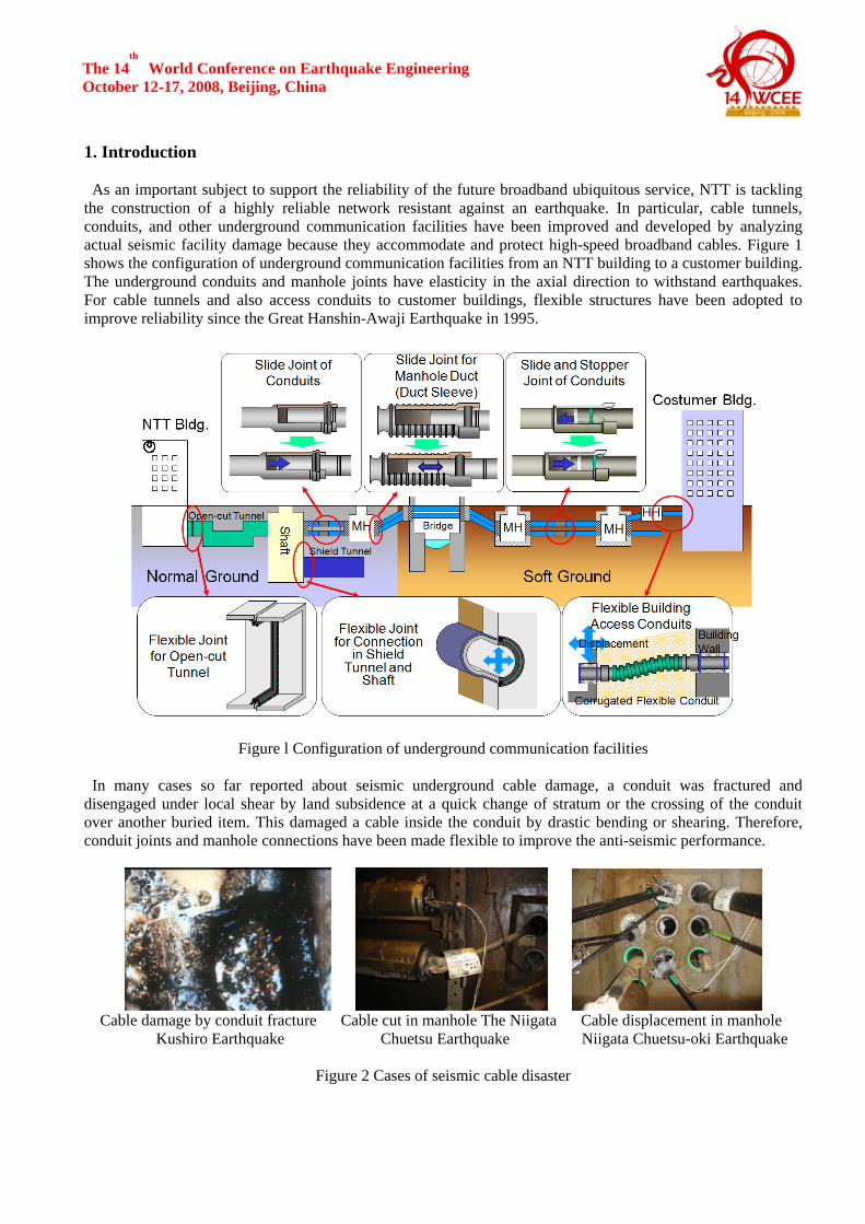
As an important subject to support the reliability of the future broadband ubiquitous service, NTT is tacklingthe construction of a highly reliable network resistant against an earthquake. In particular, cable tunnels,conduits, and other underground communication facilities have been improved and developed by analyzingactual seismic facility damage because they accommodate and protect high-speed broadband cables. Figure 1 shows the configuration of underground communication facilities from an NTT building to a customer building.The underground conduits and manhole joints have elasticity in the axial direction to withstand earthquakes.For cable tunnels and also access conduits to customer buildings, flexible structures have been adopted to improve reliability since the Great Hanshin-Awaji Earthquake in 1995.
Figure l Configuration of underground communication facilities
In many cases so far reported about seismic underground cable damage, a conduit was fractured anddisengaged under local shear by land subsidence at a quick change of stratum or the crossing of the conduitover another buried item. This damaged a cable inside the conduit by drastic bending or shearing. Therefore,conduit joints and manhole connections have been made flexible to improve the anti-seismic performance.
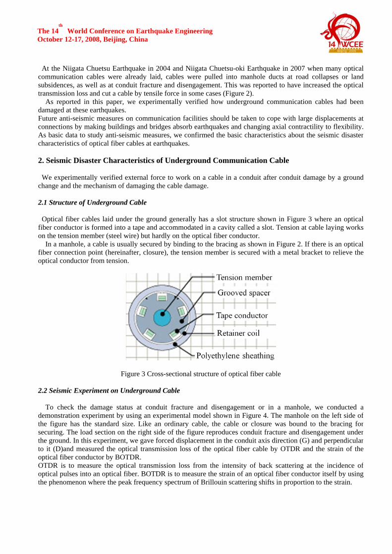
Cable damage by conduit fracture Cable cut in manhole The Niigata Cable displacement in manhole
Kushiro Earthquake Chuetsu Earthquake Niigata Chuetsu-oki Earthquake
Figure 2 Cases of seismic cable disaster
The 14th
World Conference on Earthquake Engineering October 12-17, 2008, Beijing, China
At the Niigata Chuetsu Earthquake in 2004 and Niigata Chuetsu-oki Earthquake in 2007 when many optical communication cables were already laid, cables were pulled into manhole ducts at road collapses or land subsidences, as well as at conduit fracture and disengagement. This was reported to have increased the opticaltransmission loss and cut a cable by tensile force in some cases (Figure 2). As reported in this paper, we experimentally verified how underground communication cables had been damaged at these earthquakes. Future anti-seismic measures on communication facilities should be taken to cope with large displacements at connections by making buildings and bridges absorb earthquakes and changing axial contractility to flexibility. As basic data to study anti-seismic measures, we confirmed the basic characteristics about the seismic disastercharacteristics of optical fiber cables at earthquakes. 2. Seismic Disaster Characteristics of Underground Communication Cable
We experimentally verified external force to work on a cable in a conduit after conduit damage by a groundchange and the mechanism of damaging the cable damage. 2.1 Structure of Underground Cable
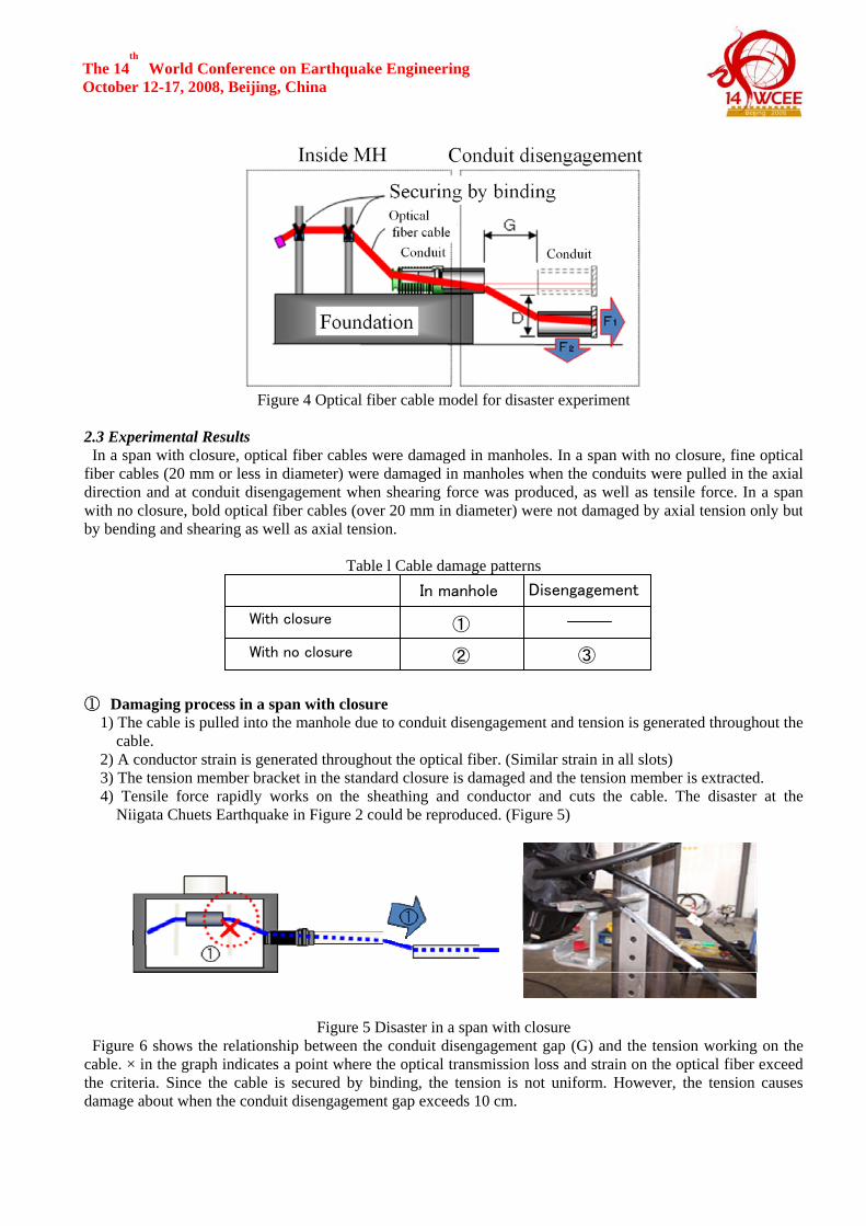
Optical fiber cables laid under the ground generally has a slot structure shown in Figure 3 where an opticalfiber conductor is formed into a tape and accommodated in a cavity called a slot. Tension at cable laying workson the tension member (steel wire) but hardly on the optical fiber conductor. In a manhole, a cable is usually secured by binding to the bracing as shown in Figure 2. If there is an opticalfiber connection point (hereinafter, closure), the tension member is secured with a metal bracket to relieve theoptical conductor from tension.
Figure 3 Cross-sectional structure of optical fiber cable 2.2 Seismic Experiment on Underground Cable To check the damage status at conduit fracture and disengagement or in a manhole, we conducted ademonstration experiment by using an experimental model shown in Figure 4. The manhole on the left side ofthe figure has the standard size. Like an ordinary cable, the cable or closure was bound to the bracing forsecuring. The load section on the right side of the figure reproduces conduit fracture and disengagement under the ground. In this experiment, we gave forced displacement in the conduit axis direction (G) and perpendicularto it (D)and measured the optical transmission loss of the optical fiber cable by OTDR and the strain of theoptical fiber conductor by BOTDR. OTDR is to measure the optical transmission loss from the intensity of back scattering at the incidence ofoptical pulses into an optical fiber. BOTDR is to measure the strain of an optical fiber conductor itself by usingthe phenomenon where the peak frequency spectrum of Brillouin scattering shifts in proportion to the strain.
The 14th
World Conference on Earthquake Engineering October 12-17, 2008, Beijing, China
Figure 4 Optical fiber cable model for disaster experiment
2.3 Experimental Results
In a span with closure, optical fiber cables were damaged in manholes. In a span with no closure, fine optical fiber cables (20 mm or less in diameter) were damaged in manholes when the conduits were pulled in the axialdirection and at conduit disengagement when shearing force was produced, as well as tensile force. In a span with no closure, bold optical fiber cables (over 20 mm in diameter) were not damaged by axial tension only butby bending and shearing as well as axial tension.
Table l Cable damage patterns
① Damaging process in a span with closure 1) The cable is pulled into the manhole due to conduit disengagement and tension is generated throughout the
cable. 2) A conductor strain is generated throughout the optical fiber. (Similar strain in all slots) 3) The tension member bracket in the standard closure is damaged and the tension member is extracted. 4) Tensile force rapidly works on the sheathing and conductor and cuts the cable. The disaster at the
Niigata Chuets Earthquake in Figure 2 could be reproduced. (Figure 5)
Figure 5 Disaster in a span with closure Figure 6 shows the relationship between the conduit disengagement gap (G) and the tension working on the
cable. × in the graph indicates a point where the optical transmission loss and strain on the optical fiber exceedthe criteria. Since the cable is secured by binding, the tension is not uniform. However, the tension causesdamage about when the conduit disengagement gap exceeds 10 cm.
With closure
With no closure
In manhole Disengagement
③ ②
①

The 14th
World Conference on Earthquake Engineering October 12-17, 2008, Beijing, China
Figure 6 ①Conduit disengagement gap and tension Figure 7 ②Conduit disengagement gap and tension ②Damaging process in a manhole in a span with no closure 1) The cable is pulled into the manhole due to conduit disengagement and tension is generated throughout the
cable. 2) The cable comes off from the bracing near the duct and tension works on the far bracing. 3) A conductor strain is generated throughout the optical fiber. (Similar strain in all slots) 4) The strain increases the optical transmission loss or the biting string cuts the conductor. (Figure 8)
Figure 8 Disaster in a manhole in a span with no closure
Figure 7 shows the relationship between disengagement gap (G) and tension (T). As in the previous section,
the tension is not uniform but causes damage about when the disengagement gap exceeds 20 cm. ③Damaging process at conduit disengagement in a span with no closure 1) Same as 1) to 3) in ② 2) As the level difference (D) at conduit disengagement increases, side pressure works on and makes the
cable cross section flat. 3) The side pressure by tension and the abrasion with the conduit edge damage the cable sheathing. 4) The cable slot is crushed and presses the conductor, increasing the optical transmission loss. (Almost
simultaneous occurrence of excessive optical transmission loss, conductor elongation, excessive strain, and boring in sheathing)(Figure 9)
Figure 9 Damage at conduit disengagement in a span with no closure
Figure 10 shows the relationship between the level difference (D) and tension (T) when the disengagement
gap was 10 and 20 cm. Although the tension decreased when strings became loose, the cables were damagedalmost uniformly about when the level difference exceeded 20 cm.

The 14th
World Conference on Earthquake Engineering October 12-17, 2008, Beijing, China
Figure 10 ③ Conduit level difference and tension
2.4 Summary of Underground Cable Disaster Experiment
The cable disaster experiment had complicated factors, such as the loosening and falling of strings, but itsresults can be summarized as follows: In a span with closure, a conduit disengagement gap of about 10 cm caused damage by the pattern of ①. In a span with no closure, fine cables suffered from damage of a combined pattern of ② and ③. Bold optical fiber cables suffered from damage of the pattern of ③. Figures 11 and 12 show the damage areas of fine and boldcables in a span with no closure.
Figure 11 Fine cable damage area Figure 12 Bold cable damage area
3. Basic Characteristics of Optical Fiber Cable An optical fiber cable is not designed resistant to external force. However, the steel wire and polyethylenesheathing may be making the structure resistant to external tension, compressive force, and bending force.Therefore, the optical transmission loss and conductor strain when a communication cable is pulled or bent are checked to clarify the limit of using a communication cable. By clarifying the relationship between cable forceddisplacement and tension and communication fault, the allowable conduit deformation is evaluated. 3.1 Tensile Test of Optical Fiber Cable
As shown in Figure 13, a tensile test was performed by using a hydraulic jack. This test was performed on thesix types of optical fiber cables listed in Table 2. The cables were measured about the limits of load,displacement, strain, and optical transmission loss were measured. The criteria of a seismic disaster wereconductor strain over 2.0% and optical transmission loss over 1.6 dB that would affect the long-term reliability.

The 14th
World Conference on Earthquake Engineering October 12-17, 2008, Beijing, China
Table 2 Optical fiber tensile test conditions
Figure 13 Optical fiber tensile test status
Figure 14 summarizes the relationship between cable tension and optical transmission loss. Irrespective of the
tensile load on the communication cable, the optical transmission loss is constant with almost no change from the initial value, despite dispersion depending on the number of cores. Under tensile force only, the opticaltransmission loss was found not to change until cable fracture by the tension.
Figure 15 the relationship between cable tension, cable strain, and conductor strain about the two cases of SM200 and SM1000. For long-term reliability, the conductor strain limit is considered to be about 0.2%. Untilthe tension member fractures, there is no problem about the conductor strain.
Figure 14 Cable tension and optical Figure 15 Relationship between cable tension, transmission loss cable strain, and conductor strain
3.2 Bending Test of Optical Fiber Cable
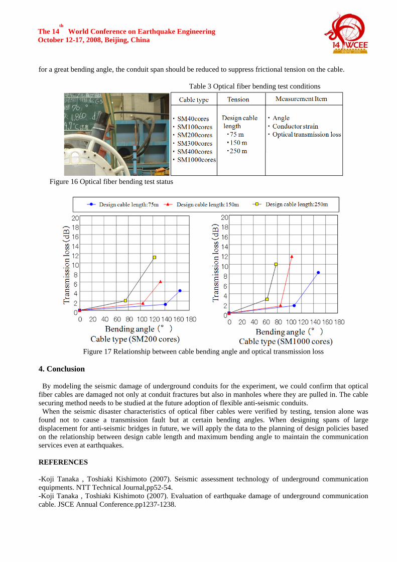
As shown in Figure 16, conduits accommodating optical fiber cables are turned to clarify the relationship between bending angle, optical transmission loss, and conductor strain. This test was performed under themeasuring conditions listed in Table 3.
Under three patterns of frictional tension, each optical fiber cable was checked about the angle where a transmission fault occurred. For the tension patterns, the cable lengths were designed for a crossing angle of 60degrees in a 75-meter span, a 150-meter span, and 250-meter span
Figure 17 shows the relationship between cable bending angle and optical transmission loss about the two
cases of SM200 and SM1000. A transmission loss tends to occur at a bending angle about over 60°, despite dispersion depending on the number of cores.
As the cores of the optical fiber cable are fewer, an optical transmission loss tends to occur at a greaterbending angle. This is advantageous for a fine cable (small number of cores). As the design cable length isshorter, an optical transmission loss tends to occur at a greater bending angle. When the design cable length is 75 meters, an optical transmission loss occurs at a bending angle of about over 100°. At the design of a conduit
The 14th
World Conference on Earthquake Engineering October 12-17, 2008, Beijing, China for a great bending angle, the conduit span should be reduced to suppress frictional tension on the cable.
Table 3 Optical fiber bending test conditions
Figure 16 Optical fiber bending test status
Figure 17 Relationship between cable bending angle and optical transmission loss
4. Conclusion
By modeling the seismic damage of underground conduits for the experiment, we could confirm that optical fiber cables are damaged not only at conduit fractures but also in manholes where they are pulled in. The cablesecuring method needs to be studied at the future adoption of flexible anti-seismic conduits.
When the seismic disaster characteristics of optical fiber cables were verified by testing, tension alone wasfound not to cause a transmission fault but at certain bending angles. When designing spans of largedisplacement for anti-seismic bridges in future, we will apply the data to the planning of design policies basedon the relationship between design cable length and maximum bending angle to maintain the communicationservices even at earthquakes. REFERENCES -Koji Tanaka , Toshiaki Kishimoto (2007). Seismic assessment technology of underground communicationequipments. NTT Technical Journal,pp52-54. -Koji Tanaka , Toshiaki Kishimoto (2007). Evaluation of earthquake damage of underground communicationcable. JSCE Annual Conference.pp1237-1238.