experiment - mit opencourseware · 2.76 multi-scale sy g g experiment be careful with the magnets!!...
TRANSCRIPT
2.76 Multi-scale Sy g g
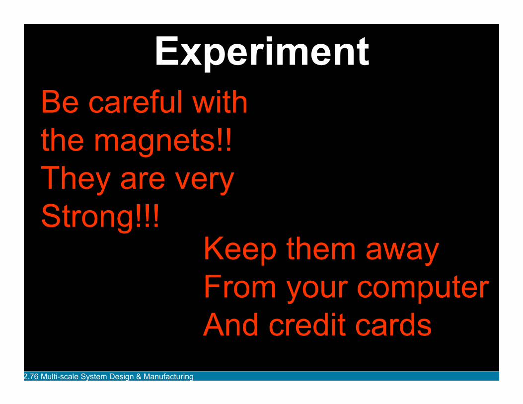
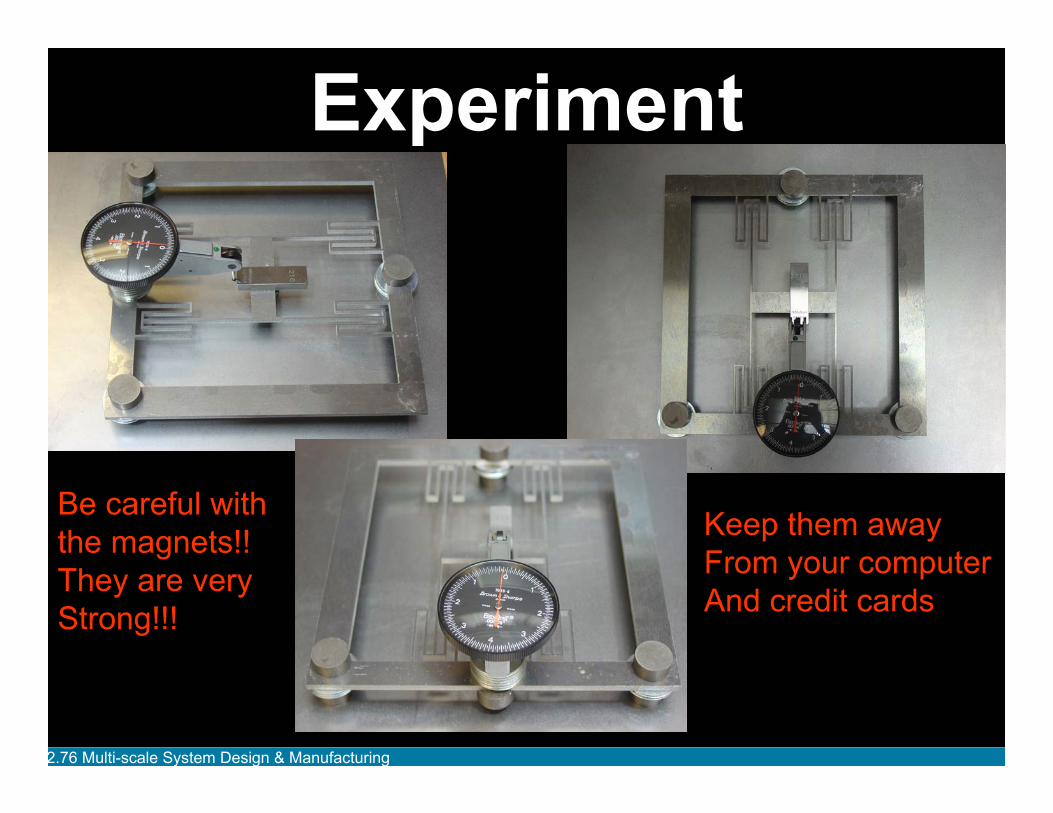
Experiment Be careful with the magnets!! They are very Strong!!!
Keep them away From your computer And credit cards
stem Desi n & Manufacturin
2.76 / 2.760 Lecture 3: Large scale Flexure experiment
Constraints
Micro-fabrication
Micro-physics scaling
Assignment
2.76 Multi-scale Sy g gstem Desi n & Manufacturin
2.76 Multi-scale Sy g g
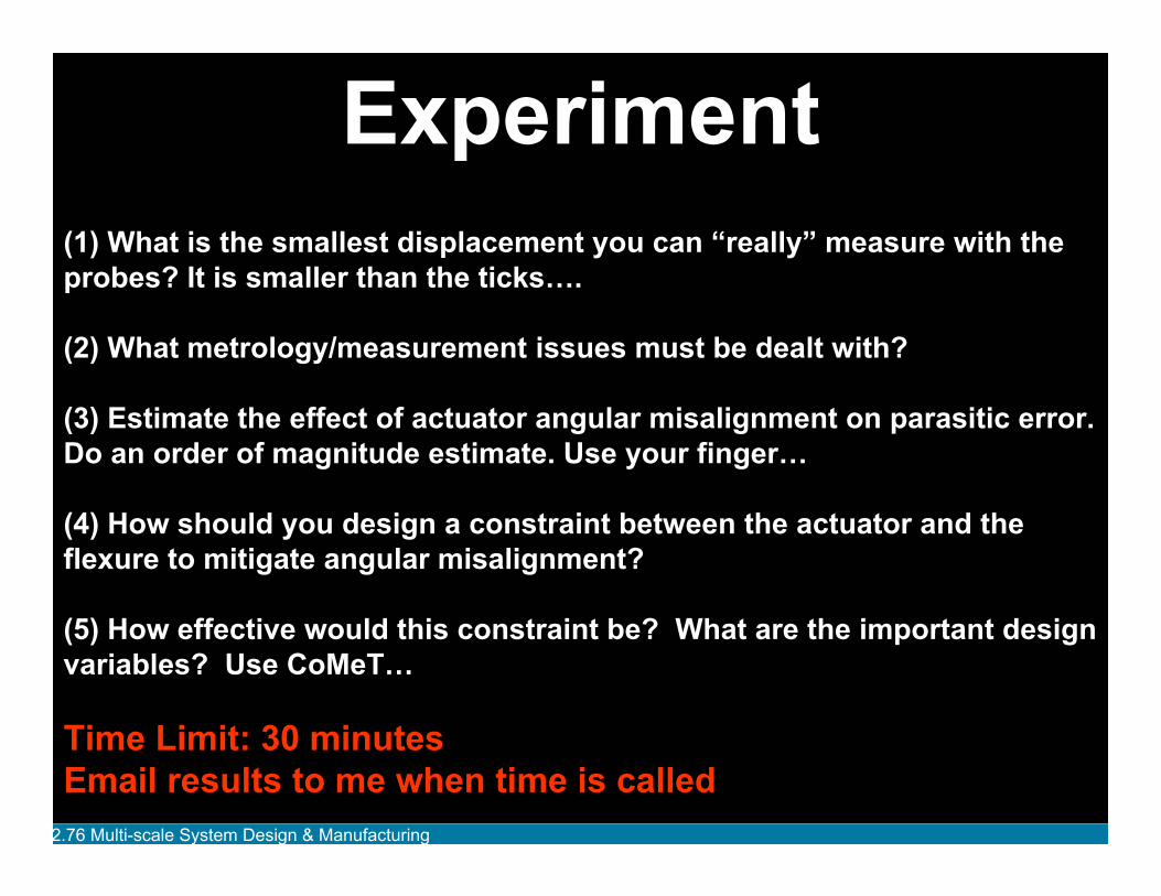
Experiment probes? It is smaller than the ticks….
(4) How should you design a constraint between the actuator and the flexure to mitigate angular misalignment?
What are the important design variables? Use CoMeT…
Time Limit: 30 minutes Email results to me when time is called
stem Desi n & Manufacturin
(1) What is the smallest displacement you can “really” measure with the
(2) What metrology/measurement issues must be dealt with?
(3) Estimate the effect of actuator angular misalignment on parasitic error. Do an order of magnitude estimate. Use your finger…
(5) How effective would this constraint be?
2.76 Multi-scale Sy g g
Experiment
Be careful with the magnets!! They are very Strong!!!
Keep them away From your computer And credit cards
stem Desi n & Manufacturin
2.76 Multi-scale Sy g g
Discussion Metrology/measurement issues
Actuator angular misalignment on parasitic error
Effectiveness of constraint between actuator-flexure
stem Desi n & Manufacturin
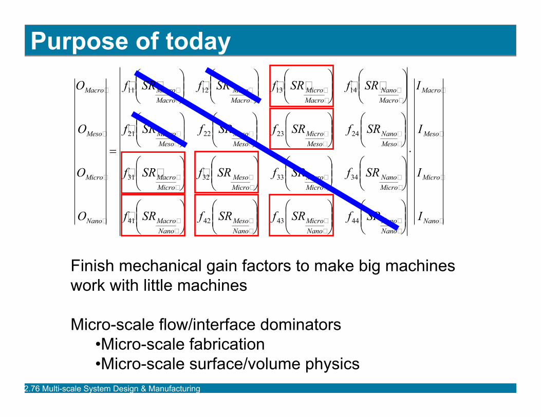
Purpose of today OMacro
OMeso
OMicro
ONano
⋅
⎞⎟⎟⎠
⎞⎟⎟⎠
⎞⎟⎟⎠
⎞⎟⎟⎠Nano
Nano Nano Micro
Nano Meso
Nano Macro
Micro Nano
Micro Micro
Micro Meso
Micro Macro
Meso Nano
Meso Micro
Meso Meso
Meso Macro
Macro Nano
Macro Micro
Macro Meso
Macro Macro
SRfSRfSRfSRf
SRfSRfSRf
SRfSRfSRfSRf
SRf
⎜⎜ ⎝
⎛ ⎟⎟ ⎠
⎞ ⎜⎜ ⎝
⎛ ⎟⎟ ⎠
⎞ ⎜⎜ ⎝
⎛ ⎟⎟ ⎠
⎞ ⎜⎜ ⎝
⎛
⎜⎜ ⎝
⎛ ⎟⎟ ⎠
⎞ ⎜⎜ ⎝
⎛ ⎟⎟ ⎠
⎞ ⎜⎜ ⎝
⎛ ⎟⎟ ⎠
⎞ ⎜⎜ ⎝
⎛
⎜⎜ ⎝
⎛ ⎟⎟ ⎠
⎞ ⎜⎜ ⎝
⎛ ⎟⎟ ⎠
⎞ ⎜⎜ ⎝
⎛ ⎟⎟ ⎠
⎞ ⎜⎜ ⎝
⎛
⎜⎜ ⎝
⎛ ⎟⎟ ⎠
⎞ ⎜⎜ ⎝
⎛ ⎟⎟ ⎠
⎞ ⎜⎜ ⎝
⎛ ⎟⎟ ⎠
⎞ ⎜⎜ ⎝
⎛
44434241
34333231
24232221
14131211
SR f
SR f SR f SR f
=
IMacro
IMeso
IMicro
I Nano
Finish mechanical gain factors to make big machines work with little machines
Micro-scale flow/interface dominators •Micro-scale fabrication•Micro-scale surface/volume physics
2.76 Multi-scale Sy g gstem Desi n & Manufacturin
Constraints
2.76 Multi-scale System Design & Manufacturing
2.76 Multi-scale Sy g g
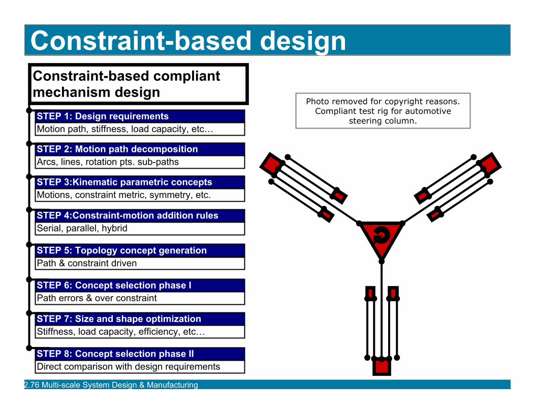
Constraint-based design Constraint-based compliant mechanism design
Serial, parallel, hybrid
Path errors & over constraint
steering column.
stem Desi n & Manufacturin
STEP 2: Motion path decomposition
STEP 3:Kinematic parametric concepts
STEP 4:Constraint-motion addition rules
STEP 5: Topology concept generation
STEP 6: Concept selection phase I
STEP 7: Size and shape optimization
STEP 8: Concept selection phase II
STEP 1: Design requirements
Arcs, lines, rotation pts. sub-paths
Motions, constraint metric, symmetry, etc.
Path & constraint driven
Stiffness, load capacity, efficiency, etc…
Direct comparison with design requirements
Motion path, stiffness, load capacity, etc…
Photo removed for copyright reasons. Compliant test rig for automotive
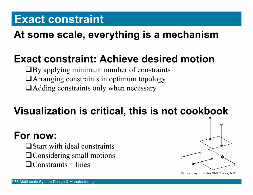
Exact constraint At some scale, everything is a mechanism
Exact constraint: Achieve desired motion�By applying minimum number of constraints�Arranging constraints in optimum topology�Adding constraints only when necessary
Visualization is critical, this is not cookbook
For now: �Start with ideal constraints�Considering small motions�Constraints = lines
Figure: Layton Hales PhD Thesis, MIT.
2.76 Multi-scale Sy g gstem Desi n & Manufacturin
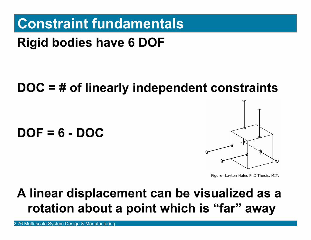
Constraint fundamentals Rigid bodies have 6 DOF
DOC = # of linearly independent constraints
DOF = 6 - DOC
Figure: Layton Hales PhD Thesis, MIT.
A linear displacement can be visualized as a rotation about a point which is “far” away
2.76 Multi-scale Sy g gstem Desi n & Manufacturin
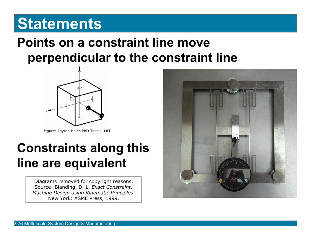
Statements Points on a constraint line move
perpendicular to the constraint line
Figure: Layton Hales PhD Thesis, MIT.
Constraints along this line are equivalent
2.76 Multi-scale Sy g g
Source: Blanding, D. L. Exact Constraint: .
stem Desi n & Manufacturin
Diagrams removed for copyright reasons.
Machine Design using Kinematic PrinciplesNew York: ASME Press, 1999.
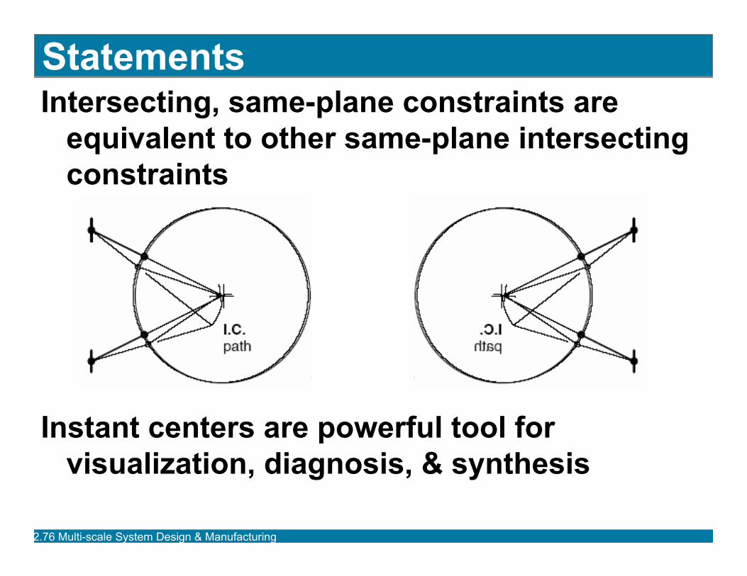
Statements Intersecting, same-plane constraints are
equivalent to other same-plane intersecting constraints
Instant centers are powerful tool for visualization, diagnosis, & synthesis
2.76 Multi-scale Sy g gstem Desi n & Manufacturin
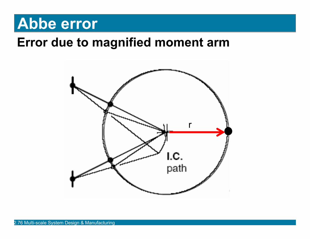
Abbe error Error due to magnified moment arm
r
2.76 Multi-scale Sy g gstem Desi n & Manufacturin
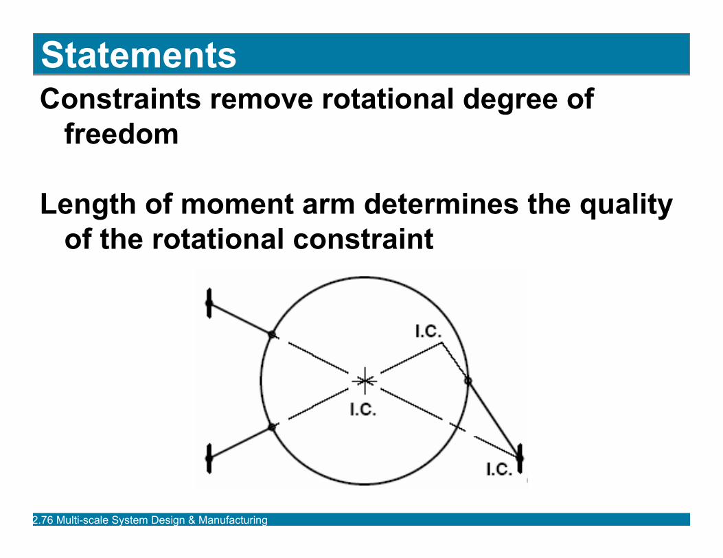
Statements Constraints remove rotational degree of
freedom
Length of moment arm determines the quality of the rotational constraint
2.76 Multi-scale Sy g gstem Desi n & Manufacturin

Statements Parallel constraints may be visualized/treated
as intersecting at infinity
2.76 Multi-scale Sy g gstem Desi n & Manufacturin
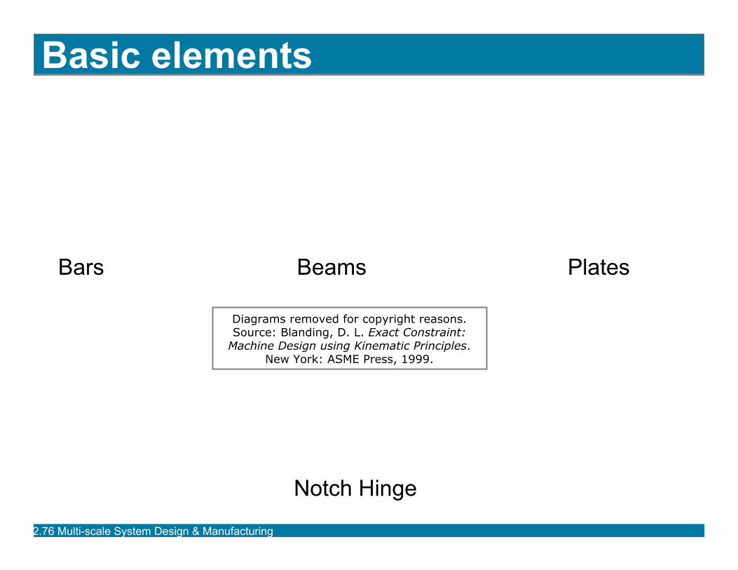
Basic elements
Bars Beams Plates
Diagrams removed for copyright reasons. Source: Blanding, D. L. Exact Constraint:
Machine Design using Kinematic Principles. New York: ASME Press, 1999.
Notch Hinge
2.76 Multi-scale Sy g gstem Desi n & Manufacturin
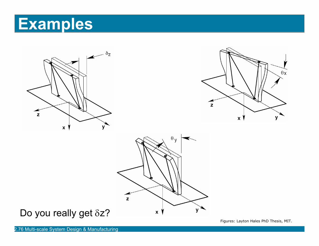
Examples
Do you really get δz? Figures: Layton Hales PhD Thesis, MIT.
2.76 Multi-scale Sy g gstem Desi n & Manufacturin
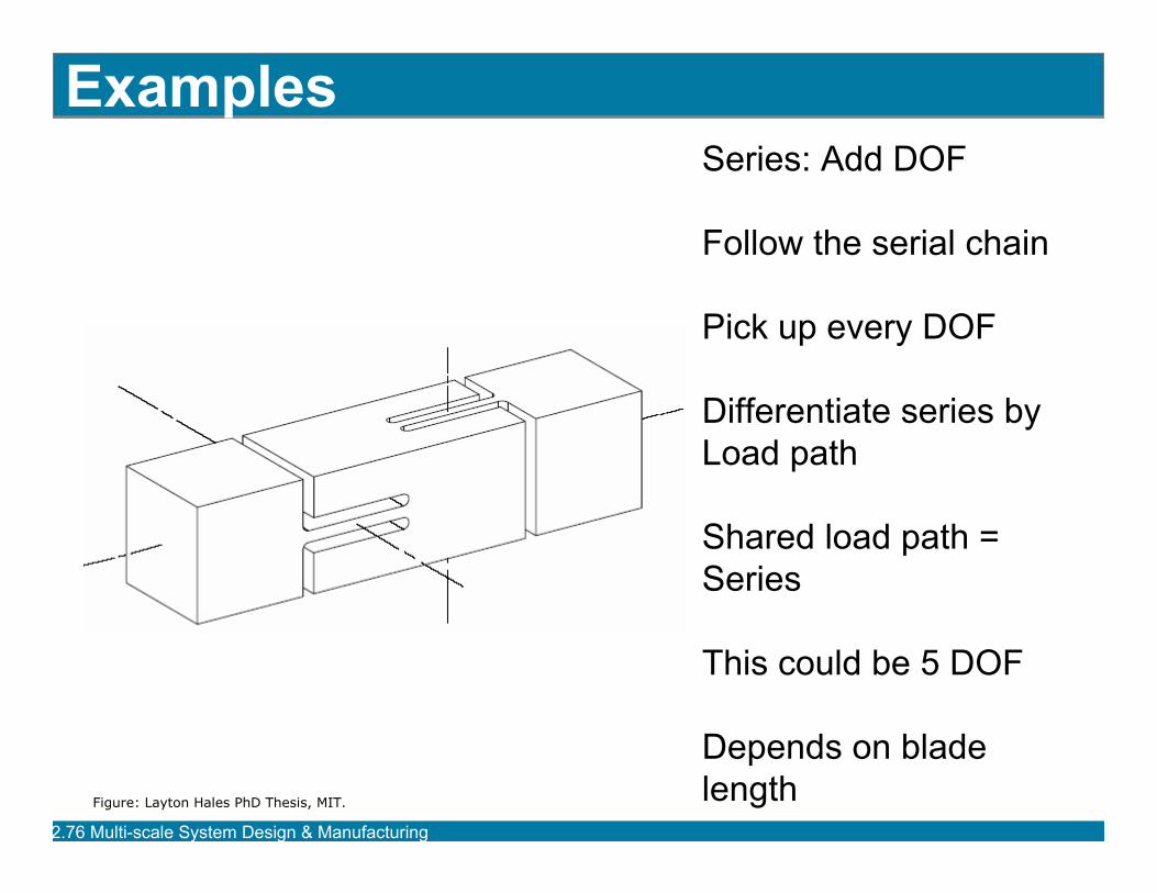
Examples Series: Add DOF
Follow the serial chain
Pick up every DOF
Differentiate series by Load path
Shared load path = Series
This could be 5 DOF
Depends on blade lengthFigure: Layton Hales PhD Thesis, MIT.
2.76 Multi-scale Sy g gstem Desi n & Manufacturin
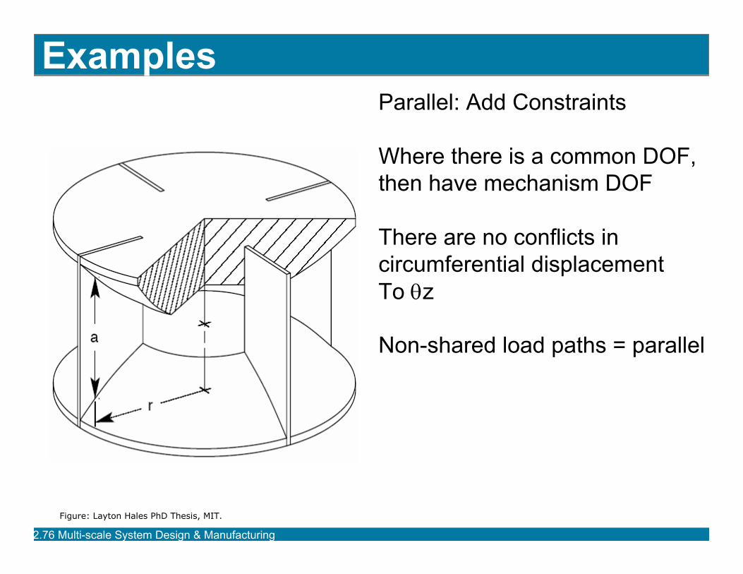
Examples Parallel: Add Constraints
Where there is a common DOF, then have mechanism DOF
There are no conflicts in circumferential displacement To θz
Non-shared load paths = parallel
Figure: Layton Hales PhD Thesis, MIT.
2.76 Multi-scale Sy g gstem Desi n & Manufacturin
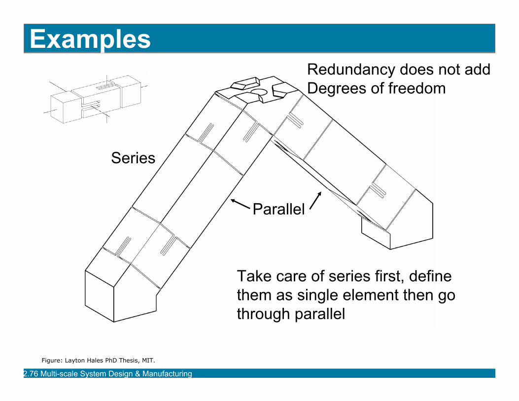
Examples
Take care of series first, define them as single element then go through parallel
Series
Parallel
Redundancy does not add Degrees of freedom
Figure: Layton Hales PhD Thesis, MIT.
2.76 Multi-scale Sy g gstem Desi n & Manufacturin
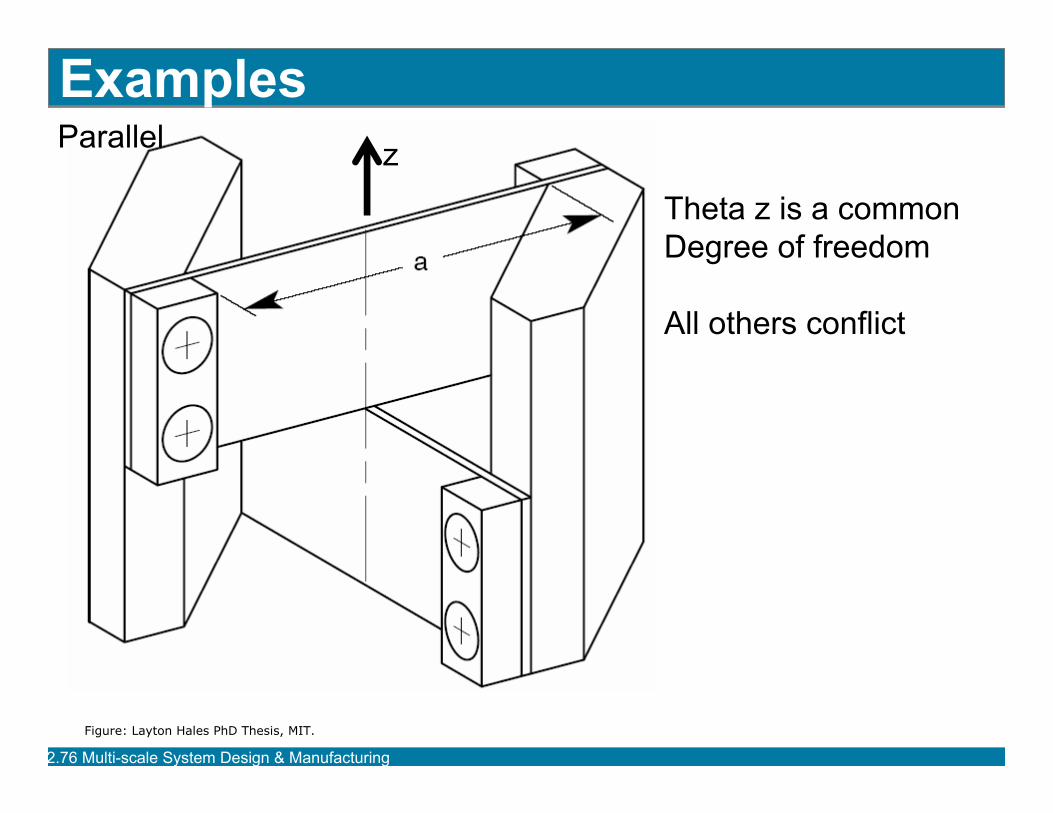
Examples
Theta z is a common Degree of freedom
All others conflict
z Parallel
Figure: Layton Hales PhD Thesis, MIT.
2.76 Multi-scale Sy g gstem Desi n & Manufacturin
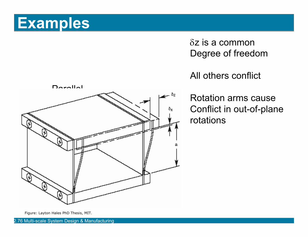
Examples δz is a common Degree of freedom
All others conflict Parallel
Rotation arms cause Conflict in out-of-plane rotations
Figure: Layton Hales PhD Thesis, MIT.
2.76 Multi-scale Sy g gstem Desi n & Manufacturin
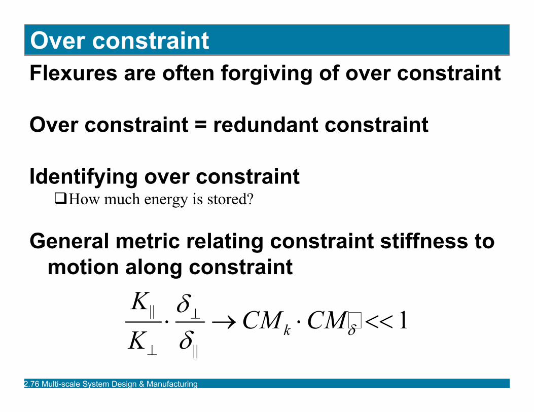
Over constraint Flexures are often forgiving of over constraint
Over constraint = redundant constraint
Identifying over constraint �How much energy is stored?
General metric relating constraint stiffness to motion along constraint
|| ⋅δ⊥ → CM
KK
CM << 1⋅k δ ⊥ δ ||
2.76 Multi-scale Sy g gstem Desi n & Manufacturin
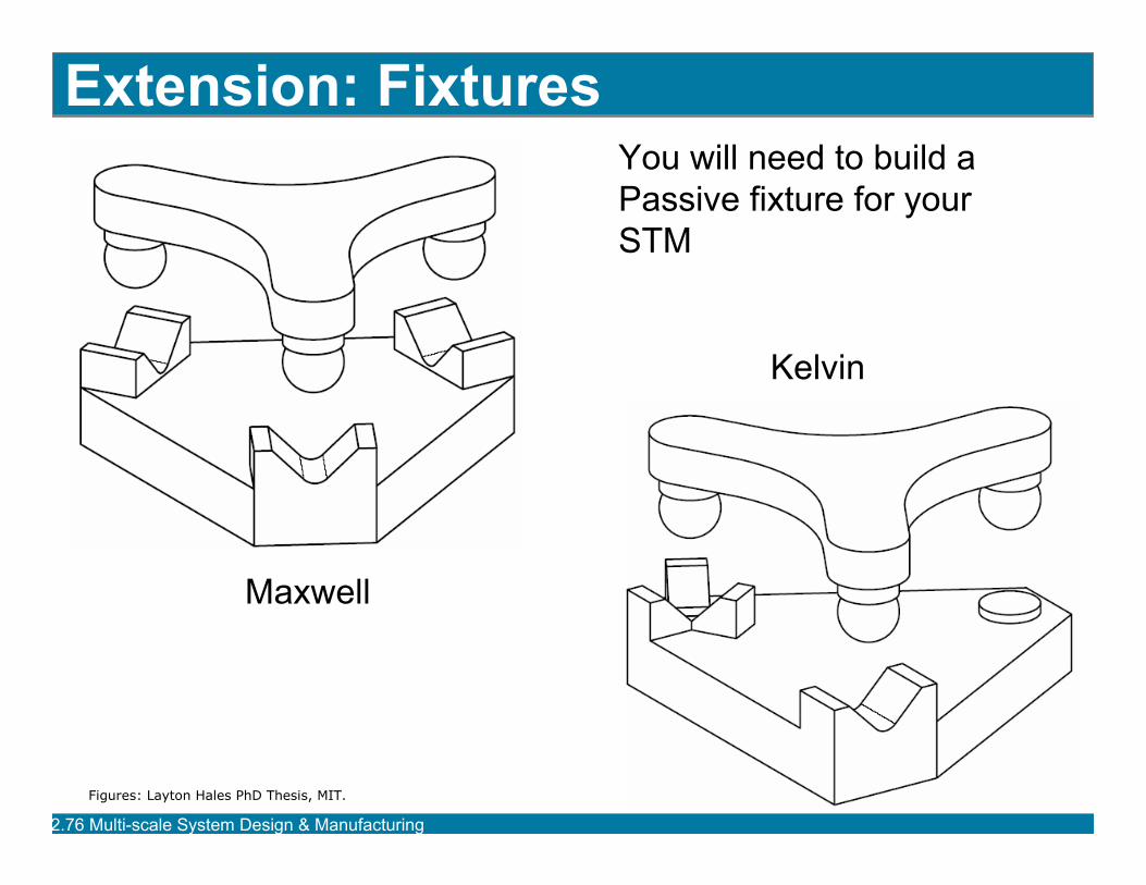
Extension: Fixtures You will need to build a Passive fixture for your STM
Kelvin
Maxwell
Figures: Layton Hales PhD Thesis, MIT.
2.76 Multi-scale Sy g gstem Desi n & Manufacturin
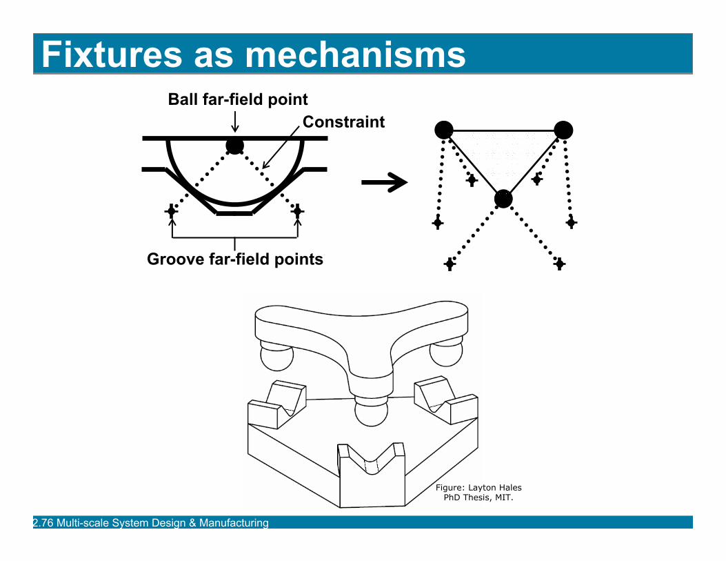
Fixtures as mechanisms Ball far-field point
Groove far-field points
Constraint
Figure: Layton Hales PhD Thesis, MIT.
2.76 Multi-scale Sy g gstem Desi n & Manufacturin
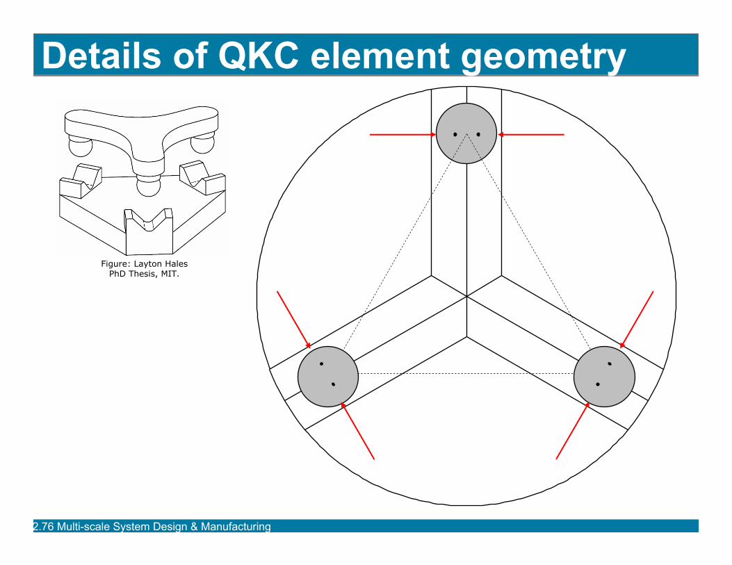
Details of QKC element geometry
Figure: Layton Hales PhD Thesis, MIT.
2.76 Multi-scale Sy g gstem Desi n & Manufacturin
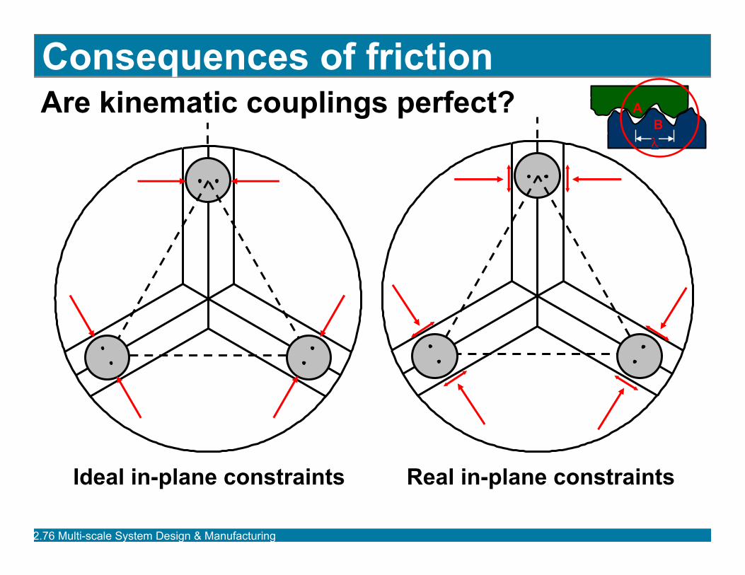
Are kinematic couplings perfect? Consequences of friction
B A
λ
Ideal in-plane constraints Real in-plane constraints
2.76 Multi-scale Sy g gstem Desi n & Manufacturin
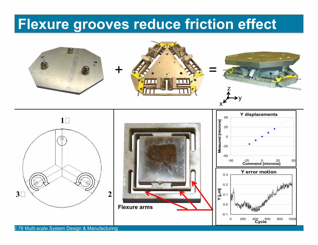
Flexure grooves reduce friction effect
+ =
y x
z
2.76 Multi-scale Sy g g
1
23
-50
-25
0
25
50
-50 0 [
[]
0.0
0.1
0.2
0.3
0Y
[ µm
]
stem Desi n & Manufacturin
Flexure arms
Y displacements
-25 25 50 Command microns]
Mea
sure
dm
icro
ns
Y error motion
-0.1 200 400 600 800 1000
Cycle
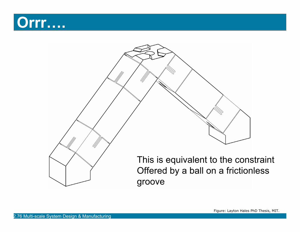
Orrr….
This is equivalent to the constraint Offered by a ball on a frictionless groove
Figure: Layton Hales PhD Thesis, MIT.
2.76 Multi-scale Sy g gstem Desi n & Manufacturin
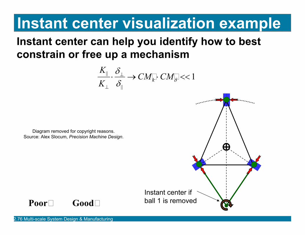
Instant center visualization example Instant center can help you identify how to best constrain or free up a mechanism
|| ⋅δ⊥ → CM
⊥
KK
CM << 1⋅k δδ ||
ball 1 is removed
Diagram removed for copyright reasons. Source: Alex Slocum, Precision Machine Design.
Instant center if Poor Good
2.76 Multi-scale Sy g gstem Desi n & Manufacturin
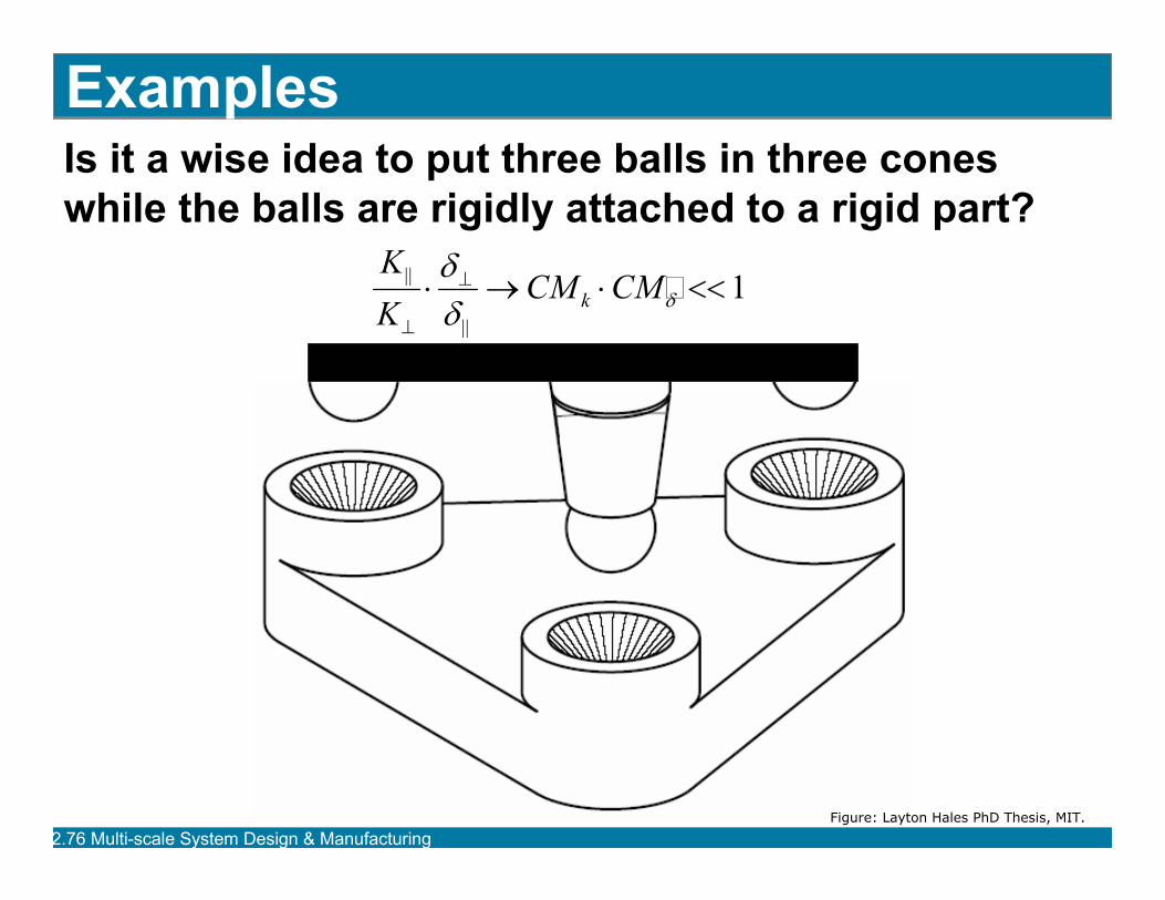
Examples Is it a wise idea to put three balls in three cones while the balls are rigidly attached to a rigid part?
|| ⋅δ⊥ → CM
KK
CM << 1⋅k δδ ||⊥
Figure: Layton Hales PhD Thesis, MIT.
2.76 Multi-scale Sy g gstem Desi n & Manufacturin
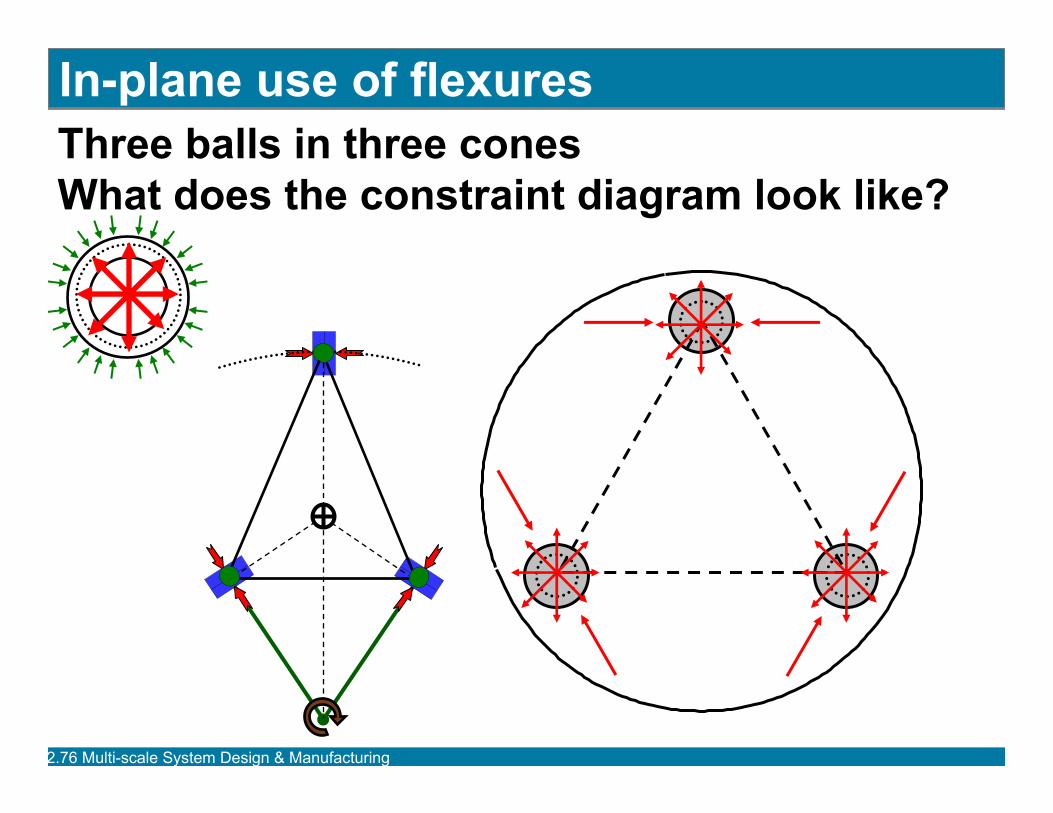
In-plane use of flexures Three balls in three conesWhat does the constraint diagram look like?
2.76 Multi-scale Sy g gstem Desi n & Manufacturin
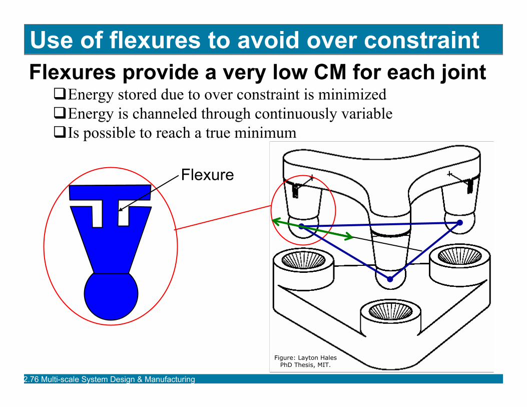
Use of flexures to avoid over constraint Flexures provide a very low CM for each joint�Energy stored due to over constraint is minimized�Energy is channeled through continuously variable�Is possible to reach a true minimum
Flexure
Figure: Layton Hales PhD Thesis, MIT.
2.76 Multi-scale Sy g gstem Desi n & Manufacturin
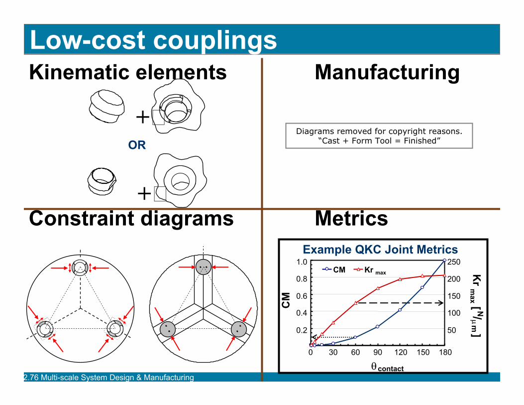
2.76 Multi-scale Sy g g
Kinematic elements Manufacturing
Constraint diagrams Metrics
+
+
OR
Low-cost couplings
Example QKC Joint Metrics
0.2
0.4
0.6
0.8
1.0
0 150
θcontact
CM
50
100
150
200
250
Kr m
ax [ N/ µ m
]
CM Kr
stem Desi n & Manufacturin
30 60 90 120 180
max
Diagrams removed for copyright reasons. “Cast + Form Tool = Finished”
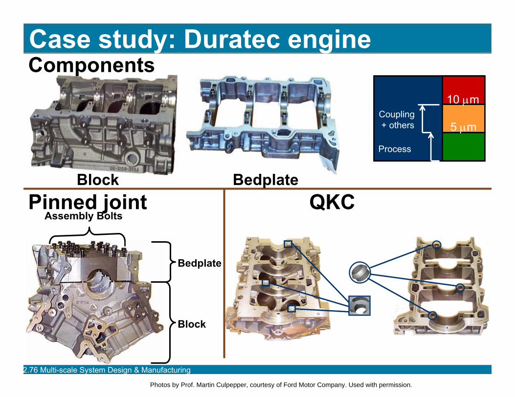
Components
Pinned joint
Block
Assembly Bolts
Case study: Duratec engine
Block
Coupling + others
Process
10 µm
5 µm
QKC
Bedplate
Bedplate
2.76 Multi-scale Sy g gstem Desi n & Manufacturin
Photos by Prof. Martin Culpepper, courtesy of Ford Motor Company. Used with permission.
2.76 Multi-scale Sy g g
Micro-scale systems
stem Desi n & Manufacturin
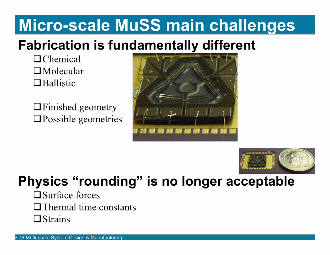
Micro-scale MuSS main challenges Fabrication is fundamentally different�Chemical�Molecular�Ballistic
�Finished geometry�Possible geometries
Physics “rounding” is no longer acceptable�Surface forces�Thermal time constants�Strains
2.76 Multi-scale Sy g gstem Desi n & Manufacturin
2.76 Multi-scale Sy g g
Micro-fabrication video
stem Desi n & Manufacturin

General process
Deposition •Oxidation or •Deposition
Lithography •Add resist •Transfer pattern •Remove resist
Etch •Wet isotropic or •Wet anisotropic or •RIE
DevicesWafers
Bulk micromachining = Removal of the wafer
Surface micromachining = Add/remove layers 2.76 Multi-scale Sy g gstem Desi n & Manufacturin
2.76 Multi-scale Sy g g
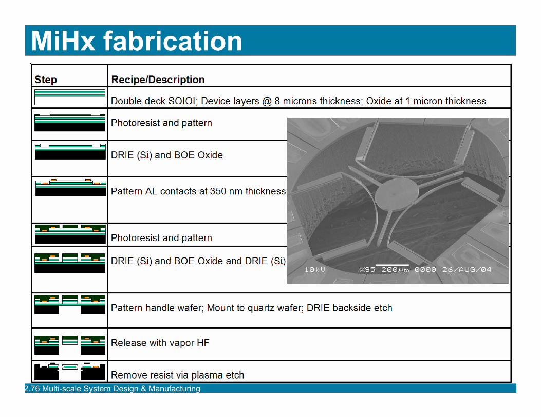
MiHx fabrication
stem Desi n & Manufacturin
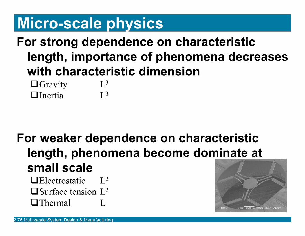
Micro-scale physics For strong dependence on characteristic
length, importance of phenomena decreases with characteristic dimension �Gravity L3
�Inertia L3
For weaker dependence on characteristic length, phenomena become dominate at small scale �Electrostatic L2
�Surface tension L2
�Thermal L
2.76 Multi-scale Sy g gstem Desi n & Manufacturin
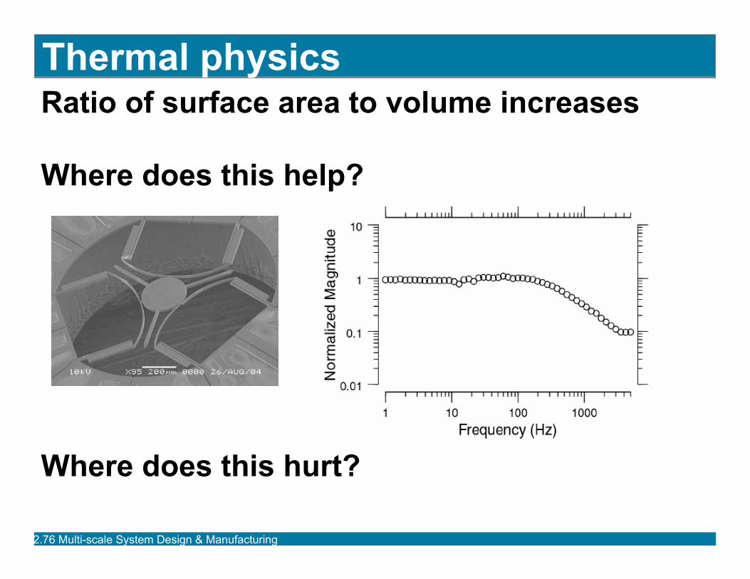
Thermal physics Ratio of surface area to volume increases
Where does this help?
Where does this hurt?
2.76 Multi-scale Sy g gstem Desi n & Manufacturin
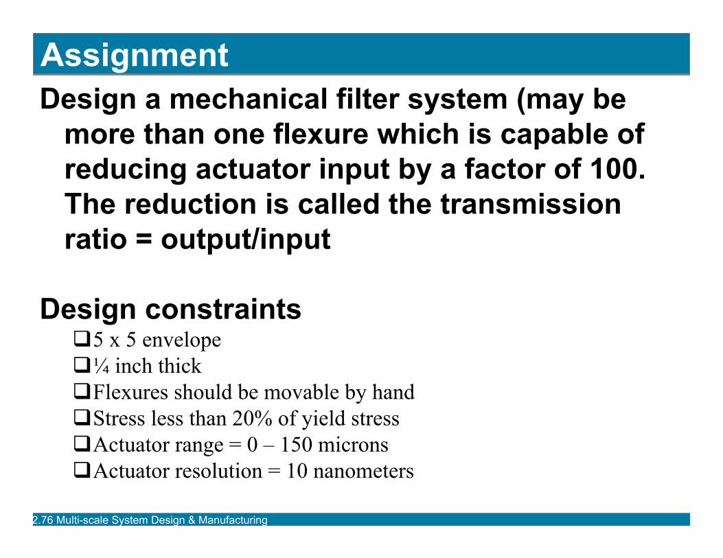
Assignment Design a mechanical filter system (may be
more than one flexure which is capable of reducing actuator input by a factor of 100. The reduction is called the transmission ratio = output/input
Design constraints�5 x 5 envelope�¼ inch thick�Flexures should be movable by hand�Stress less than 20% of yield stress�Actuator range = 0 – 150 microns�Actuator resolution = 10 nanometers
2.76 Multi-scale Sy g gstem Desi n & Manufacturin