experiment (4): flow measurement...
TRANSCRIPT
Fluid Mechanics Lab Experiment (4): Flow measurement
Instructors : Dr. Khalil M. ALASTAL Eng. Mohammed Y. Mousa 1
Experiment (4): Flow measurement
Introduction:
The flow measuring apparatus is used to familiarize the students with typical methods of flow measurement of an incompressible fluid and, at the same time demonstrate applications of the Bernoulli's equation. The flow is determined using a sudden enlargement, venturi meter, orifice plate, elbow and a
rotameter. The pressure drop associated with each meter is measured directly from the
manometers.
Purpose:
To investigate the flow rate using particular flow measuring apparatus.
Apparatus:
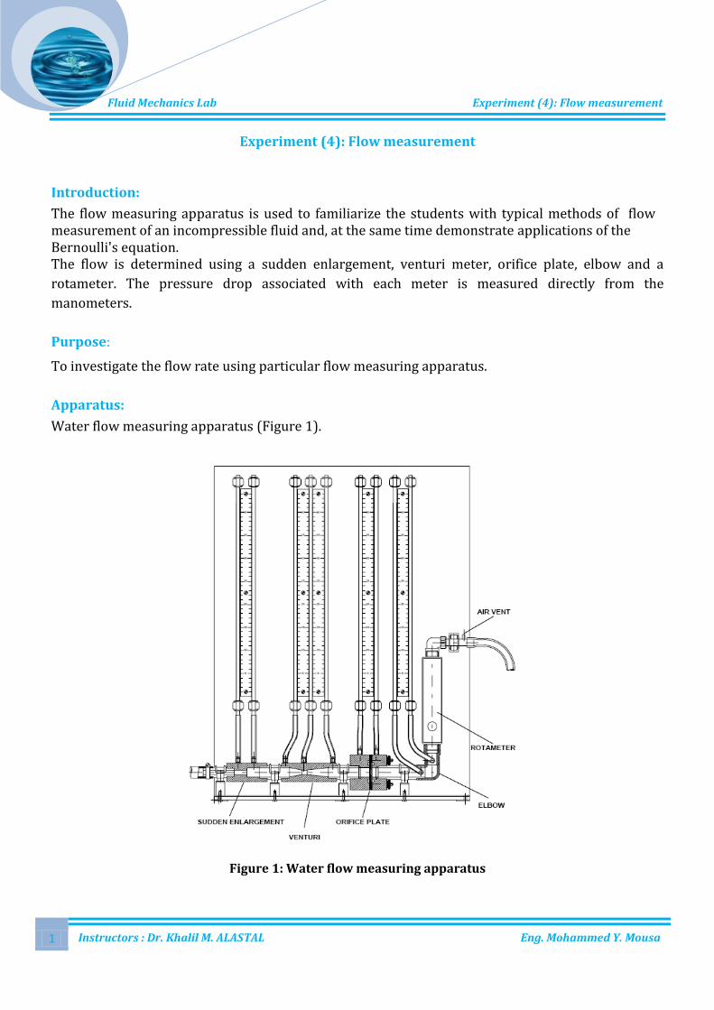
Water flow measuring apparatus (Figure 1).
Figure 1: Water flow measuring apparatus

Fluid Mechanics Lab Experiment (4): Flow measurement
Instructors : Dr. Khalil M. ALASTAL Eng. Mohammed Y. Mousa 2
Water flow measuring apparatus is designed as a free-standing apparatus for use on the hydraulics bench, although it could be used in conjunction with a low pressure water supply controlled by a valve and a discharge to drain. Water enters the apparatus through the lower left-hand end and flows horizontally through a sudden enlargement into a transparent venturi meter, and into an orifice plate, a 90° elbow changes the flow direction to vertical and connects to a variable area flow meter, a second bend passes the flow into a discharge pipe which incorporates an atmospheric break. The static head at various points in the flow path may be measured on a manometer panel. The water flow through the apparatus is controlled by the delivery valve of the hydraulics bench and the flow rate may be confirmed by using the volumetric measuring tank of the hydraulics bench.
Theory:
(1) Pressure drop at sudden enlargement
The test section consists of a 10mm diameter bore with a sudden enlargement to 20mm diameter. Two manometer are provided. Consider a sudden enlargement in pipe flow area from area A1 to area A2. Applying Newton’s second law, the net force acting on the fluid equals the rate of increase of momentum
Where P' is the mean pressure of the eddying fluid over the annular area of the expansion. It is known from experimental evidence that P´ = P1, since the jet issuing from the smaller pipe is essentially parallel
From Bernoulli equation:
Since the flow direction is horizontal

Fluid Mechanics Lab Experiment (4): Flow measurement
Instructors : Dr. Khalil M. ALASTAL Eng. Mohammed Y. Mousa 3
and substituting from Newton’s second law:
Using Bernoulli equation:
but by continuity equation then:

Fluid Mechanics Lab Experiment (4): Flow measurement
Instructors : Dr. Khalil M. ALASTAL Eng. Mohammed Y. Mousa 4
Where is the coefficient of discharge.
(2) The venturi meter
The venturi is manufactured from transparent acrylic materials and follows the classic 21°-10° convergent-divergent design which forms the basis of most engineering standards for venturi flow meters. From consideration of continuity between the mouth of the venturi of area A1 and the throat of area A2:
and on introducing the diameter ratio then:
Applying Bernoulli’s theorem to the venturi meter between section 1 and section 2, neglecting losses and assuming the venturi is installed horizontally:
Fluid Mechanics Lab Experiment (4): Flow measurement
Instructors : Dr. Khalil M. ALASTAL Eng. Mohammed Y. Mousa 5
Rearranging:
and solving for :
The volumetric flow rate is then given by:
The actual discharge will be less than this due to losses causing the velocity through the throat to be less than that predicted by Bernoulli’s theorem, therefore it is necessary to introduce an experimentally determined coefficient of discharge . The actual discharge will then be given by:
The coefficient of discharge varies with both the Reynolds number and area ratio. Typical values for a machined venturi meter are between 0.975 and 0.995.
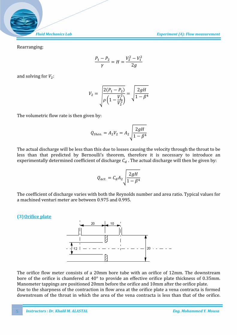
(3) Orifice plate
The orifice flow meter consists of a 20mm bore tube with an orifice of 12mm. The downstream bore of the orifice is chamfered at 40° to provide an effective orifice plate thickness of 0.35mm. Manometer tappings are positioned 20mm before the orifice and 10mm after the orifice plate. Due to the sharpness of the contraction in flow area at the orifice plate a vena contracta is formed downstream of the throat in which the area of the vena contracta is less than that of the orifice.

Fluid Mechanics Lab Experiment (4): Flow measurement
Instructors : Dr. Khalil M. ALASTAL Eng. Mohammed Y. Mousa 6
Applying the continuity equation between the upstream conditions of area A1 and the vena contracta of area Ac:
Where suffix c denotes the vena contracta.
Applying Bernoulli’s equation, neglecting losses and assuming a horizontal installation:
Rearranging:
and solving for :
The volumetric flow rate is then given by:
The flow area at the vena contracta is not known and therefore a coefficient of contraction may be introduced so that
The coefficient of contraction will be included in the coefficient of discharge and the equations rewritten in terms of the orifice area A2 with any uncertainties and errors eliminated by the experimental determination of the coefficient of discharge. The volumetric flow rate is then given by:

Fluid Mechanics Lab Experiment (4): Flow measurement
Instructors : Dr. Khalil M. ALASTAL Eng. Mohammed Y. Mousa 7
The position of the manometer tappings has a small effect on the values of the discharge coefficients which also vary with area ratio, with pipe size and with Reynolds number. The variations of with Reynolds number is tabulated below for orifice plates with .
Reynolds Number
1 x 10⁴ 2 x 10⁴ 3 x 10⁴ 5 x 10⁴ 7 x 10⁴ 1 x 10⁵ 3 x 10⁵ 1 x 10⁶ 1 x 10⁷
D & D/2 taps
0.6127 0.6102 0.6079 0.6068 0.6060 0.6043 0.6036 0.6032
(4) Flow Round Bends and Elbows
A 90º elbow is placed immediately after the orifice plate and before the rotameter. There is a constant bore diameter throughout the bend with manometer tappings positioned normal to the plane of the bend before and after the elbow. Whenever the direction of the flow is changed at a bend or elbow, the velocity distribution across the pipe is disturbed. A centrifugal effect causes the maximum velocity to occur towards the outside of the bend or elbow whilst at the inside of the bend or elbow, the flow is slowed or even reversed in direction if the flow separates from the wall and a vena-contracta formed. A secondary flow is set up at right angles to the pipe cross section which increases the velocity gradient and hence the shear stress of the wall. The loss of head is related to the velocity head by defining a bend loss coefficient so that
Values of are related to the pipe friction factors or by a constant which is dependent on the ratio of the bend radius to the pipe diameter R/D. This constant may also be treated as an equivalent length of straight pipe expressed as diameters by using the Darcy Weisbach equation :
hence
Fluid Mechanics Lab Experiment (4): Flow measurement
Instructors : Dr. Khalil M. ALASTAL Eng. Mohammed Y. Mousa 8
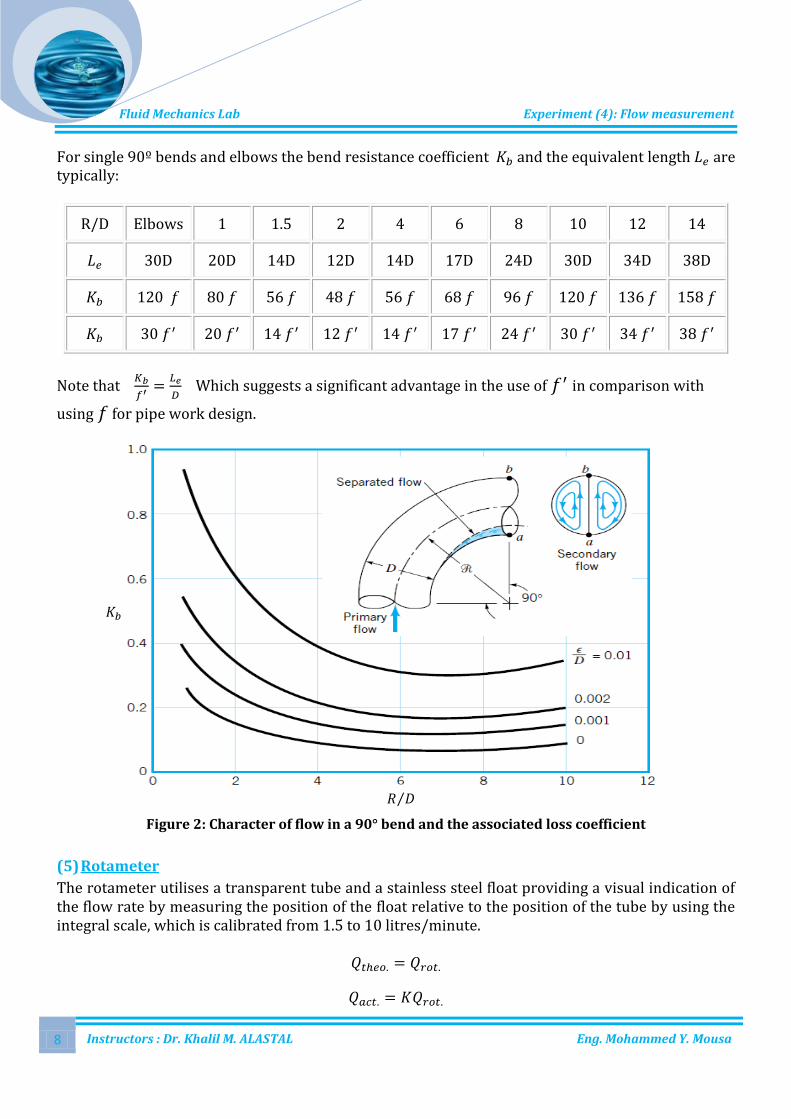
For single 90º bends and elbows the bend resistance coefficient and the equivalent length are typically:
R/D Elbows 1 1.5 2 4 6 8 10 12 14
30D 20D 14D 12D 14D 17D 24D 30D 34D 38D
120 80 56 48 56 68 96 120 136 158
30 20 14 12 14 17 24 30 34 38
Note that
Which suggests a significant advantage in the use of in comparison with
using for pipe work design.
Figure 2: Character of flow in a 90° bend and the associated loss coefficient
(5) Rotameter
The rotameter utilises a transparent tube and a stainless steel float providing a visual indication of the flow rate by measuring the position of the float relative to the position of the tube by using the integral scale, which is calibrated from 1.5 to 10 litres/minute.

Fluid Mechanics Lab Experiment (4): Flow measurement
Instructors : Dr. Khalil M. ALASTAL Eng. Mohammed Y. Mousa 9
Procedures:
1. Position the water flow measuring apparatus on the horizontal operating surface of the hydraulics bench using the locating pegs on the top surface of the bench. Connect the delivery hose from the bench to the inlet connection of the water flow measuring apparatus. Insert the overflow hose from the inlet tank into the overflow pipe of the volumetric measuring tank.
2. Prepare the instruments such that the water passes sudden enlargement, then venturi meter, orifice plate, elbow, and finally rotameter .
3. With the flow regulating valve of the bench closed, switch on the bench pump and allow water to be pumped into the apparatus by controlling the opening of the flow regulating valve until water just begins to flow into the equipment and just overflows through the air vent above the rotameter. Ensure that there are no air bubbles trapped in the manometer tubes, if necessary open the supply valve until water spills out of the top of the manometer tubes so that the water flushes out all air bubbles.
4. Adjust the supply valve to obtain 6 or 7 readings with the height of water in the left hand manometer tube increasing in increments of approximately 50mm. The maximum flow which can be achieved for the experiment is when the height of water in the left hand manometer tube reaches the top of the manometer scale. At each steady state condition record the heights on each manometer tube and the flow shown on the rotameter. Also measure the flow using the volumetric flow tank of the hydraulics bench with a stop watch.
Data & Results:
Volume flow (Liters)
Time (min)
Head at tapping 1 (cm)
Head at tapping 2 (cm)
Head at tapping 3 (cm)
Head at tapping 4 (cm)
Head at tapping 5 (cm)
Head at tapping 6 (cm)
Head at tapping 7 (cm)
Head at tapping 8 (cm)
Head at tapping 9 (cm)
Rotameter flow rate