experiencing model-driven engineering for railway
TRANSCRIPT
2Experiencing Model-Driven Engineering
for Railway Interlocking Systems
Fabio Scippacercola1,2, Andras Zentai3 and Stefano Russo1,2
1DIETI, Universita degli Studi di Napoli Federico II, Via Claudio 21, 80125Napoli, Italy2CINI-Consorzio Interuniversitario Nazionale per l’Informatica,Italy3Prolan Process Control Co., Szentendrei ut 1-3, H-2011 Budakalasz,Hungary
2.1 Introduction
For a company to be competitive in the market, following technologies andbeing updated with new trends and practices, is essential. In safety-criticaldomains, the introduction of new practices and methodologies is slowerthan in other engineering fields, since safety standards and long establishedpractices tend to defer the adoption of new emerging technologies, untilassessments and time reveal them mature and safe. Slow introduction of newmethods is especially characterizing the railway domain, where the lifespanof products could easily reach decades or even a century. Now it is longtime that Model-Driven Engineering (MDE) techniques and tools have beenproposed, but their maturity – especially for safety-critical systems – is stilldebated.
Some recent surveys investigated the adoption of MDE methodologiesand technologies in practice [1, 2]. They revealed the increasing adoption ofMDE in industry. The technology is attractive for the development of criticalsystems, since it can speed up the activities of Verification and Validation(V&V), and it enables the early verification of systems, through techniquessuch as model reviews, guideline checkers, Rapid Control Prototyping (RCP)and Model- and Software-in-the-Loop Tests. These techniques shift the cost
31
32 Experiencing Model-Driven Engineering for Railway Interlocking Systems
of development from the phases of V&V to the ones of requirement analysisand design, thus leading to benefits in terms of residual errors. Companiesnot performing model-in-the-loop testing find almost 30% more errors duringmodule test [3].
Prolan Co. is a Hungarian company, which develops certified products forsafety critical process control and rail signaling systems. Prolan joined theEuropean project “CErtification of CRItical Systems” (CECRIS [4]); in itsframework, Prolan started an industrial-academic partnership for the transferof knowledge of MDE techniques from the academy to the company, with thegoal of assessing their level of maturity for industrial adoption.
During this activity, it emerged the lack of well-defined processes for thedevelopment of a CENELEC SIL-4 safety critical signaling system that wassuited for the real industrial needs.
2.2 Background: MDE
As for most engineering branches, advances in software engineering havealways resulted from increases in the level of abstraction. Let us consider,for instance, one of the most peculiar activities of this discipline, namelycomputer programming: the first abstraction, i.e., the second generationprogramming languages – or assembly languages – were born soon afterprogrammers had struggled with binary machine code; then came the thirdgeneration programming languages (procedural and object-oriented), thatfreed the programmers from low-level details of the machine, and then fourthgeneration languages, which added more facilities and masked recurrentproblems, such as the representation of data and the interworking betweenheterogeneous systems. The same holds in other areas, such as operatingsystems, middleware technologies, and network protocols. In this perspective,MDE aims at raising the level of abstraction in software design and verifica-tion [5], and promises to change the traditional methodologies of softwaredevelopment.
Model-driven approaches focus on a model, i.e., on a set of specificationsor representations of a system that neglect aspects that are not of interest atthe current stage in a software process; the process advances transforming themodel in documents, intermediate artifacts, or in the final product. The resultis that MDE shifts the traditional development paradigm, based on differentkinds of artifacts composed by domain experts in multiple formats, to acommon formalism – the model – by which the artifacts are obtained throughcomputer-assisted transformations. This model-centric paradigm provides

2.2 Background: MDE 33
several benefits, leading to increased productivity and quality of artifacts,shorter development time, and enhanced automation, which includes auto-matic code generation and automatic support to the software engineeringactivities.
Since models have always been applied at different extents in engineeringproblems and activities, there are many acronyms with fuzzy borders in theuniverse of software engineering. We refer to the terminology of Brambillaet al. [6].
When processes exploit models as support for their goals they are partof Model-Based Engineering (MBE), and we call the activities document-centric, since models are only a means to achieve the targets, but thereis no particular emphasis on them. Therefore, MBE is the broadest term,encompassing all the methodologies and activities that employ models.
Model-Driven Engineering focuses on the processes where models arekey artifacts of the activities (model-centric). When we restrict to consideringMDE for supporting the development of systems, we can use the more spe-cific term of Model-Driven Development (MDD). One approach of MDD isthe Model-Driven Architecture (MDA), proposed by the Object ManagementGroup (OMG) [7]. The Model-Driven Testing (MDT) is a theory of softwaretesting that introduces concepts enabling to transform models in test-cases inorder to support V&V activities. Even though MDT is not an OMG standard,it uses an OMG’s standard profile, the UML-Testing Profile (UTP) [8, 9].
Model-Driven Engineering is founded on concepts of models and trans-formations: instead of producing (textual) documents as artifacts – require-ments, design, code, test artifacts – engineers focus on models as primaryartifacts.
Models are defined in (semi-)formal languages, which are typicallymachine-understandable and drawn with the support of tools. Other artifactsare derived through defined transformations, be they: Model-to-Model trans-formations (M2M) or Model-to-Text transformations (M2T) from models totextual documents, source code or testing artifacts (such as test cases and testscripts).
As argued by Kent [10], MDE can identify different levels of decompo-sition and can employ ad hoc or domain-specific languages for models andtransformations, whereas MDA is bound to OMG’s standards.
The OMG is an international open membership not-for-profit consortiumgrouping many IT companies and organizations around the globe. OMG firstconceived MDA as a technology to overcome the interoperability problems ofapplications partially addressed by the CORBA standard [11]. Indeed, evenif CORBA provided a good solution for the interoperability of applications,

34 Experiencing Model-Driven Engineering for Railway Interlocking Systems
it became soon clear how it is difficult for large enterprises to standardizeon different middleware platforms: enterprises have applications on differ-ent middleware, that have to be integrated even though this process turnedout to be expensive and time-consuming. Furthermore, middleware systemscontinue to evolve and even CORBA could not be a guarantee for nextdecades. Therefore, MDA was proposed as a better way to reach portability,interoperability and reusability through architectural separation of concernsin the OMG vision that postulates how the myth of a standalone applicationor standard for developing software as well as for data interchange died.
The recent version 2.0 of the Guide to the standard [7] defines MDA asan approach for deriving value from models and architecture in support ofthe full life cycle of physical, organizational and IT systems. MDA becamean approach to deal with complexity and interdependences in large systems,namely to derive value from modeling by defining the structure, semantics,and notations of models using industry standards.
In order to enable (automatic) transformations of models, mechanismswere introduced to reason on the models themselves: this has been donethrough the concept of meta-modeling, namely introducing models formodeling languages. These concepts are commons to MDE, but MDAstandardized the formalisms to use, so as to have four layers of abstractions:
• M0 is the user data layer, it is the layer at lowest abstraction and theelements are concrete objects of the problem domain.
• M1 is the layer of modeling concepts. Here are the UML models ofentities that abstract the user data layer, like UML classes or association.At this level are models defined by software engineers to define therequirements or architecture of the system.
• M2 is UML Metamodel, i.e., M2 defines, through UML, the syntax ofUML models in M1, as well as their semantic. For instance, M2 willconstraint you to do not use UML links for connecting classes but UMLobjects. M1 models can be seen as instances of concepts of M2 layerand, by M2, you can check consistence of your UML models.
• M3 is most abstract layer defined by OMG. At this level is Meta-Object Facility (MOF) language. By MOF OMG can define syntaxand semantic for meta-languages. In the MDA, MOF enables to definetransformation rules among different models (of M1 layers) that arecompliant to different meta-models (of M2 layers).
Using its modeling infrastructure, it is possible to define rules to transformmodels into other models (M2M) or model into text (M2T). With M2T
2.2 Background: MDE 35
transformation, MDE refers specifically to that kind of transformation thatproduces source code (or other textual documents) from models.
2.2.1 MDA Viewpoints and Views
Model-Driven Architecture starts with the well-known and long-establishedidea of separating the specification of the operation of a system from thedetails on how that system uses the capabilities of its platform. MDA enablesto specify a system independently from the platform that supports it, and totransform the system specification into one for a particular platform.
A viewpoint specifies a reusable set of criteria for the construction,selection, and presentation of a portion of the information about a system,addressing stakeholder concerns [7]; in other words, a viewpoint defines theabstractions to adopt to focus on particular concerns within the system. Aview is a representation of a system that conforms to a viewpoint [7].
In MDA terms, abstraction eliminates certain elements from the definedscope and may result in introducing a higher-level viewpoint at the expenseof removing detail. A more abstract model encompasses a broader set ofsystems, whereas a less abstract model is more specific to a single system orrestricted set of systems. One important capability of MDA is the automationthat provides for the transformation between levels of abstraction by the useof patterns.
Model-Driven Architecture specifies three viewpoints, which offer levelsof separation of concerns to realize a system. The three viewpoints are:
Computation Independent Viewpoint (CIV). The computation inde-pendent viewpoint focuses on the environment of the system, and therequirements for the system; the details of the structure and processing ofthe system are hidden or as yet undetermined;
Platform Independent Viewpoint (PIV). The platform independentviewpoint focuses on the operation of a system while hiding the detailsnecessary for a particular platform;
Platform Specific Viewpoint (PSV). The platform specific viewpointcombines the platform independent viewpoint with an additional focus onthe detail of the use of a specific platform by a system.
The recent version of MDA standard [7] reduces the emphasis on the CIV,and defines a platform as a set of resources on which a system is realized. Thisset of resources is used to implement or support the system. For instance, aplatform can be the organizational structure or a set of buildings and machines

36 Experiencing Model-Driven Engineering for Railway Interlocking Systems
(in case of business or domain platform types); or operating systems, pro-gramming libraries, and CPUs (when considering computer hardware andsoftware platform types).
A platform model also specifies requirements on the connection and useof parts of the platform, and the connections of an application to the platform.Example: OMG has specified a model of a portion of the CORBA platformin the UML profile for CORBA. This profile provides a language to use whenspecifying CORBA systems. The stereotypes of the profile can function as aset of markings. A generic platform model can amount to a specification of aparticular architectural style.
Considering the previous views, MDA defines the Computation indepen-dent Model (CIM), the Platform Independent Model (PIM), and the PlatformSpecific Model (PSM). MDA refines CIM in PIM and in PSM using modeltransformations during development process.
2.3 The Maturity of MDE
Several surveys analyzed the diffusion and the benefits of Model-Based andModel-Driven techniques and technologies into industrial practices, after30 years from the introduction of the first MD tools on the market. However,these analyses are still not enough to get a complete picture about the state ofthe MD practices. Indeed, an aspect that is often neglected by these surveysis that the utilization of MD techniques is tightly dependent on the domain,which influences the demands of the users as well as the stability of the envi-ronment and the availability and maturity of the supporting tools. The domainof embedded systems, for instance, has seen the diffusion of sophisticatedMD tools such as Matlab Simulink or SCADE, that keep evolving in theoffered functionalities since they were introduced on the market, many yearsago. However, if we consider all other domains, we can see that the adoptionof MDE in software companies differs from that in the domain of embeddedsystems: although MDE is always perceived beneficial, the benefits are not asevident as in the embedded system industry.
In general MDE seems not completely mature yet, and the feasibility ofits adoption partially debated, with tools not enough stable integrated, andmuch of the MDE potential yet to be demonstrated. Summarizing the variousobservations in the surveys of past years in industry, we may conclude that:
• MDE is spreading in industry, but it is still far to be pervasive. Itfollowed the concurrent evolution of modeling languages (such as UML)
2.3 The Maturity of MDE 37
and of related tools: in 2005 practitioners were using MBE for concep-tual modeling [12], in 2008 model-centric approaches were perceivedbetter than code-centric ones in most of tasks [13], in 2010 and 2011MDE has been observed in a wide range of application domains[14–21], despite there are many problems and no general and commonconsensus on these approaches;
• Models are mainly used for design and documentation, while thebenefits of advanced techniques (such as code generation, test case gen-eration, or model animation) are lowly exploited: models are introducedmostly as an enabling technology inside the process, to enable businessthat otherwise would not be possible [14–16];
• UML is gaining popularity, but support tools are not enough matureyet to build toolchains meeting the specific needs of companies: theyare considered one of the biggest problem by the industry, that isworried about ease of their usage, the vendor lock-in problem, and theinteroperability among different tools [18–21];
Model-Driven Engineering depends on the business domain and on organi-zational factors, and its adoption requires changes in the personnel skills, thesoftware processes, and the company practices. MDE demands for specialskills and for changes in the roles of developers and software engineers:retraining programmers to think at a higher level of abstraction can reveala difficult task. These aspects have not been well addressed so far, and thecurrent approaches do not adequate to the people, but the people have to adaptto them.
A partially different scenario is observed in the domain of embeddedsystems, where we can draw the following picture:
• Model-based techniques are widely adopted (almost pervasive in auto-motive domain), and models are used not only for informative and doc-umentation purposes but they were the key artifacts of the developmentprocesses [1, 2].
• The needs for introducing models was mainly for shorter developmenttime, and to improve reusability and quality, whereas less than half hadthe need to introduce models to exploit formal methods, or because theywere required by the standards [1, 2].
• The activities of V&V had a huge impact by their adoption in theautomotive domain [3]: the automotive industry was used to exploitmodel-driven approaches for the early verification of the systems,by techniques such as model reviews, guideline checkers, RCP and
38 Experiencing Model-Driven Engineering for Railway Interlocking Systems
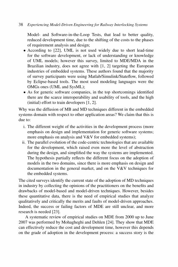
Model- and Software-in-the-Loop Tests, that lead to better quality,reduced development time, due to the shifting of the costs to the phasesof requirement analysis and design;
• According to [22], UML is not used widely due to short lead-timefor the software development, or lack of understanding or knowledgeof UML models; however this survey, limited to MDE/MDA in theBrazilian industry, does not agree with [1, 2] targeting the Europeanindustries of embedded systems. These authors found that the majorityof survey participants were using Matlab/Simulink/Stateflow, followedby Eclipse-based tools. The most used modeling languages were theOMGs ones (UML and SysML);
• As for generic software companies, in the top shortcomings identifiedthere are the scarce interoperability and usability of tools, and the high(initial) effort to train developers [1, 2].
Why was the diffusion of MB and MD techniques different in the embeddedsystems domain with respect to other application areas? We claim that this isdue to:
i. The different weight of the activities in the development process (moreemphasis on design and implementation for generic software systems;more emphasis on analysis and V&V for embedded systems);
ii. The parallel evolution of the code-centric technologies that are availablefor the development, which raised even more the level of abstractionduring the design, and simplified the way the systems are implemented.The hypothesis partially reflects the different focus on the adoption ofmodels in the two domains, since there is more emphasis on design anddocumentation in the general market, and on the V&V techniques forthe embedded systems.
The cited surveys identify the current state of the adoption of MD techniquesin industry by collecting the opinions of the practitioners on the benefits anddrawbacks of model-based and model-driven techniques. However, besidesthese quantitative data, there is the need of empirical studies that analyzequalitatively and critically the merits and faults of model-driven approaches.Indeed, the success or failing factors of MDE are still unclear, and moreresearch is needed [23].
A systematic review of empirical studies on MDE from 2000 up to June2007 was performed by Mohagheghi and Dehlen [24]. They show that MDEcan effectively reduce the cost and development time, however this dependson the grade of adoption in the development process: a success story is the

2.3 The Maturity of MDE 39
one of Motorola [25, 26], that used MDE for more than 15 years in a widespectrum of activities, ranging from protocol implementations up to handhelddevices or network controllers; they experienced an increase in quality andproductivity (ranging from 1.2× to 8×) and an approximately 33% reductionin the effort required to develop test cases.
Motorola could achieve these results within a mature process that wassupported by own-made translators and tools for the model exploitation.Indeed, one common issue of MDE is the absence of well-defined processes[24, 27, 28], as the application of MDE requires changes in the activities,corporate culture and skills of the employees: many software engineeringmethods are not fitted to use models as main artifacts, and the environmentsseems not mature enough. Some previous studies attempted to apply pre-existing processes to MDE, or to create own ones, but MDE shifts theimportance of many activities to (automatic) transformation rules, and changeconsolidated development process is not a naive task. The study [29] reports asuccessful introduction of a MBE process after 4 years and three projects hadbeen defined and consolidated: there is the need to look beyond the technicalbenefits of a particular approach to MDE and instead concentrate on socialand organizational issues [16].
Moreover, the process becomes a more difficult problem in safety-criticaldomain, where compliance with certification standards poses additionalrequirements on the methodologies for product life cycle. For these kind ofsystems, the major part of costs are for the activities of V&V, so rigorousand well-assessed techniques have to be integrated within the developmentprocess for the early detection of faults and to guarantee the quality of theproduct. In addition, non-functional requirements, such as safety, reliabi-lity and timing requirements, are a primary concern that have to be takeninto account by these processes: current MDE methodologies do not copewith stringent functional requirements and qualities in current systems, i.e.,the ability of these approaches to adapt to rapidly changing hardware andimplementation platforms that are highly complex [23].
Parallel to the challenge of the product life cycle, there is the open prob-lem of the supporting tools: they are not mature yet, and influence most of theadoption of MDE. Moreover, the vendor lock-in problem is also perceivedas a problem, and the companies prefer to adopt open source solutions orto develop their own tools. Indeed, the tools are not well usable, do notinteroperate between themselves, do not keep in synchronization the modelsat different level of abstractions, are not flexible to collaborative working,and are not suited with the adoption of different models and modeling

40 Experiencing Model-Driven Engineering for Railway Interlocking Systems
notations [23]. Thus, model-driven processes have to carefully consider theproblem of defining the toolchain for supporting the activities.
2.4 A Model-Driven Methodology for Prolan
In the period when CECRIS started, Prolan was developing the next gener-ation of railway interlocking systems, and in particular the first product ofthis generation, the Prolan Block (PB), a safety-critical system for railwayinterlocking that must be CENELEC EN 50126, EN 50128 and EN 50129SIL-4 certified.
The system is deployed alongside railway segments, which are namedblocks. Each block is equipped with a PB, with sensors for detecting incomingand outgoing trains (these sensors are the axle counters), and with semaphoresthat are part of the signaling system. The PB manages the block (Figure 2.1),receiving data from sensors, and properly setting the semaphores accordingto its internal state.
The interlocking is realized by the overall distributed system that consistsof interacting PBs, which must ensure that no collision will happen on therailway, directing the train movements by proper sequences of signals. Forinstance, according to the specific regulations, the yellow lamps can indicatethat the next block’s semaphore is red because there is an obstacle (e.g., atrain) in the block after the next (e.g., there is a train two semaphores ahead).
Figure 2.1 A representation of the Prolan Block and its operating environment.

2.4 A Model-Driven Methodology for Prolan 41
Prolan was interested in understanding the potentialities that model-driven technologies could give for the development of the PB and for theother products of the same generation. Indeed, small and medium size enter-prises like Prolan are interested in model-driven technologies but there arebarriers to their introduction, for the deep changes that these require into theorganization and in the current industrial practices. Indeed, for the adoptionof MDE Prolan needs to carefully rethink and redesign its current productdevelopment life cycle, that currently complies with the railway standardsCENELEC EN 50126, EN 50128 and EN 50129, as well as the skills of theemployees, even if no proven-in-use model-driven lifecycle for this domainis available and supported by long-term evidence.
The traditional Prolan development life cycle follows the V-Model andis compliant with the European railway standard EN 50128. The activitiesof the CENELEC V-Model process can be grouped in those concerningdevelopment, that are on the left side of the ‘V’, and those focusing onV&V, that are on the opposite side as it can be seen in Figure 2.2. Theactivities of V&V require planning stages that are performed before theiractual execution: these planning stages are carried out during design.
Besides the activities in the V-Model, CENELEC EN 50128 also pre-scribes requirements on the documents produced at each stage, as well ason the project organization. For instance, if we consider the highest integritylevel (SIL-4), distinct people have to test, verify and validate the product, inorder to cross-check their work. The phases adjacent to the ‘V’, the SoftwarePlanning and Software Assessment, aim at tuning and assessing the activitiesof the life cycle, defining the tasks to be performed during the process andchecking that the product and all artifacts satisfy the requirements and complywith the standard.
To gain experience on model-driven technologies, Prolan started a col-laboration with CINI in the framework of the CECRIS Project to develop adevelopment process enhanced with model-driven approaches.
Since Prolan wanted a concrete and feasible option for replacing itscurrent methodology, the researcher proposed a development process backedto Prolan’s traditional process. This solution minimizes the impact of thechange on the organization, and is also compatible with the safety standardspursued by the company. The adaptation of the development processes ofProlan to MDE focused on core phases of the CENELEC V-Model, startingfrom the System Development Phase up to the Software Validation Phase,i.e., on the Software Development Life Cycle (SDLC).
42 Experiencing Model-Driven Engineering for Railway Interlocking Systems
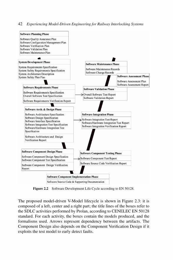
Figure 2.2 Software Development Life Cycle according to EN 50128.
The proposed model-driven V-Model lifecycle is shown in Figure 2.3: it iscomposed of a left, center and a right part; the title lines of the boxes refer tothe SDLC activities performed by Prolan, according to CENELEC EN 50128standard. For each activity, the boxes contain the models produced, and theformalisms used. Arrows represent dependency between the artifacts. TheComponent Design also depends on the Component Verification Design if itexploits the test model to early detect faults.

2.4 A Model-Driven Methodology for Prolan 43
Figure 2.3 The adapted model-driven V-Model life cycle for Prolan [31].
On the left there are forward engineering activities (system analysis,design and implementation); the phases in the center are for V&V planning,while on the right side there are the activities of V&V execution. TheCENELEC V-Model life cycle adopts implicitly different viewpoints on thesystem for each level of the ‘V’: the top level focuses on the system as awhole, the level below uses a viewpoint on the system architecture, then itconsiders the components and their internal design; finally, the lowest levelof the ‘V’ sees source code details. These abstractions are used on both sidesof the V-Model, for development and V&V.
The activities are assigned to a number of roles that comply withthe CENELEC EN 50128 standard. We consider the following roles andresponsibilities:
• The Requirements Manager is responsible for specifying the softwarerequirements. (S)he shall be competent in requirements engineering andbe experienced in application’s domain (as well as in safety attributes);
• The Designer transforms software requirements into a solution, definingthe system architecture and developing component specifications. (S)hehas be competent in the application area, and in safety design principles;
• The Implementer transforms design solutions into data, source code orother representations to create the product software artifacts. (S)he has tobe competent in engineering of the application area and implementationlanguages and supporting tools;
• The Tester develops the test specifications, and performs the test exe-cution. (S)he has to be competent in the domain where testing iscarried out;

44 Experiencing Model-Driven Engineering for Railway Interlocking Systems
• The Integrator manages the integration process using the softwarebaselines, developing the integration test specification. (S)he has to becompetent in the domain where component integration is carried out.
All these roles require advanced modeling skills, and experience with MDE,as well as with the adopted formalisms and tools.
The process starts with System Requirements Specification, by definingthe system environment and software requirements. Then, System Design andComponent Design are carried out. The former defines a high-level systemarchitecture, identifying the hardware-software interface, and the componentsinterfaces. Requirements are then allocated to components, and the Designerspecifies their responsibilities and expected interactions. Finally, in Compo-nent Design the Designer completes the components with the internal design,and the Implementation concludes the development.
For enabling forward engineering to model-driven technologies, wedefine in three stages a CIM, a PIM, and PSM, following the MDA principles.
The V&V planning activities (Validation Design, Integration VerificationDesign, and Component Verification Design) have been isolated at the centerof the V-Model. They are followed by the ones of V&V execution that areperformed on the right side of the ‘V’, i.e., Validation, Integration Verificationand Component Verification. For instance, Validation Design produces theOverall Software Test Specification after the System Requirement Specifi-cation. Then, the actual validation is performed in the Validation activity,at the end of the ‘V’, after Integration Verification, to assess the productconformance to requirements.
For the phases of V&V, we propose a model-driven methodology basedon the MDA abstractions: the planning phases use Platform Independent TestModels, whereas the execution phases build Platform-Specific Test Models.In fact, the V&V execution phases on the right side of the ‘V’ benefit fromthe availability of the implementation, which constrains the technologicalplatform.
Using this methodology, Prolan aims at improving the reuse of artifacts ofdesign and V&V, supporting most of activities of the life cycle with model-driven approaches. Prolan wanted to evaluate the adoption of OMG standards,i.e., SysML [30] and UML, to be open to multiple tools and promote theinteroperability of the models. It is worth to note that custom profiles can beintroduced in the process to potentiate the automatic generation of artifactsthroughout the whole SDLC, thus reducing the manual efforts.
We remark that since Prolan’s products must undergo safety certification,one of the main requirements of the methodology is to exploit model-driven

2.4 A Model-Driven Methodology for Prolan 45
technologies for supporting multiple activities of V&V. Indeed, the proposedprocess is open to multiple forms of V&V, and includes techniques of earlysystem validation, through the definition of the Computation IndependentTest (CIT) model.
2.4.1 Experimentation within A Pilot Project
Prolan started a pilot project on a subset of requirements for the ProlanBlock, in order to assess the benefits and drawbacks of the model-driventechnologies.
2.4.2 System Requirements Specification
At this phase, the Requirements Manager defines the system and the speci-fication of software requirements. We defined a CIM starting from the high-level system specification.
The CIM models requirements, and the relations between them, inSysML, because the language turns out particularly suited in this phase dueto the Requirement diagram, the Use Case Diagram, and the Block DefinitionDiagram. In particular, SysML Requirement Diagram is useful to displaytextual requirements, and their relationships, and to trace them with othermodeling elements.
Prolan built in the pilot project a CIM using MagicDraw [32], a modelingtool created by No Magic. Functional and non-functional requirements of thesystem were described using requirement diagrams meanwhile the systemcontext was described with block definition diagrams. Modeling using theMagicDraw tool was introduced in an earlier phase of the CECRIS projectin the framework of the knowledge transfer with Budapest University ofTechnology and Economics. Using models to capture requirements increasedrequirement quality significantly because the graphical representation madeit possible to overview complex systems as well as the constraints of the mod-eling environment forced the engineers to create consistent requirements. Wefound it convenient to separate functional and non-functional requirements indifferent groups as well as to mark derived requirements using the refinementrelationship.
An example of functional and non-functional requirements modeling canbe seen in Figures 2.4 and 2.5. As it can be seen from Figure 2.6, the PBsystem is connected to a Radio Block Center (RBC) to a PB Human MachineInterface (HMI) to a Station Interlocking System and to track occupancy

46 Experiencing Model-Driven Engineering for Railway Interlocking Systems
Figure 2.4 Prolan Block (PB) functional requirements.
Figure 2.5 PB non-functional requirements.
2.4 A Model-Driven Methodology for Prolan 47
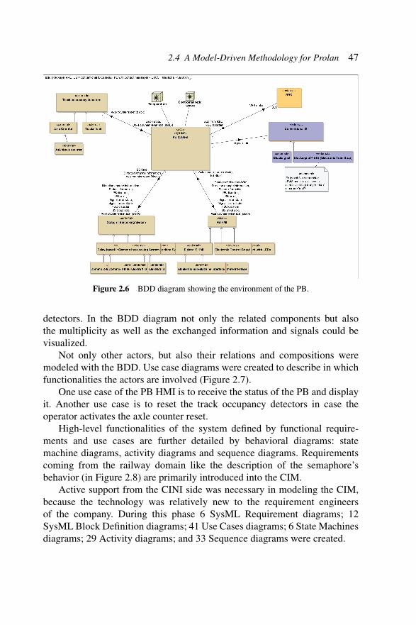
Figure 2.6 BDD diagram showing the environment of the PB.
detectors. In the BDD diagram not only the related components but alsothe multiplicity as well as the exchanged information and signals could bevisualized.
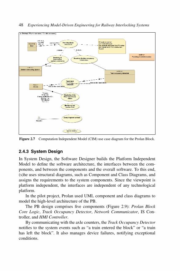
Not only other actors, but also their relations and compositions weremodeled with the BDD. Use case diagrams were created to describe in whichfunctionalities the actors are involved (Figure 2.7).
One use case of the PB HMI is to receive the status of the PB and displayit. Another use case is to reset the track occupancy detectors in case theoperator activates the axle counter reset.
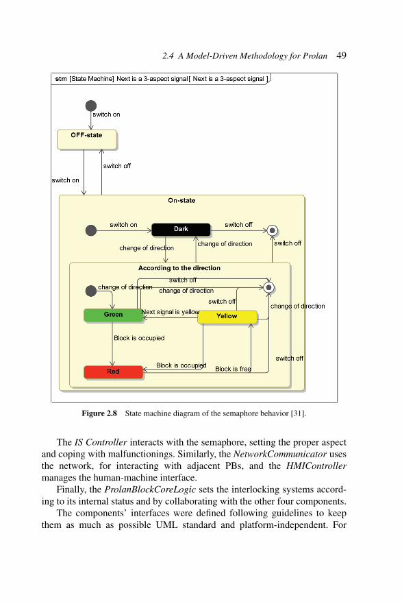
High-level functionalities of the system defined by functional require-ments and use cases are further detailed by behavioral diagrams: statemachine diagrams, activity diagrams and sequence diagrams. Requirementscoming from the railway domain like the description of the semaphore’sbehavior (in Figure 2.8) are primarily introduced into the CIM.
Active support from the CINI side was necessary in modeling the CIM,because the technology was relatively new to the requirement engineersof the company. During this phase 6 SysML Requirement diagrams; 12SysML Block Definition diagrams; 41 Use Cases diagrams; 6 State Machinesdiagrams; 29 Activity diagrams; and 33 Sequence diagrams were created.
48 Experiencing Model-Driven Engineering for Railway Interlocking Systems
Figure 2.7 Computation Independent Model (CIM) use case diagram for the Prolan Block.
2.4.3 System Design
In System Design, the Software Designer builds the Platform IndependentModel to define the software architecture, the interfaces between the com-ponents, and between the components and the overall software. To this end,(s)he uses structural diagrams, such as Component and Class Diagrams, andassigns the requirements to the system components. Since the viewpoint isplatform independent, the interfaces are independent of any technologicalplatform.
In the pilot project, Prolan used UML component and class diagrams tomodel the high-level architecture of the PB.
The PB design comprises five components (Figure 2.9): Prolan BlockCore Logic, Track Occupancy Detector, Network Communicator, IS Con-troller, and HMI Controller.
By communicating with the axle counters, the Track Occupancy Detectornotifies to the system events such as “a train entered the block” or “a trainhas left the block”. It also manages device failures, notifying exceptionalconditions.
2.4 A Model-Driven Methodology for Prolan 49
Figure 2.8 State machine diagram of the semaphore behavior [31].
The IS Controller interacts with the semaphore, setting the proper aspectand coping with malfunctionings. Similarly, the NetworkCommunicator usesthe network, for interacting with adjacent PBs, and the HMIControllermanages the human-machine interface.
Finally, the ProlanBlockCoreLogic sets the interlocking systems accord-ing to its internal status and by collaborating with the other four components.
The components’ interfaces were defined following guidelines to keepthem as much as possible UML standard and platform-independent. For

50 Experiencing Model-Driven Engineering for Railway Interlocking Systems
PBObjects
:ProlanBlockCoreLogic1
HMIControllerReq
IHMIControllerListener IHMIController
IConventionalISListener
IConventionalISController
ConvISReq
ITrackOccupanyListener
ITrackOccupancyDetector
TrackOccReq
INetworkManagerListener
INetworkManager
NetworkPortReq
IHMIControllerIHMIControllerListener
HMIControllerReq
ConvISReq
IConventionalISController
IConventionalISListener
ITrackOccupanyListener
ITrackOccupancyDetector
TrackOccReq
INetworkManager
NetworkPortReq
INetworkManagerListener
:TrackOccupancyDetector1ITrackOccupancyDetector
ITrackOccupanyListener
TrackOccPro
ITrackOccupancyDetector
TrackOccPro
ITrackOccupanyListener
:ISController1IConventionalISController
IConventionalISListener
ConvISPro
IConventionalISController
ConvISPro
IConventionalISListener
:NetworkCommunicat1
INetworkManager
INetworkManagerListener
NetworkPortPro
INetworkManager
INetworkManagerListener
NetworkPortPro
:HMIController1
IHMIController
IHMIControllerListener
HMIControllerPro
IHMIController
IHMIControllerListener
HMIControllerPro
Figure 2.9 High-level system architecture [31].
instance the services of any middleware or library have been defined interms of abstract interfaces, and the data types of the variables neglected onespecific programming language.
2.4.4 Component Design
The next phase is Component Design: here the Designer refines the PIM, tospecify the internal design of the components. (S)he identifies all lowest soft-ware units, fully detailing their input and output, and specifying algorithmsand data structure. The PIM becomes complete, and can be runnable andobject of simulation.
In the pilot project, Prolan defined the PIM using IBM Rhapsody Deve-loper [33] (hereinafter: Rhapsody), but following the guidelines to build amodel platform-independent. Indeed, the tool does not allow a clear separa-tion between a PIM and a PSM, thus we avoided to insert C++ code, andadopted UML compliant syntax where possible.

2.4 A Model-Driven Methodology for Prolan 51
Only few parts could not be specified in a platform-independent style.However, these parts were specified in C++, to exploit the model anima-tion feature of Rhapsody. Indeed, Prolan was interested in this feature as atechnique of early fault detection: Rhapsody’s model animation generates aninstrumented implementation of the model that allows to observe at runtimethe program execution. This feature was useful and valuable for getting animmediate feedback on the design.
By Rhapsody Panel Diagrams, we drew a graphical user interface boundto the model that enabled to generate and receive model events at runtime. Ofcourse, the execution can be also followed on behavioral diagrams, e.g., statemachines or sequence diagrams.
2.4.4.1 ImplementationImplementation phase deals with the production of software that is analy-zable, testable, verifiable and maintainable. Following MDA, the PIM isrefined into one (or more) Platform Specific Models that are bound to targetplatforms. The PSM adds low-level implementation details. For instance, aPSM binds data and interfaces to the target OS and middleware chosen forthe instantiation of the PIM.
Using IBM Rhapsody, Prolan set tagged values and other parameters toenrich the PIM with information platform-specific details, to specify how totranslate the association (e.g., by static or dynamic arrays), what is the clockfor the scheduler of the state machines’ event queues, and other parameters.These are used by Rhapsody for the automatic translation of PSM into code.
Considering the requirements of the PB, Prolan specified that the gen-erated code cannot use dynamic memory and that the variables have to beinitialized at runtime, due to the lack of memory isolation on Prosigma, thetechnological platform for the PB. The platform specific code can also exploitthe round-trip code feature of MDE tools:
1. By automatic code generation, packages, code skeletons, make files andother artifacts are automatically model-to-text produced;
2. The Implementer fills the code skeletons with platform-specific details,using the support of modern development environments (such asEclipse);
3. By code round-trip, the model is automatically augmented with theinformation written manually by the Implementer in the source code.
According to the requirements, there are many options for the translatorthat include the execution framework at runtime. For instance, Rhapsody
52 Experiencing Model-Driven Engineering for Railway Interlocking Systems
offers two C/C++ frameworks: IBM Rhapsody Object Execution Framework(OXF), and IBM Rhapsody Simple Execution Framework (SXF). The latter isdedicated to embedded systems and safety-related development: qualificationkits support the certification of the automatic generated code for severalstandard (including ISO 26262, EN 50128 and recently DO-178B).
The translation of our PSM in C++ source code generated around 7.5thousands of lines of code for a platform using a conventional OS, 7.3 thou-sands for target platform using a commercial Real Time Operating System(VxWorks), and 5.9 thousands C lines of code for an embedded systems notusing an OS. We used the SXF framework in the last code generation.
2.4.5 Validation Design
For Validation Design, we propose a model, named CIT Model, to specify thebehavior of the actors and of the environment. CIT can be used for designingvalidation tests, e.g., as UTP sequence diagrams representing the interactionsof the actors with the system.
Prolan decided to does not build a CIT model for the Prolan Block, andthe benefits of CIT modeling have been experimented on another system, theProlan Monitor, that is discussed in the next section.
2.4.6 Integration Verification Design
During Integration Verification Design, the Integrator realizes integrationtests to show that components behave correctly when integrated together. Theexpected behavior of the components is independent from their inner design,thus we refer to this model is named Black Box Platform Independent TestModel (BB-PIT).
BB-PIT provides static and dynamic views of the system’s compo-nents, and supports functional testing for unit/integration/system verification(Figure 2.10). The static description supports the generation of test harness,such as stubs and drivers for unit and integration testing. The dynamicdescription supports the generation of test suites and test cases.
The components’ behavior seems modeled twice, in PIM and BB-PIT.However, the two models have different purposes: the first specifies how tobuild the system, and represents the specification that an actual implementa-tion must comply with; the second describes the expected behavior in a wayto verify its correspondence between requirements and implementation (e.g.,by test cases).

2.4 A Model-Driven Methodology for Prolan 53
Figure 2.10 The transformations of the BB-PIT.
For tests specification, UML-UTP Sequence diagrams are less error-prone than textual notations, and it is easier to derive test cases for multipletarget platforms (such as TTCN-3 and JUnit), enhancing reusability andmaintainability.
In the pilot project, Prolan adopted Conformiq Designer (from hereonward: Conformiq) [34] to generate automatically test cases from theBB-PIT. However, since Conformiq is not fully compliant with UML, thebehavior was specified in QML, the language used by the tool. As ade-quacy criterion we used the requirement coverage, using the requirementtraceability offered by the model-driven tools.
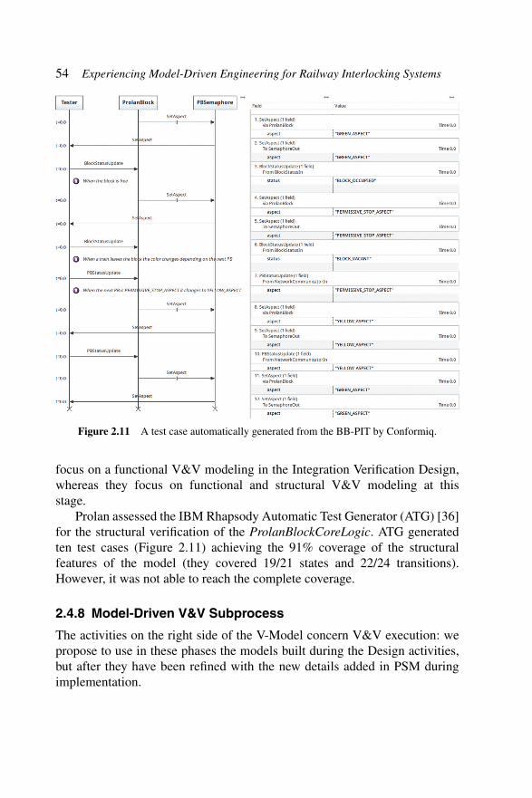
In total, Prolan achieved the full coverage of requirements generating 21test cases for the ProlanBlockCoreLogic. Test cases were exported to JUnitfrom sequence diagrams (Figure 2.11), and the tool also provided us withthe traceability matrix correlating test cases with the structural features theycover (states, transitions, requirements).
We also assessed the test harness generation from BB-PIT. Conformiqrequired to write the SUT adapter to let the testing framework interactwith the system. Instead, Rhapsody offers the Test Conductor Add On [35],that automatically generates the testing harness (including the drivers andstubs), starting from model design diagrams. Within Test Conductor we couldexecute test cases directly in Rhapsody, observing the effects, and followingthe behavior of the SUT by means of sequence diagrams.
2.4.7 Component Verification Design
In Component Verification Design tests have to confirm that componentsperform their intended functions. Here, we define the Grey Box Plat-form Independent Test (GB-PIT) Model, which is used for verificationby the internal view of the components. Following this flow, engineers
54 Experiencing Model-Driven Engineering for Railway Interlocking Systems
Figure 2.11 A test case automatically generated from the BB-PIT by Conformiq.
focus on a functional V&V modeling in the Integration Verification Design,whereas they focus on functional and structural V&V modeling at thisstage.
Prolan assessed the IBM Rhapsody Automatic Test Generator (ATG) [36]for the structural verification of the ProlanBlockCoreLogic. ATG generatedten test cases (Figure 2.11) achieving the 91% coverage of the structuralfeatures of the model (they covered 19/21 states and 22/24 transitions).However, it was not able to reach the complete coverage.
2.4.8 Model-Driven V&V Subprocess
The activities on the right side of the V-Model concern V&V execution: wepropose to use in these phases the models built during the Design activities,but after they have been refined with the new details added in PSM duringimplementation.
2.5 Environment System Validation 55
Thus, in Component Verification we named the model White Box Plat-form Specific Model (WB-PST), and the Tester adds new test cases consider-ing the details of the target platform. The WB-PST can be used to calculatethe test coverage on the basis of the final system code, as well as to supportany kind of verification of the actual code, such as to derive consistent andefficient code review plans by considering the component software metricsand implementation details.
Similarly, during Integration Verification phase the BB-PIT model isrefined in the Black Box Platform Specific Test Model (BB-PST), where plat-form specific details complete the integration test specification. For instance,the BB-PST can be exploited to perform interface testing, a technique that ishighly recommended by CENELEC EN 50128: interface testing is executedknowing the actual domain of all interface variables, and selecting particularinput to assess the behavior of the (integrated) components (e.g., at theirnormal, boundary, or invalid values).
Finally, in Validation phase, the Tester assesses that system and softwarerequirements are met. To this end, (s)he executes the overall system testsdefined in the CIT. Moreover, if the CIT is executable, the Tester can putthe CIT and the software in-a-loop, to perform software-in-the-loop andhardware-in-the-loop testing.
2.5 Environment System Validation
Our methodology also exploits MDE for validation, by defining an environ-mental model during Validation Design to analyze the actors’ behavior. Thismodel, named CIT Model, specifies the expected behavior of the environmentwhen interacting with the system by behavioral diagrams (e.g., Sequence,State Machine or Activity diagrams) that are used to derive validationtest case.
The CIT also appears in other studies [37] but our definition differsfrom the previous ones, since we define the CIT a model for validationthat abstracts from the computation details of the system under analysis(SUT), and also propose to develop the CIT as an executable model of theenvironment, with interfaces specular to those of the PIM. This definitionsupports multiple forms of V&V during the product life cycle.
Since the CIT has an interface specular to the one of the PIM, we can putthe two models in-a-loop and the CIT can be used to perform model-in-the-loop test (since it is runnable), enabling to:

56 Experiencing Model-Driven Engineering for Railway Interlocking Systems
• Validate the system against its expected interactions with external actors;• Create a simulated environment to reason about the operational aspects
of the system in its environment (also through model animation).
Model-in-the-loop (MIL) testing can be performed as soon as the PIM isavailable, i.e., during the Component Design, enabling to an early fault detec-tion. Moreover, if the Tester can use additional/external sources of knowledgeto model the actors’ behavior (such as domain knowledge or historical data),MIL testing can also be useful to detect missed software requirements, byassessing the behavior in a simulated environment.
Then, when a system implementation is available, the Tester can build anadapter to allow the CIT to interact with the actual SUT, allowing Software-and Hardware-in-the-loop Testing.
CIT also enables to performance testing, generally adopted for the assess-ment of critical systems, as it is recommended by the safety standards. Indeed,the CIT can generate inputs representative of the operational profile.
Other forms of verification allowed by the CIT are:Model-checking through the in-the-loop model. This can assess the
absence of undesired conditions during the operation, analyzing the statesof the PIM and CIT.
Back-to-back testing, a special case is when the CIT can be seen asanother PIM, for instance when we consider systems that act as client andserver at the same time. For this kind of systems, we can instantiate two PIMs,putting in-a-loop each other, to perform back-to-back testing.
2.6 Experimenting the CIT
The benefits of the CIT and of environmental modeling have been assessedin another part of the interlocking system with which Prolan Block interacts,the Prolan Monitor.
The Prolan Monitor (PM) shares with the PB the Prosigma hardware andmiddleware platform, which is the basis of the next generation of Prolan’sproducts.
The purpose of the PM is to send signals generated by legacy inter-locking devices to modern interlocking systems that communicate throughprotocols based on IP networks (such as via X.25 over TCP/IP). Morespecifically, PM monitors railway objects: each object is associated to onebit of information, which is encoded by one couple of valent and antivalentphysical signal values. The PM transmits the bit of information to otherdevices, detecting invalid values for the couple of electric signals. Indeed,

2.6 Experimenting the CIT 57
the input can suffer of special unstable states during which the signalsquickly alternate in their value for a transient time, called bounce time: thePM must properly filter the signals, separating transient noise from invalidinputs.
To assess the benefits of the CIT, Prolan made an executable model of thePM’s environment. The CIT is composed of two CIT Railway Objects: eachCIT Railway Object controls the couple of logical signals associated with thebinary information that they encapsulate; from the CIT point of view, the PMis an actor.
The CIT Railway Objects are implemented by a Signal Generator andan Event Generator: the Event Generator determines the next output tobe triggered (including transient and invalid states), as specified by a user-defined operational profile, whereas the Signal Generator sets the couple ofoutput signals and manages the duration of the transients.
A panel diagram makes the CIT interactive: a couple of knobs allow to setthe event generation period and to customize the duration of transient states.
Linking together with an adapter simulating a physical relay the CIT andthe PIM, we preliminarily performed Model-in-the-loop testing. Only chang-ing the adapter with a real hardware card forwarding the events to the actualSUT, we could also perform Hardware in-the-loop testing (Figure 2.12).
Figure 2.12 The configuration of the PM for HIL Testing.
58 Experiencing Model-Driven Engineering for Railway Interlocking Systems
2.7 Lesson Learned
The CECRIS knowledge transfer activities allowed assessing the maturityof MDE for railway interlocking systems. The project managers becameacquainted with MDE methodologies and tools, and Prolan started to considertheir introduction into the development processes.
Indeed, the pilot project showed that MDE is a mature technology, whichsupports the whole development process. Using SysML for requirementsspecification helped to produce better artifacts, reasoning formally on incon-gruences and missing specifications than with the current document-centricapproach. Also, fast prototyping, early fault detection, automatic test gener-ation, and other MDE features revealed a gain of productivity and qualityduring design and V&V phases than current methodology.
However, even for SME companies as Prolan that have limited engi-neering capacity, it is not easy to change current development process andpractices. MDE requires for a technological and knowledge transfer. Whilethe former can be addressed with personnel trainings, the latter is more subtle,long, and expensive. Therefore, Prolan submitted a joint tender proposaltogether with the Hungarian University, partner of CECRIS project, aimingat getting active support in their introduction during the next safety criticalproject, and to investigate model-driven technologies further.
Indeed, still an extensive experimentation of model-driven methodologiesis needed. By the pilot project on the Prolan Block we qualitatively assessedMDE: even if the benefits of model-driven approaches turned out to beevident, we could not easily evaluate how much time is needed for Prolan tohave a return of investment. This tender would introduce the academic know-how and support in the planning, design and implementation for a completeRailway Interlocking System project.
However, the current experience has been saved by Prolan, and if thetender is rejected then the enhancement of the current development lifecycleof Prolan with the one proposed in the framework of the pilot project will beapplied. The innovation is planned to be applied gradually, through severalstages expected to last several years.
At the first stage, Prolan targets to introduce models for supporting thecurrent activities, starting to use MBE than MDE approaches. For instance,it is expected to adopt modelling tools for system requirement specificationand system design phases. The current document-based system requirementsspecification and the the requirement management system will be replacedwith software using SysML models, taking benefits of the improved modeltraceability.
References 59
These first changes already raise knowledge and technologies issues: westill have not decided if to adopt exclusively SysML for describing the systemrequirements, because we could be not able to teach satisfactorily modelingand SysML to all the team members; moreover, we have not completed thetool selection process. Among the selection criteria it is required that newtools be stable, and easily interoperable with the other software suites alreadyin use at Prolan. The fully compliance with standards, and the vendor lock-inproblem are also of interest for the tool selection. The relatively high priceof licenses and the difficulty of using these modeling tools have an adverseeffect on the introduction of model-driven methodologies.
The CECRIS experience revealed that model-driven technologies canreally improve the development, enhancing quality of the product and ofthe development life cycle. Despite these advantages, the management ofthe railway product development decided to pursue a conservative approachtowards the introduction of model based tools and development methods: thebig issues of MDE concern skills and organization. The learning curve ofthese technologies is long and difficult to quantify, and the relevance of rolesduring the development will change, deeply impacting human-organizationalfactors. The innovation must be introduced gradually, taking into accountthese factors.
The benefits of cooperating with academic partners within the CECRISproject were manifold, as it was demonstrated by the pilot project: theexperience in the methodologies and tools enabled Prolan to receive activetutoring and support for the full product lifecycle, shortening the learningcurves and reducing the number of errors caused by the lack of knowledge,method, and experience with the tools. Moreover, the broad knowledge ofthe emerging new technologies in the field enabled the academic partners tosuggest the criteria in selecting the appropriate tools and methodologies.
References
[1] Liebel, G., Marko, N., Tichy, M., Leitner, A., and Hansson J. (2014).“Assessing the State-of-Practice of Model-Based Engineering in theEmbedded Systems Domain,” in Proceedings of the 7th InternationalConference on Model-Driven Engineering Languages and Systems(MODELS), eds. J. Dingel, W. Schulte, I. Ramos, S. Abrahao, and E.Insfran (Berlin: Springer International Publishing), 166–182.
[2] Marko, N., Liebel, G., Sauter, D., Lodwich, A., Tichy, M., Leitner, A.,and Hansson J. (2014). Model-based engineering for embedded systems

60 Experiencing Model-Driven Engineering for Railway Interlocking Systems
in practice. Research Reports in Software Engineering and Management,Technical report, University of Gothenburg, Gothenburg.
[3] Broy, M., Kirstan, S., Krcmar, H., Schatz, B., and Zimmermann, J.(2013). “What is the benefit of a model-based design of embedded soft-ware systems in the car industry” in Emerging Technologies for the Evo-lution and Maintenance of Software Models (Hershey, PA: IGI Global),343–369.
[4] CECRIS. (2016). EU Project CECRIS, CErtification of CRIticalSystems. Available at: http://www.cecris-project.eu
[5] Schmidt, D. C. (2006). “Guest Editor’s Introduction: Model-DrivenEngineering,” in: Computer 39.2, 25–31. Lecture Notes in ComputerScience (Berlin: Springer).
[6] Brambilla, M., Cabot, J., and Wimmer, M. (2012). Model-Driven Soft-ware Engineering in Practice. San Rafael, CA: Morgan & ClaypoolPublishers.
[7] Object Management Group (OMG). (2014). MDA Guide (Version 2.0).Available at: http://www.omg.org/cgi-bin/doc?ormsc/14-06-01 (accessedon 2016-03).
[8] Baker, P., Dai, Z. R., Grabowski, J., Haugen, Ø., Schieferdecker, I.,and Williams, C. (2007). Model-Driven Testing: Using the UML TestingProfile (New York, NY: Springer-Verlag New York, Inc.).
[9] Dai, Z. R. (2004). “Model-driven testing with UML 2.0,” in Proceedingsof the 2nd European Workshop on Model Driven Architecture (MDA)with an emphasis on Methodologies and Transformations (EWMDA),eds D. Akehurst, 179–187. Tech. rep. 17-04, University of Kent,Canterbury.
[10] Kent, S. (2002). “Model Driven Engineering,” in the Proceedings of theThird International Conference on Integrated Formal Methods (IFM),286–298. Berlin: Springer-Verlag.
[11] Object Management Group (OMG). (2003). MDA Guide (Version 1.0.1).Available at: http://www.omg.org/cgi-bin/doc?omg/03-06-01 (accessedon 2016-03).
[12] Davies, I., Green, P., Rosemann, M., Indulska, M., and Gallo, S. (2006).How do practitioners use conceptual modeling in practice? Data Knowl.Eng. 58.3, 358–380.
[13] Forward, A. and Lethbridge, T. C. (2008). “Problems and Opportunitiesfor Model-centric Versus Code-centric Software Development: A Sur-vey of Software Professionals,” in Proc. of the International Workshopon Models in Software Engineering (MISE) (New York, NY: ACM),27–32.

References 61
[14] Hutchinson, J., Rouncefield, M., and Whittle, J. (2011). “Model-drivenengineering practices in industry,” in Proceedings of the 33rd Interna-tional Conference on Software Engineering (ICSE) (New York, NY:IEEE), 633–642.
[15] Hutchinson, J., Whittle, J., Rouncefield, M., and Kristoffersen, S.(2011). “Empirical Assessment of MDE in Industry,” in Proceedingsof the 33rd International Conference on Software Engineering (ICSE)(New York, NY: ACM), 471–480.
[16] Hutchinson, J., Whittle, J., and Rouncefield, M. (2014). “Model-drivenengineering practices in industry: social, organizational and manage-rial factors that lead to success or failure,” in Science of ComputerProgramming 89, Part B (Amsterdam: Elsevier), 144–161.
[17] Whittle, J., Hutchinson, J., and Rouncefield, M. (2014). “The state ofpractice in model-driven engineering,” in IEEE Software 31.3 (NewYork, NY: IEEE), 79–85.
[18] Tomassetti, F., Torchiano, M., Tiso, A., Ricca, F., and Reggio, G. (2012).“Maturity of software modelling and model driven engineering: A sur-vey in the Italian industry,” in Proceedings of the 16th InternationalConference on Evaluation Assessment in Software Engineering (EASE)(New York, NY: ACM), pp. 91–100.
[19] Torchiano, M., Tomassetti, F., Ricca, F., Tiso, A., and Reggio, G. (2011).“Preliminary Findings from a Survey on the MD State of the Practice,”in Proceedings of the International Symposium on Empirical Soft-ware Engineering and Measurement (ESEM) (New York, NY: ACM),372–375.
[20] Torchiano, M., Tomassetti, F., Ricca, F., Tiso, A., and Reggio, G.(2012). “Benefits from modelling and MDD adoption: expectations andachievements,” in Proceedings of the 2nd International Workshop onExperiences and Empirical Studies in Software Modelling (EESSMod)(New York, NY: ACM), 1–6.
[21] Torchiano, M., Tomassetti, F., Ricca, F., Tiso, A., and Reggio, G. (2013).Relevance, benefits, and problems of software modelling and modeldriven techniques – A survey in the Italian industry. J. Syst. Softw. 86.8,2110–2126.
[22] Agner, L. T. W., Soares, I. W., Stadzisz, P. C., and Simo, J. M. (2013).A Brazilian survey on UML and model-driven practices for embeddedsoftware development. J. Syst. Softw. 86.4, 997–1005.
[23] Mussbacher, G., Amyot, D., Breu, R., Bruel, J. M., Cheng, B. H.C., Collet, P., Combemale, B., France, R. B., Heldal, R., Hill, J.,

62 Experiencing Model-Driven Engineering for Railway Interlocking Systems
Kienzle, J., Schottle, M., Steimann, F., Stikkolorum, D., and Whittle, J.(2014). “The relevance of model-driven engineering thirty years fromnow,” in Proceedings of the 17th International Conference on Model-Driven Engineering Languages and Systems (MODELS) eds. J. Dingel,W. Schulte, I. Ramos, S. Abrahao, and E. Insfran (New York, NY:Springer International Publishing), 183–200.
[24] Mohagheghi, P. and Dehlen, V. (2008). “Where Is the Proof? A Reviewof Experiences from Applying MDE in Industry,” in Proceedings of4th European Conference on the Model Driven Architecture – Founda-tions and Applications (ECMDA-FA), Vol. 5095, ed. I. Schiefer-deckerand A. Hartman. Lecture Notes in Computer Science. Springer BerlinHeidelberg, 2008, pp. 432–443.
[25] Baker, P., Loh, S., and Weil, F. (2005). “Model-Driven Engineering ina Large Industrial Context – Motorola Case Study,” in Proceedings ofthe 8th International Conference on Model Driven Engineering Lan-guages and Systems (MODELS), eds. L. Briand and C. Williams (Berlin:Springer), 476–491.
[26] Weigert, T. and Weil, F. (2006). “Practical experiences in using model-driven engineering to develop trustworthy computing systems,” in Proc.of the IEEE International Conference on Sensor Networks, Ubiquitous,and Trustworthy Computing, Vol. 1 (New York: IEEE), 208–215.
[27] Huhn, M. and Hungar, H. (2010). “8 UML for software safety andcertification,” in Model-Based Engineering of Embedded Real-Time Sys-tems: International Dagstuhl Workshop. Revised Selected Papers, eds.H. Giese, G. Karsai, E. Lee, B. Rumpe, and B. Schatz (Berlin: Springer),201–237.
[28] Pettit, R., Mezcciani, N., and Fant, J. (2014). “On the needs andchallenges of model-based engineering for spaceflight software sys-tems,” in Proceedings of the IEEE 17th International Symposium onObject/Component/Service-Oriented Real-Time Distributed Computing(ISORC) (New York: IEEE), 25–31.
[29] Ferrari, A., Fantechi, A., and Gnesi, S. (2012). “Lessons learnt fromthe adoption of formal model-based development,” in Proc. of 4th Inter-national Symposium on the NASA Formal Methods (NFM), eds. A. E.Goodloe and S. Person (Berlin: Springer), 24–38.
[30] Object Management Group (OMG). (2008). Systems modeling language(SysML). Available at: http://www.omg.org/docs/formal/08-11-02.pdf(accessed on 2016-03).

References 63
[31] Scippacercola, F., Pietrantuono, R., Russo, S., Zentai, A. (2015).“Model-driven engineering of a railway interlocking system,” in Pro-ceedings of the 3rd International Conference on Model-Driven Engi-neering and Software Development (MODELSWARD 2015) (Setubal:SCITEPRESS), 509–519.
[32] No Magic, Inc. (2016). Magic Draw. MagicDraw. Available at: http://www.nomagic.com/products/magic-draw.html (accessed on 2016-03).
[33] IBM Corp. (2016). Rationalr Rhapsodyr Developer. Availableat: http://www-03.ibm.com/software/products/it/ratirhap (accessed on2016-03).
[34] Conformiq Inc. Conformiq Designer. http://www.conformiq.com/products/conformiq-designer, (accessed on 2016-03).
[35] IBM Corp. (2016). Rationalr Rhapsodyr Test Conductor Add On. UserGuide. Available at: http://pic.dhe.ibm.com/infocenter/rhaphlp/v7r6/topic/com.ibm.rhp.oem.pdf.doc/pdf/RTCUserGuide.pdf (accessed on2016-03).
[36] IBM Corp. (2016). Rationalr Rhapsodyr Automatic Test GeneratorAdd On. User Guide. Available at: http://pic.dhe.ibm.com/infocenter/rhaphlp/v7r5/topic/com.ibm.rhapsody.oem.pdf.doc/pdf/ATG-UserGuide.pdf (accessed on 2016-03).
[37] Schieferdecker, I. (2005). “The UML 2.0 Test Profile as a Basis forIntegrated System and Test Development,” in Proceedings of KollenDruck+Verlag GmbH, Jahrestagung der Gesellschaft fur Informatik(Germany: Kollen Druck & Verlag GmbH), Vol. 35, pp. 395–399.
