experiences from the commissioning and first physics run
TRANSCRIPT

October 10, 2018
Experiences from the Commissioning and First Physics Run ofthe Fermilab Muon g-2 Experiment
Ran Hongon behalf of the Muon g-2 Collaboration
Argonne National Laboratory, High Energy Physics Division9700 S Cass Ave, IL 60439, USA
The Muon g-2 Experiment (E989) at Fermilab is seeking to measurethe anomalous magnetic moment of muon (aµ) with a precision of 140parts-per-billion (ppb) and aiming to resolve the discrepancy between theE821 measurement and the Standard Model calculation of aµ. In E989,the muon beam is stored in a ring magnet. The anomalous spin precessionfrequency ωa is measured by counting decay positrons in 24 calorimeters,and the magnetic field is measured by nuclear magnetic resonance (NMR)probes. Improvements in this experiment with respect to its predecessorand the progress achieved in the commissioning run and the first physicsrun, Run-1, are presented.
PRESENTED AT
Thirteenth Conference on the Intersections of Particle andNuclear Physics
Palm Springs, CA, USA, May 29 – June 3, 2018
arX
iv:1
810.
0372
9v1
[phy
sics
.ins-
det]
8 O
ct 2
018
FERMILAB-CONF-18-551-E
This document was prepared by Muon g-2 collaboration using the resources of the Fermi National Accelerator Laboratory (Fermilab), a U.S. Department of Energy, Office of Science, HEP User Facility. Fermilab is managed by Fermi Research Alliance, LLC (FRA), acting under Contract No. DE-AC02-07CH11359.

1 Introduction
The g-factor of a particle is the ratio of its magnetic moment (measured in µB ≡q/2m) and spin, and for spin-1/2 elementary particles g = 2 if no quantum correctionsare taken into account. Due to quantum corrections, the g-factor deviates from 2 [1],and the lepton magnetic anomaly a = (g−2)/2 describes the amount of the deviation.The part-per-billion level agreement between the measured electron anomaly ae andthe prediction of it based on the Standard-Model (SM) physics has been a benchmarkfor the validity of quantum electrodynamics (QED) [2]. For muons, aµ was measured(in experiment E821) with a precision of 540 ppb at Brookhaven National Lab [3]. In2006, the final result of E821 was different from the SM prediction by 2.5 standard de-viations. This difference motivated the physics community to search for mechanismsbeyond the SM [4] that can explain the difference, as well as more accurate calcula-tions of the contributions to aµ from the known physics within the SM [5]. Recentlythere have been great progresses in calculating the contributions from hadronic vac-uum polarization (HVP) diagrams and hadronic light-by-light (HLbL) diagrams. Theuncertainty on the HVP contribution was improved by using the dispersion-relationapproach [6] with more recent experimental data [7], while the HLbL contribution wasbetter estimated using Lattice-QCD [8]. Recently Lattice-QCD calculations for HVPand dispersion-relation approach for HLbL are also developed [9, 10, 11]. Recent re-sults [5] are shown in Figure 1, and the difference between the theoretical calculationsand the previous measured value persists.
Figure 1: Recent theoretical calculations of the anomalous magnetic moment of muonaµ in the Standard Model. The result of the experiment E821 and the projected un-certainty of E989 are also shown. This figure was originally presented in Reference [5].
1

The Muon g-2 Experiment at Fermilab (E989) [12] is aiming at reducing theexperimental uncertainty down to 140 ppb, a factor of 4 improvement from E821.The new result will help resolve the aSMµ − aEXP
µ discrepancy with higher confidence.To achieve this goal, E989 will record 21 times the E821 data set, while varioussources of systematic uncertainties will be reduced by improved instrumentation. Inthis paper, an overview of the aµ measurement principles are presented in Section 2.The E989 experiment design and commissioning progress are described in Section 3.The current progress in Run-1 is described in Section 4.
2 Measurement principles
In E989, a polarized muon beam is injected into a storage ring with a uniform mag-netic field. Because g 6= 2 the spin precession angular velocity ~ωs is different from thecyclotron angular velocity ~ωc. Assuming that the magnetic field is perfectly uniformand betatron oscillations of the beam are neglected, the difference of ~ωs and ~ωc is [3]:
~ωa = ~ωs − ~ωc = − e
mµ
[aµ ~B −
(aµ −
1
γ2 − 1
) ~β × ~E
c
], (1)
where ~B and ~E are the magnetic and electric fields in the storage ring, ~β = ~v/c isthe velocity of the muon relative to the speed of light, and γ = 1/
√1− β2. In the
muon storage ring a static electric field is used to focus the muon beam vertically.In order to reduce the magnitude of the ~β × ~E term in Eq. 1, the momentum of themuon beam is chosen to be 3.094 GeV/c (γ = 29.3) so that the coefficient of this termvanishes. In this experiment the anomalous precession angular frequency ωa and theaverage magnetic field strength B̃ experienced by the muons are measured separately,and the anomalous magnetic moment is proportional to the ratio of them:
aµ = −mµωa
eB̃. (2)
ωa is extracted from the rate of positrons emitted in the muon decay µ+ → e+νeνµ.Due to parity violation in weak interactions, the angular distribution of the emittedpositrons is not isotropic. In the rest frame of a positive muon, high-energy positronsare more likely to be emitted along the muon spin. As the spin of the muon precesses inthe magnetic field, the asymmetric angular distribution of the positrons also rotatesat the angular frequency ωa. Because the kinetic energy of the muons in the labframe is much higher than the rest-frame end-point energy of the emitted positrons,the positrons experience a huge Lorentz boost. Therefore, most of the positrons areemitted in the forward direction, and their lab-frame energies Elab strongly dependon their emission angle θ∗ in the rest frame relative to the boost direction
Elab ≈ γE∗(1 + cos θ∗) (3)
2

where E∗ is the positron energy in the rest frame of the muon. Through this mech-anism, Elab also oscillates at the angular frequency ωa. The emitted positrons haveless momenta than the muons, so their orbit radius in the magnet is smaller thanthe muon storage orbit radius and they curve towards the inner side of the ring andeventually hit the calorimeters that measure the arrival time and energy depositionof the incoming particles. From the calorimeter readings, one can reconstruct the en-ergy deposition versus time and extract its oscillation angular frequency (Q-method),or set a threshold on energy and reconstruct the positron count versus time and ex-tract its oscillation angular frequency (T-method). These two methods have differentsystematic uncertainties, and in E989 both of them are implemented by different anal-ysis teams, and their results will be compared and evaluated before the final result isreleased.
The magnetic field in the muon storage region is mapped using proton nuclearmagnetic resonance (NMR) probes. The NMR system determines the free-protonprecession angular frequency ωp which is proportional to the magnitude of the mag-netic field. The average magnetic field ω̃p experienced by the muons is obtained byintegrating the ωp map weighted by the measured muon distribution map. To expressaµ in terms of ωa and ω̃p, Eq. 2 becomes
aµ =ge2
mµ
me
µpµe
ωaω̃p, (4)
where ge is the g-factor of an electron, mµ/me is the muon-to-electron mass ratio,and µp/µe is the proton-to-electron magnetic moment ratio, and these three valuesare already measured with uncertainties better than 22 ppb in experiments [2, 13, 14].
3 Overview of the E989 commissioning progress
The construction of E989 started in 2013, and in May 2017 most of the major com-ponents were built and installed. After 11 months of studying and improving theexperiment, E989 was commissioned and Run-1 started at the end of March 2018. Inthis section, key components of the experiment will be described, together with theimprovements compared to E821 and the milestones achieved during the commission-ing period.
3.1 Muon beam line
The muon beam [15] used in E989 is produced by the Fermilab accelerator complex.Hydrogen ions generated at the Ion Source are accelerated to 400 MeV in the LinearAccelerator and then boosted to 8 GeV in the Booster. The proton beam from theBooster is then directed to the Recycler for bunching, and then impinged on a Inconel
3

target to create pions. Positive pions with 3.11 GeV/c momentum are selected anddirected into the Delivery Ring which was used as a part of the anti-proton sourcewhen the Tevatron was in use. Polarized muons with 3.094 GeV/c momentum arecaptured from forward-going pion decays. In the delivery ring, the beam goes forseveral turns while more pions decay into muons, and the muon bunch is separatedspatially from the remaining protons so that a clean muon bunch can be extracted.The extracted muon bunches are delivered to the muon storage ring in the Muong-2 Experiment Hall. In May 2017, all the beamlines except the Delivery Ring werecommissioned. The latter was commissioned in December 2017. In the early runsfrom May to December 2017 protons and pions were injected together with muonsinto the storage ring, and since December 2017 protons and pions were eliminatedbefore injection. Through the commissioning run, the muon beam was tuned andimproved to optimize the number of muons delivered to the experiment. In May2018, 300,000 muons per bunch were being recorded just prior to injection throughthe storage ring yoke, which is close to the goal set in the Technical Design Report[12].
3.2 Muon storage ring
The superconducting ring magnet provides a 1.45 T uniform magnetic field to storethe muons. It is the same magnet [16] used in E821, and it was transported toFermilab in the summer of 2013. The superconducting coils with their cryostatswere transported as a whole, while the iron pieces were disassembled and transportedseparately and then reassembled. The magnet was successfully cooled and poweredin 2015, and since then procedures for operating the magnet safely and stably weredeveloped.
Figure 2: The photo of the storage ring magnet and its cross-sectional view. Thecircular region between the poles represents the muon storage region. The magicradius of ρ=7112 mm relative to the center of the ring is labeled. The superconductingcoils are marked by the rectangles at the inner and outer radii.
4

The cross-section of the storage ring magnet is shown in Figure 2. The magneticfield points vertically upwards in the space between the pole pieces. To achieve abetter uncertainty on ω̃p, the magnet has to be shimmed to a higher uniformity thanthat was the case in E821. In the magnet shimming campaign of E989, each of theadjustable iron pieces (top/bottom hats, pole pieces, edge shim and wedge shims)was adjusted carefully to reduce the transverse (radial and vertical directions) andlongitudinal (azimuthal direction in the ring) gradients of the field. To shim the non-uniformity at even shorter scales than the sizes of these iron pieces, customized ironfoils were used to increase the field strength where the field was weak. ∼8500 preciselycut iron foils were epoxied to the surface of the pole pieces. It took 10 months tofinish the shimming, and the peak-to-peak variation of the field reached ±25 ppm inthe azimuthal direction and ±4 ppm in the transverse directions [17]. Besides thesepassive shimming techniques, 200 concentric coils are placed on the surface of the polepieces, and the current in the coils are programmable in order to cancel the remainingtransverse field non-uniformity. After optimizing the current in the coils, the peak-to-peak variation of the azimuthally averaged field cross-sectional map was reducedto 2.5 ppm. The current in the main magnet coils can be actively adjusted based onthe field measurements by the fixed probes. This feedback mechanism maintains thefield at a constant value over a long time period.
Twelve sections of the storage ring vacuum chamber inherited from E821 werecleaned and installed by March 2017. Some chambers were modified to host newdevices like the in-vacuum straw trackers. Inside the vacuum chamber all aroundthe ring, there are rails guiding the magnetic field scanning device. Because the railsdetermine the radial and vertical coordinates of the field scanner, the positions andshapes of rails in each chamber section were aligned at the sub-millimeter level.
The muon beam enters the magnet through an aperture in the back of the ironyoke. From the inner edge of the iron yoke to the edge of the pole pieces, he magneticfield increases from near zero to the full field strength. To prevent the beam frombeing deflected by the main field before reaching the storage region, a superconductingmagnet called the inflector is used to cancel the main magnetic field along the path ofthe muon beam between the cryostat of the outer magnet coils and the storage ringvacuum. It has a superconducting shield so that the field generated by the inflectorcurrents does not affect the highly uniform field in the beam storage region. Theinflector used in E821 was installed and has been operated since December 2016. Anew inflector magnet with an open-ended design is being built for FY20 running. Theopen-ended inflector does not scatter muons at the exit and so will improve the muonstorage efficiency.
When the muons exit the inflector they are displaced radially 77 mm outward fromthe central (ideal) orbit of the storage ring, and therefore after injection the muonorbit is a circle offset by the same amount from the ideal orbit. The muons cross theideal orbit approximately 90◦ azimuthally downstream from the end of the inflector.
5

Figure 3: Schematics of the muon beam entering the storage ring through the tunnelin the iron and then the inflector.
At this point, the direction of the muons are not tangential to the ideal orbit. Thekicker magnet imposes a fast magnetic field pulse to the incoming muon bunch, andbends them onto the ideal orbit. There are three kickers in the E989 storage ring,and each of them is a pair of metal plates on the inner and outer radius of the beam.A ∼5000 A current is conducted through the plates creating a transient vertical fieldpeaked at ∼250 Gauss. The ideal pulse shape of the kicker is square with a flat topthat lasts for ∼100 ns. This ideal pulse was not achieved during the commissioningrun and significant work was undertaken to improve the characteristics of the pulseand a larger kicker pulse will be available in the upcoming FY19 run.
Electrostatic quadrupoles are used in the storage ring to confine the muon beamvertically, and they cover ∼43% of the total circumference. The electrodes from E821were polished, aligned and installed into the vacuum chambers early in 2017. Theelectrodes are aluminum plates. When the muon beam moves from the inflector to thekicker for the first time, it passes through the outer electrode. In E989 this electrodeis made of aluminized mylar in order to reduce the beam scattering and thus improvethe beam storage efficiency. Because of the variance in the muon momentum, notall muons are at the magic momentum and a small correction must be applied toωa. The positions of the electrodes are surveyed to the sub-millimeter level and theelectric field generated by the electrodes are modeled by Opera3D. The electrodes aredesigned to be operated up to 25 kV. Dedicated procedures have been developed tocondition the electrodes and to date data has been taken with potentials between 15and 21 kV.
6

3.3 Detector system
Twenty-four calorimeter stations are evenly distributed along the storage ring on theinner side of the vacuum chamber. Decay positrons exit the vacuum chamber throughits aluminum wall and immediately enter the PbF2 crystals of the calorimeters. Thehigh-energy positron generates a shower of Cherenkov light in the crystal, and thenumber of photons are proportional to the energy of the primary positron. At theend of each crystal the Cherenkov photons are detected by a silicon photomultiplier(SiPM), and the signal from the SiPM is amplified and then read out by a 800-MSPS 12-bit waveform digitizer. Each calorimeter station has a 6(V)×9(H) arrayof crystals. Signals from all crystals are continuously digitized for 700 µs after thetrigger signal synchronized to the incoming muon bunch. For the T-method, to reducethe data size written to the disk, only the waveform section near a SiPM signal pulseis saved. The pulse finding algorithm is implemented using Graphic Processor Units(GPU). The multiplicities and positions of the particles hitting a calorimeter stationcan be determined by the topology of the trigger pattern and the signal amplitudedistribution. Pileup pulses separated larger than ∼4 ns are also resolvable in theE989 calorimeters. The gain stability of each SiPM is monitored using a dedicatedlaser-calibration system [18]. The response of the calorimeter system was thoroughlycharacterised in two SLAC testbeams. The calorimeter stations together with thelaser calibration system, data acquisition system and slow control system was finishedbefore May 2017.
Charged particle straw tracking detectors [19] were designed to reconstruct thetrajectories of positrons before they enter the calorimeters. One tracker station wasconstructed and commissioned in May 2017, and a second tracker station was com-missioned in December 2017. Each tracker station comprises of 8 modules, and eachmodule has two planes of straws oriented at 7.5◦ with respect each other, so thatboth the horizontal and vertical coordinates of the trajectory can be determined.The straws are made of 15-µm thick aluminized mylar foils with a gold-plated tung-sten wire (d=25µm) at the center. Each straw is filled with an Argon-Ethane(50%)gas mixture. A resolution of 165 µm in plane perpendicular to the straw has beenachieved. Tracks are extrapolated forward to match with the calorimeter and to thepoint of tangency of the ideal muon orbit allowing the profile of the beam distributionto be determined.
There are also 3 more detector systems used to measure the muon beam. The T0detector is a scintillator with two photomultiplier tubes. It is placed at the end ofthe delivery beam line before the muons enters the magnet yoke. It gives the timewhen the muon bunch arrives, and this timing information is important for tuning thekicker timing. The integrated pulse amplitude of the T0 signal is also a good proxy forthe total number of muons in that bunch. The inflector beam monitors (IBMS) arescintillator fiber arrays in the muon beam near the inflector. Two IMBS detectors are
7
commissioned. They are located upstream from the inflector at atmosphere, providingbeam profiles and positions before the muons entering the inflector. Inside the muonstorage ring, there are also two stations of scintillation fiber detectors for profilingthe muon beam. They are useful for studying the beam dynamics, but destructivefor the muon beam. During production runs, the scintillation fiber detectors in themuon storage ring are extracted from the beam storage region.
3.4 Magnetic field measurement system
The magnetic field in the muon storage region is scanned by a trolley that moves onthe rails inside the vacuum chamber, which carries 17 NMR probes and the electronicsfor digitizing the NMR waveform. The trolley is pulled by two cables on each sideto move, and the cables are wound on motorized drums. One of the cables is alsothe signal cable for the NMR electronics. The trolley shell was the one used in E821[3]. The motion control is fully automated and the new NMR electronics allows rawNMR waveforms to be stored and analysed. The muon beam is turned off duringthe magnetic field scanning. During normal runs with the muon beam, the trolley isextracted from the storage region but still stays inside the vacuum chamber. Duringthe stable run period two field scans were performed per week.
There are 378 NMR probes installed at fixed locations around the ring to monitorthe drift of the magnetic field [17]. They are installed in grooves on the vacuumchambers, above and below the muon storage region. The readings from these fixedprobes are used to predict the field in the muon storage region, and also used forthe current feedback mechanism to maintain a stable field. The NMR probes for thetrolley and fixed probe systems use petroleum jelly as the detection material. Theywere designed and built before 2015, used in the shimming campaign in 2016 andthen installed and commissioned in 2017. The electronics system for the fixed probeswas installed and commissioned in May 2017, and then several significant upgradeswere implemented from July to December in 2017. The NMR frequency extractionalgorithm is also implemented on GPUs, and the total time for reading and analyzingwaveforms from all fixed probes is 1.67 s, compared to ∼10 s in E821.
The magnetic field read by the NMR probes carried by the trolley is perturbedby the material of the trolley shell and electronics, and the material itself is alsomagnetized in the field. Because the protons in the NMR probes are in molecules,their NMR frequency is proportional to, but different from, the free proton NMRfrequency. To correct for these effect, we built a cylindrical probe with pure wateras the detection material. This probe has a well-known magnetic susceptibility andchemical shift [14]. The perturbation of the probe itself was measured. Each NMRprobe on the trolley has to be calibrated to this calibration probe, and dedicatedcalibration runs were conducted in vacuum. Spherical calibration probes using waterand 3He as the detection material have also been fabricated. These calibration probes
8

will be cross-calibrated to perform a consistency check.
4 The Run-1 Physics Data Accumulation
The commissioning run from May 2017 to July 2017 allowed the performance of thebeamline, injection and detector systems to be evaluated. The characteristic signatureof ωa was observed in the data, but the muon storage efficiency was significantlybelow the design. Throughout the summer and with the first beam in November2017 considerable optimisations and improvements were implemented and the firstphysics quality run, Run-1, commenced at the end of March 2018.
Figure 4: Integrated numbers of proton-on-target and the raw number of detecteddecay positrons recorded during Run-1.
A dataset exceeding that accumulated by E821 was collected before the end ofMay 2018. During stable running approximately 500 decay positrons per circulatingmuon bunch were recorded. The data acquisition system recorded data at up to250 Mb/sec and was live for ∼90% of the beam-on time. The storage ring magnetwas operational over 95% of the time and more than 30 magnetic field scans weresuccessfully conducted. The reference clock frequency was blinded for the duration ofthe Run-1 period. The full analysis of this Run-1 dataset is expected to be completedin the second half of 2019.
In Run-1, the number of stored muons was approximately 50% of the design anda number of factors have been identified to increase the number of stored muonstowards the design goal and particularly to improve the momentum variance of thebeam. Upgrades to the kicker and electric quadrupole systems will be undertakenduring the summer of 2018 ready for the start of the next physics data taking periodin November 2018. In addition fiber-glass insulation and improved air conditioning
9
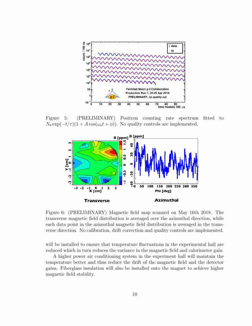
Figure 5: (PRELIMINARY) Positron counting rate spectrum fitted toN0 exp(−t/τ )(1 + A cos(ωat+ φ)). No quality controls are implemented.
Figure 6: (PRELIMINARY) Magnetic field map scanned on May 16th 2018. Thetransverse magnetic field distribution is averaged over the azimuthal direction, whileeach data point in the azimuthal magnetic field distribution is averaged in the trans-verse direction. No calibration, drift correction and quality controls are implemented.
will be installed to ensure that temperature fluctuations in the experimental hall arereduced which in turn reduces the variance in the magnetic field and calorimeter gain.
A higher power air conditioning system in the experiment hall will maintain thetemperature better and thus reduce the drift of the magnetic field and the detectorgains. Fiberglass insulation will also be installed onto the magnet to achieve highermagnetic field stability.
10

5 Conclusion
The Muon g-2 experiment E989 has been successfully commissioned and a Run-1 dataset exceeding the statistics of the E821 experiment has been accumulated.The goal of this experiment is to search for beyond-SM physics by measuring theanomalous magnetic moment aµ of muons with an uncertainty better than 140 ppb.The Run-1 analysis is expected to measure aµ with an uncertainty similar to thatof E821. A dataset several times the size of E821 will be accumulated in 2019 withsignificant improvements in the muon storage efficiency and beam quality.
ACKNOWLEDGEMENTS
We thank David Flay, Erik Swanson, Hogan Nguyen, Jason Crnkovic, Chris Stoughton,Jarek Kaspar, David Hertzog, and Jason Hempstead for their expert knowledge abouteach system of the muon g-2 experiment. We thank the Fermilab management andstaff for their strong support of this experiment.
The Muon g − 2 experiment was performed at the Fermi National AcceleratorLaboratory, a U.S. Department of Energy, Office of Science, HEP User Facility. Fer-milab is managed by Fermi Research Alliance, LLC (FRA), acting under ContractNo. DE-AC02-07CH11359. Additional support for the experiment was providedby the Department of Energy offices of HEP and NP (USA), the National ScienceFoundation (USA), the Istituto Nazionale di Fisica Nucleare (Italy), the Science andTechnology Facilities Council (UK), the Royal Society (UK), the European Union’sHorizon 2020 research and innovation programme under the Marie Sk lodowska-Curiegrant agreements No. 690835 (MUSE), No. 734303 (NEWS), MOST and NSFC(China), MSIP and NRF (Republic of Korea).
References
[1] Julian Schwinger. On quantum-electrodynamics and the magnetic moment ofthe electron. Phys. Rev., 73:416–417, Feb 1948.
[2] D. Hanneke, S. Fogwell, and G. Gabrielse. New measurement of the electronmagnetic moment and the fine structure constant. Phys. Rev. Lett., 100:120801,Mar 2008.
[3] G. W. et. al. Bennett. Final report of the e821 muon anomalous magnetic momentmeasurement at bnl. Phys. Rev. D, 73:072003, Apr 2006.
11
[4] Peter Cox, Chengcheng Han, and Tsutomu T. Yanagida. Muon g − 2 and darkmatter in the minimal supersymmetric standard model. Phys. Rev. D, 98:055015,Sep 2018.
[5] Alexander Keshavarzi, Daisuke Nomura, and Thomas Teubner. Muon g− 2 andα(M2
Z): A new data-based analysis. Phys. Rev. D, 97:114025, Jun 2018.
[6] Friedrich Jegerlehner. The Anomalous Magnetic Moment of the Muon,, volume274 of Springer Tracts in Modern Physics. Springer, 2017.
[7] Michel Davier. e+e results from babar and implications for the muon g-2. NuclearPhysics B - Proceedings Supplements, 253-255:123 – 126, 2014. The TwelfthInternational Workshop on Tau-Lepton Physics (TAU2012).
[8] Thomas Blum, Norman Christ, Masashi Hayakawa, Taku Izubuchi, Luchang Jin,Chulwoo Jung, and Christoph Lehner. Using infinite-volume, continuum qed andlattice qcd for the hadronic light-by-light contribution to the muon anomalousmagnetic moment. Phys. Rev. D, 96:034515, Aug 2017.
[9] Harvey B. Meyer and Hartmut Wittig. Lattice QCD and the anomalous magneticmoment of the muon. 2018.
[10] Gilberto Colangelo, Martin Hoferichter, Massimiliano Procura, and Peter Stoffer.Dispersion relation for hadronic light-by-light scattering: two-pion contributions.Journal of High Energy Physics, 2017(4):161, Apr 2017.
[11] Martin Hoferichter, Bai-Long Hoid, Bastian Kubis, Stefan Leupold, and Sebas-tian P. Schneider. Pion-pole contribution to hadronic light-by-light scattering inthe anomalous magnetic moment of the muon. Phys. Rev. Lett., 121:112002, Sep2018.
[12] J. Grange et al. Muon (g-2) Technical Design Report. 2015.
[13] W. et. al. Liu. High precision measurements of the ground state hyperfine struc-ture interval of muonium and of the muon magnetic moment. Phys. Rev. Lett.,82:711–714, Jan 1999.
[14] Peter J. Mohr, David B. Newell, and Barry N. Taylor. Codata recommendedvalues of the fundamental physical constants: 2014. Rev. Mod. Phys., 88:035009,Sep 2016.
[15] Diktys Stratakis, Mary E. Convery, Carol Johnstone, John Johnstone, James P.Morgan, Dean Still, Jason D. Crnkovic, Vladimir Tishchenko, William M. Morse,and Michael J. Syphers. Accelerator performance analysis of the fermilab muoncampus. Phys. Rev. Accel. Beams, 20:111003, Nov 2017.
12
[16] G.T. Danby and et. al. The brookhaven muon storage ring magnet. NuclearInstruments and Methods in Physics Research Section A: Accelerators, Spec-trometers, Detectors and Associated Equipment, 457(1):151 – 174, 2001.
[17] Matthias W. Smith. Developing the Precision Magnetic Field for the E989 Muong-2 Experiment. PhD thesis, University of Washington, Seattle, 2017.
[18] A. Anastasi et. al. Test of candidate light distributors for the muon (g2) lasercalibration system. Nuclear Instruments and Methods in Physics Research Sec-tion A: Accelerators, Spectrometers, Detectors and Associated Equipment, 788:43– 48, 2015.
[19] Thomas Simon Stuttard. The development, testing and characterisation of astraw tracking detector and readout system for the Fermilab muon g-2 experiment.PhD thesis, University College London, 2018.
13