expansion tanks: extrol expansion tanks · •designed and constructed per asme section viii,...
TRANSCRIPT
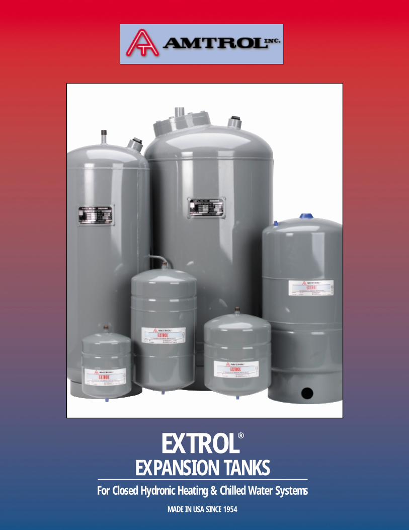
EXTROL®
EXPANSION TANKSFor Closed Hydronic Heating & Chilled Water Systems
MADE IN USA SINCE 1954
AMTROL Quality Expansion Tanks
2
AMTROL Quality Expansion Tanks
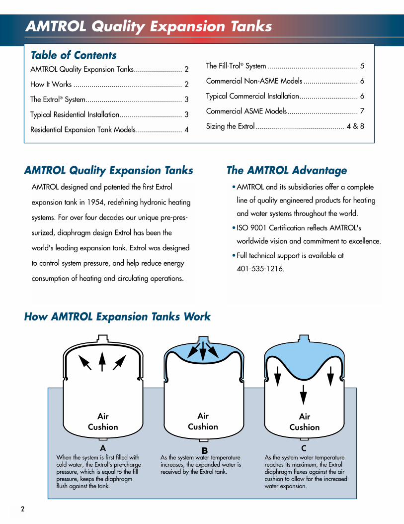
How AMTROL Expansion Tanks Work
AMTROL Quality Expansion Tanks........................ 2
How It Works ...................................................... 2
The Extrol® System................................................ 3
Typical Residential Installation............................... 3
Residential Expansion Tank Models....................... 4
The Fill-Trol® System ............................................. 5
Commercial Non-ASME Models ........................... 6
Typical Commercial Installation............................. 6
Commercial ASME Models................................... 7
Sizing the Extrol ............................................ 4 & 8
AMTROL designed and patented the first Extrol
expansion tank in 1954, redefining hydronic heating
systems. For over four decades our unique pre-pres-
surized, diaphragm design Extrol has been the
world's leading expansion tank. Extrol was designed
to control system pressure, and help reduce energy
consumption of heating and circulating operations.
The AMTROL Advantage•AMTROL and its subsidiaries offer a complete
line of quality engineered products for heating
and water systems throughout the world.
• ISO 9001 Certification reflects AMTROL's
worldwide vision and commitment to excellence.
•Full technical support is available at
401-535-1216.
When the system is first filled withcold water, the Extrol's pre-chargepressure, which is equal to the fillpressure, keeps the diaphragmflush against the tank.
As the system water temperatureincreases, the expanded water isreceived by the Extrol tank.
As the system water temperaturereaches its maximum, the Extroldiaphragm flexes against the aircushion to allow for the increasedwater expansion.
Table of Contents
The Extrol System
3
• Provides separation of system water from air cushion
• Controls system pressure• Butyl diaphragm for superior air retention —
9 times better than natural rubber• No routine maintenance necessary• Provides permanent point of pressure reference
AMTROL Extrol System® Advantages
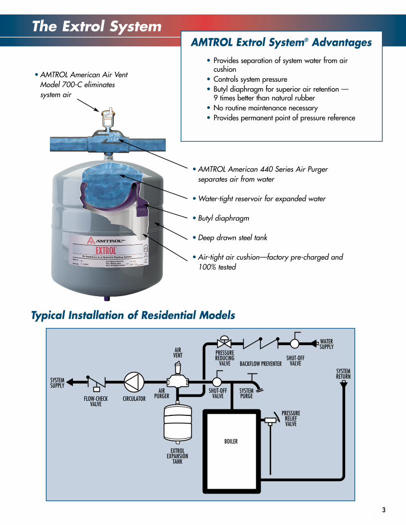
Typical Installation of Residential Models
BOILER
SYSTEMSUPPLY
SYSTEMRETURN
AIRVENT
EXTROLEXPANSION
TANK
AIRPURGER
WATERSUPPLY
PRESSUREREDUCING
VALVESHUT-OFF
VALVE
SHUT-OFFVALVE
BACKFLOW PREVENTER
CIRCULATORFLOW-CHECKVALVE
PRESSURERELIEFVALVE
SYSTEMPURGE
• AMTROL American 440 Series Air Purgerseparates air from water
• Water-tight reservoir for expanded water
• Butyl diaphragm
• Deep drawn steel tank
• Air-tight air cushion—factory pre-charged and100% tested
• AMTROL American Air VentModel 700-C eliminatessystem air
Residential Models and Packages
4
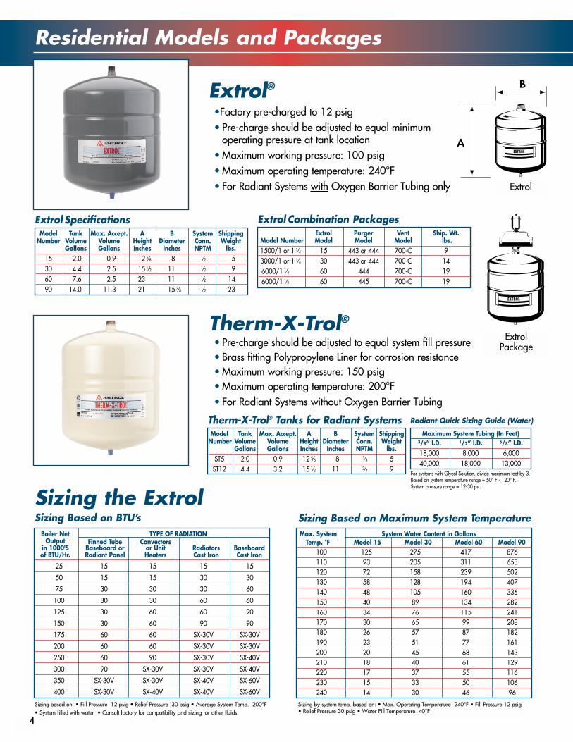
Extrol®•Factory pre-charged to 12 psig• Pre-charge should be adjusted to equal minimum
operating pressure at tank location• Maximum working pressure: 100 psig• Maximum operating temperature: 240°F• For Radiant Systems with Oxygen Barrier Tubing only
Sizing the ExtrolBoiler Net TYPE OF RADIATION
Output Finned Tube Convectorsin 1000'S Baseboard or or Unit Radiators Baseboardof BTU/Hr. Radiant Panel Heaters Cast Iron Cast Iron
25 15 15 15 15
50 15 15 30 30
75 30 30 30 60
100 30 30 60 60
125 30 60 60 90
150 30 60 90 90
175 60 60 SX-30V SX-30V
200 60 60 SX-30V SX-30V
250 60 90 SX-30V SX-40V
300 90 SX-30V SX-30V SX-40V
350 SX-30V SX-30V SX-40V SX-60V
400 SX-30V SX-40V SX-40V SX-60V
Max. System System Water Content in GallonsTemp. °F Model 15 Model 30 Model 60 Model 90
100 125 275 417 876110 93 205 311 653120 72 158 239 502130 58 128 194 407140 48 105 160 336150 40 89 134 282160 34 76 115 241170 30 65 99 208180 26 57 87 182190 23 51 77 161200 20 45 68 143210 18 40 61 129220 17 37 55 116230 15 33 50 106240 14 30 46 96
Sizing Based on BTU’s Sizing Based on Maximum System Temperature
Sizing based on: • Fill Pressure 12 psig • Relief Pressure 30 psig • Average System Temp. 200°F• System filled with water • Consult factory for compatibility and sizing for other fluids.
Sizing by system temp. based on: • Max. Operating Temperature 240°F • Fill Pressure 12 psig• Relief Pressure 30 psig • Water Fill Temperature 40°F
Model Tank Max. Accept. A B System ShippingNumber Volume Volume Height Diameter Conn. Weight
Gallons Gallons Inches Inches NPTM lbs.15 2.0 0.9 12 5⁄8 8 1⁄2 530 4.4 2.5 15 1⁄2 11 1⁄2 960 7.6 2.5 23 11 1⁄2 1490 14.0 11.3 21 15 3⁄8 1⁄2 23
Extrol Specifications
Model Tank Max. Accept. A B System ShippingNumber Volume Volume Height Diameter Conn. Weight
Gallons Gallons Inches Inches NPTM lbs.ST5 2.0 0.9 12 5⁄6 8 3⁄4 5ST12 4.4 3.2 15 1⁄2 11 3⁄4 9
Therm-X-Trol® Tanks for Radiant SystemsMaximum System Tubing (In Feet)
3/8” I.D. 1/2” I.D. 5/8” I.D.18,000 8,000 6,00040,000 18,000 13,000
For systems with Glycol Solution, divide maximum feet by 3.Based on system temperature range = 50° F - 120° F.System pressure range = 12-30 psi.
Radiant Quick Sizing Guide (Water)
Extrol Purger Vent Ship. Wt.Model Number Model Model Model lbs.1500/1 or 1 1⁄4 15 443 or 444 700-C 93000/1 or 1 1⁄4 30 443 or 444 700-C 146000/1 1⁄4 60 444 700-C 196000/1 1⁄2 60 445 700-C 19
Extrol Combination Packages
Extrol
ExtrolPackage
Therm-X-Trol®
• Pre-charge should be adjusted to equal system fill pressure• Brass fitting Polypropylene Liner for corrosion resistance• Maximum working pressure: 150 psig• Maximum operating temperature: 200°F• For Radiant Systems without Oxygen Barrier Tubing
The Fill-Trol System - Expansion Control with Automatic Fill Feature
5
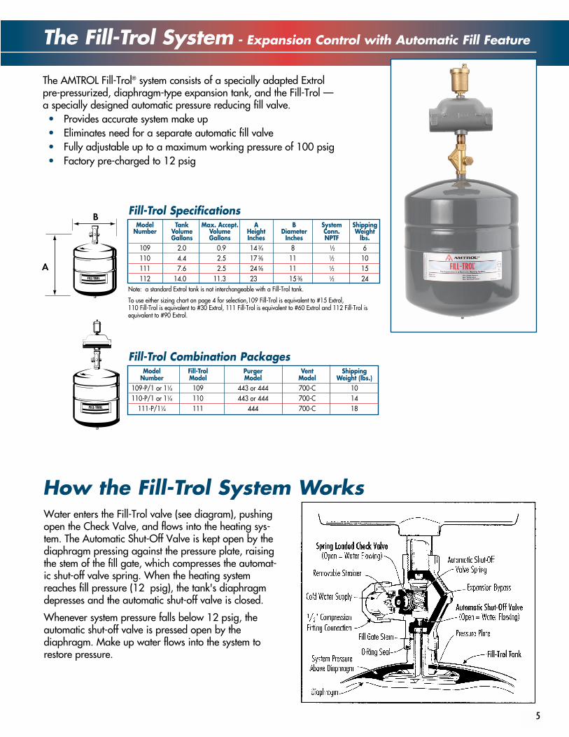
The AMTROL Fill-Trol® system consists of a specially adapted Extrolpre-pressurized, diaphragm-type expansion tank, and the Fill-Trol —a specially designed automatic pressure reducing fill valve.• Provides accurate system make up• Eliminates need for a separate automatic fill valve• Fully adjustable up to a maximum working pressure of 100 psig• Factory pre-charged to 12 psig
How the Fill-Trol System WorksWater enters the Fill-Trol valve (see diagram), pushingopen the Check Valve, and flows into the heating sys-tem. The Automatic Shut-Off Valve is kept open by thediaphragm pressing against the pressure plate, raisingthe stem of the fill gate, which compresses the automat-ic shut-off valve spring. When the heating systemreaches fill pressure (12 psig), the tank's diaphragmdepresses and the automatic shut-off valve is closed.
Whenever system pressure falls below 12 psig, theautomatic shut-off valve is pressed open by thediaphragm. Make up water flows into the system torestore pressure.
Model Tank Max. Accept. A B System ShippingNumber Volume Volume Height Diameter Conn. Weight
Gallons Gallons Inches Inches NPTF lbs.109 2.0 0.9 14 3⁄4 8 1⁄2 6110 4.4 2.5 17 3⁄8 11 1⁄2 10111 7.6 2.5 24 5⁄8 11 1⁄2 15112 14.0 11.3 23 15 3⁄8 1⁄2 24
Note: a standard Extrol tank is not interchangeable with a Fill-Trol tank.
To use either sizing chart on page 4 for selection,109 Fill-Trol is equivalent to #15 Extrol, 110 Fill-Trol is equivalent to #30 Extrol, 111 Fill-Trol is equivalent to #60 Extrol and 112 Fill-Trol isequivalent to #90 Extrol.
Fill-Trol Specifications
Model Fill-Trol Purger Vent ShippingNumber Model Model Model Weight (lbs.)
109-P/1 or 11⁄4 109 443 or 444 700-C 10110-P/1 or 11⁄4 110 443 or 444 700-C 14
111-P/11⁄4 111 444 700-C 18
Fill-Trol Combination Packages
Commercial non-ASME Models
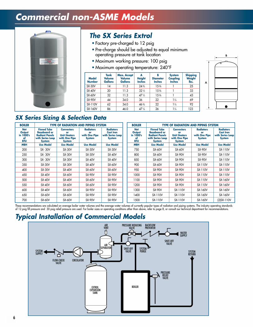
Typical Installation of Commercial Models
The SX Series Extrol
6
BOILER
SYSTEMSUPPLY
SYSTEMRETURN
AIRSEPARATOR
EXTROLEXPANSION
TANK
WATERSUPPLY
PRESSURE REDUCINGVALVE
SHUT-OFFVALVE
SHUT-OFFVALVE
BACKFLOWPREVENTER
CIRCULATORFLOW-CHECKVALVE
PRESSURERELIEFVALVE
SYSTEMPURGE
AIRVENT
Tank Max. Accept A B System ShippingModel Volume Volume Height Diameter Coupling Weight
Number Gallons Gallons Inches Inches Inches lbs.SX-30V 14 11.3 24 3⁄4 15 3⁄8 1 25SX-40V 20 11.3 32 1⁄2 15 3⁄8 1 33SX-60V 32 11.3 47 1⁄2 15 3⁄8 1 43SX-90V 44 34.0 36 22 11⁄4 69SX-110V 62 34.0 46 3⁄4 22 11⁄4 92SX-160V 86 46.0 47 1⁄4 26 11⁄4 123
BOILER TYPE OF RADIATION AND PIPING SYSTEMNet Finned Tube Convectors Radiators Radiators
Output Baseboard or or or Cast Ironin 1000's Radiant Panels Unit Heaters with One Pipe with Series Loop
of with Series Loop with One Pipe System SystemBTU System SystemMBH Use Model Use Model Use Model Use Model
200 SX- 30V SX-30V SX-30V SX-30V
250 SX- 30V SX-30V SX-30V SX-40V
300 SX- 30V SX-30V SX-40V SX-40V
350 SX-30V SX-30V SX-40V SX-60V
400 SX-30V SX-40V SX-60V SX-60V
450 SX-40V SX-60V SX-90V SX-90V
500 SX-40V SX-40V SX-60V SX-90V
550 SX-40V SX-60V SX-60V SX-90V
600 SX-40V SX-60V SX-90V SX-90V
650 SX-60V SX-60V SX-90V SX-90V
700 SX-60V SX-60V SX-90V SX-90V
BOILER TYPE OF RADIATION AND PIPING SYSTEMNet Finned Tube Convectors Radiators Radiators
Output Baseboard or or or Cast Ironin 1000's Radiant Panels Unit Heaters with One Pipe with Series Loop
of with Series Loop with One Pipe System SystemBTU System SystemMBH Use Model Use Model Use Model Use Model
750 SX-60V SX-60V SX-90V SX-110V
800 SX-60V SX-90V SX-90V SX-110V
850 SX-60V SX-90V SX-90V SX-110V
900 SX-60V SX-90V SX-110V SX-110V
950 SX-90V SX-90V SX-110V SX-110V
1000 SX-90V SX-90V SX-110V SX-110V
1100 SX-90V SX-90V SX-110V SX-160V
1200 SX-90V SX-90V SX-110V SX-160V
1300 SX-90V SX-110V SX-160V SX-160V
1400 SX-110V SX-110V SX-160V SX-160V
1500 SX-110V SX-110V SX-160V (2)SX-110V
These recommendations are calculated on average boiler water volumes and the average water volumes of currently popular types of radiation and piping systems. The industry operating standardsof 12 psig fill pressure and 30 psig relief pressure are used. For boiler sizes or operating conditions other than above, refer to page 8, or consult our technical department for recommendations.
SX Series Sizing & Selection Data
• Factory pre-charged to 12 psig• Pre-charge should be adjusted to equal minimum
operating pressure at tank location• Maximum working pressure: 100 psig• Maximum operating temperature: 240°F
Commercial ASME Models
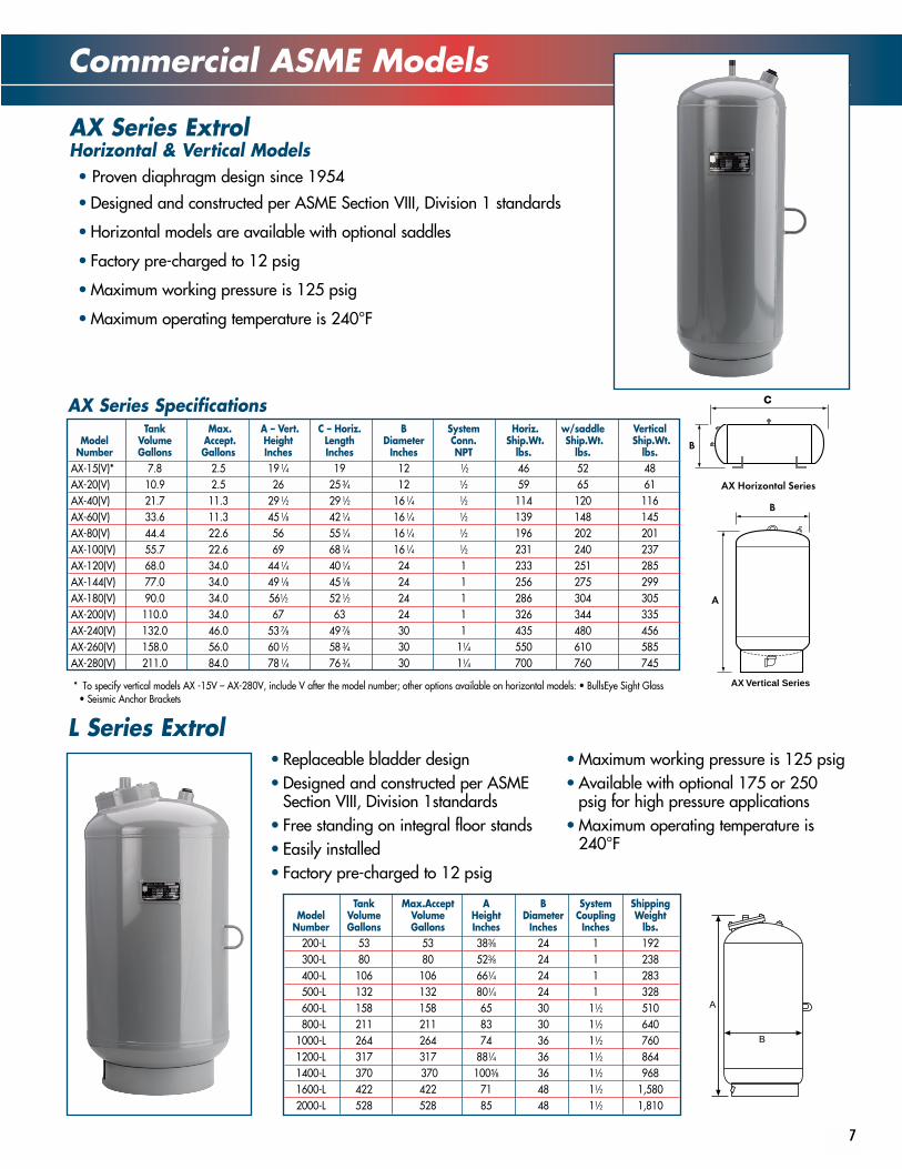
• Proven diaphragm design since 1954
• Designed and constructed per ASME Section VIII, Division 1 standards
• Horizontal models are available with optional saddles
• Factory pre-charged to 12 psig
• Maximum working pressure is 125 psig
• Maximum operating temperature is 240°F
AX Series ExtrolHorizontal & Vertical Models
7
L Series Extrol• Replaceable bladder design• Designed and constructed per ASME
Section VIII, Division 1standards• Free standing on integral floor stands• Easily installed• Factory pre-charged to 12 psig
• Maximum working pressure is 125 psig• Available with optional 175 or 250
psig for high pressure applications• Maximum operating temperature is
240°F
AX Vertical Series
AX Series SpecificationsTank Max. A – Vert. C – Horiz. B System Horiz. w/saddle Vertical
Model Volume Accept. Height Length Diameter Conn. Ship.Wt. Ship.Wt. Ship.Wt.Number Gallons Gallons Inches Inches Inches NPT lbs. lbs. lbs.
AX-15(V)* 7.8 2.5 19 1⁄4 19 12 1⁄2 46 52 48AX-20(V) 10.9 2.5 26 25 3⁄4 12 1⁄2 59 65 61AX-40(V) 21.7 11.3 29 1⁄2 29 1⁄2 16 1⁄4 1⁄2 114 120 116AX-60(V) 33.6 11.3 45 1⁄8 42 1⁄4 16 1⁄4 1⁄2 139 148 145AX-80(V) 44.4 22.6 56 55 1⁄4 16 1⁄4 1⁄2 196 202 201AX-100(V) 55.7 22.6 69 68 1⁄4 16 1⁄4 1⁄2 231 240 237AX-120(V) 68.0 34.0 44 1⁄4 40 1⁄4 24 1 233 251 285AX-144(V) 77.0 34.0 49 1⁄8 45 1⁄8 24 1 256 275 299AX-180(V) 90.0 34.0 561⁄2 52 1⁄2 24 1 286 304 305AX-200(V) 110.0 34.0 67 63 24 1 326 344 335AX-240(V) 132.0 46.0 53 7⁄8 49 7⁄8 30 1 435 480 456AX-260(V) 158.0 56.0 60 1⁄2 58 3⁄4 30 11⁄4 550 610 585AX-280(V) 211.0 84.0 78 1⁄4 76 3⁄4 30 11⁄4 700 760 745
* To specify vertical models AX -15V – AX-280V, include V after the model number; other options available on horizontal models: • BullsEye Sight Glass• Seismic Anchor Brackets
Tank Max.Accept A B System ShippingModel Volume Volume Height Diameter Coupling Weight
Number Gallons Gallons Inches Inches Inches lbs.200-L 53 53 383⁄8 24 1 192300-L 80 80 523⁄8 24 1 238400-L 106 106 661⁄4 24 1 283500-L 132 132 801⁄4 24 1 328600-L 158 158 65 30 11⁄2 510800-L 211 211 83 30 11⁄2 640
1000-L 264 264 74 36 11⁄2 7601200-L 317 317 881⁄4 36 11⁄2 8641400-L 370 370 1005⁄8 36 11⁄2 9681600-L 422 422 71 48 11⁄2 1,5802000-L 528 528 85 48 11⁄2 1,810
A
B
Sizing Commercial Models
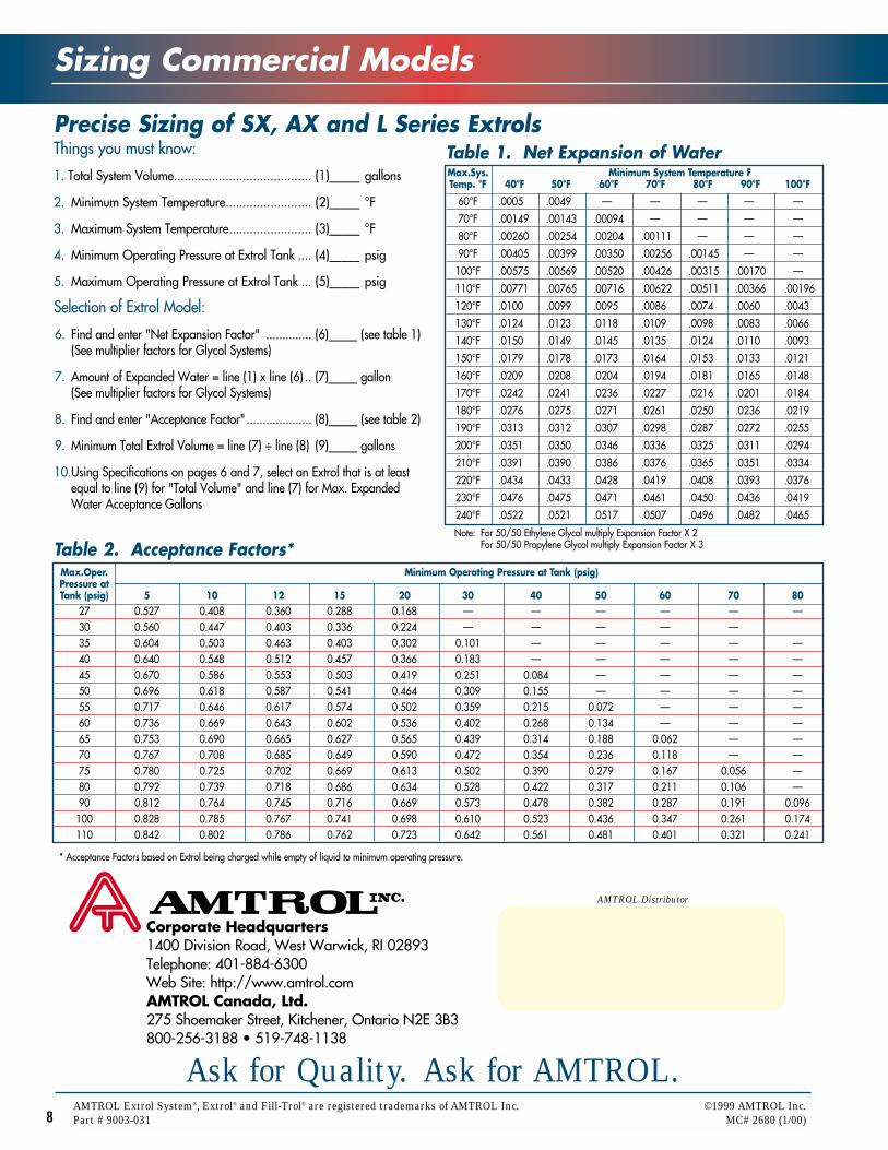
Things you must know:
1. Total System Volume........................................ (1)_____ gallons
2. Minimum System Temperature......................... (2)_____ °F
3. Maximum System Temperature........................ (3)_____ °F
4. Minimum Operating Pressure at Extrol Tank .... (4)_____ psig
5. Maximum Operating Pressure at Extrol Tank ... (5)_____ psig
Selection of Extrol Model:
6. Find and enter "Net Expansion Factor" .............. (6)_____ (see table 1)(See multiplier factors for Glycol Systems)
7. Amount of Expanded Water = line (1) x line (6) .. (7)_____ gallon (See multiplier factors for Glycol Systems)
8. Find and enter "Acceptance Factor".................... (8)_____ (see table 2)
9. Minimum Total Extrol Volume = line (7) ÷ line (8) (9)_____ gallons
10.Using Specifications on pages 6 and 7, select an Extrol that is at least equal to line (9) for "Total Volume" and line (7) for Max. Expanded Water Acceptance Gallons
Precise Sizing of SX, AX and L Series Extrols
8AMTROL Extrol System®, Extrol® and Fill-Trol® are registered trademarks of AMTROL Inc. ©1999 AMTROL Inc.Part # 9003-031 MC# 2680 (1/00)
Corporate Headquarters1400 Division Road, West Warwick, RI 02893Telephone: 401-884-6300Web Site: http://www.amtrol.comAMTROL Canada, Ltd.275 Shoemaker Street, Kitchener, Ontario N2E 3B3800-256-3188 • 519-748-1138
Ask for Quality. Ask for AMTROL.
Table 1. Net Expansion of WaterMax.Sys. Minimum System Temperature FTemp. °F 40°F 50°F 60°F 70°F 80°F 90°F 100°F
60°F .0005 .0049 — — — — —
70°F .00149 .00143 .00094 — — — —
80°F .00260 .00254 .00204 .00111 — — —
90°F .00405 .00399 .00350 .00256 .00145 — —
100°F .00575 .00569 .00520 .00426 .00315 .00170 —
110°F .00771 .00765 .00716 .00622 .00511 .00366 .00196
120°F .0100 .0099 .0095 .0086 .0074 .0060 .0043
130°F .0124 .0123 .0118 .0109 .0098 .0083 .0066
140°F .0150 .0149 .0145 .0135 .0124 .0110 .0093
150°F .0179 .0178 .0173 .0164 .0153 .0133 .0121
160°F .0209 .0208 .0204 .0194 .0181 .0165 .0148
170°F .0242 .0241 .0236 .0227 .0216 .0201 .0184
180°F .0276 .0275 .0271 .0261 .0250 .0236 .0219
190°F .0313 .0312 .0307 .0298 .0287 .0272 .0255
200°F .0351 .0350 .0346 .0336 .0325 .0311 .0294
210°F .0391 .0390 .0386 .0376 .0365 .0351 .0334
220°F .0434 .0433 .0428 .0419 .0408 .0393 .0376
230°F .0476 .0475 .0471 .0461 .0450 .0436 .0419
240°F .0522 .0521 .0517 .0507 .0496 .0482 .0465
Note: For 50/50 Ethylene Glycol multiply Expansion Factor X 2For 50/50 Propylene Glycol multiply Expansion Factor X 3Table 2. Acceptance Factors*
Max.Oper. Minimum Operating Pressure at Tank (psig)Pressure atTank (psig) 5 10 12 15 20 30 40 50 60 70 80
27 0.527 0.408 0.360 0.288 0.168 — — — — — —30 0.560 0.447 0.403 0.336 0.224 — — — — —35 0.604 0.503 0.463 0.403 0.302 0.101 — — — — —40 0.640 0.548 0.512 0.457 0.366 0.183 — — — — —45 0.670 0.586 0.553 0.503 0.419 0.251 0.084 — — — —50 0.696 0.618 0.587 0.541 0.464 0.309 0.155 — — — —55 0.717 0.646 0.617 0.574 0.502 0.359 0.215 0.072 — — —60 0.736 0.669 0.643 0.602 0.536 0.402 0.268 0.134 — — —65 0.753 0.690 0.665 0.627 0.565 0.439 0.314 0.188 0.062 — —70 0.767 0.708 0.685 0.649 0.590 0.472 0.354 0.236 0.118 — —75 0.780 0.725 0.702 0.669 0.613 0.502 0.390 0.279 0.167 0.056 —80 0.792 0.739 0.718 0.686 0.634 0.528 0.422 0.317 0.211 0.106 —90 0.812 0.764 0.745 0.716 0.669 0.573 0.478 0.382 0.287 0.191 0.096100 0.828 0.785 0.767 0.741 0.698 0.610 0.523 0.436 0.347 0.261 0.174110 0.842 0.802 0.786 0.762 0.723 0.642 0.561 0.481 0.401 0.321 0.241
* Acceptance Factors based on Extrol being charged while empty of liquid to minimum operating pressure.
AMTROL Distributor