exp1- the oscilloscopeiust.edu.sy/wp-content/uploads/2018/09/general-physics-ii-lab.pdf · exp1-...
TRANSCRIPT

EXP1- The Oscilloscope
Aim of the experiment
1- To know the principles of the oscilloscope to know how to operate the oscilloscope and
how to use it.
2- To use the oscilloscope to measure the AC and DC potential differences (Voltage), period
and frequency of an electric oscillations.
3- To know how to use the oscilloscope to study the superposition of two periodic motions
(two sine signals) (Lissajous figures).
Devices and Instruments
Oscilloscope
Voltage measuring in oscilloscope
Where: Vp: maximum voltage. Vrms: effective values of voltage. T: period.

Laws of experiment
Vrms = 𝑉𝑝
√2
𝑉𝑝 = 𝐷𝐻
𝑇 = 𝐷𝑋
Where: D: Deflection coefficients. H: Vertical deflection (display height in division).
X: Horizontal spacing in division for one period.
EXP2-Determining the impedance of a capacitor and a resistor
Aim of the experiment
1- Determining the total impedance and phase shift in a series connection of a capacitor and
a resistor.
2- Determining the total impedance and phase shift in a parallel connection of a capacitor
and a resistor.

Devices and Instruments
Oscilloscope
Series connection
Parallel connection
Function generator
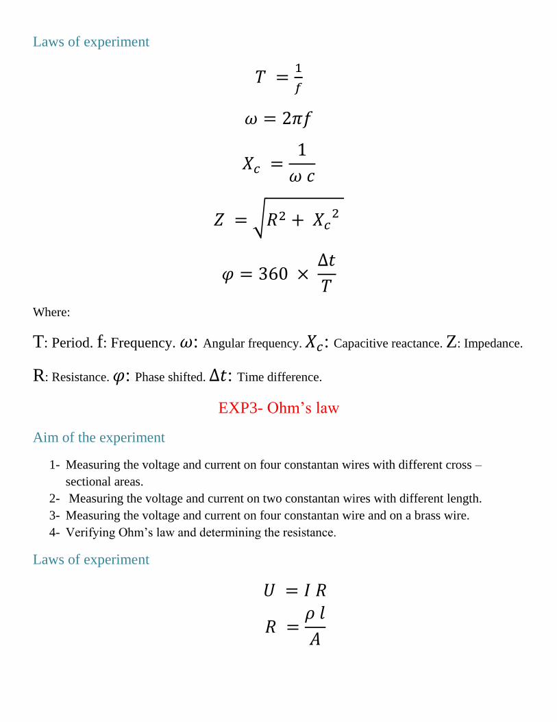
Laws of experiment
𝑇 =1
𝑓
𝜔 = 2𝜋𝑓
𝑋𝑐 =1
𝜔 𝑐
𝑍 = √𝑅2 + 𝑋𝑐2
𝜑 = 360 × ∆𝑡
𝑇
Where:
T: Period. f: Frequency. 𝜔: Angular frequency. 𝑋𝑐: Capacitive reactance. Z: Impedance.
R: Resistance. 𝜑: Phase shifted. ∆𝑡: Time difference.
EXP3- Ohm’s law
Aim of the experiment
1- Measuring the voltage and current on four constantan wires with different cross –
sectional areas.
2- Measuring the voltage and current on two constantan wires with different length.
3- Measuring the voltage and current on four constantan wire and on a brass wire.
4- Verifying Ohm’s law and determining the resistance.
Laws of experiment
𝑈 = 𝐼 𝑅
𝑅 =𝜌 𝑙
𝐴

Where:
U: Voltage. I: Current. R: Resistance. 𝑙: Length of wires. A: Cross sectional area.
𝜌: Specific resistance of the wire material.
Devices and Instruments
Experiment circuit
Volt and Ampere meter
Source

EXP4- Wheatstone bridge
Aim of the experiment
1- Measuring resistance using a bridge called Wheatstone bridge.
2- To determine the equivalent resistance of resistors connected in series.
3- To determine the equivalent resistance of resistors connected in parallel.
Laws of experiment
𝑅𝑥 =𝑅 𝑙1
𝑙2
𝑅𝑥𝑠 = 𝑅1 + 𝑅2 + ⋯ ⋯ ⋯ 1
𝑅𝑥𝑝 =
1
𝑅1+
1
𝑅2+ ⋯ ⋯ ⋯
Where:
𝑅𝑥: Unknown resistance. R, 𝑅1, 𝑅2: Known resistance. 𝑙1, 𝑙2: Length. 𝑅𝑥𝑠:
Series’ resistance law. 𝑅𝑥𝑝: Parallel’s resistance law.
Devices and Instruments
Experiment circuit

Source
Volt and Ampere meter
Wheatstone bridge
Resistance
Variable Resistance

EXP5- Induction by means of a variable magnetic field
Aim of the experiment
1- To determine the induction voltage in a conductor loop as a function of the change
excitation field (respectively the current) generating the magnetic field over time.
2- To determine the induction voltage in a conductor loop as a function of the area of the
loop.
3- To determine the induction voltage in a conductor loop as a function of the number of
windings of the loop.
Laws of experiment
𝑈 = −𝜇0 𝐴 𝑁1 𝑁2
𝐿 𝜕𝐼
𝜕𝑡
Where:
𝑈: Induction Voltage. 𝑁1 , 𝑁2: Numbers of turns. A: Cross sections. L: Length of
coil. 𝜇0: magnetic field constant. 𝜕𝐼
𝜕𝑡: Change over time of the field coil current I.
Devices and Instruments
Experiment circuit

Cassy Lab
Source
Ampere Box
Field coil

Stand for tubes and coils
EXP6- Coulomb’s law
Aim of the experiment
1- Measuring the force between small electrically charged balls as function of their charge if
balls are (+, +), both (-, -) or (+, -).
2- Measuring the force between charged balls as function distance between them.
3- Comparing the measured results with the theoretical values.
Devices and Instruments

Cobra3 basic unit
Newton
Electrometer amplifier

High voltage supply unit
𝐹 = 𝑘 𝑄1 𝑄2
𝑟2
where k is a constant of proportionality, called Coulomb’s constant, k = 8.99 x 10⁹ N.m2 /C2. In
this experiment, you are going to verify the Coulomb’s law by using a Coulomb balance.
𝑄1 ,𝑄2 are the magnitude of the two-point charges, and r is the distance between their centers.
EXP7- Dielectric constant of different materials
Aim of the experiment
1- The relation charge Q and voltage U is to be measured using a plate capacitor.
2- The electric constant ε0 is to be determined from the relation under point 1.
3- The charge of a plate capacitor is to be measured as a function of the inverse of the
distance between the plates, under constant voltage.
4- The relation charge Q and voltage U is to be measured by means of plate capacitor,
between the plates of which different solid dielectric media are introduced. The
corresponding dielectric constants are determined by comparison with measurements
performed with air between the capacitor plates.
Laws of experiment
𝜀0 =𝑄 𝑑
𝐴 𝑈𝑐

𝑄 = 𝐶 𝑈0
Where:
𝑄: Charge of capacitor. A: Cross sections. d: Distance between the plates of the plate
capacitor. 𝜖0: Dielectric constant. 𝑈𝑐: Voltage. C: Capacity of capacitor
Devices and Instruments
High voltage supply unit
Universal measuring amplifier

Plate capacitor
Voltmeter
EXP8- the RLC Circuits
Aim of the experiment
Determination of the frequency performance of a
1- Series – tuned circuit for
a- Voltage resonance without damping resistor,
b- Current resonance without damping resistor,
c- Current resonance with damping resistor,
2- Parallel – tuned circuit for
a- Current resonance without parallel resistor,
b- Voltage resonance without parallel resistor,
c- Voltage resonance with parallel resistor,

Devices and Instruments
Series connection
Parallel connection
Cobra3 basic unit
Function generator

EXP9- Kirchhoff’s Rules
Aim of the experiment
1- Verifying Kirchhoff’s junction rule.
2- Verifying Kirchhoff’s loop rule.
Devices and Instruments
1- Junction rule: the sum of the currents entering any junction in a circuit must equal the
of the currents leaving that junction.
∑ 𝐼𝑖𝑛 = ∑ 𝐼𝑜𝑢𝑡
2- Loop rule: the sum of the potential differences across all elements around any closed-
circuit loop must be zero.
∑ ∆𝑉 = 0

Source
Volt and Ampere meter
Variable Resistance