existing projects review, lower entiat river
TRANSCRIPT
Existing Projects Review
Lower Entiat River
U.S. Department of the Interior Bureau of Reclamation Pacific Northwest Region Pacific Northwest Regional Office Boise, Idaho April 2012

MISSION OF THE U.S. DEPARTMENT OF THE INTERIOR The mission of the Department of the Interior is to protect and provide access to our Nation’s natural and cultural heritage and honor our trust responsibilities to Indian tribes and our commitments to island communities.
MISSION OF THE BUREAU OF RECLAMATION
The mission of the Bureau of Reclamation is to manage, develop, and protect water and related resources in an environmentally and economically sound manner in the interest of the American public.
Photograph on front cover: View of an engineered log structure in the Entiat River.
Existing Projects Review
Lower Entiat River
U.S. Department of the Interior Bureau of Reclamation Pacific Northwest Region Pacific Northwest Regional Office, Boise, Idaho April 2012

April 2012–Existing Project Review i
Table of Contents 1.0 Introduction ....................................................................................................................... 1
Background Information ................................................................................................ 1 Purpose for this Review ................................................................................................. 3
2.0 Assessment ......................................................................................................................... 4 Entiat National Fish Hatchery Complexity Phase I ....................................................... 4
Existing Conditions Assessment ........................................................................ 7 Wilson Side Channel ...................................................................................................... 8
Existing Conditions Assessment ...................................................................... 11 Knapp-Wham Diversion .............................................................................................. 11
Background ...................................................................................................... 12 Existing Conditions Assessment ...................................................................... 15
Small Pond ................................................................................................................... 15 Background ...................................................................................................... 16 Existing Conditions Assessment ...................................................................... 17
Hanan-Detwiler Diversion ........................................................................................... 19 Background ...................................................................................................... 19 Existing Conditions Assessment ...................................................................... 21
Dinkleman Weir ........................................................................................................... 25 Background ...................................................................................................... 25 Existing Conditions Assessment ...................................................................... 26
Bridge-to-Bridge, Phase II (Harrison Side Channel) ................................................... 27 Background ...................................................................................................... 28 Existing Conditions Assessment ...................................................................... 30
Bridge-to-Bridge Phase I (Whitehall Weir) ................................................................. 33 Background ...................................................................................................... 34 Existing Conditions Assessment ...................................................................... 37
NRCS Weirs ................................................................................................................. 38 Background ...................................................................................................... 38 Existing Conditions Assessment ...................................................................... 39
Milne… ........................................................................................................................ 42 Background ...................................................................................................... 43 Existing Conditions Assessment ...................................................................... 47
Yakama Tribe ELJ ....................................................................................................... 50 Background ...................................................................................................... 51 Existing Conditions Assessment ...................................................................... 53
ii Existing Project Review – April 2012
Below the Bridge (Moody Canyon) ............................................................................. 53 Background ...................................................................................................... 54 Existing Conditions Assessment ...................................................................... 58
3.0 Summary ......................................................................................................................... 62 Literature Cited ..................................................................................................................... 64
List of Figures Figure 1. Project area map showing the approximate location of each of the 12 instream project sites assessed in this report. ............................................................................................ 2
Figure 2. Entiat National Fish Hatchery Complexity site map. ................................................. 4
Figure 3. Entiat National Fish Hatchery Complexity. Photo of the levee construction in March 1941 ................................................................................................................................. 5
Figure 4. Entiat National Fish Hatchery Complexity. Photo of the newly completed levee in 1941 along with loose boulder armor installed on the river side of the structure ....................... 6
Figure 5. Entiat National Fish Hatchery Complexity. Photo of slash scattered across the footprint of the levee following removal. ................................................................................... 7
Figure 6. Wilson Side Channel site map. ................................................................................... 9
Figure 7. Wilson Side Channel. Photo of the Wilson side channel inlet culvert nearly overtopped with water in September 2011. .............................................................................. 10
Figure 8. Wilson Side Channel. Photo of the Wilson side channel looking upstream at the point where it passes beneath Roaring Creek Road in September 2011. .................................. 10
Figure 9. Knapp-Wham Diversion site map. ........................................................................... 12
Figure 10. Knapp-Wham Diversion. Final design of the diversion structure, headworks, and sediment sluice. ......................................................................................................................... 13
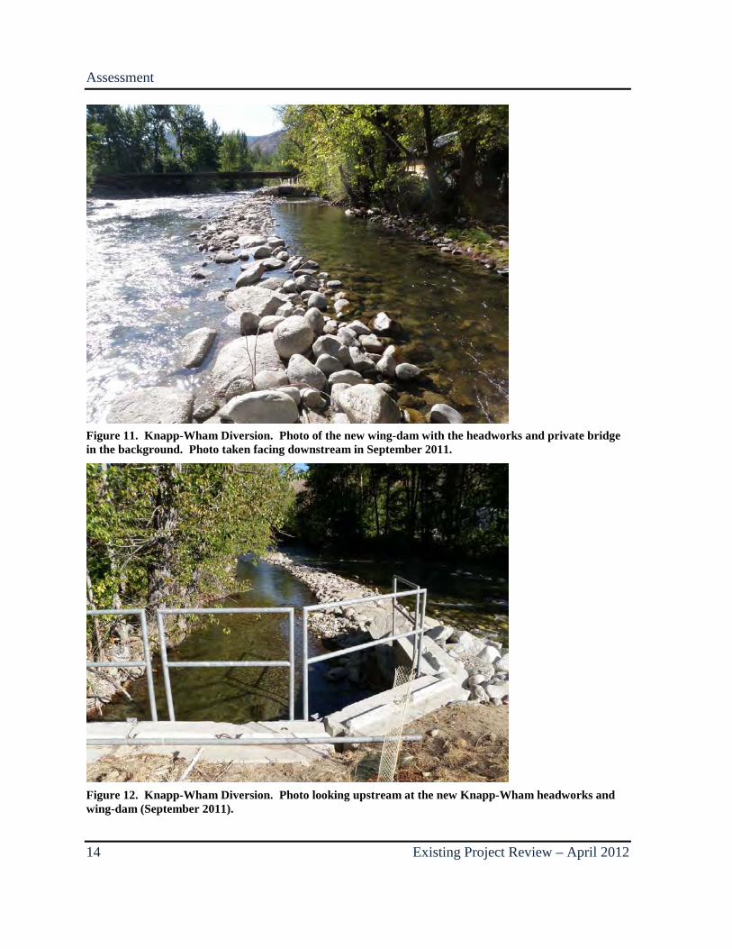
Figure 11. Knapp-Wham Diversion. Photo of the new wing-dam with the headworks and private bridge in the background. ............................................................................................. 14
Figure 12. Knapp-Wham Diversion. Photo looking upstream at the new Knapp-Wham headworks and wing-dam. ........................................................................................................ 14
Figure 13. Small Pond site map. .............................................................................................. 16
Figure 14. Small Pond. Photo looking upstream at the confluence of the pond outlet channel and the Entiat River. ................................................................................................................. 17
Figure 15. Small Pond. Photo of the pond outlet channel near its confluence with the Entiat River taken in July 2011. .......................................................................................................... 18
Figure 16. Hanan-Detwiler Diversion site map. ...................................................................... 19
April 2012–Existing Project Review iii
Figure 17. Hanan-Detwiler Diversion. Final design of the A-shaped cross vane and root wad structures constructed at the Hanan-Detwiler project site........................................................ 20
Figure 18. Hanan-Detwiler Diversion. Bank erosion on the left bank approximately 500 feet downstream of the Hanan-Detwiler diversion. ........................................................................ 21
Figure 19. Hanan-Detwiler Diversion. Photo of Hanan-Detwiler structure in September 2011 .................................................................................................................................................. 22
Figure 20. Hanan-Detwiler Diversion. Photo taken July 2011 looking upstream where boulders were relocated from the structure in order to plug the diversion at the site of the diversion headworks................................................................................................................. 24
Figure 21. Hanan-Detwiler Diversion. Confluence of the dry fish return channel and a perennial side channel of the Entiat River ............................................................................... 24
Figure 22. Dinkleman Weir site map. ..................................................................................... 25
Figure 23. Dinkleman Weir. Photo from October 2005, roughly 4 years after construction. . 26
Figure 24. Dinkleman Weir. Photo from October 2011 roughly 10 years after construction. 27
Figure 25. Bridge-to-Bridge, Phase II (Harrison Side Channel) site map. ............................. 28
Figure 26. Bridge-to-Bridge, Phase II (Harrison Side Channel). Plan view of the final Harrison Side Channel inlet design. ......................................................................................... 29
Figure 27. Bridge-to-Bridge, Phase II (Harrison Side Channel). Design cross section through the inlet channel illustrating the consistent floodplain cut elevation of 853.5 feet. ................. 30
Figure 28. Bridge-to-Bridge, Phase II (Harrison Side Channel). LiDAR view of project area. .......................................................................................................................................... 31
Figure 29. Bridge-to-Bridge, Phase II (Harrison Side Channel). Two-dimensional modeling results illustrating proposed side channel inlet topography and velocity vectors calculated from a 2-year flood................................................................................................................... 31
Figure 30. Bridge-to-Bridge, Phase II (Harrison Side Channel). Sand and gravel deposition at the inlet of the Harrison Side Channell. ............................................................................... 32
Figure 31. Bridge-to-Bridge, Phase II (Harrison Side Channel). Sand and gravel deposition shown at the inlet to Harrison Side Channel ............................................................................ 33
Figure 32. Bridge-to-Bridge Phase I (Whitehall Weir) site map. ........................................... 34
Figure 33. Bridge-to-Bridge Phase I (Whitehall Weir). Plan view of the cross vane design. 35
Figure 34. Bridge-to-Bridge Phase I (Whitehall Weir). Profile view of the cross vane design illustrating the location and shape of the proposed pool. ......................................................... 36
Figure 35. Bridge-to-Bridge Phase I (Whitehall Weir). Photo taken shortly after construction in 2006 looking across the weir from the right bank. .............................................................. 36
Figure 36. Bridge-to-Bridge Phase I (Whitehall Weir). Deposition shown through the throat of the weir (red dashed outline) ............................................................................................... 37

iv Existing Project Review – April 2012
Figure 37. Fire Station Weirs site map. ................................................................................... 38
Figure 38. Fire Station Weirs. Design drawings illustrating the proposed type and location of the two Fire Station cross vanes................................................................................................ 39
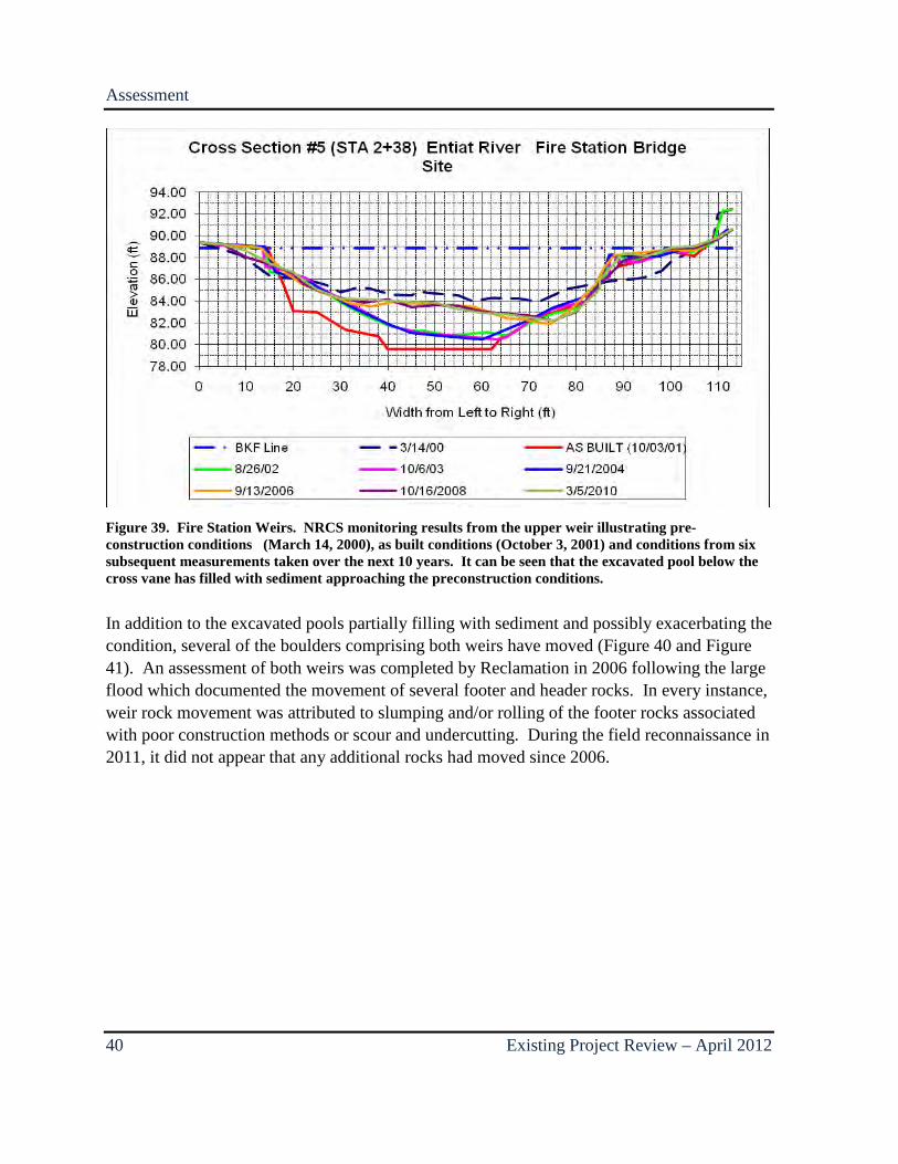
Figure 39. Fire Station Weirs. NRCS monitoring results from the upper weir illustrating pre-construction conditions and conditions from six subsequent measurements taken over the next 10 years ..................................................................................................................................... 40
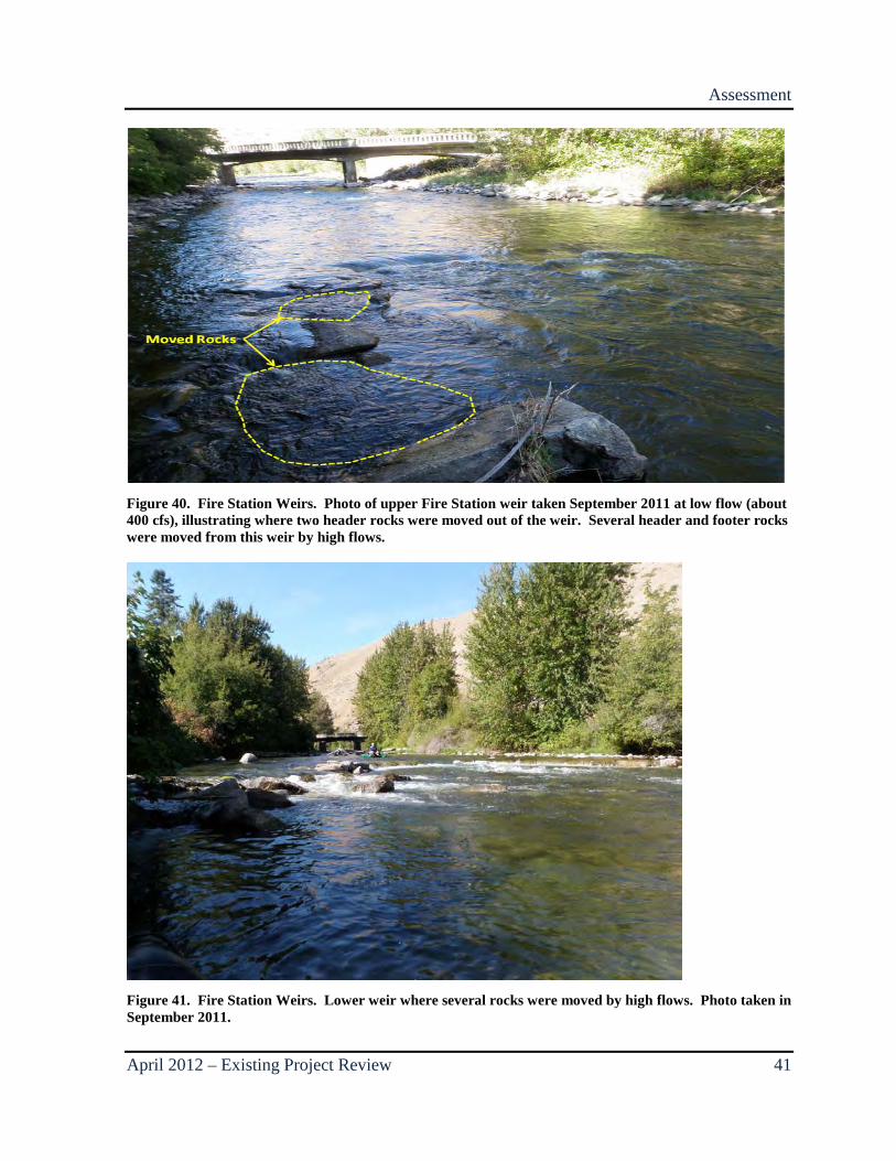
Figure 40. Fire Station Weirs. Photo of upper Fire Station weir taken September 2011 at low flow, illustrating where two header rocks were moved out of the weir. ................................... 41
Figure 41. Fire Station Weirs. Lower weir where several rocks were moved by high flows. Photo taken in September 2011. ............................................................................................... 41
Figure 42. Fire Station Weirs. Photo taken at low water in 2006 illustrating gravel deposition on the left bank in the lee of the lower weir partially burying the LWM structure in this location ...................................................................................................................................... 42
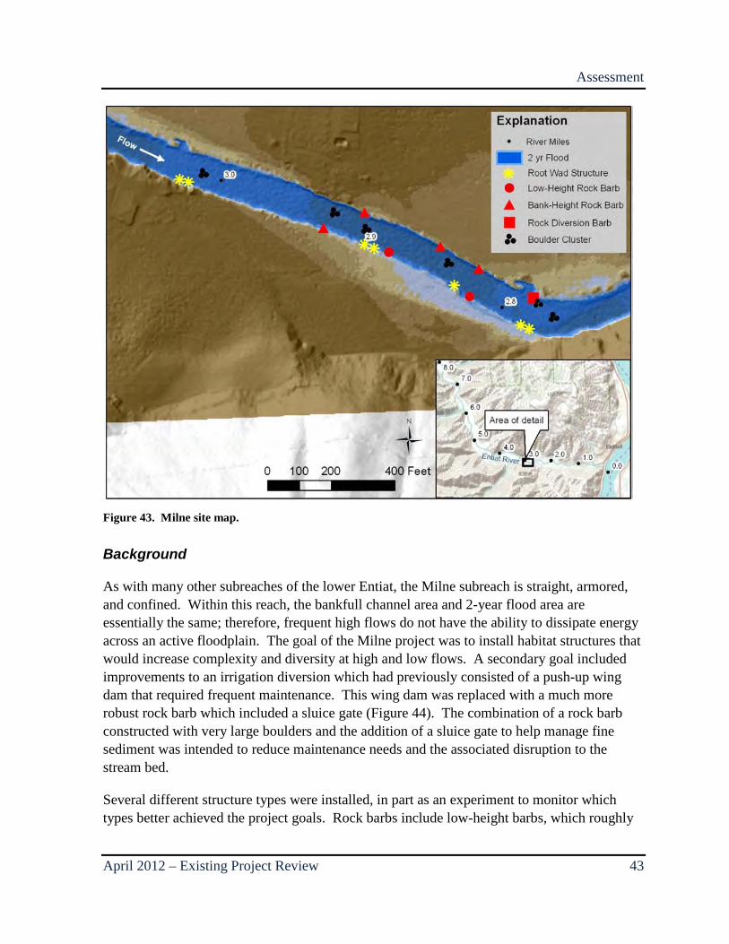
Figure 43. Milne site map. ....................................................................................................... 43
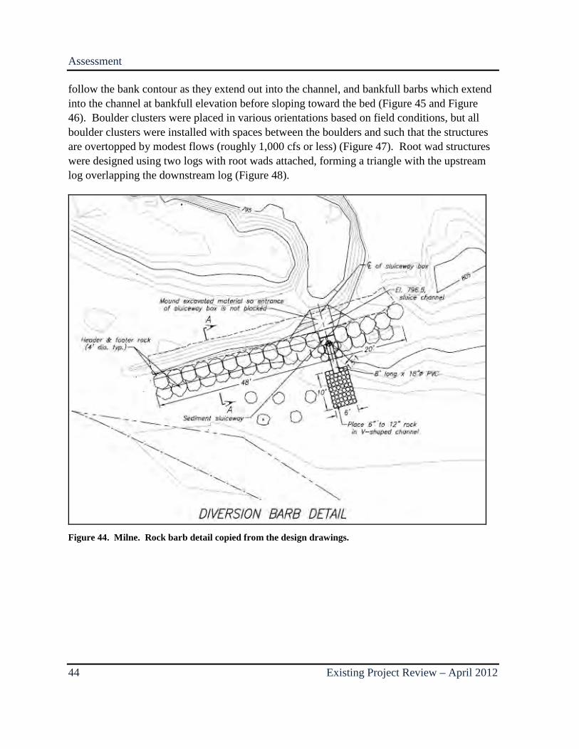
Figure 44. Milne. Rock barb detail copied from the design drawings. ................................... 44
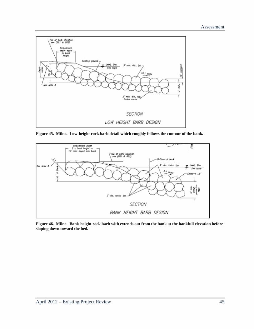
Figure 45. Milne. Low-height rock barb detail which roughly follows the contour of the bank. .......................................................................................................................................... 45
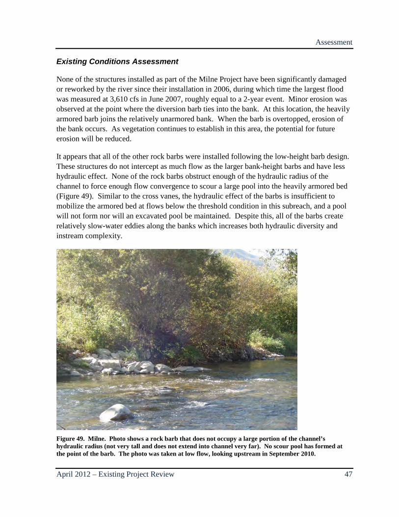
Figure 46. Milne. Bank-height rock barb with extends out from the bank at the bankfull elevation before sloping down toward the bed. ........................................................................ 45
Figure 47. Milne. Boulder cluster looking downstream at low-water .................................... 46
Figure 48. Milne. Pair of root wad structures (each structure consists of two overlapping logs with root wads) ......................................................................................................................... 46
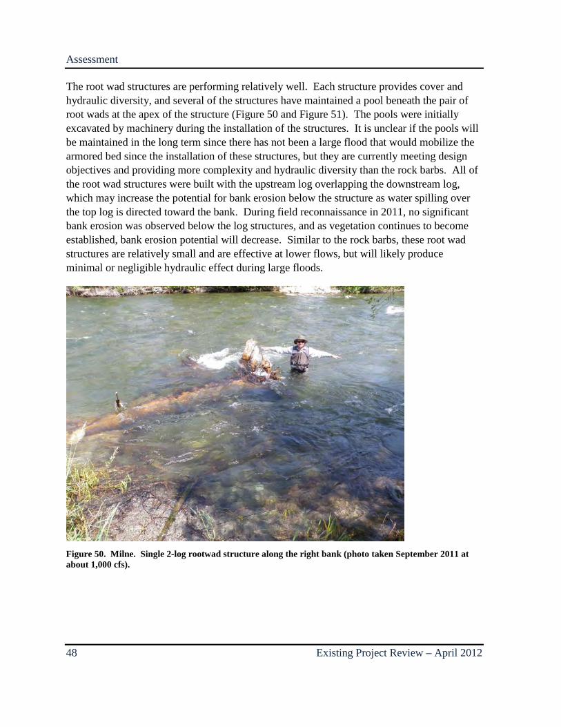
Figure 49. Milne. Photo shows a rock barb that does not occupy a large portion of the channel’s hydraulic radius ........................................................................................................ 47
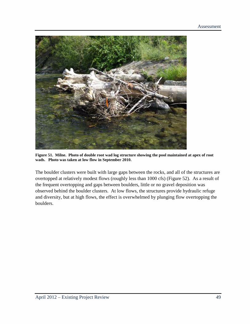
Figure 50. Milne. Single 2-log rootwad structure along the right bank. ................................. 48
Figure 51. Milne. Photo of double root wad log structure showing the pool maintained at apex of root wads. ..................................................................................................................... 49
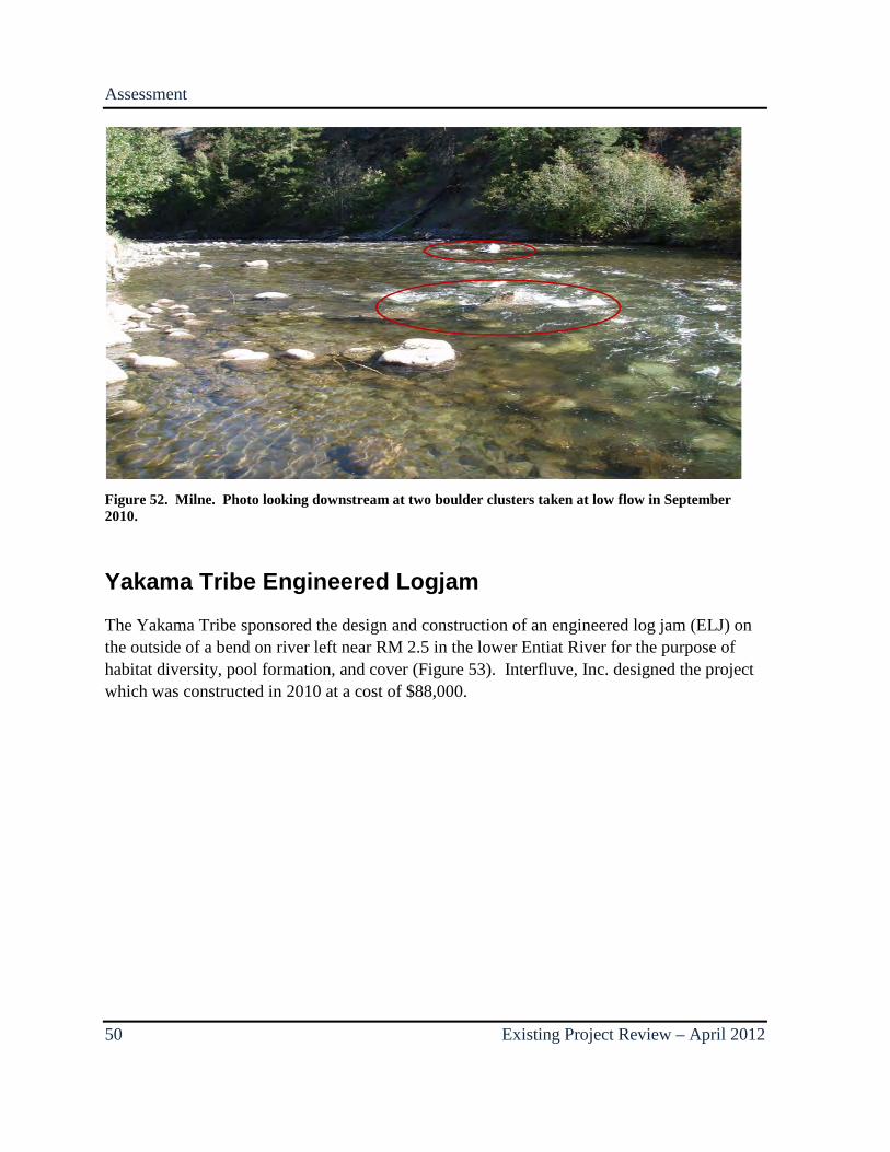
Figure 52. Milne. Photo looking downstream at two boulder clusters taken at low flow in September 2010. ....................................................................................................................... 50
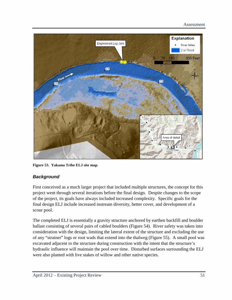
Figure 53. Yakama Tribe ELJ site map. .................................................................................. 51
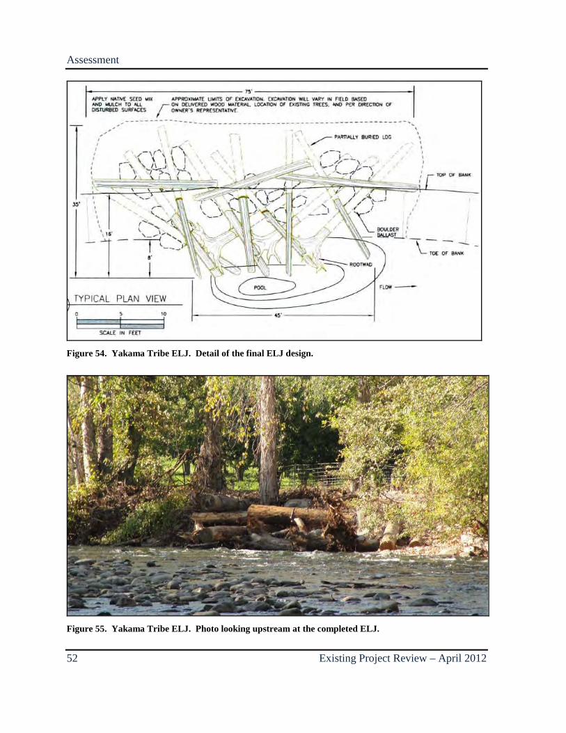
Figure 54. Yakama Tribe ELJ. Detail of the final ELJ design. .............................................. 52
Figure 55. Yakama Tribe ELJ. Photo looking upstream at the completed ELJ. ..................... 52
Figure 56. Below the Bridge site map. .................................................................................... 54
Figure 57. Below the Bridge. Photo of the rock and log diversion structure taken immediately after construction in 2010. ................................................................................... 55

April 2012–Existing Project Review v
Figure 58. Below the Bridge. Photo of a single large boulder with two smaller flanking boulders comprising a single cluster taken at about 1,000 cfs in July 2011 ............................ 56
Figure 59. Below the Bridge. Photo looking upstream at a large woody debris complex on the left bank. ............................................................................................................................. 57
Figure 60. Below the Bridge. Photo of the completed ELJ taken from the left bank at low water in September 2011. ......................................................................................................... 57
Figure 61. Below the Bridge. Photo of the ELJ taken from the right bank of the channel (on the island) in July 2011 at approximately 1000 cfs.................................................................. 58
Figure 62. Below the Bridge. Photo taken in September, 2011 from the Keystone Bridge looking downstream at the diversion structure which had racked large volumes of woody debris. ....................................................................................................................................... 60
Figure 63. Below the Bridge. Photo taken in November 2011 from the right bank at the point of diversion showing the diversion structure after the excess woody debris had been cleared and the incorporated root wads were trimmed. ........................................................................ 60

vi Existing Project Review – April 2012
April 2012– Existing Project Review 1
1.0 INTRODUCTION The Bureau of Reclamation (Reclamation) and Bonneville Power Administration contribute to the implementation of salmonid habitat improvement projects in the Entiat River subbasin to help meet commitments contained in the 2010 Supplemental Federal Columbia River Power System Biological Opinion (NOAA Fisheries Service 2010). This Biological Opinion includes a Reasonable and Prudent Alternative (RPA), or a suite of actions, to protect listed salmon and steelhead across their life cycle. Habitat improvement projects in various Columbia River tributaries are one aspect of this RPA. Reclamation provides technical assistance to states, tribes, federal agencies, and other local partners for identification, design, and construction of stream habitat improvement projects that primarily address streamflow, access, entrainment, and channel complexity limiting factors. Reclamation’s contributions to habitat improvement are all meant to be within the framework of the Federal Columbia River Power System Biological Opinion RPA or related commitments. The assessments described in this report provide scientific information on geomorphology and physical conditions that can be used to adaptively manage existing fish habitat improvement projects and to help ensure those projects function appropriately within the geomorphic and physical context of the lower Entiat River. It should be noted that the ability to effectively assess projects increases over time as projects are exposed to an increasing range of conditions. As a result, the effects of relatively new projects tend to be less well understood than those of more mature projects which have been observed for many years.
Background Information
The Entiat River has been identified as a priority watershed for protection and enhancement of habitat for endangered Upper Columbia River steelhead trout (Oncorhynchus mykiss) and spring Chinook salmon (O. tshawytscha) (NOAA Fisheries Service 2008). Several habitat improvement projects have been completed in the lower 7 miles of the Entiat River by multiple entities since 2001, including 12 projects with an instream habitat component that are assessed in this report (Figure 1).
Introduction
2 Existing Project Review – April 2012
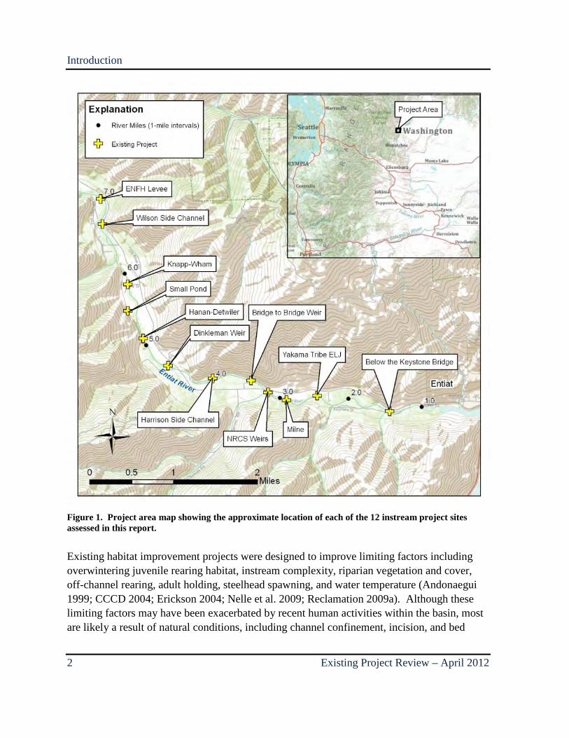
Figure 1. Project area map showing the approximate location of each of the 12 instream project sites assessed in this report.
Existing habitat improvement projects were designed to improve limiting factors including overwintering juvenile rearing habitat, instream complexity, riparian vegetation and cover, off-channel rearing, adult holding, steelhead spawning, and water temperature (Andonaegui 1999; CCCD 2004; Erickson 2004; Nelle et al. 2009; Reclamation 2009a). Although these limiting factors may have been exacerbated by recent human activities within the basin, most are likely a result of natural conditions, including channel confinement, incision, and bed

Introduction
April 2012 – Existing Project Review 3
armoring, that have existed on the lower Entiat River for thousands of years. Consequently, habitat improvement actions should be aimed at improving conditions that affect limiting factors, rather than unrealistically attempting to alter physical conditions that are typical for a stream with the natural character of the lower Entiat River.
Purpose for this Review
This review of existing projects on the lower Entiat River was completed for the purpose of documenting the physical conditions present at each project site to assess each project’s influence on channel character with regard to habitat, channel complexity, and stability. Observed conditions resulting from instream actions will be compared with expectations and project goals as documented from the design reports and personal communications from those involved in the design and implementation of each project. All of the existing projects assessed in this report were completed prior to Reclamation’s Lower Entiat Reach Assessment, which was released in January 2012. Possible revisions to goals and objectives from existing projects are included in this report where appropriate in order to better address reach-scale targets as outlined in the Reach Assessment.
In addition to physical site assessments reported here, several biological monitoring efforts are also currently underway in the lower Entiat River to measure habitat conditions and fish quantity among other biological metrics. It is not the intent of this report to assess the biological conditions of the project sites or summarize existing biological analyses related to these projects.
The results from this largely qualitative assessment of existing conditions are intended to be followed with more robust quantitative topographic survey and options/alternatives for project improvements following collection of the data required for such an effort. It is anticipated that the follow-up analysis and associated report will be completed within 1 year of the release of this report.
Assessment
4 Existing Project Review – April 2012
2.0 ASSESSMENT
Entiat National Fish Hatchery Complexity, Phase 1
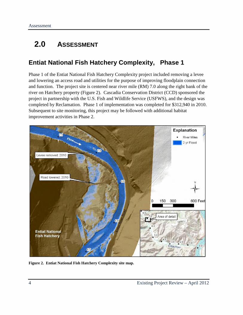
Phase 1 of the Entiat National Fish Hatchery Complexity project included removing a levee and lowering an access road and utilities for the purpose of improving floodplain connection and function. The project site is centered near river mile (RM) 7.0 along the right bank of the river on Hatchery property (Figure 2). Cascadia Conservation District (CCD) sponsored the project in partnership with the U.S. Fish and Wildlife Service (USFWS), and the design was completed by Reclamation. Phase 1 of implementation was completed for $312,940 in 2010. Subsequent to site monitoring, this project may be followed with additional habitat improvement activities in Phase 2.
Figure 2. Entiat National Fish Hatchery Complexity site map.
Assessment
April 2012 – Existing Project Review 5
Background
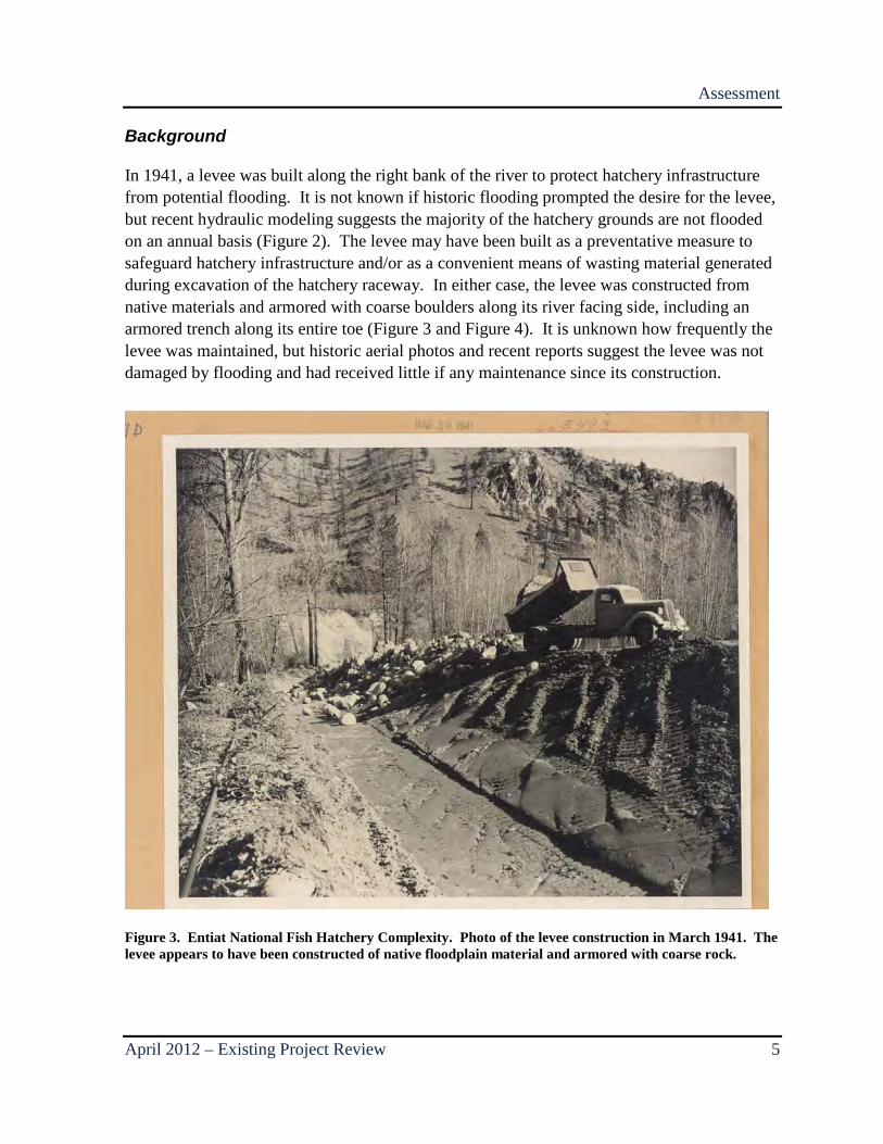
In 1941, a levee was built along the right bank of the river to protect hatchery infrastructure from potential flooding. It is not known if historic flooding prompted the desire for the levee, but recent hydraulic modeling suggests the majority of the hatchery grounds are not flooded on an annual basis (Figure 2). The levee may have been built as a preventative measure to safeguard hatchery infrastructure and/or as a convenient means of wasting material generated during excavation of the hatchery raceway. In either case, the levee was constructed from native materials and armored with coarse boulders along its river facing side, including an armored trench along its entire toe (Figure 3 and Figure 4). It is unknown how frequently the levee was maintained, but historic aerial photos and recent reports suggest the levee was not damaged by flooding and had received little if any maintenance since its construction.
Figure 3. Entiat National Fish Hatchery Complexity. Photo of the levee construction in March 1941. The levee appears to have been constructed of native floodplain material and armored with coarse rock.

Assessment
6 Existing Project Review – April 2012
Figure 4. Entiat National Fish Hatchery Complexity. Photo of the newly completed levee in 1941 along with loose boulder armor installed on the river side of the structure. The Entiat River is located to the left of the levee in this photo and is flowing away from the photographer.
After several decades, including the flood of record in 1948, it was determined that the potential habitat benefit from better floodplain connectivity outweighed the flood protection provided by the levee. In 2008, USFWS, in cooperation with Cascadia Conservation District and Reclamation, developed plans to remove the levee and to lower the elevation of an access road to increase floodplain inundation for the sake of juvenile fish and potential off-channel habitat development. Additionally, plans called for the removal of a small levee along river right at the downstream end of the Hatchery property to facilitate floodwater return flow to the mainstem. A secondary goal of the project was to demonstrate that habitat projects are compatible with infrastructure within the floodplain. The plans were implemented in the summer of 2010 (Figure 5).
Assessment
April 2012 – Existing Project Review 7
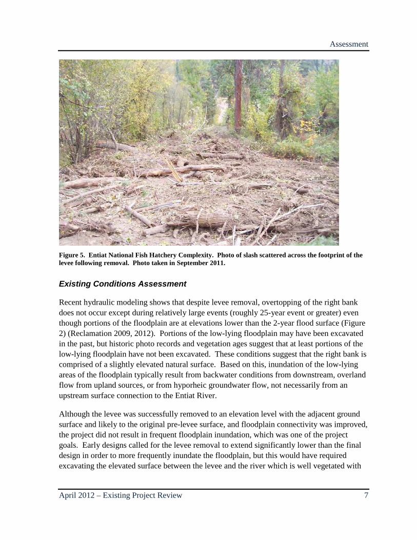
Figure 5. Entiat National Fish Hatchery Complexity. Photo of slash scattered across the footprint of the levee following removal. Photo taken in September 2011.
Existing Conditions Assessment
Recent hydraulic modeling shows that despite levee removal, overtopping of the right bank does not occur except during relatively large events (roughly 25-year event or greater) even though portions of the floodplain are at elevations lower than the 2-year flood surface (Figure 2) (Reclamation 2009, 2012). Portions of the low-lying floodplain may have been excavated in the past, but historic photo records and vegetation ages suggest that at least portions of the low-lying floodplain have not been excavated. These conditions suggest that the right bank is comprised of a slightly elevated natural surface. Based on this, inundation of the low-lying areas of the floodplain typically result from backwater conditions from downstream, overland flow from upland sources, or from hyporheic groundwater flow, not necessarily from an upstream surface connection to the Entiat River.
Although the levee was successfully removed to an elevation level with the adjacent ground surface and likely to the original pre-levee surface, and floodplain connectivity was improved, the project did not result in frequent floodplain inundation, which was one of the project goals. Early designs called for the levee removal to extend significantly lower than the final design in order to more frequently inundate the floodplain, but this would have required excavating the elevated surface between the levee and the river which is well vegetated with
Assessment
8 Existing Project Review – April 2012
mature (hundreds of years old) trees. As constructed, the levee removal reestablishes the historic/natural floodplain surface and inundation potential for the project area.
There have been no observable changes to the river resulting from the removal of the levee, and increased floodplain inundation is not expected except during extreme flood events (greater than 25-year recurrence interval). Lowering of the access road across the floodplain has improved through-flow of surface water and may improve the downstream surface connection in the event of flooding, especially given the partial removal of the lower levee.
Wilson Side Channel
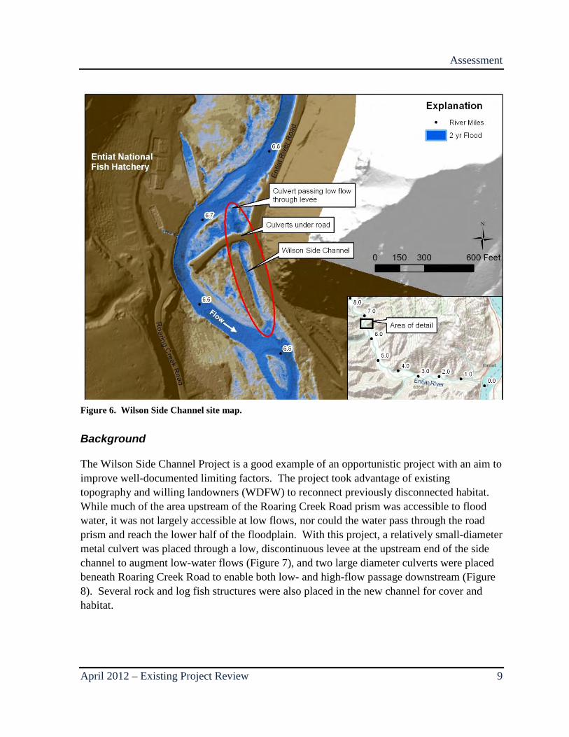
The Wilson Side Channel Project is an off-channel habitat project intended to provide juvenile rearing habitat by accessing previously disconnected low-elevation surfaces through the use of strategically placed culverts, large woody material (LWM), and boulders. The completed side channel provides a minimum estimated 10 cubic feet per second (cfs) of flow through roughly 1,000 feet of rehabilitated side channel passing beneath the Roaring Creek Road via culverts. Located on the left floodplain of the Entiat River near RM 6.7, the project was designed and implemented by the Washington Department of Fish and Wildlife (WDFW) in partnership with Trout Unlimited at a cost of $201,096 and completed in 2004 (Figure 6).
Assessment
April 2012 – Existing Project Review 9
Figure 6. Wilson Side Channel site map.
Background
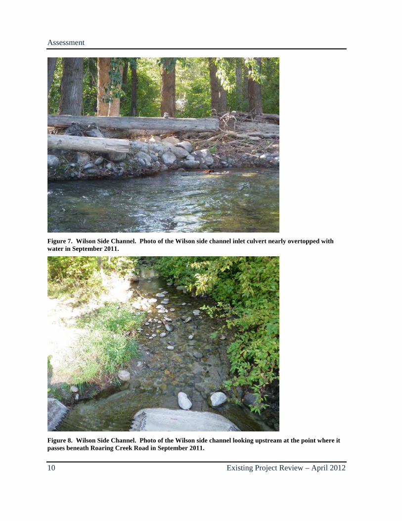
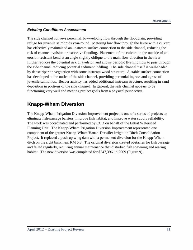
The Wilson Side Channel Project is a good example of an opportunistic project with an aim to improve well-documented limiting factors. The project took advantage of existing topography and willing landowners (WDFW) to reconnect previously disconnected habitat. While much of the area upstream of the Roaring Creek Road prism was accessible to flood water, it was not largely accessible at low flows, nor could the water pass through the road prism and reach the lower half of the floodplain. With this project, a relatively small-diameter metal culvert was placed through a low, discontinuous levee at the upstream end of the side channel to augment low-water flows (Figure 7), and two large diameter culverts were placed beneath Roaring Creek Road to enable both low- and high-flow passage downstream (Figure 8). Several rock and log fish structures were also placed in the new channel for cover and habitat.
Assessment
10 Existing Project Review – April 2012
Figure 7. Wilson Side Channel. Photo of the Wilson side channel inlet culvert nearly overtopped with water in September 2011.
Figure 8. Wilson Side Channel. Photo of the Wilson side channel looking upstream at the point where it passes beneath Roaring Creek Road in September 2011.
Assessment
April 2012 – Existing Project Review 11
Existing Conditions Assessment
The side channel conveys perennial, low-velocity flow through the floodplain, providing refuge for juvenile salmonids year-round. Metering low flow through the levee with a culvert has effectively maintained an upstream surface connection to the side channel, reducing the risk of channel avulsion or excessive flooding. Placement of the culvert on the outside of an erosion-resistant bend at an angle slightly oblique to the main flow direction in the river further reduces the potential risk of avulsion and allows periodic flushing flow to pass through the side channel reducing potential sediment infilling. The side channel itself is well-shaded by dense riparian vegetation with some instream wood structure. A stable surface connection has developed at the outlet of the side channel, providing perennial ingress and egress of juvenile salmonids. Beaver activity has added additional instream structure, resulting in sand deposition in portions of the side channel. In general, the side channel appears to be functioning very well and meeting project goals from a physical perspective.
Knapp-Wham Diversion
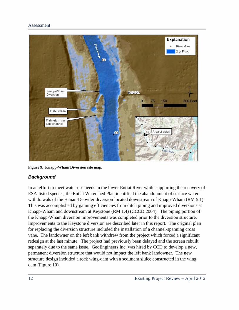
The Knapp-Wham Irrigation Diversion Improvement project is one of a series of projects to eliminate fish-passage barriers, improve fish habitat, and improve water supply reliability. The work was coordinated and performed by CCD on behalf of the Entiat Watershed Planning Unit. The Knapp-Wham Irrigation Diversion Improvement represented one component of the greater Knapp-Wham/Hanan-Detwiler Irrigation Ditch Consolidation Project. It replaced a push-up wing dam with a permanent diversion for the Knapp-Wham ditch on the right bank near RM 5.8. The original diversion created obstacles for fish passage and failed regularly, requiring annual maintenance that disturbed fish spawning and rearing habitat. The new diversion was completed for $247,396 in 2009 (Figure 9).
Assessment
12 Existing Project Review – April 2012
Figure 9. Knapp-Wham Diversion site map.
Background
In an effort to meet water use needs in the lower Entiat River while supporting the recovery of ESA-listed species, the Entiat Watershed Plan identified the abandonment of surface water withdrawals of the Hanan-Detwiler diversion located downstream of Knapp-Wham (RM 5.1). This was accomplished by gaining efficiencies from ditch piping and improved diversions at Knapp-Wham and downstream at Keystone (RM 1.4) (CCCD 2004). The piping portion of the Knapp-Wham diversion improvements was completed prior to the diversion structure. Improvements to the Keystone diversion are described later in this report. The original plan for replacing the diversion structure included the installation of a channel-spanning cross vane. The landowner on the left bank withdrew from the project which forced a significant redesign at the last minute. The project had previously been delayed and the screen rebuilt separately due to the same issue. GeoEngineers Inc. was hired by CCD to develop a new, permanent diversion structure that would not impact the left bank landowner. The new structure design included a rock wing-dam with a sediment sluice constructed in the wing dam (Figure 10).
Assessment
April 2012 – Existing Project Review 13
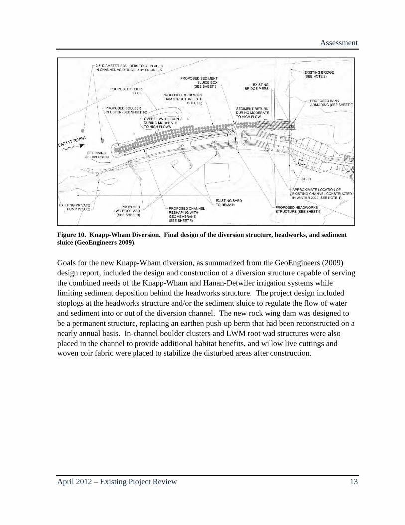
Figure 10. Knapp-Wham Diversion. Final design of the diversion structure, headworks, and sediment sluice (GeoEngineers 2009).
Goals for the new Knapp-Wham diversion, as summarized from the GeoEngineers (2009) design report, included the design and construction of a diversion structure capable of serving the combined needs of the Knapp-Wham and Hanan-Detwiler irrigation systems while limiting sediment deposition behind the headworks structure. The project design included stoplogs at the headworks structure and/or the sediment sluice to regulate the flow of water and sediment into or out of the diversion channel. The new rock wing dam was designed to be a permanent structure, replacing an earthen push-up berm that had been reconstructed on a nearly annual basis. In-channel boulder clusters and LWM root wad structures were also placed in the channel to provide additional habitat benefits, and willow live cuttings and woven coir fabric were placed to stabilize the disturbed areas after construction.
Assessment
14 Existing Project Review – April 2012
Figure 11. Knapp-Wham Diversion. Photo of the new wing-dam with the headworks and private bridge in the background. Photo taken facing downstream in September 2011.
Figure 12. Knapp-Wham Diversion. Photo looking upstream at the new Knapp-Wham headworks and wing-dam (September 2011).

Assessment
April 2012 – Existing Project Review 15
Existing Conditions Assessment
The Knapp-Wham diversion is functioning very well, and should continue to function well in the future, although conditions may change over time, especially following large floods. Key to the success of the structure has been its ability to convey both flow and sediment without significantly altering the hydraulic or sediment transport characteristics of the project site unlike many channel-spanning diversion structures which create a depositional environment upstream of the diveresion. Constructing the tip of the wing dam with large rocks has helped maintain the smaller and slightly lower elevation rocks composing the remainder of the wing dam. The elevation of the wing dam allows overtopping of seasonal high flows, preventing excessive flow and sediment from entering the diversion ditch. Sufficient flow velocity is maintained and sediment deposition at the intake is reduced by allowing high flows to overtop the wing wall, using stoplogs, and building the sediment sluice into the wing-dam adjacent the diversion orifice. The size and location of the headworks orifice structure itself also prevents excessive flow from entering the diversion, because the elevation of the structure matches that of the floodplain, ensuring the diversion will not direct excessive floodwater into the irrigation ditch. The entire floodplain, including the irrigation ditch, will already be inundated before the intake structure is overtopped. Also aiding the function of the diversion is its location in a relatively straight transport-dominated reach with stable banks.
LWM installed in the diversion channel is functioning, but the small size of the LWM root wads potentially limits their habitat benefit. Each structure protrudes from the bank only 2 to 3 feet. Following construction, disturbed areas were planted with riparian vegetation that did not survive. Most of the plantings are still present but completely desiccated, suggesting their roots were not in contact with water.
Small Pond
The Small Pond Project included the excavation of a roughly 0.3-acre spring-fed pond and outlet channel on the floodplain of the Entiat River near RM 5.4. Rock and log habitat structures were installed along the right bank of the Entiat River near the pond channel outlet (Figure 13). The primary purpose of the channel was to provide overwintering juvenile rearing habitat for ESA-listed Chinook salmon and steelhead. The WDFW designed and constructed the project which was completed in 2004 at a cost of $195,842.

Assessment
16 Existing Project Review – April 2012
Figure 13. Small Pond site map.
Background As summarized from personal communication with the WDFW, the main project objective was to develop an off-channel pond for overwintering of spring Chinook salmon and, to a lesser degree, steelhead juveniles. The basis of the design was founded on verbal communications from several WDFW biologists that spring Chinook salmon would overwinter in spring-fed channels and ponds. Providing summer habitat was a secondary goal.
Flows from an existing spring in a wetland/pasture on the property were previously piped to the river. The intent of the project was to dig the pond as large as space allowed and excavate an outlet channel to replace the pipe providing ingress and egress for fish. The main constraints to the project were 1) maintaining a place for the landowner to water horses; 2) avoiding disturbance to the existing orchard; 3) at the landowner’s request, reducing bank erosion upstream and downstream of the mouth of the new pond outlet; and 4) transporting equipment and materials across the Entiat River. The pond has a surface area of about ¼-acre
Assessment
April 2012 – Existing Project Review 17
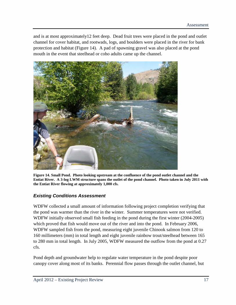
and is at most approximately12 feet deep. Dead fruit trees were placed in the pond and outlet channel for cover habitat, and rootwads, logs, and boulders were placed in the river for bank protection and habitat (Figure 14). A pad of spawning gravel was also placed at the pond mouth in the event that steelhead or coho adults came up the channel.
Figure 14. Small Pond. Photo looking upstream at the confluence of the pond outlet channel and the Entiat River. A 3-log LWM structure spans the outlet of the pond channel. Photo taken in July 2011 with the Entiat River flowing at approximately 1,000 cfs.
Existing Conditions Assessment
WDFW collected a small amount of information following project completion verifying that the pond was warmer than the river in the winter. Summer temperatures were not verified. WDFW initially observed small fish feeding in the pond during the first winter (2004-2005) which proved that fish would move out of the river and into the pond. In February 2006, WDFW sampled fish from the pond, measuring eight juvenile Chinook salmon from 120 to 160 millimeters (mm) in total length and eight juvenile rainbow trout/steelhead between 165 to 280 mm in total length. In July 2005, WDFW measured the outflow from the pond at 0.27 cfs.
Pond depth and groundwater help to regulate water temperature in the pond despite poor canopy cover along most of its banks. Perennial flow passes through the outlet channel, but
Assessment
18 Existing Project Review – April 2012
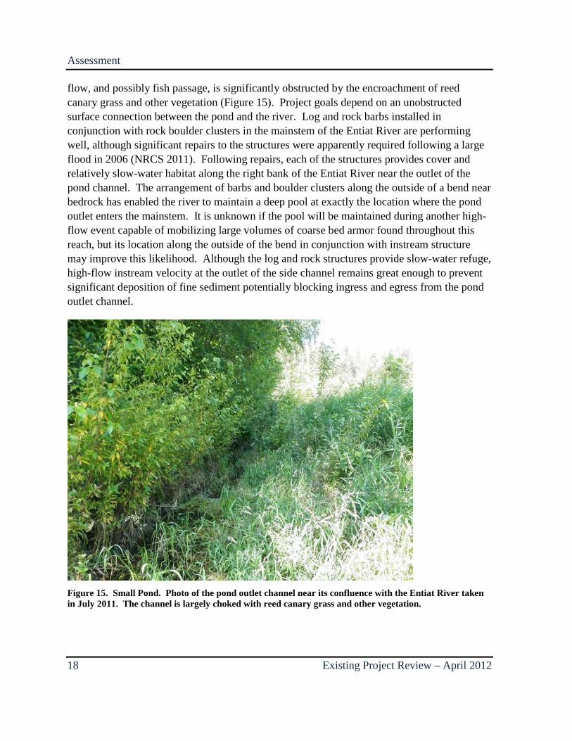
flow, and possibly fish passage, is significantly obstructed by the encroachment of reed canary grass and other vegetation (Figure 15). Project goals depend on an unobstructed surface connection between the pond and the river. Log and rock barbs installed in conjunction with rock boulder clusters in the mainstem of the Entiat River are performing well, although significant repairs to the structures were apparently required following a large flood in 2006 (NRCS 2011). Following repairs, each of the structures provides cover and relatively slow-water habitat along the right bank of the Entiat River near the outlet of the pond channel. The arrangement of barbs and boulder clusters along the outside of a bend near bedrock has enabled the river to maintain a deep pool at exactly the location where the pond outlet enters the mainstem. It is unknown if the pool will be maintained during another high-flow event capable of mobilizing large volumes of coarse bed armor found throughout this reach, but its location along the outside of the bend in conjunction with instream structure may improve this likelihood. Although the log and rock structures provide slow-water refuge, high-flow instream velocity at the outlet of the side channel remains great enough to prevent significant deposition of fine sediment potentially blocking ingress and egress from the pond outlet channel.
Figure 15. Small Pond. Photo of the pond outlet channel near its confluence with the Entiat River taken in July 2011. The channel is largely choked with reed canary grass and other vegetation.
Assessment
April 2012 – Existing Project Review 19
Hanan-Detwiler Diversion
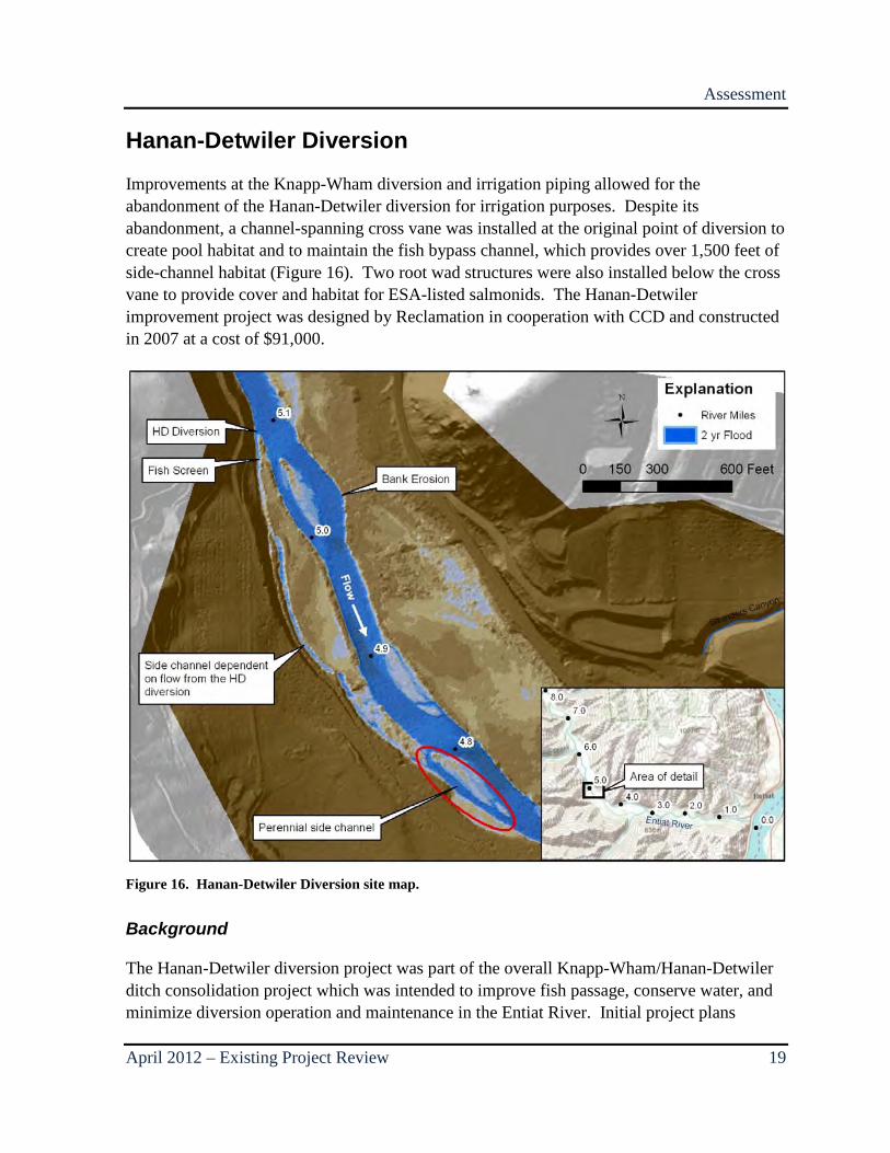
Improvements at the Knapp-Wham diversion and irrigation piping allowed for the abandonment of the Hanan-Detwiler diversion for irrigation purposes. Despite its abandonment, a channel-spanning cross vane was installed at the original point of diversion to create pool habitat and to maintain the fish bypass channel, which provides over 1,500 feet of side-channel habitat (Figure 16). Two root wad structures were also installed below the cross vane to provide cover and habitat for ESA-listed salmonids. The Hanan-Detwiler improvement project was designed by Reclamation in cooperation with CCD and constructed in 2007 at a cost of $91,000.
Figure 16. Hanan-Detwiler Diversion site map.
Background
The Hanan-Detwiler diversion project was part of the overall Knapp-Wham/Hanan-Detwiler ditch consolidation project which was intended to improve fish passage, conserve water, and minimize diversion operation and maintenance in the Entiat River. Initial project plans
Assessment
20 Existing Project Review – April 2012
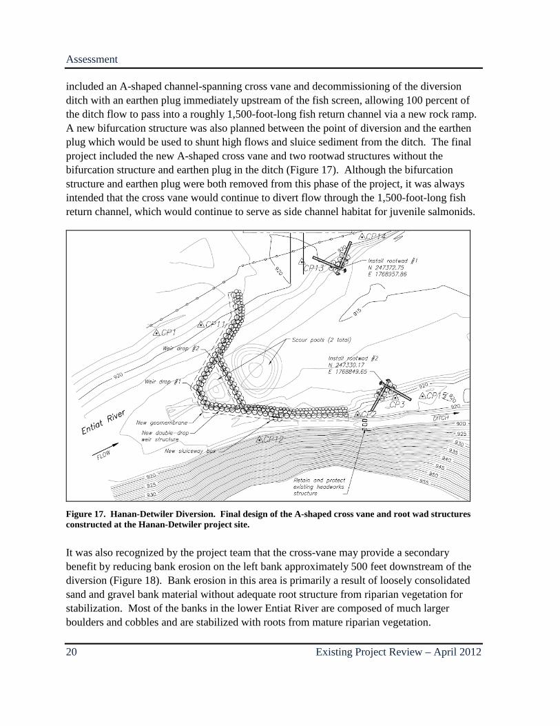
included an A-shaped channel-spanning cross vane and decommissioning of the diversion ditch with an earthen plug immediately upstream of the fish screen, allowing 100 percent of the ditch flow to pass into a roughly 1,500-foot-long fish return channel via a new rock ramp. A new bifurcation structure was also planned between the point of diversion and the earthen plug which would be used to shunt high flows and sluice sediment from the ditch. The final project included the new A-shaped cross vane and two rootwad structures without the bifurcation structure and earthen plug in the ditch (Figure 17). Although the bifurcation structure and earthen plug were both removed from this phase of the project, it was always intended that the cross vane would continue to divert flow through the 1,500-foot-long fish return channel, which would continue to serve as side channel habitat for juvenile salmonids.
Figure 17. Hanan-Detwiler Diversion. Final design of the A-shaped cross vane and root wad structures constructed at the Hanan-Detwiler project site.
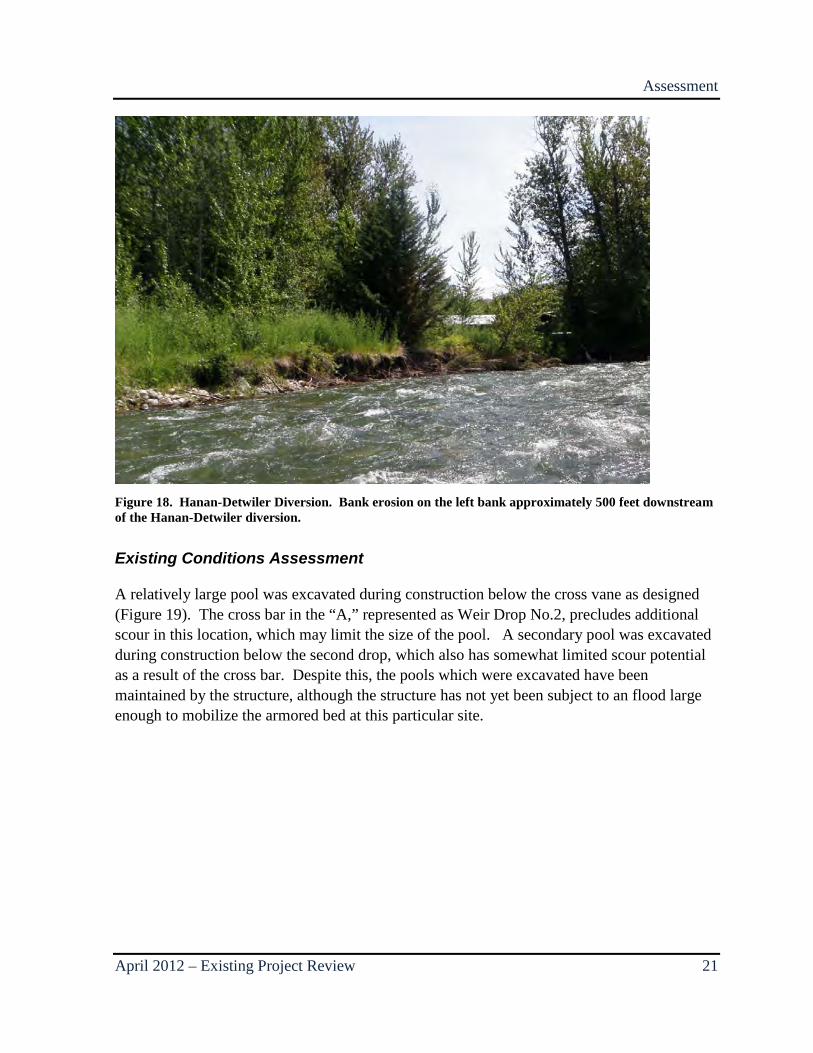
It was also recognized by the project team that the cross-vane may provide a secondary benefit by reducing bank erosion on the left bank approximately 500 feet downstream of the diversion (Figure 18). Bank erosion in this area is primarily a result of loosely consolidated sand and gravel bank material without adequate root structure from riparian vegetation for stabilization. Most of the banks in the lower Entiat River are composed of much larger boulders and cobbles and are stabilized with roots from mature riparian vegetation.
Assessment
April 2012 – Existing Project Review 21
Figure 18. Hanan-Detwiler Diversion. Bank erosion on the left bank approximately 500 feet downstream of the Hanan-Detwiler diversion.
Existing Conditions Assessment
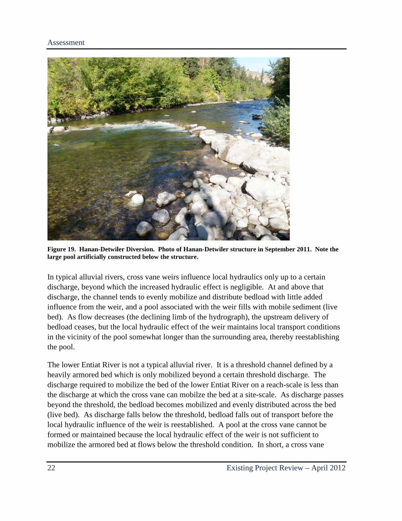
A relatively large pool was excavated during construction below the cross vane as designed (Figure 19). The cross bar in the “A,” represented as Weir Drop No.2, precludes additional scour in this location, which may limit the size of the pool. A secondary pool was excavated during construction below the second drop, which also has somewhat limited scour potential as a result of the cross bar. Despite this, the pools which were excavated have been maintained by the structure, although the structure has not yet been subject to an flood large enough to mobilize the armored bed at this particular site.
Assessment
22 Existing Project Review – April 2012
Figure 19. Hanan-Detwiler Diversion. Photo of Hanan-Detwiler structure in September 2011. Note the large pool artificially constructed below the structure.
In typical alluvial rivers, cross vane weirs influence local hydraulics only up to a certain discharge, beyond which the increased hydraulic effect is negligible. At and above that discharge, the channel tends to evenly mobilize and distribute bedload with little added influence from the weir, and a pool associated with the weir fills with mobile sediment (live bed). As flow decreases (the declining limb of the hydrograph), the upstream delivery of bedload ceases, but the local hydraulic effect of the weir maintains local transport conditions in the vicinity of the pool somewhat longer than the surrounding area, thereby reestablishing the pool.
The lower Entiat River is not a typical alluvial river. It is a threshold channel defined by a heavily armored bed which is only mobilized beyond a certain threshold discharge. The discharge required to mobilize the bed of the lower Entiat River on a reach-scale is less than the discharge at which the cross vane can mobilze the bed at a site-scale. As discharge passes beyond the threshold, the bedload becomes mobilized and evenly distributed across the bed (live bed). As discharge falls below the threshold, bedload falls out of transport before the local hydraulic influence of the weir is reestablished. A pool at the cross vane cannot be formed or maintained because the local hydraulic effect of the weir is not sufficient to mobilize the armored bed at flows below the threshold condition. In short, a cross vane
Assessment
April 2012 – Existing Project Review 23
installed in the lower Entiat River that is not capable of mobilizing the bed armor at a discharge lower than the threshold condition will not be able to form and maintain a pool over the long term. The threshold condition may vary between sites, but is defined by the discharge required to mobilize the bed at that location.
At the time of this report, the Hanan-Detwiler cross-vane has not been subjected to a flood that exceeded the threshold discharge capable of mobilizing the bed in this reach; consequently, the pools, which were excavated by machinery, remain open. Other cross-vanes which were subjected to a significant flood in 2006 have partially or completely filled with bedload sediment. It is anticipated that the pools associated with this cross-vane will also partially or completely fill with bedload sediment during the next threshold event.
The two root-wad structures were both present during field investigations in 2011, although both occupy only a relatively small area of the eddy formed by the cross vane. Neither root wad structure has resulted in the formation of a secondary scour pool, but both are providing cover in the relatively slow-velocity flow on the margins of the channel below the weir.
Bank erosion continues to occur on the left bank below the structure, but there is no evidence that the weir and root wads are exacerbating the condition.
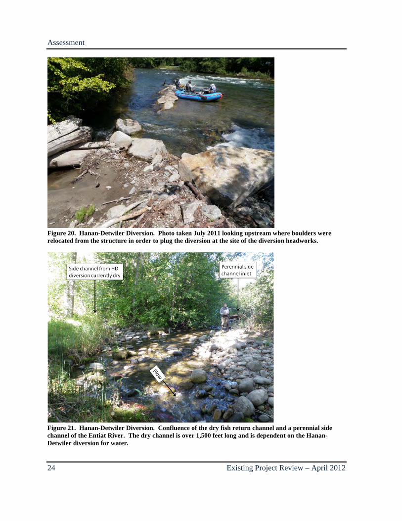
Most notable at the Hanan-Detwiler Project site is the fact that at some point in early 2011, the diversion was mechanically plugged with soil and large boulders at the location of the existing headworks which were abandoned in place. Several of the boulders used to plug the diversion were taken from the right wing of the weir, potentially reducing its effectiveness and stability (Figure 20). Additionally, because the diversion ditch was plugged at the headworks, the entire fish return channel was rendered dry, voiding one of the principal goals of the project. The now dry fish return channel rejoins the Entiat River at the site of a perennial side channel over 1,500 feet downstream of the diversion site (Figure 21).
Assessment
24 Existing Project Review – April 2012
Figure 20. Hanan-Detwiler Diversion. Photo taken July 2011 looking upstream where boulders were relocated from the structure in order to plug the diversion at the site of the diversion headworks.
Figure 21. Hanan-Detwiler Diversion. Confluence of the dry fish return channel and a perennial side channel of the Entiat River. The dry channel is over 1,500 feet long and is dependent on the Hanan-Detwiler diversion for water.
Assessment
April 2012 – Existing Project Review 25
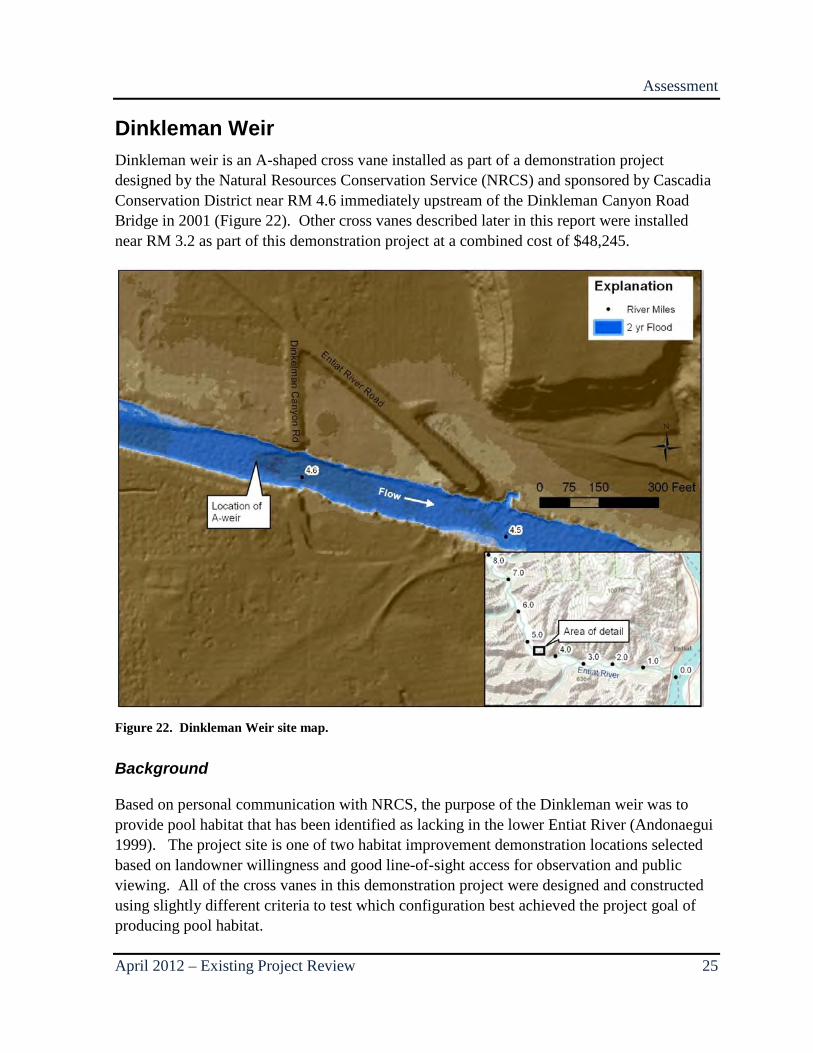
Dinkleman Weir Dinkleman weir is an A-shaped cross vane installed as part of a demonstration project designed by the Natural Resources Conservation Service (NRCS) and sponsored by Cascadia Conservation District near RM 4.6 immediately upstream of the Dinkleman Canyon Road Bridge in 2001 (Figure 22). Other cross vanes described later in this report were installed near RM 3.2 as part of this demonstration project at a combined cost of $48,245.
Figure 22. Dinkleman Weir site map.
Background
Based on personal communication with NRCS, the purpose of the Dinkleman weir was to provide pool habitat that has been identified as lacking in the lower Entiat River (Andonaegui 1999). The project site is one of two habitat improvement demonstration locations selected based on landowner willingness and good line-of-sight access for observation and public viewing. All of the cross vanes in this demonstration project were designed and constructed using slightly different criteria to test which configuration best achieved the project goal of producing pool habitat.
Assessment
26 Existing Project Review – April 2012
The Dinkleman weir was designed as an A-shaped weir with two drops in order to prevent potential fish passage barriers in this relatively steep-gradient reach. The structure itself was designed with a 25° deflection angle (where 0° is parallel to flow) with right and left weir arms sloping at 4.1 percent and 3.8 percent respectively. Larger rocks were used for the Dinkleman weir compared with the other demonstration weirs. To ensure project goals were met, at least for the short term, a large pool was excavated below the weir at the time of its construction.
Existing Conditions Assessment
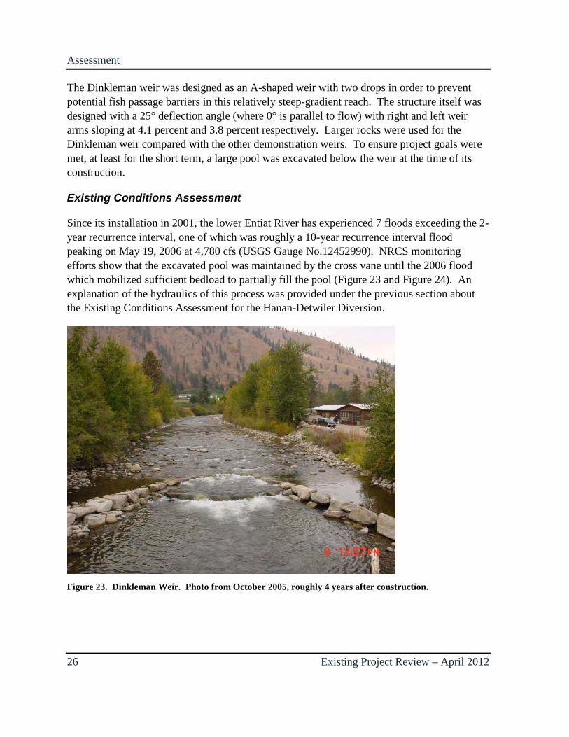
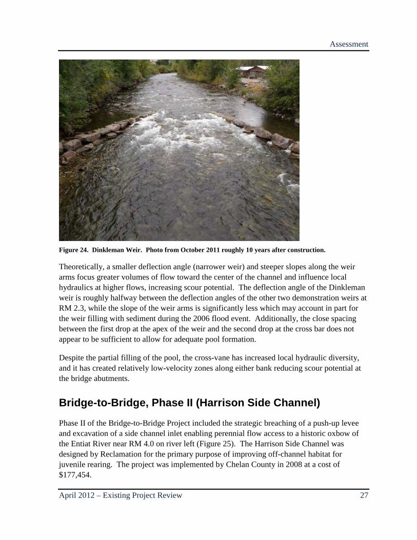
Since its installation in 2001, the lower Entiat River has experienced 7 floods exceeding the 2-year recurrence interval, one of which was roughly a 10-year recurrence interval flood peaking on May 19, 2006 at 4,780 cfs (USGS Gauge No.12452990). NRCS monitoring efforts show that the excavated pool was maintained by the cross vane until the 2006 flood which mobilized sufficient bedload to partially fill the pool (Figure 23 and Figure 24). An explanation of the hydraulics of this process was provided under the previous section about the Existing Conditions Assessment for the Hanan-Detwiler Diversion.
Figure 23. Dinkleman Weir. Photo from October 2005, roughly 4 years after construction.
Assessment
April 2012 – Existing Project Review 27
Figure 24. Dinkleman Weir. Photo from October 2011 roughly 10 years after construction.
Theoretically, a smaller deflection angle (narrower weir) and steeper slopes along the weir arms focus greater volumes of flow toward the center of the channel and influence local hydraulics at higher flows, increasing scour potential. The deflection angle of the Dinkleman weir is roughly halfway between the deflection angles of the other two demonstration weirs at RM 2.3, while the slope of the weir arms is significantly less which may account in part for the weir filling with sediment during the 2006 flood event. Additionally, the close spacing between the first drop at the apex of the weir and the second drop at the cross bar does not appear to be sufficient to allow for adequate pool formation.
Despite the partial filling of the pool, the cross-vane has increased local hydraulic diversity, and it has created relatively low-velocity zones along either bank reducing scour potential at the bridge abutments.
Bridge-to-Bridge, Phase II (Harrison Side Channel)
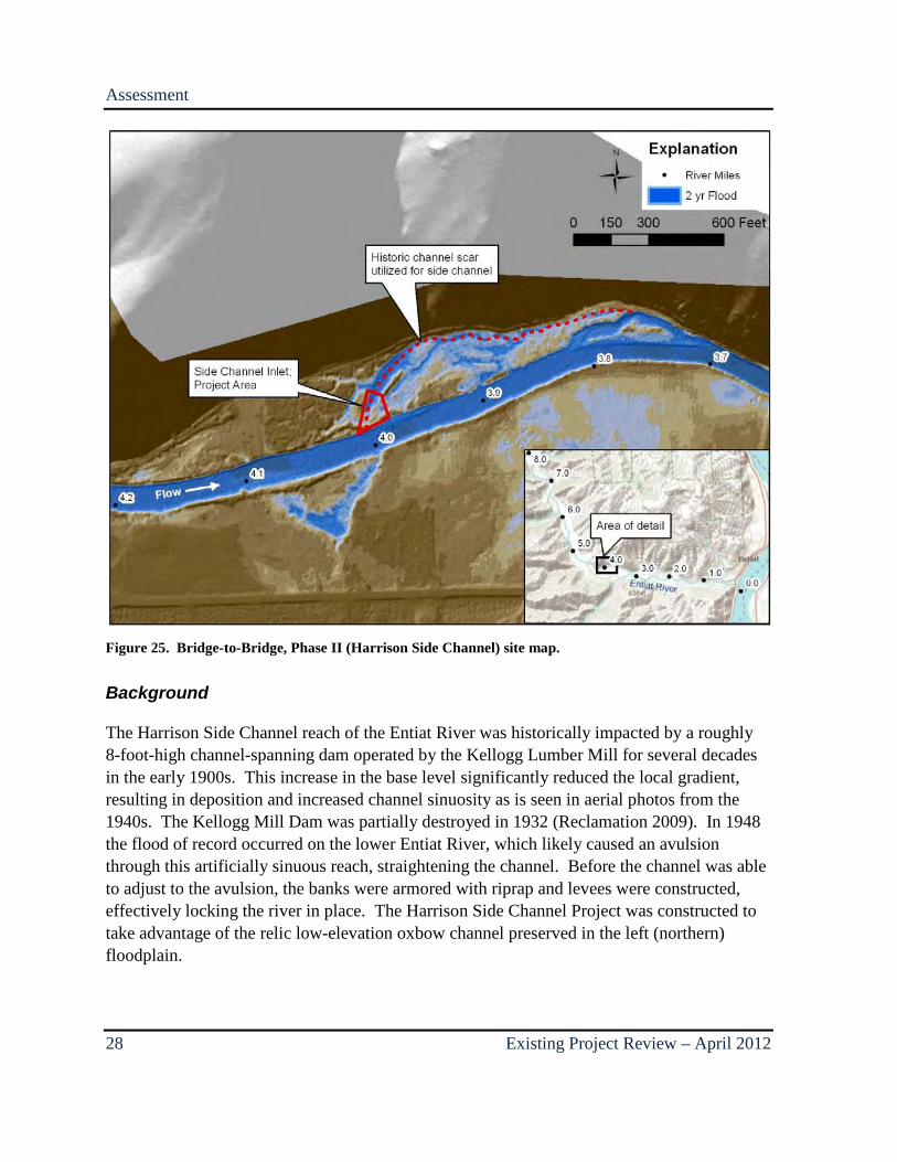
Phase II of the Bridge-to-Bridge Project included the strategic breaching of a push-up levee and excavation of a side channel inlet enabling perennial flow access to a historic oxbow of the Entiat River near RM 4.0 on river left (Figure 25). The Harrison Side Channel was designed by Reclamation for the primary purpose of improving off-channel habitat for juvenile rearing. The project was implemented by Chelan County in 2008 at a cost of $177,454.
Assessment
28 Existing Project Review – April 2012
Figure 25. Bridge-to-Bridge, Phase II (Harrison Side Channel) site map.
Background
The Harrison Side Channel reach of the Entiat River was historically impacted by a roughly 8-foot-high channel-spanning dam operated by the Kellogg Lumber Mill for several decades in the early 1900s. This increase in the base level significantly reduced the local gradient, resulting in deposition and increased channel sinuosity as is seen in aerial photos from the 1940s. The Kellogg Mill Dam was partially destroyed in 1932 (Reclamation 2009). In 1948 the flood of record occurred on the lower Entiat River, which likely caused an avulsion through this artificially sinuous reach, straightening the channel. Before the channel was able to adjust to the avulsion, the banks were armored with riprap and levees were constructed, effectively locking the river in place. The Harrison Side Channel Project was constructed to take advantage of the relic low-elevation oxbow channel preserved in the left (northern) floodplain.
Assessment
April 2012 – Existing Project Review 29
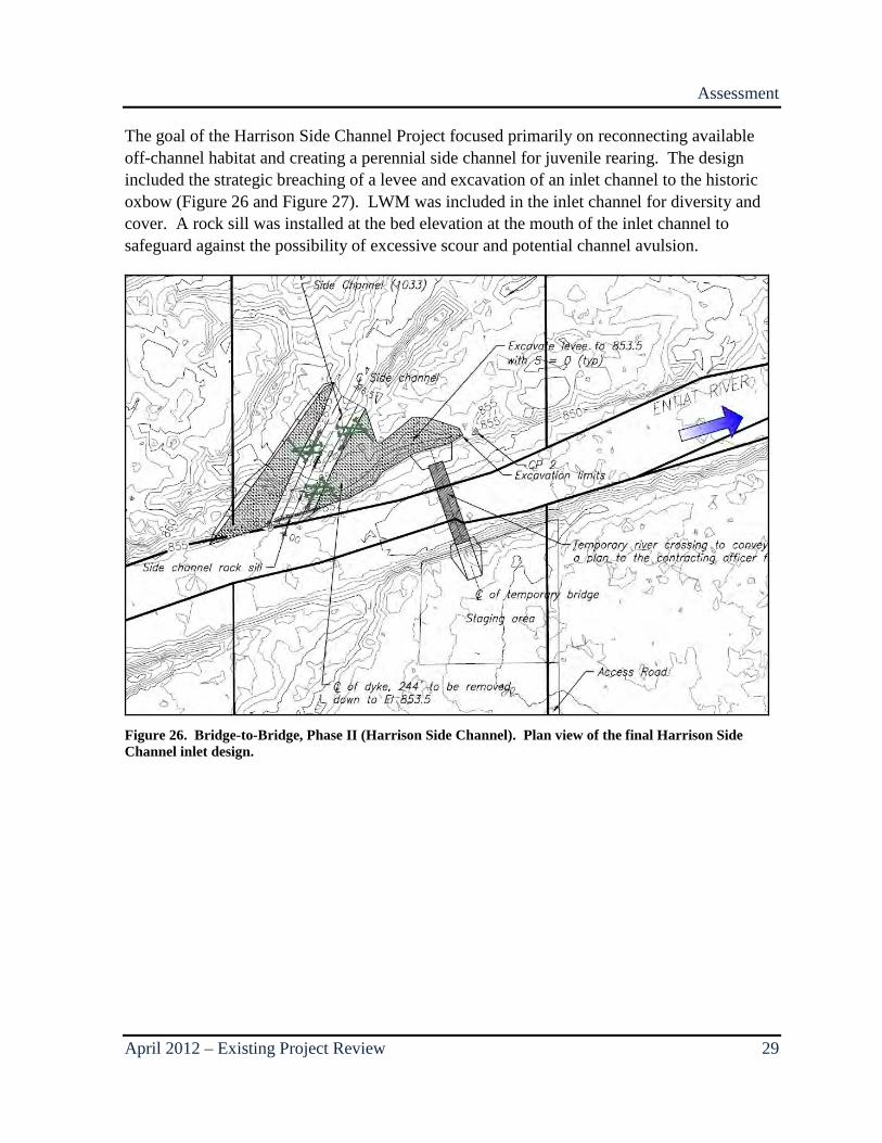
The goal of the Harrison Side Channel Project focused primarily on reconnecting available off-channel habitat and creating a perennial side channel for juvenile rearing. The design included the strategic breaching of a levee and excavation of an inlet channel to the historic oxbow (Figure 26 and Figure 27). LWM was included in the inlet channel for diversity and cover. A rock sill was installed at the bed elevation at the mouth of the inlet channel to safeguard against the possibility of excessive scour and potential channel avulsion.
Figure 26. Bridge-to-Bridge, Phase II (Harrison Side Channel). Plan view of the final Harrison Side Channel inlet design.
Assessment
30 Existing Project Review – April 2012
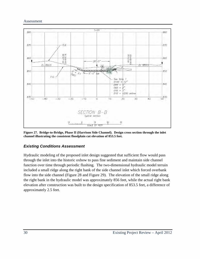
Figure 27. Bridge-to-Bridge, Phase II (Harrison Side Channel). Design cross section through the inlet channel illustrating the consistent floodplain cut elevation of 853.5 feet.
Existing Conditions Assessment
Hydraulic modeling of the proposed inlet design suggested that sufficient flow would pass through the inlet into the historic oxbow to pass fine sediment and maintain side channel function over time through periodic flushing. The two-dimensional hydraulic model terrain included a small ridge along the right bank of the side channel inlet which forced overbank flow into the side channel (Figure 28 and Figure 29). The elevation of the small ridge along the right bank in the hydraulic model was approximately 856 feet, while the actual right bank elevation after construction was built to the design specification of 853.5 feet, a difference of approximately 2.5 feet.

Assessment
April 2012 – Existing Project Review 31
Figure 28. Bridge-to-Bridge, Phase II (Harrison Side Channel). LiDAR view of project area.
Figure 29. Bridge-to-Bridge, Phase II (Harrison Side Channel). Two-dimensional modeling results illustrating proposed side channel inlet topography and velocity vectors calculated from a 2-year flood.
Assessment
32 Existing Project Review – April 2012
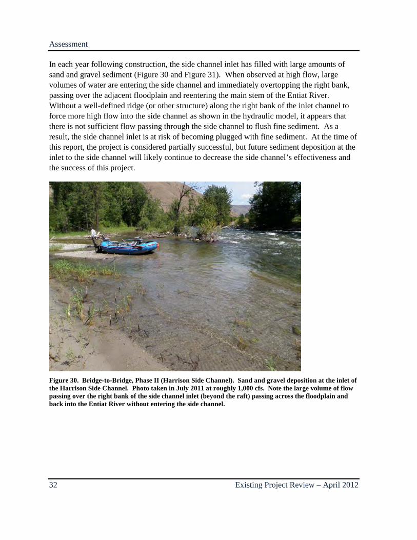
In each year following construction, the side channel inlet has filled with large amounts of sand and gravel sediment (Figure 30 and Figure 31). When observed at high flow, large volumes of water are entering the side channel and immediately overtopping the right bank, passing over the adjacent floodplain and reentering the main stem of the Entiat River. Without a well-defined ridge (or other structure) along the right bank of the inlet channel to force more high flow into the side channel as shown in the hydraulic model, it appears that there is not sufficient flow passing through the side channel to flush fine sediment. As a result, the side channel inlet is at risk of becoming plugged with fine sediment. At the time of this report, the project is considered partially successful, but future sediment deposition at the inlet to the side channel will likely continue to decrease the side channel’s effectiveness and the success of this project.
Figure 30. Bridge-to-Bridge, Phase II (Harrison Side Channel). Sand and gravel deposition at the inlet of the Harrison Side Channel. Photo taken in July 2011 at roughly 1,000 cfs. Note the large volume of flow passing over the right bank of the side channel inlet (beyond the raft) passing across the floodplain and back into the Entiat River without entering the side channel.
Assessment
April 2012 – Existing Project Review 33
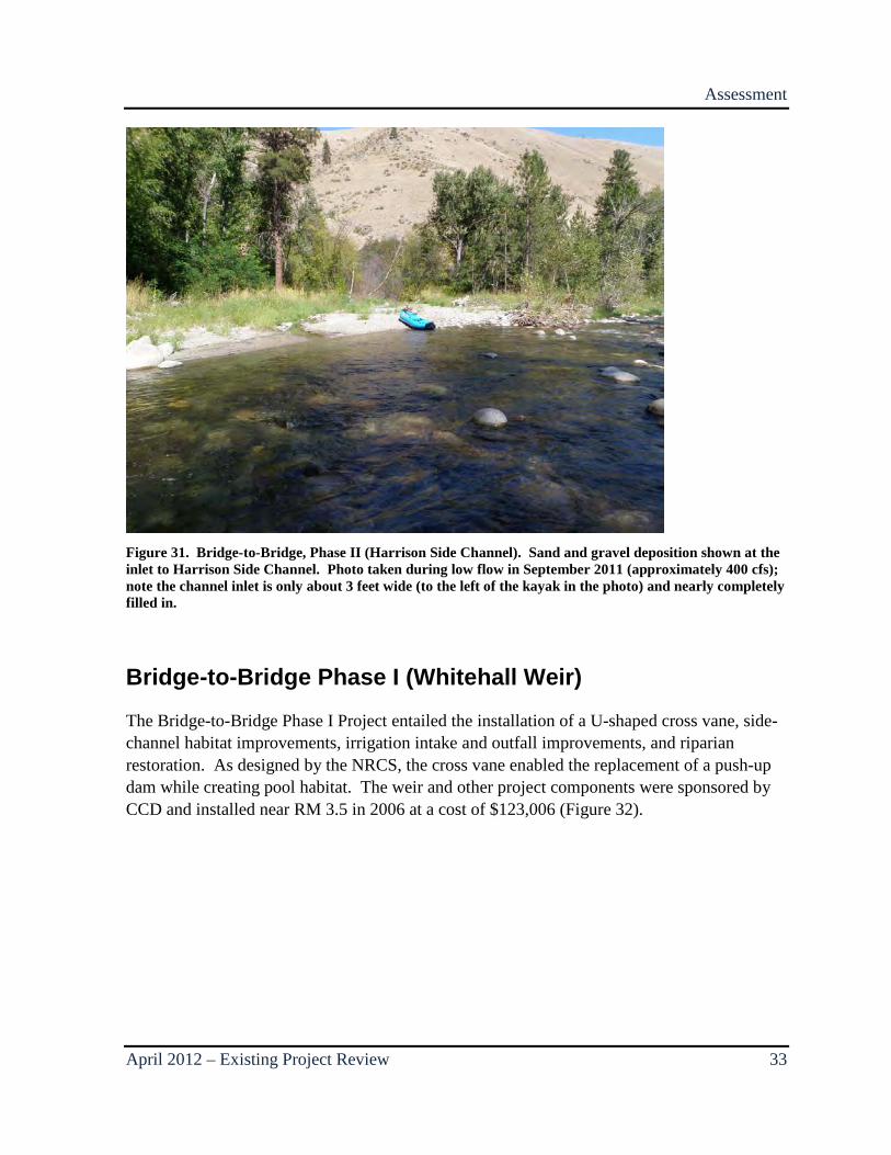
Figure 31. Bridge-to-Bridge, Phase II (Harrison Side Channel). Sand and gravel deposition shown at the inlet to Harrison Side Channel. Photo taken during low flow in September 2011 (approximately 400 cfs); note the channel inlet is only about 3 feet wide (to the left of the kayak in the photo) and nearly completely filled in.
Bridge-to-Bridge Phase I (Whitehall Weir)
The Bridge-to-Bridge Phase I Project entailed the installation of a U-shaped cross vane, side-channel habitat improvements, irrigation intake and outfall improvements, and riparian restoration. As designed by the NRCS, the cross vane enabled the replacement of a push-up dam while creating pool habitat. The weir and other project components were sponsored by CCD and installed near RM 3.5 in 2006 at a cost of $123,006 (Figure 32).

Assessment
34 Existing Project Review – April 2012
Figure 32. Bridge-to-Bridge Phase I (Whitehall Weir) site map.
Background
The U-shaped cross vane was designed with a deflection angle of 22° and both right and left vanes with a slope of 4.44 percent. This represents a slightly narrower vane without the cross-bar A-shape like the Dinkleman weir, while the other design elements were very similar. Project goals for the weir included establishment of a large pool incorporating LWM for cover and complexity. During construction, eight root wads were anchored to the river bed below either arm of the U-shaped cross vane and a pool was excavated immediately downstream of the weir (Figure 33). The design intent was to create a pool with a maximum bankfull depth of 8 feet (4 feet deeper than the surrounding bed) centered approximately between the downstream end of the weir arms (Figure 34), but according to personal communication with NRCS, the completed pool was excavated deeper than designed at the upstream end and shallower than designed at the downstream end (Figure 35).
Assessment
April 2012 – Existing Project Review 35
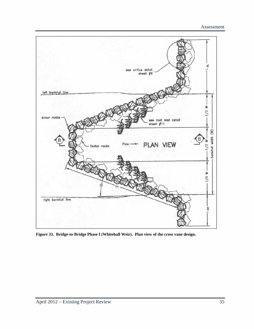
Figure 33. Bridge-to-Bridge Phase I (Whitehall Weir). Plan view of the cross vane design.

Assessment
36 Existing Project Review – April 2012
Figure 34. Bridge-to-Bridge Phase I (Whitehall Weir). Profile view of the cross vane design illustrating the location and shape of the proposed pool.
Figure 35. Bridge-to-Bridge Phase I (Whitehall Weir). Photo taken shortly after construction in 2006 looking across the weir from the right bank.
The left arm of the cross vane served to direct flow into the irrigation diversion through an orifice adjacent the left bank. A log boom, consisting of several logs attached together end-to-end with cable spanning the inlet of the diversion several dozen feet upstream from the diversion orifice, was constructed to aid the prevention of woody debris plugging the orifice.
Assessment
April 2012 – Existing Project Review 37
In addition to mainstem habitat, constructing a permanent diversion structure enabled the diversion channel to provide perennial off-channel habitat primarily for juvenile rearing and possibly adult spawning. Several boulders and two LWM structures were constructed in the diversion channel to promote habitat and hydraulic complexity. A flow dissipation structure was also installed at the outflow of the diversion channel to assist with fish passage.
Existing Conditions Assessment
Over the past several years, none of the rocks composing the weir appear to have moved significantly, but the pool has partially filled with coarse bedload (Figure 36). Deposition in the pool is likely the result of construction practices. Sediment excavated during construction was placed immediately upstream of the structure. This sediment over-steepened the drop across the weir and was likely mobilized and deposited in the pool immediately downstream.
Several root wads have also been removed by high flows. In their current location, the root wads inhibit plunge scour below the arms of the weir and each root wad is at risk of becoming dislodged by the high velocity flows. The log boom upstream of the diversion inlet captures some floating LWM, but NRCS stated that woody debris occasionally plugs the diversion orifice (NRCS 2011). Despite the LWM maintenance issue, the diversion channel is functioning very well, providing off-channel habitat with slower velocity flow and increased hydraulic diversity. The dissipation structure at the diversion outflow is intact and dissipating flow, but the plunge into the structure appears to be an upstream passage barrier based on an estimated drop height exceeding 0.8 foot.
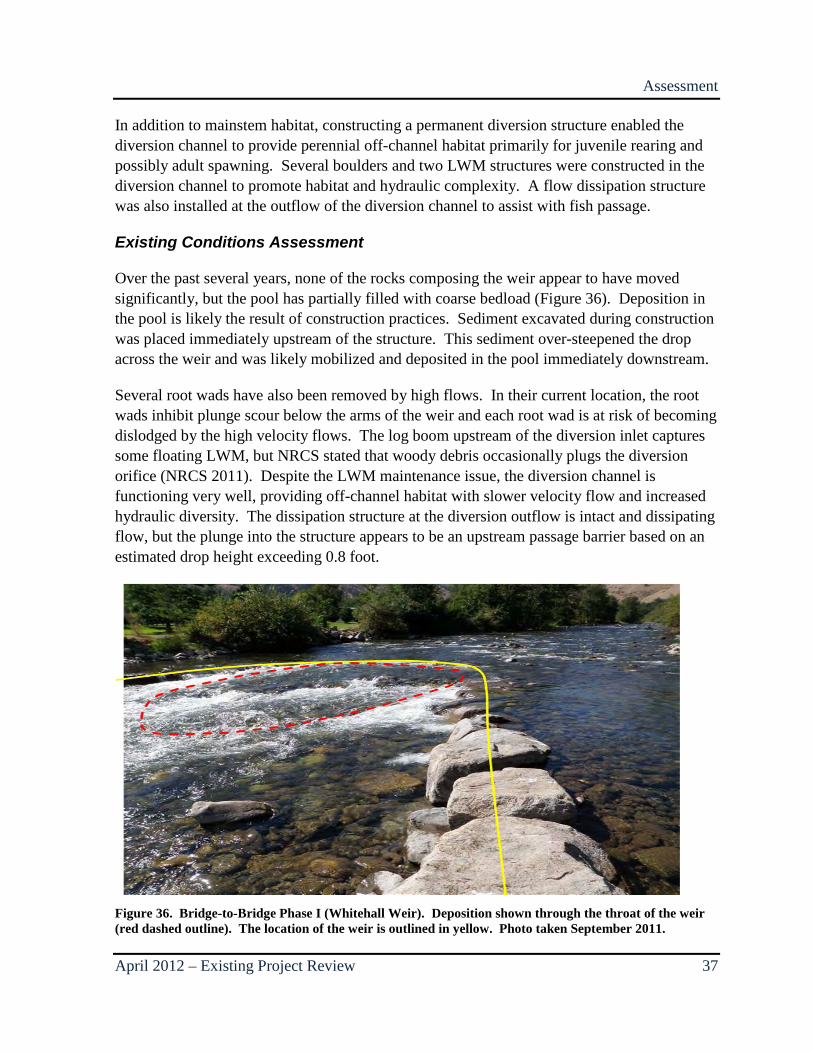
Figure 36. Bridge-to-Bridge Phase I (Whitehall Weir). Deposition shown through the throat of the weir (red dashed outline). The location of the weir is outlined in yellow. Photo taken September 2011.

Assessment
38 Existing Project Review – April 2012
Fire Station Weirs
In conjunction with Dinkleman Weir at RM 4.6, the NRCS designed and built two cross vanes between RM 3.1 and 3.2 as part of a demonstration project in 2001 (Figure 37). The purpose of the weirs was to create and maintain large mainstem pools. A secondary goal for the demonstration project was to determine if there was a break point at which the movement of individual rocks comprising the structure would jeopardize the structure as a whole.
Figure 37. Fire Station Weirs site map.
Background
The project site represents one of two habitat improvement demonstration locations selected based on landowner willingness and good line-of-sight access for observation and public viewing. Each of the cross vanes constructed as part of this demonstration project were designed and constructed using slightly different criteria to test which configuration best achieved the project goal of producing pool habitat. The upstream structure was designed as a
Assessment
April 2012 – Existing Project Review 39
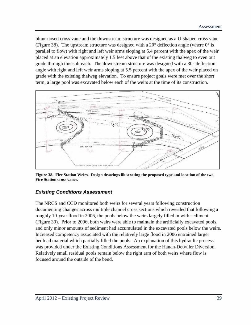
blunt-nosed cross vane and the downstream structure was designed as a U-shaped cross vane (Figure 38). The upstream structure was designed with a 20° deflection angle (where 0° is parallel to flow) with right and left weir arms sloping at 6.4 percent with the apex of the weir placed at an elevation approximately 1.5 feet above that of the existing thalweg to even out grade through this subreach. The downstream structure was designed with a 30° deflection angle with right and left weir arms sloping at 5.5 percent with the apex of the weir placed on grade with the existing thalweg elevation. To ensure project goals were met over the short term, a large pool was excavated below each of the weirs at the time of its construction.
Figure 38. Fire Station Weirs. Design drawings illustrating the proposed type and location of the two Fire Station cross vanes.
Existing Conditions Assessment
The NRCS and CCD monitored both weirs for several years following construction documenting changes across multiple channel cross sections which revealed that following a roughly 10-year flood in 2006, the pools below the weirs largely filled in with sediment (Figure 39). Prior to 2006, both weirs were able to maintain the artificially excavated pools, and only minor amounts of sediment had accumulated in the excavated pools below the weirs. Increased competency associated with the relatively large flood in 2006 entrained larger bedload material which partially filled the pools. An explanation of this hydraulic process was provided under the Existing Conditions Assessment for the Hanan-Detwiler Diversion. Relatively small residual pools remain below the right arm of both weirs where flow is focused around the outside of the bend.
Assessment
40 Existing Project Review – April 2012
Figure 39. Fire Station Weirs. NRCS monitoring results from the upper weir illustrating pre-construction conditions (March 14, 2000), as built conditions (October 3, 2001) and conditions from six subsequent measurements taken over the next 10 years. It can be seen that the excavated pool below the cross vane has filled with sediment approaching the preconstruction conditions.
In addition to the excavated pools partially filling with sediment and possibly exacerbating the condition, several of the boulders comprising both weirs have moved (Figure 40 and Figure 41). An assessment of both weirs was completed by Reclamation in 2006 following the large flood which documented the movement of several footer and header rocks. In every instance, weir rock movement was attributed to slumping and/or rolling of the footer rocks associated with poor construction methods or scour and undercutting. During the field reconnaissance in 2011, it did not appear that any additional rocks had moved since 2006.
Assessment
April 2012 – Existing Project Review 41
Figure 40. Fire Station Weirs. Photo of upper Fire Station weir taken September 2011 at low flow (about 400 cfs), illustrating where two header rocks were moved out of the weir. Several header and footer rocks were moved from this weir by high flows.
Figure 41. Fire Station Weirs. Lower weir where several rocks were moved by high flows. Photo taken in September 2011.

Assessment
42 Existing Project Review – April 2012
The four LWM elements installed adjacent the weirs were also observed during the field reconnaissance in 2011. All four of the LWM structures had been partially buried by gravel deposition resulting largely from their location within the relatively slow-velocity water of the eddy that forms below the arms of the weirs (Figure 42). As a result of this deposition, the relatively small LWM structures may not be providing the desired level of cover intended by the design.
Figure 42. Fire Station Weirs. Photo taken at low water in 2006 illustrating gravel deposition on the left bank in the lee of the lower weir partially burying the LWM structure in this location. The top of the root wad can be seen on the left side of the photo.
Although the Fire Station weirs and the Dinkleman weir are not currently meeting all of their design objectives, they continue to provide hydraulic diversity and complexity in an otherwise relatively homogenous reach.
Milne
The Milne project consists of multiple instream habitat structures near RM 2.9 including five rock barbs, one diversion barb structure with sluice-gate, four root wad structures, and six boulder clusters with five boulders each (Figure 43). The purpose of the project was to improve habitat complexity by increasing instream structure and diversity. Designs were completed by Reclamation and the project was implemented by Chelan County in 2006 at a cost of $97,000.
Assessment
April 2012 – Existing Project Review 43
Figure 43. Milne site map.
Background
As with many other subreaches of the lower Entiat, the Milne subreach is straight, armored, and confined. Within this reach, the bankfull channel area and 2-year flood area are essentially the same; therefore, frequent high flows do not have the ability to dissipate energy across an active floodplain. The goal of the Milne project was to install habitat structures that would increase complexity and diversity at high and low flows. A secondary goal included improvements to an irrigation diversion which had previously consisted of a push-up wing dam that required frequent maintenance. This wing dam was replaced with a much more robust rock barb which included a sluice gate (Figure 44). The combination of a rock barb constructed with very large boulders and the addition of a sluice gate to help manage fine sediment was intended to reduce maintenance needs and the associated disruption to the stream bed.
Several different structure types were installed, in part as an experiment to monitor which types better achieved the project goals. Rock barbs include low-height barbs, which roughly
Assessment
44 Existing Project Review – April 2012
follow the bank contour as they extend out into the channel, and bankfull barbs which extend into the channel at bankfull elevation before sloping toward the bed (Figure 45 and Figure 46). Boulder clusters were placed in various orientations based on field conditions, but all boulder clusters were installed with spaces between the boulders and such that the structures are overtopped by modest flows (roughly 1,000 cfs or less) (Figure 47). Root wad structures were designed using two logs with root wads attached, forming a triangle with the upstream log overlapping the downstream log (Figure 48).
Figure 44. Milne. Rock barb detail copied from the design drawings.
Assessment
April 2012 – Existing Project Review 45
Figure 45. Milne. Low-height rock barb detail which roughly follows the contour of the bank.
Figure 46. Milne. Bank-height rock barb with extends out from the bank at the bankfull elevation before sloping down toward the bed.

Assessment
46 Existing Project Review – April 2012
Figure 47. Milne. Boulder cluster looking downstream at low-water. Photo taken in August of 2009.
Figure 48. Milne. Pair of root wad structures (each structure consists of two overlapping logs with root wads). In every instance, the upstream log was installed overlapping the downstream log.
Assessment
April 2012 – Existing Project Review 47
Existing Conditions Assessment
None of the structures installed as part of the Milne Project have been significantly damaged or reworked by the river since their installation in 2006, during which time the largest flood was measured at 3,610 cfs in June 2007, roughly equal to a 2-year event. Minor erosion was observed at the point where the diversion barb ties into the bank. At this location, the heavily armored barb joins the relatively unarmored bank. When the barb is overtopped, erosion of the bank occurs. As vegetation continues to establish in this area, the potential for future erosion will be reduced.
It appears that all of the other rock barbs were installed following the low-height barb design. These structures do not intercept as much flow as the larger bank-height barbs and have less hydraulic effect. None of the rock barbs obstruct enough of the hydraulic radius of the channel to force enough flow convergence to scour a large pool into the heavily armored bed (Figure 49). Similar to the cross vanes, the hydraulic effect of the barbs is insufficient to mobilize the armored bed at flows below the threshold condition in this subreach, and a pool will not form nor will an excavated pool be maintained. Despite this, all of the barbs create relatively slow-water eddies along the banks which increases both hydraulic diversity and instream complexity.
Figure 49. Milne. Photo shows a rock barb that does not occupy a large portion of the channel’s hydraulic radius (not very tall and does not extend into channel very far). No scour pool has formed at the point of the barb. The photo was taken at low flow, looking upstream in September 2010.
Assessment
48 Existing Project Review – April 2012
The root wad structures are performing relatively well. Each structure provides cover and hydraulic diversity, and several of the structures have maintained a pool beneath the pair of root wads at the apex of the structure (Figure 50 and Figure 51). The pools were initially excavated by machinery during the installation of the structures. It is unclear if the pools will be maintained in the long term since there has not been a large flood that would mobilize the armored bed since the installation of these structures, but they are currently meeting design objectives and providing more complexity and hydraulic diversity than the rock barbs. All of the root wad structures were built with the upstream log overlapping the downstream log, which may increase the potential for bank erosion below the structure as water spilling over the top log is directed toward the bank. During field reconnaissance in 2011, no significant bank erosion was observed below the log structures, and as vegetation continues to become established, bank erosion potential will decrease. Similar to the rock barbs, these root wad structures are relatively small and are effective at lower flows, but will likely produce minimal or negligible hydraulic effect during large floods.
Figure 50. Milne. Single 2-log rootwad structure along the right bank (photo taken September 2011 at about 1,000 cfs).
Assessment
April 2012 – Existing Project Review 49
Figure 51. Milne. Photo of double root wad log structure showing the pool maintained at apex of root wads. Photo was taken at low flow in September 2010.
The boulder clusters were built with large gaps between the rocks, and all of the structures are overtopped at relatively modest flows (roughly less than 1000 cfs) (Figure 52). As a result of the frequent overtopping and gaps between boulders, little or no gravel deposition was observed behind the boulder clusters. At low flows, the structures provide hydraulic refuge and diversity, but at high flows, the effect is overwhelmed by plunging flow overtopping the boulders.
Assessment
50 Existing Project Review – April 2012
Figure 52. Milne. Photo looking downstream at two boulder clusters taken at low flow in September 2010.
Yakama Tribe Engineered Logjam
The Yakama Tribe sponsored the design and construction of an engineered log jam (ELJ) on the outside of a bend on river left near RM 2.5 in the lower Entiat River for the purpose of habitat diversity, pool formation, and cover (Figure 53). Interfluve, Inc. designed the project which was constructed in 2010 at a cost of $88,000.
Assessment
April 2012 – Existing Project Review 51
Figure 53. Yakama Tribe ELJ site map.
Background
First conceived as a much larger project that included multiple structures, the concept for this project went through several iterations before the final design. Despite changes to the scope of the project, its goals have always included increased complexity. Specific goals for the final design ELJ include increased instream diversity, better cover, and development of a scour pool.
The completed ELJ is essentially a gravity structure anchored by earthen backfill and boulder ballast consisting of several pairs of cabled boulders (Figure 54). River safety was taken into consideration with the design, limiting the lateral extent of the structure and excluding the use of any “strainer” logs or root wads that extend into the thalweg (Figure 55). A small pool was excavated adjacent to the structure during construction with the intent that the structure’s hydraulic influence will maintain the pool over time. Disturbed surfaces surrounding the ELJ were also planted with live stakes of willow and other native species.
Assessment
52 Existing Project Review – April 2012
Figure 54. Yakama Tribe ELJ. Detail of the final ELJ design.
Figure 55. Yakama Tribe ELJ. Photo looking upstream at the completed ELJ.
Assessment
April 2012 – Existing Project Review 53
Existing Conditions Assessment
The ELJ appears to be constructed as designed and is functioning as anticipated both hydraulically and from a river safety perspective. At the time of this assessment, the completed ELJ has gone through one high flow season and is thus far successfully maintaining a pool along its face 2 to 3 feet deeper than the surrounding bed elevation. The structure’s location along the outside of a bend utilizes the natural flow convergence and helical flow associated with bends to increase scour potential. Unlike low-profile cross vanes, an ELJ such as this one is relatively tall and located along the outside of a bend where its hydraulic effect will increase as discharge goes up Sediment transport thresholds are expected to be overcome during episodic large floods such that the armored bed becomes mobilized, but local hydraulic effects provided by this ELJ are anticipated to maintain the residual pool at this location unlike lower-profile structures. Future monitoring following a threshold event capable of mobilizing the armored bed will be necessary to substantiate this claim.
Below the Bridge (Moody Canyon)
The Below the Bridge Project refers to several instream rock and log habitat structures, and improvements to an irrigation diversion near RM 1.4 immediately below the Keystone Bridge. Project goals were centered on improved habitat complexity and reduction of instream disturbance associated with an existing irrigation diversion (Figure 56). The project was designed by Anchor QEA based on conceptual plans developed by Reclamation. CCD sponsored project implementation which occurred in 2009 at a cost of $594,275.
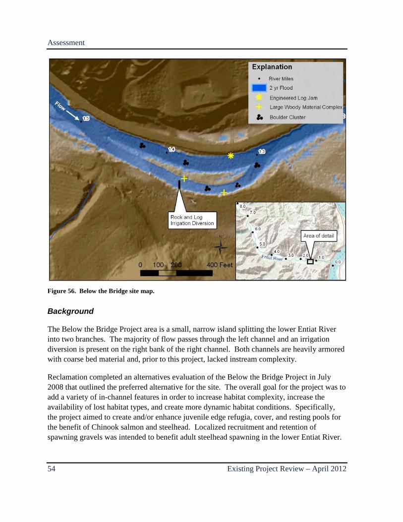
Assessment
54 Existing Project Review – April 2012
Figure 56. Below the Bridge site map.
Background
The Below the Bridge Project area is a small, narrow island splitting the lower Entiat River into two branches. The majority of flow passes through the left channel and an irrigation diversion is present on the right bank of the right channel. Both channels are heavily armored with coarse bed material and, prior to this project, lacked instream complexity.
Reclamation completed an alternatives evaluation of the Below the Bridge Project in July 2008 that outlined the preferred alternative for the site. The overall goal for the project was to add a variety of in-channel features in order to increase habitat complexity, increase the availability of lost habitat types, and create more dynamic habitat conditions. Specifically, the project aimed to create and/or enhance juvenile edge refugia, cover, and resting pools for the benefit of Chinook salmon and steelhead. Localized recruitment and retention of spawning gravels was intended to benefit adult steelhead spawning in the lower Entiat River.
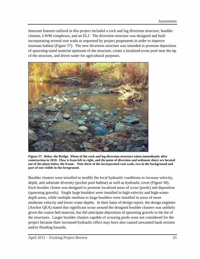
Assessment
April 2012 – Existing Project Review 55
Instream features utilized in this project included a rock and log diversion structure, boulder clusters, LWM complexes, and an ELJ. The diversion structure was designed and built incorporating several root wads as requested by project proponents in order to improve instream habitat (Figure 57). The new diversion structure was intended to promote deposition of spawning-sized material upstream of the structure, create a localized scour pool near the tip of the structure, and divert water for agricultural purposes.
Figure 57. Below the Bridge. Photo of the rock and log diversion structure taken immediately after construction in 2010. Flow is from left to right, and the point of diversion and sediment sluice are located out of the photo below the frame. Note three of the incorporated root wads, two in the background and part of one visible in the foreground.
Boulder clusters were installed to modify the local hydraulic conditions to increase velocity, depth, and substrate diversity (pocket pool habitat) as well as hydraulic cover (Figure 58). Each boulder cluster was designed to promote localized areas of scour (pools) and deposition (spawning gravels). Single large boulders were installed in high-velocity and high-water-depth areas, while multiple medium to large boulders were installed in areas of more moderate velocity and lower water depths. In their basis of design report, the design engineer (Anchor QEA) stated that significant scour around the designed boulder clusters was unlikely given the coarse bed material, but did anticipate deposition of spawning gravels in the lee of the structures. Larger boulder clusters capable of scouring pools were not considered for the project because their increased hydraulic effect may have also caused unwanted bank erosion and/or flooding hazards.

Assessment
56 Existing Project Review – April 2012
Figure 58. Below the Bridge. Photo of a single large boulder with two smaller flanking boulders comprising a single cluster taken at about 1,000 cfs in July 2011. Flow is from left to right. Based on estimates from field observations during high flow, this particular structure is overtopped at flows above approximately 2,500 cfs. Note the relatively large area of slow-velocity water in the lee of the structure.
LWM complexes and the ELJ were built to promote deposition of spawning gravel in the velocity shadow behind the structures, promote local scour near the apex of the structures, dissipate energy, and provide cover and refuge for juvenile fish. Specifically, the LWM complexes were built to not be frequently over-topped, thereby imparting greater influence on local hydraulics and maintaining a velocity shadow downstream of the structure for most high flow events (Figure 59). The ELJ is essentially a large LWM complex intended to impart greater influence on local hydraulics (Figure 60 and Figure 61). Its hydraulic impact was reduced when the size of the ELJ was scaled back due to landowner concerns partially related to the potential for significant ice accumulation and associated flooding. Originally the ELJ was planned to extend 10 to 20 feet further in the channel than was constructed. All of the wood structures were designed with an increased factor of safety to accommodate the potential occurrence of ice dams, ice accumulation, and ice impact forces.
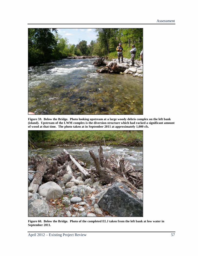
Assessment
April 2012 – Existing Project Review 57
Figure 59. Below the Bridge. Photo looking upstream at a large woody debris complex on the left bank (island). Upstream of the LWM complex is the diversion structure which had racked a significant amount of wood at that time. The photo taken at in September 2011 at approximately 1,000 cfs.
Figure 60. Below the Bridge. Photo of the completed ELJ taken from the left bank at low water in September 2011.
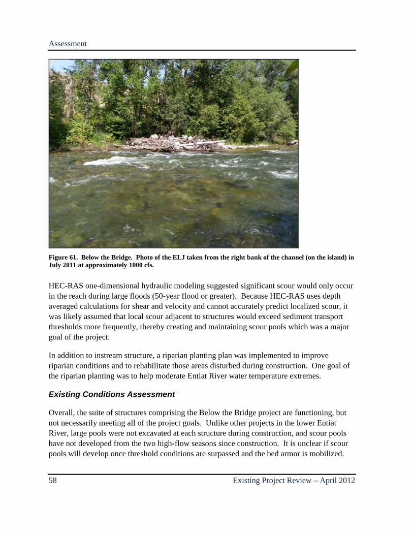
Assessment
58 Existing Project Review – April 2012
Figure 61. Below the Bridge. Photo of the ELJ taken from the right bank of the channel (on the island) in July 2011 at approximately 1000 cfs.
HEC-RAS one-dimensional hydraulic modeling suggested significant scour would only occur in the reach during large floods (50-year flood or greater). Because HEC-RAS uses depth averaged calculations for shear and velocity and cannot accurately predict localized scour, it was likely assumed that local scour adjacent to structures would exceed sediment transport thresholds more frequently, thereby creating and maintaining scour pools which was a major goal of the project.
In addition to instream structure, a riparian planting plan was implemented to improve riparian conditions and to rehabilitate those areas disturbed during construction. One goal of the riparian planting was to help moderate Entiat River water temperature extremes.
Existing Conditions Assessment
Overall, the suite of structures comprising the Below the Bridge project are functioning, but not necessarily meeting all of the project goals. Unlike other projects in the lower Entiat River, large pools were not excavated at each structure during construction, and scour pools have not developed from the two high-flow seasons since construction. It is unclear if scour pools will develop once threshold conditions are surpassed and the bed armor is mobilized.

Assessment
April 2012 – Existing Project Review 59
As with other projects in the lower Entiat River, the larger structures that obstruct a larger portion of the river’s hydraulic radius tend to have a greater hydraulic impact and generate the greatest scour potential. To meet design criteria for potential ice loading, each of the LWM structures was backfilled with large volumes of boulders for added ballast which now occupies much of the interstitial space between the logs. While this improves the structural integrity of the structures, it also detracts from its ability to provide cover for juvenile fish.
As predicted by the HEC-RAS model, it is unlikely that the boulder clusters will ever create scour pools, but they are creating velocity breaks in the channel. The larger (taller) boulder clusters in particular are also sorting small pockets of gravel-sized sediment. Field observations suggest that structures not frequently overtopped sort and accumulate more gravel-sized sediment than those that are frequently overtopped.
In the first 2 years following construction, the diversion structure racked a significant amount of LWM which all but blocked the right channel (Figure 62). Two or three large pieces of LWM hung up on the root wads and were incorporated into the diversion structure, which then racked many more relatively smaller pieces. It is unclear if woody debris would have racked on the structure even without the built in root wads, but certainly the root wads exacerbated the problem. During high flows in 2011, so much of the right channel was obstructed by debris that water began to overtop the island, threatening an avulsion, and debris plugged the inlet to the irrigation ditch. As a result, the excess racked material was cleared from the diversion once flows lowered to the point where it was safe and the incorporated root wads were trimmed to reduce future racking potential (Figure 63).
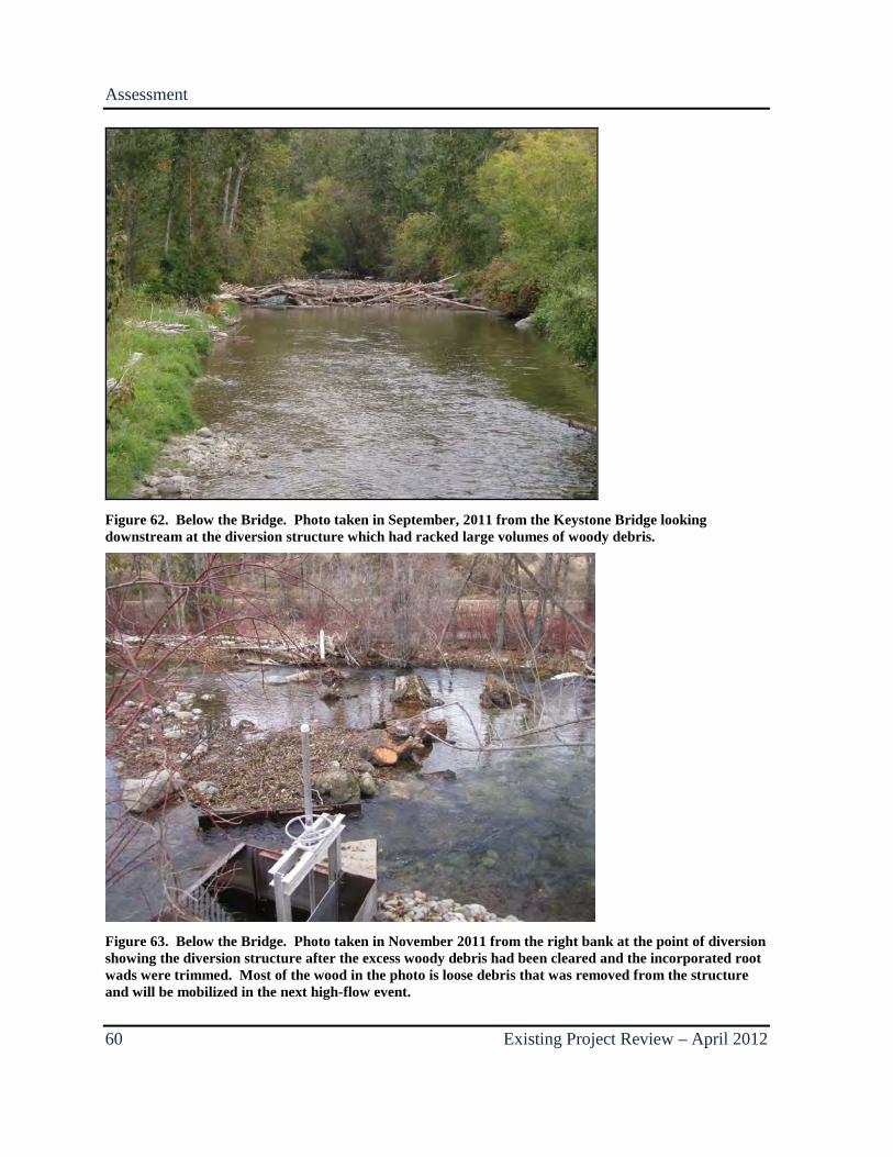
Assessment
60 Existing Project Review – April 2012
Figure 62. Below the Bridge. Photo taken in September, 2011 from the Keystone Bridge looking downstream at the diversion structure which had racked large volumes of woody debris.
Figure 63. Below the Bridge. Photo taken in November 2011 from the right bank at the point of diversion showing the diversion structure after the excess woody debris had been cleared and the incorporated root wads were trimmed. Most of the wood in the photo is loose debris that was removed from the structure and will be mobilized in the next high-flow event.

Assessment
April 2012 – Existing Project Review 61
Gravel deposition upstream of the diversion was one of the goals of the preferred alternative chosen for design, but very little gravel deposition has taken place. Without exceeding threshold conditions required to mobilize the bed armor in the lower Entiat River, the sediment transported by the river consists primarily of sand and gravel. During the spring of 2011, the Entiat River maintained a roughly 1.5-year flood level for nearly 30 days. During that time, the right channel was severely obstructed with LWM as it was in 2010, and presumably the suspended sediment load consisted primarily of sand and gravel. Despite these ideal conditions for gravel deposition, field observations and preliminary survey results suggest that very little to no gravel deposition occurred upstream of the diversion.
It is yet to be seen how much deposition will result from the diversion during a large flood that exceeds threshold conditions mobilizing the bed. Because the diversion structure spans nearly the entire width of the side channel, it essentially acts as a grade control riffle in the right channel. During a large flood, sufficient bedload could potentially fill the right channel to the elevation of the top of the diversion structure which is 2 to 4 feet higher than the bed elevation immediately upstream of the structure. Filling the side channel with such a large volume of sediment may result in disruption of the diversion supply, bank erosion or avulsion through the island, or the complete abandonment of the side channel. As specified in the preferred alternative, the goal of deposition upstream of the diversion structure may need to be revisited.
Summary
62 Existing Project Review – April 2012
3.0 SUMMARY
Several instream habitat improvement projects have been completed in the lower 7 miles of the Entiat River over the past decade. Most are functioning reasonably well and meeting the majority of their individual design objectives, but some are not. Most of the structures that are no longer meeting their primary design objectives were constructed before the 2006 high-water season which was a 10-year flood. Subsequent floods have not exceeded a 2-year event; therefore, projects constructed following the high flow season of 2006 have not been subject to such an event. The lower Entiat River is a threshold channel, meaning channel-forming processes such as mobilization of the bed armor do not occur until a certain threshold has been overcome. The threshold condition may vary slightly between sites, but is defined by the discharge required to mobilize the bed at that location. Based on the number of excavated pools that filled with coarse sediment in 2006, it is estimated that threshold conditions were surpassed in many locations during the May 2006 flood event which reached a peak discharge of 4,780 cfs. When the threshold is passed, the streambed becomes mobilized, resulting in live-bed conditions which affect channel processes (such as scour) differently than clear-water conditions. Under live-bed conditions, scour holes created during the rising stage of a flood often refill during the recession stage, which appears to have occurred in 2006.
In general, as a result of the armored bed conditions and the large flood threshold required to mobilize bed material, larger instream structures that obstruct more flow tend to have a greater hydraulic impact and are more capable of maintaining scour pools and other hydraulic features than smaller structures that obstruct less flow. For example, large ELJs tend to create and maintain scour pools better than low-profile cross vanes. During minor floods that do not exceed threshold conditions, the armored bed material does not mobilize, but the channel continues to transport large volumes of suspended load consisting of gravel, sand, and silt. Gravel deposition behind large boulder clusters has been shown to be effective, while sand deposition in side channels has been problematic.
With climate change models predicting larger peak floods and smaller low-water discharges, trends in sediment transport may change in the future. More frequent high-discharge floods will increase the likelihood that threshold conditions are surpassed and the armored bed material will mobilize more frequently. Ongoing monitoring and surveys will help to verify changing conditions, further inform practitioners of successful project types, and generally support the advancement of habitat improvement efforts.

Summary
April 2012 – Existing Project Review 63
At this time Reclamation plans to develop adaptive management options/alternatives for projects in the lower Entiat River utilizing some of the information that has been gleaned from this and other post-construction monitoring efforts. Alternative Evaluation reports for any planned adaptive management projects, as well as completion reports for those projects that are implemented, will provide additional information and data for future monitoring efforts within the lower Entiat River.
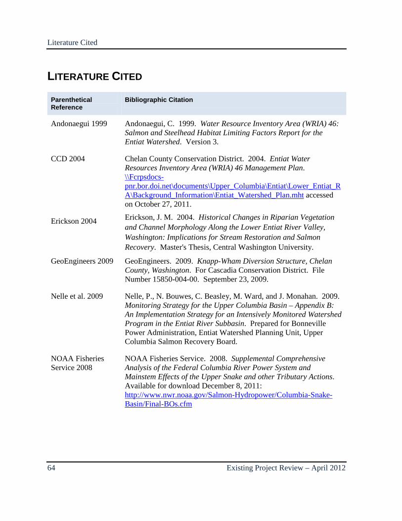
Literature Cited
64 Existing Project Review – April 2012
LITERATURE CITED
Parenthetical Reference
Bibliographic Citation
Andonaegui 1999 Andonaegui, C. 1999. Water Resource Inventory Area (WRIA) 46: Salmon and Steelhead Habitat Limiting Factors Report for the Entiat Watershed. Version 3.
CCD 2004 Chelan County Conservation District. 2004. Entiat Water Resources Inventory Area (WRIA) 46 Management Plan. \\Fcrpsdocs-pnr.bor.doi.net\documents\Upper_Columbia\Entiat\Lower_Entiat_RA\Background_Information\Entiat_Watershed_Plan.mht accessed on October 27, 2011.
Erickson 2004 Erickson, J. M. 2004. Historical Changes in Riparian Vegetation and Channel Morphology Along the Lower Entiat River Valley, Washington: Implications for Stream Restoration and Salmon Recovery. Master's Thesis, Central Washington University.
GeoEngineers 2009 GeoEngineers. 2009. Knapp-Wham Diversion Structure, Chelan County, Washington. For Cascadia Conservation District. File Number 15850-004-00. September 23, 2009.
Nelle et al. 2009 Nelle, P., N. Bouwes, C. Beasley, M. Ward, and J. Monahan. 2009. Monitoring Strategy for the Upper Columbia Basin – Appendix B: An Implementation Strategy for an Intensively Monitored Watershed Program in the Entiat River Subbasin. Prepared for Bonneville Power Administration, Entiat Watershed Planning Unit, Upper Columbia Salmon Recovery Board.
NOAA Fisheries Service 2008
NOAA Fisheries Service. 2008. Supplemental Comprehensive Analysis of the Federal Columbia River Power System and Mainstem Effects of the Upper Snake and other Tributary Actions. Available for download December 8, 2011: http://www.nwr.noaa.gov/Salmon-Hydropower/Columbia-Snake-Basin/Final-BOs.cfm

Literature Cited
April 2012 – Existing Project Review 65
Parenthetical Reference
Bibliographic Citation
NOAA Fisheries Service 2010
National Marine Fisheries Service, Supplemental Consultation on Remand for Operation of the Federal Columbia River Power System, 11 Bureau of Reclamation Projects in the Columbia Basin and ESA Section 10(a)(1)(A) Permit for Juvenile Fish Transportation Program, May 20, 2010, F/NWR/2010/02096.
NRCS 2011 Joe Lange, P.E., Civil Engineer, Natural Resources Conservation Service, personal communication, need a date here
Reclamation 2009 Bureau of Reclamation. 2009. Entiat Tributary Assessment: Chelan County, Washington. U.S. Department of the Interior, Bureau of Reclamation, Technical Services Center, Denver, Colorado. January 2009. http://www.usbr.gov/pn/programs/fcrps/thp/ucao/entiat/tribassmt/index.html accessed on October 27, 2011.
Reclamation 2012 Bureau of Reclamation. 2009. Lower Entiat Reach Assessment: Chelan County, Washington. U.S. Department of the Interior, Bureau of Reclamation, Technical Services Center, Denver, Colorado. January 2012. http://www.usbr.gov/pn/programs/fcrps/thp/ucao/lowerentiat/finalRA.pdf accessed on February 6, 2012.