exergen infrared non-contact temperature sensors · 59 how the lo e filter reduces errors due to...
TRANSCRIPT

Exergen Infrared Non-Contact Temperature Sensors
Technote e-Book Print

The NetherlandsPastoor Clercxstraat 265465 RH Veghel Tel: Fax:
+31(0) 413 37 65 99+31(0) 413 37 93 10
USA400 Pleasant StreetWatertown, MA 02472Tel: Fax:
+1 617 649 6322+1 617 923 9911
Exergen Global offices:
Infrared Temperature Sensors1/82
Copyright © 2015 by Exergen Corporation, Watertown, MA 02472 USA.All rights reserved. No part of this publication may be reproduced in any material form without the written permission of the copyright holder(s) except in accordance with the express written permission of the authors and/or Copyright Holders as provided herein.
All requests for permissions or information regarding content should be directed to:
Exergen Corporation400 Pleasant StreetWatertown, MA 02472USA
TN-503-EN-V0
The NetherlandsPastoor Clercxstraat 265465 RH Veghel Tel: Fax:
+31(0) 413 37 65 99+31(0) 413 37 93 10
USA400 Pleasant StreetWatertown, MA 02472Tel: Fax:
+1 617 649 6322+1 617 923 9911
Exergen Global offices:
Infrared Temperature Sensors2/82
INFRARED TECHNOLOGY
A bit of historyIn 1665, Sir Isaac Newton became the first to slit sunlight into colors with a prism, thus demonstrating the existence of light as radiated energy of differing wavelengths. About 135 years later, another English astronomer/scientist, William Herschel, measured the heat content of each the colors of Newton’s spectrum. Herschel was shocked to discover that his thermometer registered the greatest heat beyond the red – in an area of the spectrum he could not see: a serendipitous result, as lore has it, of his thermometer rolling off the red area of the spectrum. He coined the term INFRARED to describe this heat energy, which was beyond the red. All objects emit infrared energy at temperatures above absolute zero (-273°C, -460°F).
Herschel demonstrated that infrared heat radiation and light are simply two forms of electromagnetic energy. Our eyes see light energy because we are equipped to see the wavelengths of light. We cannot see infrared because the wavelengths are too long for our eyes. The very first non contact thermometer was the human eye. An example of a special infrared sensing adaptation from the animal world is the pit viper, which can actually locate warm-blooded animals in the dark with its infrared sensing pit organs below its eyes. An infrared sensor, like Herschel’s thermometer and the viper’s pit organs, is slightly heated when viewing the longer wavelengths of infrared energy, and provides quantitative information regarding the source of energy.
At the turn of the twentieth century, the German physicist Max Planck discovered the correct mathematical formulation of the relationship between temperature and infrared radiation, for which he won the Nobel Prize, thus paving the way for its use as a method of measuring temperature WITHOUT CONTACT. An unanticipated result of Planck’s discovery was quantum physics, arguably the most important scientific development of this century. Then of course we have the unforgettable Albert Einstein who confirmed Planck’s Quanta by using the photoelectric effect although Einstein did not really like the result. Recent advances in the technology of infrared temperature measurement have stimulated development of devices that are without doubt, more sensitive than Herschel’s thermometer. Several applications of this technology have made it possible to design devices capable of making fast, accurate, and safe non-invasive measurement. In the eighties Dr. Frank Pompei started Exergen, a worldwide leader of unique, patented sensor technologies that set the benchmark for non-contact infrared temperature measurement throughout a wide range of medical and industrial applications such as digital printing, automotive, food, agriculture, aesthetical etc. He not only invented the world’s first infrared thermocouple, the world’s first pocket sized scanner and non invasive medical infrared thermometer, he also introduced the Speed Boost Equation. Dr. Pompei has filed over 75 patents and next to being the CEO of Exergen Corp, he is also a Guest Scholar at Harvard University.
In this e-book you will find a wide variety of tech notes, which we will keep on adding with every customized solution. You will be guided by our character... our vipIR. Why this vipIR? First of all it stands for very important product infrared. Of course the vipIR is a snake with a wink to the viper and in particular the pit viper which we mentioned a bit earlier. The pit viper’s organs are small facial cavities covered by a thin membrane of sensory cell that respond to temperature differences of just .003°C, and can detect the presence of a warm-blooded animal at distances of up to 50 cm in total darkness simply from the animal’s infrared radiation.
We do hope that this e-book will provide you with the information you are looking for. If not, check out our website www.exergenglobal.com or give us a call at +31413376599 or +16176496322.

Infrared Temperature Sensors3/82
TABLE OF CONTENTS
Technote Name Page1 Quick installation guide pre-calibrated models 52 IRt/c setup with auto-tune temperature controllers 63 IRt/c can be used with up to 1,000 feet (300 m) of thermocouple extension wire 74 IRt/c controls paint curing with radiant heaters 87 Temperature measurements in steaming environments 9
10 IRt/c’s are intrinsically safe when used with barriers 1014 Multiplexed datalogging applications 1115 Air purging is recommended when using water cooling 1216 Why offsets are caused by leakage currents 1318 Detecting hot melt adhesive in product assembly, packaging 1419 How the pit viper measures infrared radiation 1621 Controlling web roller temperature 1722 Controlling vacuum forming and thermoforming processes 1824 IRt/c controls product drying (paper, wood, textiles, film) 1926 IRt/c repeatability and long-term accuracy 2028 IRt/c trouble shooting guide 2129 IRt/c can measure obliquely 2230 IRt/c measures vibrating objects 2331 What is emissivity? 2432 Where is the emissivity adjustment? 2533 Why the d-series is recommended for IRt/c temperature control calibration 2634 Checking IRt/c ambient temperature 2735 Air purge and air cooling requirements 28
37 Selecting temperature controllers 2938 Checking IRt/c ambient temperature 3039 A software method of self-testing IRt/c’s 3145 Printing/ink drying 3249 How the IRt/c temperature selection guide works 3352 Speed of response 3453 IRt/c quick selection guide 3555 Understanding field-of-view 3656 Calibrating with thermocouple simulators 3757 Measuring objects smaller than the field-of-view 38
Infrared Temperature Sensors4/82
Technote Name Page59 How the lo e filter reduces errors due to emissivity variations 3962 Why color does not affect readings 4167 Measuring location of dry-out point in web production 4268 Fail-safe control installation methods 43
71 Printing press applications 4472 Oem low cost interface 4674 Calibration testing procedures 4775 Checking calibration of IRt/c or d-series with boiling water 4979 IRt/c’s withstand 1000g shock 5181 Side view model designed for monitoring web processes 5282 Grounding and shielding for electrostatic protection and noise suppression 5383 Side view model designed for monitoring temperature in dirty or vapor-filled
environments54
84 Using the IRt/c.01 in a high electrical noise area 5585 IRt/c.01 selection and application hints for oems 5686 Inexpensive infrared scanning arrays with IRt/c.01 5787 Two-color pyrometry with IRt/c’s 5889 IRt/c specifications: real world performance accuracy 6090 IRt/c’s more accurate than conventional ir in real world 6591 Disposable window 6792 Drying paper webs with jets of air controlled by IRt/c’s 6896 IRt/c non-contact heat sealing temperature control for packaging machinery
(oem & retrofit)69
97 Web Drying - IRt/c’s For Transparent & Reflective Films, Paper & Textiles (Oem & Retrofit)
72
98 IRt/c’s -- use with heated metal rollers / web processes to increase production (oem & retrofit)
75
100 Accurate Temperature Control in Waterless Printing with IRSensors: How to Increase Printing Speed
77
TABLE OF CONTENTS

The NetherlandsPastoor Clercxstraat 265465 RH Veghel Tel: Fax:
+31(0) 413 37 65 99+31(0) 413 37 93 10
USA400 Pleasant StreetWatertown, MA 02472Tel: Fax:
+1 617 649 6322+1 617 923 9911
Exergen Global offices:
Infrared Temperature Sensors5/82
All infrared-based sensing systems must be calibrated for specific material surface properties (for example, the amount of heat radiated from the target surface, environmental heat reflections, etc.). This calibration is performed by measuring the target surface temperature with a reliable independent surface temperature probe. The easiest and fastest method of accurately calibrating out these effects is to use an Exergen Microscanner D-Series hand-held Infrared Thermometer with a patented Automatic Emissivity Compensation System, which gives a true reading regardless of emissivity. Your Authorized IRt/c Distributor will be pleased to make a D-Series available for your installation. To calibrate Adjustable models (IRt/c.xxA) see Tech Note No. 60.
The following procedure is recommended:1. Install the IRt/c as close as practical to view
the target material to be measured.2. Wire the IRt/c to the controller, PLC,
transmitter, etc. in standard fashion (including
QUICK INSTALLATION GUIDE PRE-CALIBRATED MODELS
TECH NOTE 01
ground shield as in Tech Note #82). As with conventional thermocouples, red wire is always (-).
3. Bring the process up to normal operating temperature and measure the actual temperature of the target material with the Microscanner D-Series Infrared Thermometer.
4. Adjust “input offset,” “zero,” “low cal,”on the readout device to match the Microscanner reading. Installation Complete. (For OEM installations preset the same adjustments. Individual calibration is not required.)
TN-001-1-EN
The NetherlandsPastoor Clercxstraat 265465 RH Veghel Tel: Fax:
+31(0) 413 37 65 99+31(0) 413 37 93 10
USA400 Pleasant StreetWatertown, MA 02472Tel: Fax:
+1 617 649 6322+1 617 923 9911
Exergen Global offices:
Infrared Temperature Sensors6/82
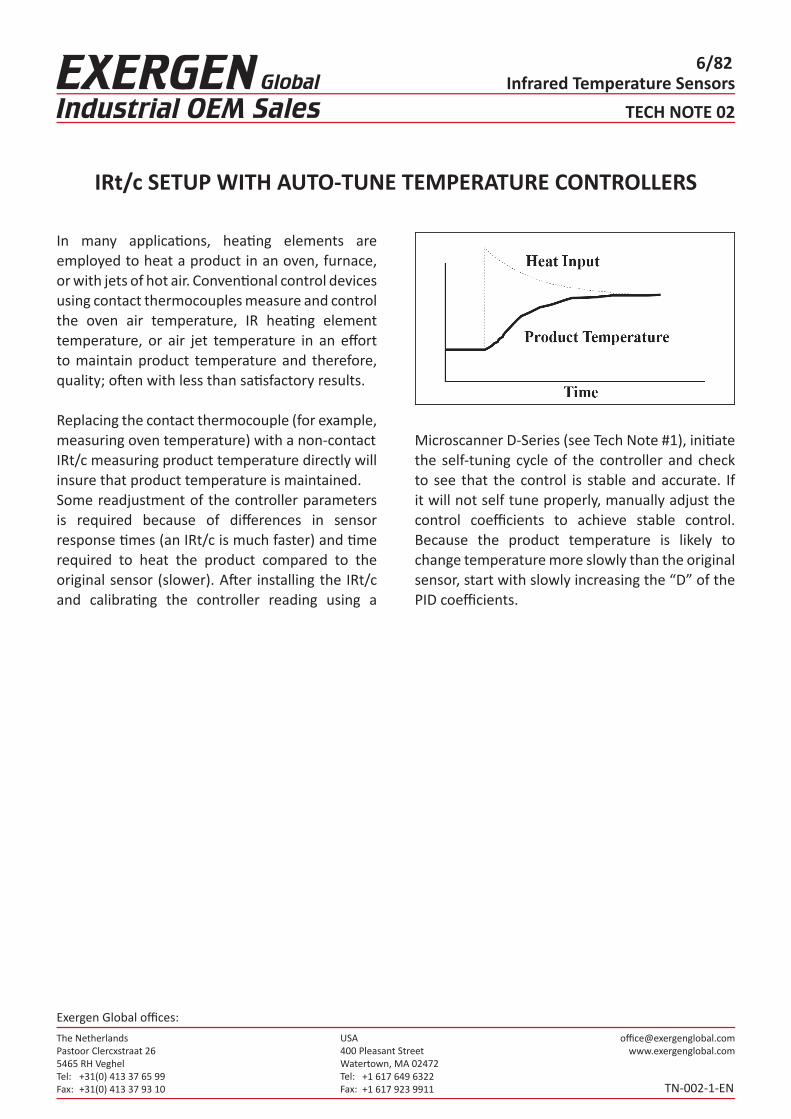
In many applications, heating elements are employed to heat a product in an oven, furnace, or with jets of hot air. Conventional control devices using contact thermocouples measure and control the oven air temperature, IR heating element temperature, or air jet temperature in an effort to maintain product temperature and therefore, quality; often with less than satisfactory results.
Replacing the contact thermocouple (for example,measuring oven temperature) with a non-contactIRt/c measuring product temperature directly willinsure that product temperature is maintained.Some readjustment of the controller parameters is required because of differences in sensor response times (an IRt/c is much faster) and time required to heat the product compared to the original sensor (slower). After installing the IRt/c and calibrating the controller reading using a
IRt/c SETUP WITH AUTO-TUNE TEMPERATURE CONTROLLERS
TECH NOTE 02
Microscanner D-Series (see Tech Note #1), initiate the self-tuning cycle of the controller and check to see that the control is stable and accurate. If it will not self tune properly, manually adjust the control coefficients to achieve stable control. Because the product temperature is likely to change temperature more slowly than the original sensor, start with slowly increasing the “D” of the PID coefficients.
TN-002-1-EN

The NetherlandsPastoor Clercxstraat 265465 RH Veghel Tel: Fax:
+31(0) 413 37 65 99+31(0) 413 37 93 10
USA400 Pleasant StreetWatertown, MA 02472Tel: Fax:
+1 617 649 6322+1 617 923 9911
Exergen Global offices:
Infrared Temperature Sensors7/82
With twisted shielded pair thermocouple extension wire, an IRt/c can be mounted as far as 1,000 ft (300 meters) from the readout device, even in a very fierce electrical noise environment. The extraordinary noise suppression characteristics designed into the IRt/c make this possible, without using a transmitter. The IRt/c housing is electrically isolated from the signal leads and is connected to the shielded ground of the extension cable. For long distances, the twisted shielded extension cable should be used, and the shield connected to a good electrical ground.
A demonstration test was performed with a 1000 ft (300 m) coil of twisted shielded pair of extensionwire, with 100 ft (30 m) unwound, connecting an IRt/c to a fast (100 msec response) A/D conversion
IRt/c CAN BE USED WITH UP TO 1,000 FEET (300 M)OF THERMOCOUPLE EXTENSION WIRE
TECH NOTE 03
module to a computer. As a noise generator, a 60 Hz 10,000 volt transformer and spark generator was set up to spark within 6 inches (15 cm) of the wire. The test results showed less than 0.1°C of noise at any relative position of the wire, spark, and transformer.
TN-003-1-EN

The NetherlandsPastoor Clercxstraat 265465 RH Veghel Tel: Fax:
+31(0) 413 37 65 99+31(0) 413 37 93 10
USA400 Pleasant StreetWatertown, MA 02472Tel: Fax:
+1 617 649 6322+1 617 923 9911
Exergen Global offices:
Infrared Temperature Sensors8/82
A rather logical combination of heating method and control is radiant heat with an IRt/c for control. They work extraordinarily well together, since both theheating and measuring occur right at the surface, where the paint is located. The IRt/c reading is unaffected by reflections from the heater, since the spectral response of the 6-14 micron IRt/c lens filters out the shorter wavelengths of the radiant heater energy.
The IRt/c may be mounted in the shroud or reflector of the radiant heater, such that it can see through the elements. Select any of the IRt/c models, depending on the field-of-view required to see past the elements to the painted surface. Test the location by turning on the heater with no target present. The change in reading should be small. Care should be taken in mounting the IRt/c in such a way as to keep its temperature below 200°F (93°C) and to keep the lens clean. The IRt/c.3x, .5, and .10 are the preferred models
IRt/c CONTROLS PAINT CURING WITH RADIANT HEATERS
TECH NOTE 04
for this application because of their built-in air purge. They can be used in environments with temperatures up to 250°F (121°C) or higher when the air purge system is used. The narrow fields-of-view allow more leeway in positioning, and thus more flexibility in installation.
TN-004-1-EN

The NetherlandsPastoor Clercxstraat 265465 RH Veghel Tel: Fax:
+31(0) 413 37 65 99+31(0) 413 37 93 10
USA400 Pleasant StreetWatertown, MA 02472Tel: Fax:
+1 617 649 6322+1 617 923 9911
Exergen Global offices:
Infrared Temperature Sensors9/82
A common problem in processing of paper and other material is measuring temperature in an area in which steam (water) is used to heat and cool the material. The resulting steam vapor makes it very difficult to use non-contact infrared devices because steam vapor is opaque to infrared wavelengths commonly used, i.e. the sensor cannot see through the vapor fog very well, and thus would report temperatures that were too low. In addition, condensing steam vapor on the sensor lens would render the IRt/c completely blind to infrared wavelengths.
The IRt/c air purge models solve the problems in asimple and inexpensive fashion. The air jet from the built-in air purge clears a path to the target material by “blowing away” the steam vapor in
TEMPERATURE MEASUREMENTS IN STEAMING ENVIRONMENTS
TECH NOTE 07
the optical path, replacing it with dry air. Care is required in the set-up of distance to the target and air pressureemployed, to prevent cooling of the target area bythe air jet.
TN-007-1-EN

The NetherlandsPastoor Clercxstraat 265465 RH Veghel Tel: Fax:
+31(0) 413 37 65 99+31(0) 413 37 93 10
USA400 Pleasant StreetWatertown, MA 02472Tel: Fax:
+1 617 649 6322+1 617 923 9911
Exergen Global offices:
Infrared Temperature Sensors10/82
“Field Apparatus having energy storing or generating characteristics of <1.2V, 0.1A, 25 mW or 25 microJ shall be considered Simple Apparatus (nonenergy storing). These general purpose devices may be used in a hazardous (classified) location without further approval when connected to a certified intrinsically safe circuit.” -Quote from R. Stahl, Inc. Comprehensive Product Manual OnIntrinsic Safety Barrier and Repeater Relays.Examples of non-energy storing Intrinsically SafeApparatus are:
• Thermocouples, RTD’s, LED’s• Dry Switch Contacts• NAMUR Inductive Proximity Switches• Non-inductive Strain Gauge Devices and
Resistors
IRt/c’S ARE INTRINSICALLY SAFE WHEN USED WITH BARRIERS
TECH NOTE 10
The IRt/c falls into the category of thermocouples,since it generates its signal by converting the radiated heat energy to an electrical signal via Seebeck effects, the basic driving force of thermocouples. Like all thermocouples, it requires no power source and generates signals measured in millivolts of voltage, microamps of current and nanowatts of power. IRt/c’s have a small capacitance, but at one microFarad, the energy storage is measured in nanojoules and is a thousand times lower than the 25 microjoule criterion.
Accordingly, the IRt/c qualifies as a Simple Apparatus for use in hazardous locations, and with the appropriate barrier, qualifies as Intrinsically Safe.
TN-010-1-EN

The NetherlandsPastoor Clercxstraat 265465 RH Veghel Tel: Fax:
+31(0) 413 37 65 99+31(0) 413 37 93 10
USA400 Pleasant StreetWatertown, MA 02472Tel: Fax:
+1 617 649 6322+1 617 923 9911
Exergen Global offices:
Infrared Temperature Sensors11/82
An occasional problem introduced by switching-type thermocouple dataloggers is signal offset caused by the switching transient. The IRt/c is a completely passive device and produces an electrical signal entirely via thermoelectric effects, but does contain both resistance and capacitance above the levels found with conventional thermocouples. Many interface devices generate a small leakage current, which induces no shift in signal with conventional low impedance (<100 ohm) thermocouples, but may induce an offset with the higher IRt/c impedance (~3K ohm). This type of offset is normally stable and is simply calibrated out by adjusting the device’s OFFSET or ZERO adjustment.
However, switching the thermocouple input can also cause offsets in IRt/c readout due to the presence of capacitance, if the signal leads are connected
MULTIPLEXED DATALOGGING APPLICATIONS
TECH NOTE 14
in a differential fashion to the amplifier input. A switching transient voltage stores a charge in the capacitance, which can cause the equivalent of leakage current offset. This offset could also be calibrated out, but may not be stable. A preferred method is simply to ground the negative side of the t/c input as shown.
The ground provides a path for the charge causedby the switching transient to dissipate, thus eliminating the offset. The twisted shielded pair wire with shield connected to ground will compensate for any loss of noise rejection, and thus provide a clean signal.
TN-014-1-EN

The NetherlandsPastoor Clercxstraat 265465 RH Veghel Tel: Fax:
+31(0) 413 37 65 99+31(0) 413 37 93 10
USA400 Pleasant StreetWatertown, MA 02472Tel: Fax:
+1 617 649 6322+1 617 923 9911
Exergen Global offices:
Infrared Temperature Sensors12/82
Very often the environment inside an oven contains vapors from the process which may condense on cooler surfaces inside the oven. When an IRt/c is used inside the oven to monitor the temperature of the process, the IRt/c must be cooled if the environment is above 212°F (100°C). Using the convenient IRt/c Cooling Jacket Kit available, either air or water may be used. For temperatures above 700°F (370°C) water is required, along with a small amount of purge air.
The purge air has two important functions:1. It keeps the IRt/c lens clear of vapors that
would condense on its window, since the window temperature might be below the condensing temperature of some of the vapors of the process.
2. The internal convective heat transfer characteristics are optimal for cooling at very high environmental temperatures.
AIR PURGING IS RECOMMENDED WHEN USING WATER COOLING
TECH NOTE 15
The IRt/c.3x is particularly suited for this service since the air consumption required to keep its lens clean is as little as .01 CFM (300 cc/min). A small convenient self-contained air pump is available.
TN-015-1-EN
The NetherlandsPastoor Clercxstraat 265465 RH Veghel Tel: Fax:
+31(0) 413 37 65 99+31(0) 413 37 93 10
USA400 Pleasant StreetWatertown, MA 02472Tel: Fax:
+1 617 649 6322+1 617 923 9911
Exergen Global offices:
Infrared Temperature Sensors13/82
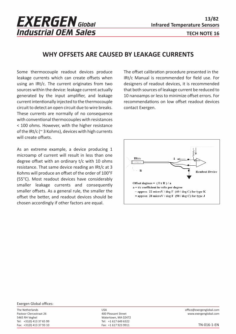
Some thermocouple readout devices produce leakage currents which can create offsets when using an IRt/c. The current originates from two sources within the device: leakage current actuallygenerated by the input amplifier, and leakage current intentionally injected to the thermocouplecircuit to detect an open circuit due to wire breaks.These currents are normally of no consequence with conventional thermocouples with resistances < 100 ohms. However, with the higher resistance of the IRt/c (~ 3 Kohms), devices with high currents will create offsets.
As an extreme example, a device producing 1 microamp of current will result in less than one degree offset with an ordinary t/c with 10 ohms resistance. That same device reading an IRt/c at 3 Kohms will produce an offset of the order of 100°F (55°C). Most readout devices have considerably smaller leakage currents and consequently smaller offsets. As a general rule, the smaller the offset the better, and readout devices should be chosen accordingly if other factors are equal.
WHY OFFSETS ARE CAUSED BY LEAKAGE CURRENTS
TECH NOTE 16
The offset calibration procedure presented in theIRt/c Manual is recommended for field use. For designers of readout devices, it is recommended that both sources of leakage current be reduced to 10 nanoamps or less to minimize offset errors. For recommendations on low offset readout devices contact Exergen.
TN-016-1-EN

The NetherlandsPastoor Clercxstraat 265465 RH Veghel Tel: Fax:
+31(0) 413 37 65 99+31(0) 413 37 93 10
USA400 Pleasant StreetWatertown, MA 02472Tel: Fax:
+1 617 649 6322+1 617 923 9911
Exergen Global offices:
Infrared Temperature Sensors14/82
Much of the production of modern society is heldtogether by means of adhesives, and without on-line inspection equipment, modern high volume production machinery can quickly fill a warehouse with improperly bonded scrap. Hot melt adhesive is probably the most widely used because of its solvent-free operation, high setting speed, and economy of use. With upwards of 100,000 hot melt “guns” in operation, there are many thousands of installations that can benefit from on-line inspection.
Hot melt bonding power is a function primarily of hot melt quantity and temperature. The more adhesive applied, the greater the area bonded. The hotter the adhesive, the less viscous it is - it becomes better able to “grip” the substrate material. However, if the hot melt is too hot, it chars, forming a residue which plugs the injection nozzles of the guns. Nonmeltable contaminants also enter the melting system at times. These contaminants also eventually clog the nozzle or filters. Either way, the adhesive flow is blocked and poor product is produced.
A pair of IRt/c’s, wired differentially (connect the minus leads together and measure across the plusleads) reliably detects the infrared energy radiatedby the adhesive. This heat energy is proportional to the amount and temperature of the adhesive it sees, which in turn is an excellent indication of the hot melt bonding power. Wired differentially, one IRt/c will give a (+) response to heat, while the other will give a (-) response to heat. Fixture the (+) IRt/c to view the adhesive shortly after it is applied by the gun.
DETECTING HOT MELT ADHESIVE IN PRODUCT ASSEMBLY, PACKAGING
TECH NOTE 18
Fixture the (-) IRt/c to view an area of the substrate in which there is no adhesive. The (-) IRt/c is called the Reference, since it automatically compensates the (+) unit for any changes in substrate temperature, such that the net signal provided by the IRt/c pair is created only by the net heat of the adhesive being added to the substrate (the hot melt being applied properly to the carton, etc.).
The Reference IRt/c is a very powerful tool. It can be located next to the (+) IRt/c for corrugated carton, on the under side of a plastic base cup while hot melt is applied to the top, or upstream of a coating head with the (+) downstream. The differential pair of IRt/c’s will reliably report the presence or absence of hot melt compared to a reference area by the presence or absence of the characteristic heat signature. With set-up calibration, the pair of IRt/c’s will also indicate quantitatively how much hot melt is being applied.
The IRt/c.3x is usually the model of choice due to its smaller tip, narrower field-of-view, and built-in air purge for dirty environments, but any of the IRt/c models may be used. The output signal from the differential pair is in the range of 1 millivolt for a typical set-up. Any suitable amplifier can be used.
TN-018-1-EN

The NetherlandsPastoor Clercxstraat 265465 RH Veghel Tel: Fax:
+31(0) 413 37 65 99+31(0) 413 37 93 10
USA400 Pleasant StreetWatertown, MA 02472Tel: Fax:
+1 617 649 6322+1 617 923 9911
Exergen Global offices:
Infrared Temperature Sensors15/82
Since the IRt/c’s are measuring differentially, no cold junction compensation is required, and might cause errors if present. The amplified signal can be interfaced by computer, PLC, or other control device. Be sure to “design in” adequate sensitivity adjustment. For best performance, it is recommended that both IRt/c’s are mounted in a single aluminum fixture in order to minimize any thermal differences between them.
DETECTING HOT MELT ADHESIVE IN PRODUCT ASSEMBLY, PACKAGING
TECH NOTE 18
TN-018-1-EN
Set up and operation involve fixturing the IRt/c’s at the desired inspection points, operating the adhesive applications at the minimum acceptable adhesive level, then adjusting the alarm limits to that level.

The NetherlandsPastoor Clercxstraat 265465 RH Veghel Tel: Fax:
+31(0) 413 37 65 99+31(0) 413 37 93 10
USA400 Pleasant StreetWatertown, MA 02472Tel: Fax:
+1 617 649 6322+1 617 923 9911
Exergen Global offices:
Infrared Temperature Sensors16/82
Like the IRt/c, the pit viper has the ability to “see”infrared radiation.
Pit vipers comprise a family of snakes that share asophisticated thermal adaptation that stems fromthe evolution of specialized pit organs located near their eyes. These organs sense the infrared radiation of an approaching warm-blooded animal and send signals to the snake’s brain. These signals are used with the visual picture provided by the snake’s eyes, giving the snake more complete information about its environment.
Pit organs are small facial cavities covered by a thin membrane of sensory cells that respond to temperature differences between the target and the snake’s body temperature. These sense organs are so sensitive they can resolve differences of just .003°C. Pit vipers can detect the presence of a warmblooded animal at distances of up to 50 centimeters in total darkness simply from the animal’s infrared radiation. The pit viper quickly and accurately scans the target with its infrared-sensing pit organs before deciding to strike to defend its nest or attack its prey.
HOW THE PIT VIPER MEASURES INFRARED RADIATION
TECH NOTE 19
TN-019-1-EN
The NetherlandsPastoor Clercxstraat 265465 RH Veghel Tel: Fax:
+31(0) 413 37 65 99+31(0) 413 37 93 10
USA400 Pleasant StreetWatertown, MA 02472Tel: Fax:
+1 617 649 6322+1 617 923 9911
Exergen Global offices:
Infrared Temperature Sensors17/82
TECH NOTE 21
TN-021-1-EN
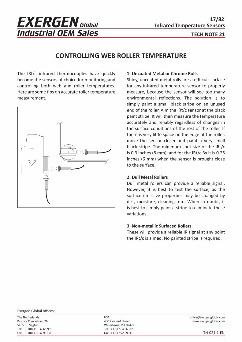
The IRt/c infrared thermocouples have quickly become the sensors of choice for monitoring and controlling both web and roller temperatures. Here are some tips on accurate roller temperature measurement.
1. Uncoated Metal or Chrome RollsShiny, uncoated metal rolls are a difficult surface for any infrared temperature sensor to properly measure, because the sensor will see too many environmental reflections. The solution is to simply paint a small black stripe on an unused end of the roller. Aim the IRt/c sensor at the black paint stripe. It will then measure the temperature accurately and reliably regardless of changes in the surface conditions of the rest of the roller. If there is very little space on the edge of the roller, move the sensor closer and paint a very small black stripe. The minimum spot size of the IRt/c is 0.3 inches (8 mm), and for the IRt/c.3x it is 0.25 inches (6 mm) when the sensor is brought close to the surface.
2. Dull Metal RollersDull metal rollers can provide a reliable signal. However, it is best to test the surface, as the surface emissive properties may be changed by dirt, moisture, cleaning, etc. When in doubt, it is best to simply paint a stripe to eliminate these variations.
3. Non-metallic Surfaced RollersThese will provide a reliable IR signal at any point the IRt/c is aimed. No painted stripe is required.
CONTROLLING WEB ROLLER TEMPERATURE

The NetherlandsPastoor Clercxstraat 265465 RH Veghel Tel: Fax:
+31(0) 413 37 65 99+31(0) 413 37 93 10
USA400 Pleasant StreetWatertown, MA 02472Tel: Fax:
+1 617 649 6322+1 617 923 9911
Exergen Global offices:
Infrared Temperature Sensors18/82
TECH NOTE 22
TN-022-1-EN
For forming plastics, radiant heat with an IRt/c is an excellent combination of heating method and control. They work extraordinarily well together, since both the heating and measuring occur right at the surface, where the plastic is located. The IRt/c reading is unaffected by reflections from the heater, since the spectral response of the 6 to 14 micron IRt/c lens filters out the shorter wavelengths of the radiant heater energy.
The IRt/c may be mounted in between ceramic heaters, or in the shroud or reflector of the radiantheater, such that it can see in between the elements. Select any of the IRt/c models, depending on the field-of-view required to see past the elements to the painted surface. Care should be taken in mounting the IRt/c in such a way as to keep its temperature below 200°F (93°C) and to keep the lens clean. The IRt/c.3x is the
preferred model for this application because of its small physical size and builtin air purge. It can be used in temperatures up to 250°F (121°C) when the air purge system is used. For still narrower fields of view, the IRt/c.5 and IRt/c.10 with 5:1 and 10:1 FOV respectively are very popular.
CONTROLLING VACUUM FORMING AND THERMOFORMING PROCESSES

The NetherlandsPastoor Clercxstraat 265465 RH Veghel Tel: Fax:
+31(0) 413 37 65 99+31(0) 413 37 93 10
USA400 Pleasant StreetWatertown, MA 02472Tel: Fax:
+1 617 649 6322+1 617 923 9911
Exergen Global offices:
Infrared Temperature Sensors19/82
TECH NOTE 24
TN-024-1-EN
IRt/c CONTROLS PRODUCT DRYING (PAPER, WOOD, TEXTILES, FILM)
In processing of products such as paper, wood and textiles, it is important to be able to determine quickly when the products are sufficiently dry.
The surface temperature of a “wet” product will change (rise) very slowly as constant heat is applied to the product. This occurs because the moisture in the product absorbs much of the heat energy as it evaporates. At the point that the product becomes “dry”, however, the same constant heat supply will quickly raise the temperature until it reaches the same as the surrounding air, or higher if the heat source is radiation. If temperature vs. time is plotted for a heated drying process, the target “dry” temperature point can clearly be seen as the beginning of a rapid rise in surface temperature.
IRt/c’s can be used to monitor these changes in surface temperature. With their fast 0.1 second response time, IRt/c’s can quickly detect when the surface temperature begins to rise rapidly, an indication that the products have reached a low moisture content. (See also Tech Note No. 67)
T
time( or position)
A simple implementation method is to measure the difference in temperature between the product and the ambient air. Determine the delta T that results in the correct dryness, and set the control system to maintain that delta T.
The IRt/c is particularly convenient because it can be wired differentially with an ordinary thermocouple. The combined signal can be fed to a single control channel. Alternatively, if absolute temperature is preferred, the IRt/c and thermocouple can be read and controlled independently.
For hot, humid, dusty environments, the IRt/c.3x is recommended because of its small size and super-efficient purge air system. Fully developed, patented IRt/c-based drying systems are available. Contact Exergen for referrals.
+
+
+
- TemperatureDifferential
Dry Air
+ +
-
DryA ir +
-
Temperature
DryA ir
Product

The NetherlandsPastoor Clercxstraat 265465 RH Veghel Tel: Fax:
+31(0) 413 37 65 99+31(0) 413 37 93 10
USA400 Pleasant StreetWatertown, MA 02472Tel: Fax:
+1 617 649 6322+1 617 923 9911
Exergen Global offices:
Infrared Temperature Sensors20/82
TECH NOTE 26
TN-026-1-EN
IRt/c REPEATABILITY AND LONG-TERM ACCURACY
The ability of the measuring device to maintain itscalibration under service conditions and over a long period of time is of fundamental interest in temperature control. The IRt/c is rated at less than 0.1°C repeatability and has no measurable long term calibration change, which makes it well suited for reliable temperature control. These attributes are inherent in the basic design and construction of each IRt/c.
Repeatability is defined as the ability of a measuring device to reproduce its calibration under identical conditions. The IRt/c is a solid, hermetically sealed, fully potted system that does not change mechanically or metallurgically during service. There are no active electronic components and no power source to produce the signal – only the thermoelectric effects that produce a thermocouple signal. Long term accuracy is influenced by the same things that influence repeatability: mechanical changes and metallurgical changes. It is well known that thermocouples can change calibration over time due to these effects.
Mechanical changes occur because conventional thermocouples are generally constructed as smalland light as possible to enhance response time, making them vulnerable to deformations that canchange the thermoelectric properties. More importantly the conventional thermocouple must operate at elevated temperature since it merely measures its own temperature.
The metallurgical changes which affect thermoelectric properties are a strong function of temperature; they are negligible at room temperature, but are of serious concern at high temperature.
The IRt/c solves both problems by its design and basic operation. Its solid fully potted construction in a mechanically rigid stainless steel housing, andoperation at near room temperature conditions, essentially eliminate the classical drift problems of conventional thermocouples. Every IRt/c is double annealed at temperatures above 212°F (100°C) to ensure long term stability, and tested five times prior to packaging. Barring a small percentage of failure, the IRt/c has essentially unlimited long term calibration accuracy.

The NetherlandsPastoor Clercxstraat 265465 RH Veghel Tel: Fax:
+31(0) 413 37 65 99+31(0) 413 37 93 10
USA400 Pleasant StreetWatertown, MA 02472Tel: Fax:
+1 617 649 6322+1 617 923 9911
Exergen Global offices:
Infrared Temperature Sensors21/82
TECH NOTE 28
TN-028-1-EN
IRt/c TROUBLE SHOOTING GUIDE
There are only three possible failure modes for an IRt/c sensor. If an IRt/c sensor is installed and does not function as expected the failure may be due to something other than the sensor. It is recommended that the sensor is checked out for response after installation to ensure that it is connected to the readout instrument properly. This can be done simply by placing a hand or a heat source in front of the sensor after it is installed and making sure the reading changes (this is still valid even if the temperature is well below the calibration point). If the sensor gives a reading very different from the expected reading:
1. Check initial calibration. If the controller has been changed, or the offset adjusted after the sensor has been installed, the temperature reading may be very different from the actual temperature.
2. Check the sensor lens. If dirt has accumulated on the lens over time, then the reading may be lower than expected. Clean the lens using a Q-tip and alcohol. The lens needs to be treated gently, it can be easily scratched.
3. If the sensor reading does not change even thought the target temperature is changing, the sensor may be burnt out. Check the impedance of the sensor, if the impedance is >15kohm, then the sensor is probably burnt out. If the impedance is <100ohm, then there is a short in the thermocouple wire and the temperature being measured is at the short.
4. If the temperature suddenly reads about half of what it should, then the hermetic seal may be compromised and the Xenon gas may have escaped.
For more information regarding the calibration testing of IRt/c sensors, see Tech Note #74. For process control applications, the system can be programmed to check the sensor circuit every time it is powered up, see Tech Note #39. If a PLC is used for process control, a sensor short will have the same effect as a “Heater Burn Out Protection” feature.

The NetherlandsPastoor Clercxstraat 265465 RH Veghel Tel: Fax:
+31(0) 413 37 65 99+31(0) 413 37 93 10
USA400 Pleasant StreetWatertown, MA 02472Tel: Fax:
+1 617 649 6322+1 617 923 9911
Exergen Global offices:
Infrared Temperature Sensors22/82
TECH NOTE 29
TN-029-1-EN
IRt/c CAN MEASURE OBLIQUELY
Often, an area needs to be temperature monitored,but because of space limitations, the IRt/c cannot be placed to view the target area squarely. In suchsituations the IRt/c can be angled obliquely to view the target area. The field-of-view then becomeselliptical instead of circular, and the IRt/c averagesthe temperature it sees.
To apply this method, be sure to estimate the size of the field-of-view footprint, and confirm that the IRt/c is measuring the area you wish to measure.

The NetherlandsPastoor Clercxstraat 265465 RH Veghel Tel: Fax:
+31(0) 413 37 65 99+31(0) 413 37 93 10
USA400 Pleasant StreetWatertown, MA 02472Tel: Fax:
+1 617 649 6322+1 617 923 9911
Exergen Global offices:
Infrared Temperature Sensors23/82
TECH NOTE 30
TN-030-1-EN
IRt/c MEASURES VIBRATING OBJECTS
Measuring the temperature of objects that are nominally stationary, but vibrate, can be a difficult problem because of mechanical fatigue of any contact device. An example is continuous monitoring of the casing temperature of both the turbine and compressor side of a turbocharger. Thermocouples or other contact devices fail after only a few hours due to the high frequency vibration present during turbocharger operation.
The IRt/c provides a simple and inexpensive solution. Mounting the IRt/c’s to a non-vibrating surface, they can monitor the turbocharger temperature without being subject to the destructive vibration.
Wherever there is a requirement for machinery monitoring, temperature should be included; and for machines that vibrate, the best solution is the IRt/c.

The NetherlandsPastoor Clercxstraat 265465 RH Veghel Tel: Fax:
+31(0) 413 37 65 99+31(0) 413 37 93 10
USA400 Pleasant StreetWatertown, MA 02472Tel: Fax:
+1 617 649 6322+1 617 923 9911
Exergen Global offices:
Infrared Temperature Sensors24/82
TECH NOTE 31
TN-031-1-EN
WHAT IS EMISSIVITY?
Emissivity is a surface property which determines how much radiation an object emits at a given temperature compared to a blackbody at the same temperature. Emissivity (along with background thermal radiation) is a primary source of errors ininfrared temperature measurement. Emissivity can be more easily understood if it is realized that infrared has similar properties to visible light.
Mirrors figure prominently in the discussion of heat radiation and emissivity*. Since heat and light radiation behave similarly, what we see with our eyes is similar to what the IRt/c sees. When you look in a mirror with your eyes, you see only reflections, nothing of the mirror itself. If themirror is perfect, it has 100% reflectivity. Therefore,it emits nothing because it reflects everything. Forthis condition, the emissivity is zero.
If we consider an imperfect mirror, the eye then sees mostly reflection, but also some of the imperfections on the mirror surface. If, for example, we saw 90% of the mirror as a perfect reflector and 10% as imperfections, 90% of the mirror would reflect; the remaining 10% would emit. Therefore, the emissivity equals 0.1.
Consider for a moment the exact opposite of a perfect mirror, which is a perfect emitter. The eye looks at a perfect emitter and sees no reflection at all, only the emitting surface. Since 100% of the surface emits, and 0% reflects, the emissivity equals 1.0. This type of object is called a blackbody.
Finally, consider a good emitter. The eye sees asmall amount of reflection interspersed with thelarge amount emitting. If 10% of the surface did notemit, and instead reflected, we would have 10% reflecting and the remaining 90% emitting. Therefore, the emissivity equals 0.9.
Accordingly, we can state the following rule of emissivity:
The emissivity of a surface is simply thepercentage of the surface that emits. Theremaining percentage of the surface reflects.
Shiny metal surfaces act like mirrors, with emissivities in the range 0.05 to 0.2. Accordingly, they have only 4% to 25% emitting area compared to reflecting area, and for that reason
are difficult to measure with infrared methods. Non-metals, organic materials, and coated metals have emissivities in the range of 0.8 to 0.95 and thus have 400% to 1900% emitting area compared to reflecting area, and thus are much more easily measured successfully.
*See “Through the LookingGlass-The Story of Alice’s Quest for Emissivity” available from Exergen.
The NetherlandsPastoor Clercxstraat 265465 RH Veghel Tel: Fax:
+31(0) 413 37 65 99+31(0) 413 37 93 10
USA400 Pleasant StreetWatertown, MA 02472Tel: Fax:
+1 617 649 6322+1 617 923 9911
Exergen Global offices:
Infrared Temperature Sensors25/82
TECH NOTE 32
TN-032-1-EN
WHERE IS THE EMISSIVITY ADJUSTMENT?
In the readout device.
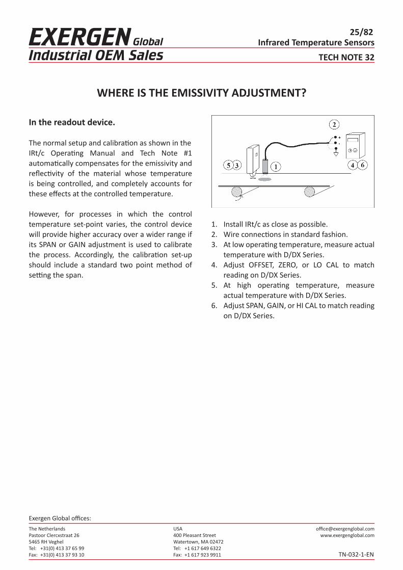
The normal setup and calibration as shown in theIRt/c Operating Manual and Tech Note #1 automatically compensates for the emissivity and reflectivity of the material whose temperature is being controlled, and completely accounts for these effects at the controlled temperature.
However, for processes in which the control temperature set-point varies, the control device will provide higher accuracy over a wider range if its SPAN or GAIN adjustment is used to calibrate the process. Accordingly, the calibration set-up should include a standard two point method of setting the span.
1. Install IRt/c as close as possible.2. Wire connections in standard fashion.3. At low operating temperature, measure actual
temperature with D/DX Series.4. Adjust OFFSET, ZERO, or LO CAL to match
reading on D/DX Series.5. At high operating temperature, measure
actual temperature with D/DX Series.6. Adjust SPAN, GAIN, or HI CAL to match reading
on D/DX Series.
The NetherlandsPastoor Clercxstraat 265465 RH Veghel Tel: Fax:
+31(0) 413 37 65 99+31(0) 413 37 93 10
USA400 Pleasant StreetWatertown, MA 02472Tel: Fax:
+1 617 649 6322+1 617 923 9911
Exergen Global offices:
Infrared Temperature Sensors26/82
TECH NOTE 33
TN-033-1-EN
WHY THE D/DX SERIES IS RECOMMENDED FOR IRt/c TEMPERATURE CONTROL CALIBRATION
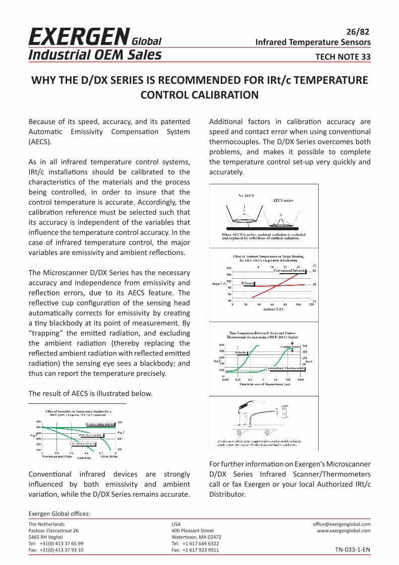
Because of its speed, accuracy, and its patented Automatic Emissivity Compensation System (AECS).
As in all infrared temperature control systems, IRt/c installations should be calibrated to the characteristics of the materials and the process being controlled, in order to insure that the control temperature is accurate. Accordingly, the calibration reference must be selected such that its accuracy is independent of the variables that influence the temperature control accuracy. In the case of infrared temperature control, the major variables are emissivity and ambient reflections.
The Microscanner D/DX Series has the necessary accuracy and independence from emissivity and reflection errors, due to its AECS feature. The reflective cup configuration of the sensing head automatically corrects for emissivity by creating a tiny blackbody at its point of measurement. By “trapping” the emitted radiation, and excluding the ambient radiation (thereby replacing the reflected ambient radiation with reflected emitted radiation) the sensing eye sees a blackbody; and thus can report the temperature precisely.
The result of AECS is illustrated below.
Conventional infrared devices are strongly influenced by both emissivity and ambient variation, while the D/DX Series remains accurate.
Additional factors in calibration accuracy are speed and contact error when using conventional thermocouples. The D/DX Series overcomes both problems, and makes it possible to complete the temperature control set-up very quickly and accurately.
For further information on Exergen’s Microscanner D/DX Series Infrared Scanner/Thermometers call or fax Exergen or your local Authorized IRt/c Distributor.

The NetherlandsPastoor Clercxstraat 265465 RH Veghel Tel: Fax:
+31(0) 413 37 65 99+31(0) 413 37 93 10
USA400 Pleasant StreetWatertown, MA 02472Tel: Fax:
+1 617 649 6322+1 617 923 9911
Exergen Global offices:
Infrared Temperature Sensors27/82
TECH NOTE 34
TN-034-1-EN
CHECKING IRt/c AMBIENT TEMPERATURE
In many installations, it may not be clear whether cooling is required, and it may not be easy to obtain the temperature of the environment experienced by the IRt/c. The IRt/c itself will tell you what its own temperature is, by using the procedure illustrated below.
The basic method is to temporarily “blind” the IRt/c using aluminum foil, so that it can only see itself. The temperature that it produces is then its own temperature only.
Before running this test, be sure to check for leakage current offsets as described in the manual.

The NetherlandsPastoor Clercxstraat 265465 RH Veghel Tel: Fax:
+31(0) 413 37 65 99+31(0) 413 37 93 10
USA400 Pleasant StreetWatertown, MA 02472Tel: Fax:
+1 617 649 6322+1 617 923 9911
Exergen Global offices:
Infrared Temperature Sensors28/82
TECH NOTE 35
TN-035-1-EN
AIR PURGE AND AIR COOLING REQUIREMENTS
The limiting air flow restriction for all of the IRt/cmodels and Cooling Jacket Kit is the air fitting supplied with the unit. Accordingly, all IRt/c’s withbuilt-in air purge, and the Cooling Jacket Kit (CJK-1) all have essentially the same pressure vs. air flow characteristics, and the air flow chart applies to all. However, the air consumption requirements for purging or cooling for each are somewhat different due to size and operation variables. Refer to the table or chart for specific model requirements for minimum pressure for purging, or for cooling in elevated ambient conditions. IRt/c.xxx refers to allmodels with the 1.375” (34,9 mm) housing
diameter. If water cooling is used with the Cooling Jacket Kit, air purge pressure only is required.

The NetherlandsPastoor Clercxstraat 265465 RH Veghel Tel: Fax:
+31(0) 413 37 65 99+31(0) 413 37 93 10
USA400 Pleasant StreetWatertown, MA 02472Tel: Fax:
+1 617 649 6322+1 617 923 9911
Exergen Global offices:
Infrared Temperature Sensors29/82
TECH NOTE 37
TN-037-1-EN
SELECTING TEMPERATURE CONTROLLERS
IRt/c infrared thermocouples are designed to be used with all thermocouple readout devices and controllers, but due to the higher impedance levels of the IRt/c compared to standard t/c’s, some controllers are better suited than others. Leakage current generated by the controller (see Tech Note #16) creates an offset in reading which should be adjusted out for accurate temperatures. If the offset produced by the leakage current is larger than the available offset adjustment of the controller, the IRt/c will still produce repeatable readings and control
accurately, but the temperature indication will be incorrect. Accordingly, recommended controllers are those which have low leakage currents and/or sufficient offset adjustment to produce an accurate IRt/c reading (see chart for relationship between leakage current and offset).
Following is a list of controller manufacturers with models known to have low leakage currents and are recommended for use with the IRt/c:
Athena, Cal Controls, Eurotherm, Fenwal, Fuji, Honeywell, Love, Newport, Omega, Omron, Partlow, Red Lion, Syscon, Watlow, Yamatake- Honeywell, Shinko Technos
This list is not a comprehensive one - manufacturers are constantly improving their models. Contact your local Authorized IRt/c Distributor for specific models, or the controller manufacturer to inquire as to suitability of specific models for service with an IRt/c (sensor impedance of ~5 Kohms).

The NetherlandsPastoor Clercxstraat 265465 RH Veghel Tel: Fax:
+31(0) 413 37 65 99+31(0) 413 37 93 10
USA400 Pleasant StreetWatertown, MA 02472Tel: Fax:
+1 617 649 6322+1 617 923 9911
Exergen Global offices:
Infrared Temperature Sensors30/82
TECH NOTE 38
TN-038-1-EN
HOW THE IRt/c IS MANUFACTURED FOR RELIABILITY
The IRt/c is designed and manufactured to provide a lifetime of reliable operation in the most demanding service conditions. To assure this performance, every IRt/c is put through a rigorous process of manufacture, including seven separate test stages. At the end of this process, the IRt/c is ready to be installed, and is ready to provide you with reliable infrared temperature data for many years.
As an additional reliability feature, all IRt/c’s are manufactured with a Xenon gas fill hermetically sealed into the sensing system. If the hermetic seal is broken by mechanical or thermal damage to the sensor, the Xenon immediately escapes, and the IRt/c radiation sensitivity (difference
between target and sensor temperature) immediately drops by more than a factor of two, thus providing an obvious indication of failure, rather than a gradual change which can cause poor quality service for a long period of time before a failure is detected.

The NetherlandsPastoor Clercxstraat 265465 RH Veghel Tel: Fax:
+31(0) 413 37 65 99+31(0) 413 37 93 10
USA400 Pleasant StreetWatertown, MA 02472Tel: Fax:
+1 617 649 6322+1 617 923 9911
Exergen Global offices:
Infrared Temperature Sensors31/82
TECH NOTE 39
TN-039-1-EN
A SOFTWARE METHOD OF SELF-TESTING IRt/c’S
For many OEM applications, it is important to be able to test the IRt/c for proper operation each time the system is started, assuring the user that all systems are functioning, much the same way that a microprocessor can be programmed to check itself when powered up. This feature is especially useful to check for cleanliness of the lens in applications where a user might inadvertently spill something on its surface.
The test is performed by applying a known powerinput to the target to be heated, and monitoring the initial rate of change of temperature of the target as seen by the IRt/c. This rate of change is dependent only on the power level and independent of the initial temperature of the target, as long as the target began at a uniform temperature. Sufficient time must be allowed after the previous powerdown.
If the IRt/c is clean and functioning normally, it willreport the correct rate of change, and the machinebecomes operational. If the rate of change is lowerthan normal, the user is alerted to clean the lens. If this still does not produce the desired response,service is required on the IRt/c or heater, target, control, etc.

The NetherlandsPastoor Clercxstraat 265465 RH Veghel Tel: Fax:
+31(0) 413 37 65 99+31(0) 413 37 93 10
USA400 Pleasant StreetWatertown, MA 02472Tel: Fax:
+1 617 649 6322+1 617 923 9911
Exergen Global offices:
Infrared Temperature Sensors32/82
TECH NOTE 45
TN-045-1-EN
PRINTING/INK DRYING
For high speed printing processes, the limiting factor on productivity of the equipment is usually ink drying time. With non-contact monitoring of the inked surface temperature, press production can be maximized while assuring top quality.
The surface temperature of freshly inked paper will be considerably cooler than ambient air temperature, and will rise very slowly as the paper absorbs heat. This occurs because the ink solvent absorbs much of the heat energy as it evaporates.
At the point that the product becomes “dry,” however, the same constant heat supply will quickly raise the temperature until it reaches the same as the surrounding air, or higher if the heat source is radiation. If temperature vs. time is plotted for a heated drying process, the target “dry” temperature point can clearly be seen as the beginning of a rapid rise in surface temperature.The IRt/c’s can be used to monitor these changes in surface temperature. With their fast response time, the IRt/c’s can quickly detect when the surface temperature begins to rise rapidly, an indication that the ink has dried, thus allowing press speeds to be maximized. Since all IRt/c’s are rated intrinsically safe (see Tech Note # 10), and are hermetically sealed to meet or exceed all applicable NEMA ratings, they can be used in hazardous environments with alcohol-based and other volatile inks. For tight areas, the IRt/c.SV or IRt/c.3SV is recommended.
The NetherlandsPastoor Clercxstraat 265465 RH Veghel Tel: Fax:
+31(0) 413 37 65 99+31(0) 413 37 93 10
USA400 Pleasant StreetWatertown, MA 02472Tel: Fax:
+1 617 649 6322+1 617 923 9911
Exergen Global offices:
Infrared Temperature Sensors33/82
TECH NOTE 49
TN-049-1-EN
HOW THE IRt/c TEMPERATURE SELECTION GUIDE WORKS
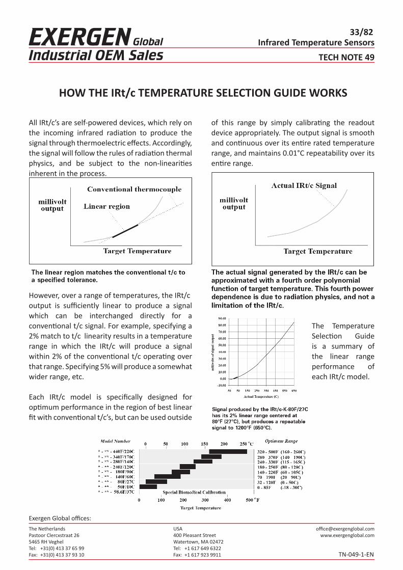
All IRt/c’s are self-powered devices, which rely on the incoming infrared radiation to produce the signal through thermoelectric effects. Accordingly, the signal will follow the rules of radiation thermal physics, and be subject to the non-linearities inherent in the process.
However, over a range of temperatures, the IRt/coutput is sufficiently linear to produce a signal which can be interchanged directly for a conventional t/c signal. For example, specifying a 2% match to t/c linearity results in a temperature range in which the IRt/c will produce a signal within 2% of the conventional t/c operating over that range. Specifying 5% will produce a somewhat wider range, etc.
Each IRt/c model is specifically designed for optimum performance in the region of best linear fit with conventional t/c’s, but can be used outside
of this range by simply calibrating the readout device appropriately. The output signal is smooth and continuous over its entire rated temperature range, and maintains 0.01°C repeatability over its entire range.
The Temperature Selection Guide is a summary of the linear range performance of each IRt/c model.

The NetherlandsPastoor Clercxstraat 265465 RH Veghel Tel: Fax:
+31(0) 413 37 65 99+31(0) 413 37 93 10
USA400 Pleasant StreetWatertown, MA 02472Tel: Fax:
+1 617 649 6322+1 617 923 9911
Exergen Global offices:
Infrared Temperature Sensors34/82
TECH NOTE 52
TN-052-1-EN
SPEED OF RESPONSE
One of the outstanding features of the IRt/c is itsspeed of response – 0.05 to 0.2 seconds. This attribute makes it possible to monitor the temperature of fast moving materials in production lines, and rapid heating and cooling. For applications in which high speed is required, care should be taken in selection of the readout device, since most thermocouple readouts are much slower than the IRt/c.
In applying the IRt/c, the dynamic characteristicscan be described mathematically as a pure exponential response, following the equation:
Accordingly, the IRt/c signal can be modeled analytically for applications in which faster speedsare required. For any given IRt/c, the time constantwill be repeatable to within a few percent, and thus can be successfully modelled.
A common limitation in applying the IRt/c to high speed applications is the transit time of the targetacross the field of view. The characteristic time constant equation of response applies to the IRt/cresponse only. If the target requires time to completely fill the field of view, the transit time
must be added to the IRt/c time constant. For best results, place the IRt/c as close as possible to the target to minimize the spot size, and therefore the transit time effect.

The NetherlandsPastoor Clercxstraat 265465 RH Veghel Tel: Fax:
+31(0) 413 37 65 99+31(0) 413 37 93 10
USA400 Pleasant StreetWatertown, MA 02472Tel: Fax:
+1 617 649 6322+1 617 923 9911
Exergen Global offices:
Infrared Temperature Sensors35/82
TECH NOTE 53
TN-053-1-EN
IRt/c QUICK SELECTION GUIDE
1. How Large Is Your Target?• If it is smaller than 0.8 inches (2 cm), you
must select either the micro IRt/c, micro IRt/c.4, IRt/c.2G, IRt/c.01, IRt/c.03, IRt/c.1x, IRt/c.3x, or focused model.
• If it is smaller than 0.3 inches (8 mm) you must select the IRt/c.3x or focused model.
• If it is larger than 0.8 inches (2 cm), select any of the sensors.
2. How Close Can The Sensor Be Mounted?• See Tech Note #36, Tech Note #41, and Tech
Note #55 and use the field-of-view drawings showing the distance from the sensor versus the approximate diameters of the spot size.
• For example, the IRt/c.3x, at a distance of 3X has a spot size of 1X (at a distance of 1 foot, the spot size is 4 inches, at a distance of 1.5 meter, the spot size is 0.5 meter).
• See Tech Note #29 if you wish to position an IRt/c at an angle other than 90° from your target surface.
• If using a focused model, refer to individual model specifications for optimum distance.
3. What Is The Ambient Temperature Where The Sensor Is To Be Placed?• If ambient is less than 160°F (70° C) choose
any sensor.• If ambient is less than 185°F (85°C) choose
any sensor except micro IRt/c, IRt/c.01 and IRt/c.03.
• micro IRt/c, IRt/c.01 and IRt/c.03If ambient is less than 212°F (100° C) choose any sensor except IRt/c.01 and IRt/c.03.
• If ambient is greater than 212°F (100° C), see Tech Note #35 for air cooling flow requirements for the IRt/c Cooling Jacket Kit and IRt/c.XXX built-in air purge/cool system.
• If ambient is greater than 500°F (260°C), it is usually best to specify an IRt/c or IRt/c.2 sensor along with the Cooling Jacket Kit and utilize the water cooling feature. (Cooling the smaller sensors with water is less expensive over time, compared to cooling the IRt/c.5 with air.)
4. What Is Your Target Temperature?• Use Temperature Selection Guide. See Tech
Note #49.
5. Choosing A Temperature Controller/InputDevice?• See Tech Note #37 and Tech Note #14
for help in selecting or using available thermocouple input devices.

The NetherlandsPastoor Clercxstraat 265465 RH Veghel Tel: Fax:
+31(0) 413 37 65 99+31(0) 413 37 93 10
USA400 Pleasant StreetWatertown, MA 02472Tel: Fax:
+1 617 649 6322+1 617 923 9911
Exergen Global offices:
Infrared Temperature Sensors36/82
TECH NOTE 55
TN-055-1-EN
UNDERSTANDING FIELD-OF-VIEW
IRt/c’s are rated optically for their field-of-view by the actual dimensional equations describing their construction. However there are, in practice, some secondary effects which can influence performance, including optical scatter, unwanted reflections, atmospheric scatter, and others.
The graph illustrates the relative contribution to the signal produced by the target and by the area surrounding the target due to these effects. Notethat the sum of radiation from the target and radiation from the surroundings is always one, and as the sensor is placed further away than its rated field-of-view, there is less target signal and more surroundings signal. Mathematically this effect is identical to a reduction in emissivity, and can be calibrated out the same way, as long as the temperature of the surroundings is repeatable.
Under typical conditions, placing the IRt/c such that the target exactly fills the field of view results in approximately 80 to 90% target signal, and 10 to 20% surroundings signal.
A common convention in infrared thermometry, and the one used to verify the optical performance of IRt/c’s, is to define the field-of-view by the “1/2energy points” in an optical traverse experiment.The resultant data looks like a “Bell Curve” as indicated in the illustration. The field-of-view is simply the angle between the 50% energy points.
As always, closer is best; use the closest possible position for the IRt/c.
The NetherlandsPastoor Clercxstraat 265465 RH Veghel Tel: Fax:
+31(0) 413 37 65 99+31(0) 413 37 93 10
USA400 Pleasant StreetWatertown, MA 02472Tel: Fax:
+1 617 649 6322+1 617 923 9911
Exergen Global offices:
Infrared Temperature Sensors37/82
TECH NOTE 56
TN-056-1-EN
CALIBRATING WITH THERMOCOUPLE SIMULATORS
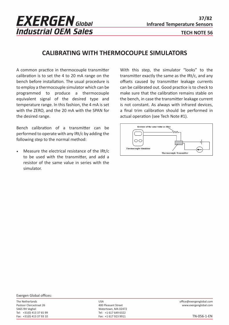
A common practice in thermocouple transmitter calibration is to set the 4 to 20 mA range on the bench before installation. The usual procedure is to employ a thermocouple simulator which can beprogrammed to produce a thermocouple equivalent signal of the desired type and temperature range. In this fashion, the 4 mA is set with the ZERO, and the 20 mA with the SPAN for the desired range.
Bench calibration of a transmitter can be performed to operate with any IRt/c by adding the following step to the normal method:
• Measure the electrical resistance of the IRt/c to be used with the transmitter, and add a resistor of the same value in series with the simulator.
With this step, the simulator “looks” to the transmitter exactly the same as the IRt/c, and any offsets caused by transmitter leakage currents can be calibrated out. Good practice is to check to make sure that the calibration remains stable on the bench, in case the transmitter leakage current is not constant. As always with infrared devices, a final trim calibration should be performed in actual operation (see Tech Note #1).

The NetherlandsPastoor Clercxstraat 265465 RH Veghel Tel: Fax:
+31(0) 413 37 65 99+31(0) 413 37 93 10
USA400 Pleasant StreetWatertown, MA 02472Tel: Fax:
+1 617 649 6322+1 617 923 9911
Exergen Global offices:
Infrared Temperature Sensors38/82
TECH NOTE 57
TN-057-1-EN
MEASURING OBJECTS SMALLER THAN THE FIELD-OF-VIEW
For some non-contact temperature monitoring tasks, the object to be measured is too small to adequately fill the field-of-view of one of the IRt/c models. The monitoring can still be successfully performed if two conditions are met:• The object size and distance from the IRt/c are constant.• The area surrounding the object within the field-of-view of the IRt/c has a repeatable
temperature.The signal produced by the IRt/c represents the average temperature within its view. Accordingly, the signal can be represented by the equation:
where T is the output signal, Tt the target object temperature, At the target object area, Ts the surroundings temperature, As the surroundings area as seen by the IRt/c, and A the total area seen by the IRt/c.
For example, to measure the temperature of a thin rubber strip 0.1” (2.5 mm) wide moving continuously 1” (25 mm) away from an IRt/c.2, at a temperature expected to be about 200°F (93°C), and a surrounding temperature at 80°F (27°C). At 1” (25 mm) distance, the IRt/c.2 spot size will be approximately 0.5” (13 mm).
Computing the results for the equation gives:
This result shows that the average signal will be 31°F (17°C) above the surroundings temperature, compared to an actual object temperature of 120°F (67°C) above surroundings, or approximately one-fourth, which is the ratio of object area to surroundings area measured. Therefore, if the surroundings are expected to be repeatable to 1°F (.6°C), the IRt/c signal will be repeatable to 4°F (2°C). For the final display on a controller, or other read-out device, calibrate in standard fashion by using the available offset adjustment. If the object is to be controlled over a wide range of temperatures, calibrating with a span adjustment will yield greater accuracy.
If the target temperature falls within the range of one of the LoE models, the LoE model should be used, even if the target is not metallic. Since a small target results in the same radiation mathematics as low emissivity, a LoE model will reduce errors due to size change and positioning by a factor of approximately 4. See Tech Note 59.

The NetherlandsPastoor Clercxstraat 265465 RH Veghel Tel: Fax:
+31(0) 413 37 65 99+31(0) 413 37 93 10
USA400 Pleasant StreetWatertown, MA 02472Tel: Fax:
+1 617 649 6322+1 617 923 9911
Exergen Global offices:
Infrared Temperature Sensors39/82
TECH NOTE 59
TN-059-1-EN
HOW THE LO E FILTER REDUCES ERRORS DUE TO EMISSIVITY VARIATIONS
Emissivity is the property of a material’s surface that describes its “efficiency” at emitting thermal radiation. An emissivity value of 1.0 represents emission at 100%, and 0 describes emission at 0% (or perfect reflection - see Tech Note #31).
For non-metals and coated metals this efficiency of emission, called emissivity, is very high (0.8 or greater), and variations are usually not a problem. For example, for a production process in which a non-metallic material is to be controlled, and normal material variations cause emissivity variations of ±.01, the associated temperature error will be of the order of .01 divided by .9, or ~1% of reading, an acceptable variation. In contrast, if we are to control the temperature of a metal with emissivity 0.2, then variations of ±.01 will produce an error of the order of (.01/.2), or ~ 5% of reading. Additionally, metal finishes, which play a significant role in emissivity, tend to cause more variations than changes in finish in non-metals.
The IRt/c Lo E Filter design filters out the effects ofthese emissivity variations on measured temperature by approximately a factor of four, and thus reduces the errors by a factor of four. Thus, with the Lo E Filter, the errors are of the same order as those commonly experienced for high emissivity targets.
The method takes advantage of the basic physics of thermal radiation, in which the mathematical description of the energy distribution is by a formula called the Planck function:
where is radiated energy at a given wavelength, is the emissivity, T the absolute target temperature, the wavelength, and the other symbols are for various physical constants. The Planck function integrates to the more familiar Stefan-Boltzman equation:
when all wavelengths are measured. The Lo E Filter works by measuring the energy content of the radiation, as described by the Planck function, over wavelengths that are more selectively sensitive for temperature variations, and thereforeproportionately less sensitive to emissivity variations, as follows:
The NetherlandsPastoor Clercxstraat 265465 RH Veghel Tel: Fax:
+31(0) 413 37 65 99+31(0) 413 37 93 10
USA400 Pleasant StreetWatertown, MA 02472Tel: Fax:
+1 617 649 6322+1 617 923 9911
Exergen Global offices:
Infrared Temperature Sensors40/82
TECH NOTE 59
TN-059-1-EN
HOW THE LO E FILTER REDUCES ERRORS DUE TO EMISSIVITY VARIATIONS
If we compute the partial derivative of each expression with respect to emissivity and temperature, we obtain the following relations for the slope of the signal with respect to temperature divided by the slope of the signal with respect to emissivity:
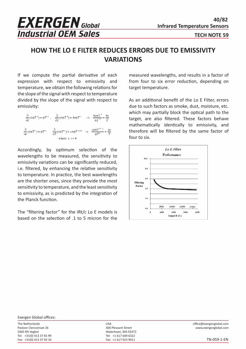
Accordingly, by optimum selection of the wavelengths to be measured, the sensitivity to emissivity variations can be significantly reduced, i.e. filtered, by enhancing the relative sensitivity to temperature. In practice, the best wavelengths are the shorter ones, since they provide the most sensitivity to temperature, and the least sensitivity to emissivity, as is predicted by the integration of the Planck function.
The “filtering factor” for the IRt/c Lo E models is based on the selection of .1 to 5 micron for the
measured wavelengths, and results in a factor of from four to six error reduction, depending on target temperature.
As an additional benefit of the Lo E Filter, errors due to such factors as smoke, dust, moisture, etc. which may partially block the optical path to the target, are also filtered. These factors behave mathematically identically to emissivity, and therefore will be filtered by the same factor of four to six.
The NetherlandsPastoor Clercxstraat 265465 RH Veghel Tel: Fax:
+31(0) 413 37 65 99+31(0) 413 37 93 10
USA400 Pleasant StreetWatertown, MA 02472Tel: Fax:
+1 617 649 6322+1 617 923 9911
Exergen Global offices:
Infrared Temperature Sensors41/82
TECH NOTE 62
TN-062-1-EN
WHY COLOR DOES NOT AFFECT READINGS
In many IRt/c installations, such as paint curing, web drying, printing, etc., the temperature control system must be able to accurately measure materials with a variety of colors. Ideally the same calibration set-up would be used for all colors, rather than having to recalibrate each time a new color is run.
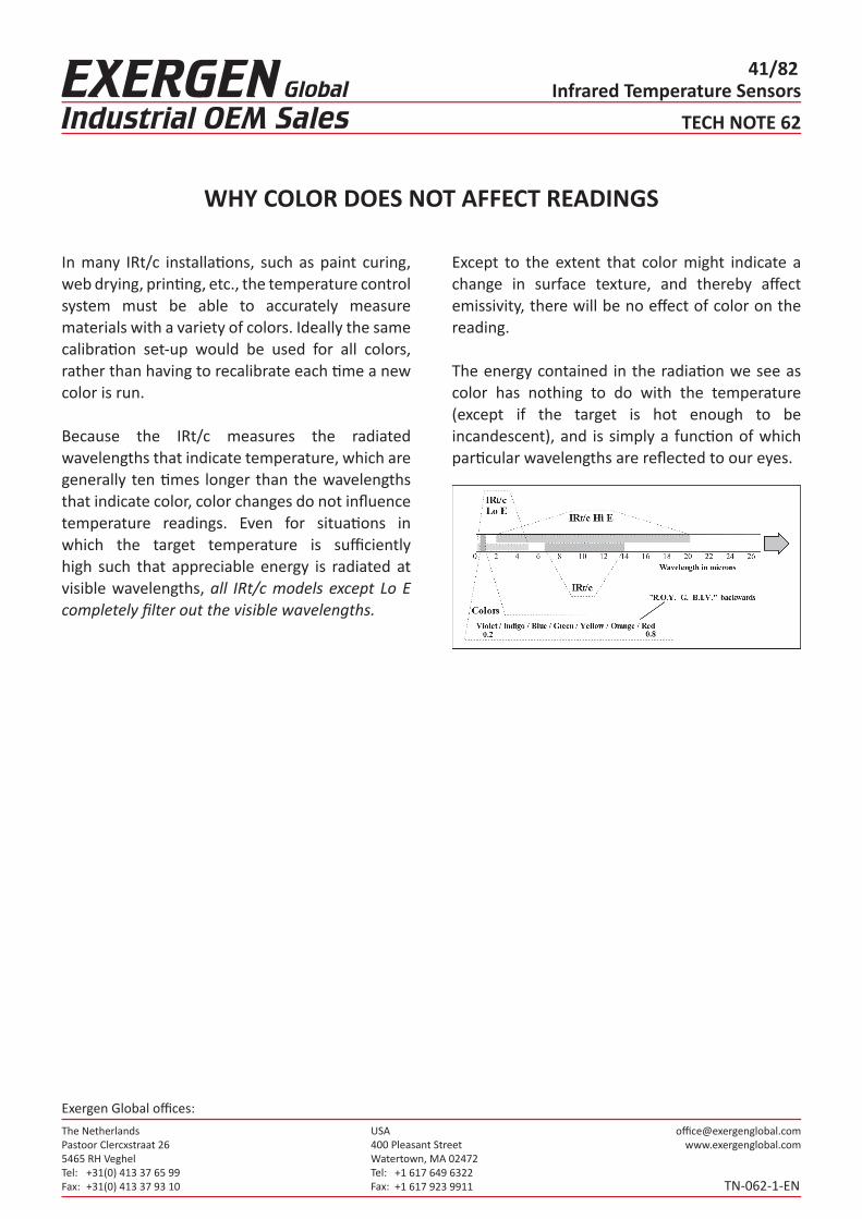
Because the IRt/c measures the radiated wavelengths that indicate temperature, which are generally ten times longer than the wavelengths that indicate color, color changes do not influence temperature readings. Even for situations in which the target temperature is sufficiently high such that appreciable energy is radiated at visible wavelengths, all IRt/c models except Lo E completely filter out the visible wavelengths.
Except to the extent that color might indicate a change in surface texture, and thereby affect emissivity, there will be no effect of color on the reading.
The energy contained in the radiation we see as color has nothing to do with the temperature (except if the target is hot enough to be incandescent), and is simply a function of which particular wavelengths are reflected to our eyes.

The NetherlandsPastoor Clercxstraat 265465 RH Veghel Tel: Fax:
+31(0) 413 37 65 99+31(0) 413 37 93 10
USA400 Pleasant StreetWatertown, MA 02472Tel: Fax:
+1 617 649 6322+1 617 923 9911
Exergen Global offices:
Infrared Temperature Sensors42/82
TECH NOTE 67
TN-067-1-EN
MEASURING LOCATION OF DRY-OUT POINT IN WEB PRODUCTION
For many types of continuous web production processing, such as paper, printing, photographicfilm, textiles, etc., an important parameter for quality and throughput rate is knowledge of the point at which “dry-out” occurs. More important even than the absolute temperature, the location of this point provides a highly precise indication of the rate of heat input into the product, and allows direct control of the energy input to force the dry-out point to a specific spot in the drying process.
The IRt/c is particularly well suited to this application due to its small size, low cost, outstanding speed, hermetically sealed construction, and its intrinsically safe character.
Connected to inexpensive multi-channel thermocouple input cards for PLC’s or computers, the dryout point is easily calculated by the intersection of the slopes of the temperature vs. position data provided by the IRt/c’s.

The NetherlandsPastoor Clercxstraat 265465 RH Veghel Tel: Fax:
+31(0) 413 37 65 99+31(0) 413 37 93 10
USA400 Pleasant StreetWatertown, MA 02472Tel: Fax:
+1 617 649 6322+1 617 923 9911
Exergen Global offices:
Infrared Temperature Sensors43/82
TECH NOTE 68
TN-068-1-EN
FAIL-SAFE CONTROL INSTALLATION METHODS
Although extraordinarily reliable, like any other measuring device, an IRt/c installation should be designed to “fail-safe” under all foreseeable situations. Accordingly, the possible failure modesshould be considered as part of the installation design, as recommended in the Operating Principles Manual supplied with every IRt/c.
Open Circuit Detection As in all thermocouple installations, a primary protection recommended is open circuit detection, which will alert if wires are
broken, or if the IRt/c is physically damaged to the point of opening the electrical circuit. Standard circuit techniques involve using a small leakage current that generates negligible voltage when the circuit is closed, but drives the input amplifier into saturation if the circuit opens. Only a very small amount of current is required, ~ 1 nanoamp, which produces a negligible signal offset with the higher impedance of the IRt/c, although some devices produce far more current than required, and thus produce more offset (seeTech Notes #16, 37).
Short Circuit DetectionAlso a commonly available feature of thermocouple control devices, this safety feature detects if the load is on solidly for a time that is too long for the normalprocess requirements. This would be the case if a thermocouple were shorted somewhere between the measuring junction and the controller, and thus not reporting the temperature of the process, but the temperature at the short. This safety feature in a controller is
highly recommended, since it not only will protect against short circuits, but also against any other possible failure in the IRt/c which might maintain electrical continuity, but renders it blind to the process.
Calibration DriftThere are no known processes that can cause a significant calibration drift in the IRt/c. Since thereare no active electrical components, the signal is generated entirely by thermoelectric effects, and the materials are kept at comfortably low temperatures. A significant feature of the IRt/c design and construction is the presence of a Xenon gas fill in the detection system, which provides an immediate and dramatic change in sensitivity (factor of ~ 3) if mechanical damage occurs sufficient to cause a leak (see Tech Note #38). A common apparent source of drift can be a dirty lens, since the optical signal will degrade in direct proportion to the lens area blocked. Employing the built-in air purge feature of most IRt/c’s prevents this problem.
IRt/c Self-TestA powerful method of checking an IRt/c installation is to test the response against an expected range on every measurement cycle. This option is highly recommended if there is computing power available, since it takes full advantage of the fact that any failure of the IRt/c will result in a dramatic change in sensitivity; and thus failure to respond to normal thermal processes will be easy to detect. Refer to Tech Note #39 for further details.

The NetherlandsPastoor Clercxstraat 265465 RH Veghel Tel: Fax:
+31(0) 413 37 65 99+31(0) 413 37 93 10
USA400 Pleasant StreetWatertown, MA 02472Tel: Fax:
+1 617 649 6322+1 617 923 9911
Exergen Global offices:
Infrared Temperature Sensors44/82
TECH NOTE 71
TN-071-1-EN
PRINTING PRESS APPLICATIONS
IRt/c infrared thermocouples are revolutionizing the printing industry because their small size allows them to be mounted in the tight spaces typical of both web and sheet fed presses, and their low cost allows economical installation and control on even the smallest of presses. Additionally, since many presses are already equipped with thermocouple controllers and PLC thermocouple inputs, the IRt/c is a simple installation.
Applications include not only printing onto paper, but also cloth, plastic, and any other printing webapplication.
Location 1: INK ROLLERS, PLATENSCONVENTIONAL PRESSES (water/ink)
On conventional presses (water/ink processes), the quality of the process is very dependent on the difference in surface tension between water and ink, and this surface tension is highly temperaturesensitive. When presses operate, heat is generateddue to friction in the pressing area. Heat build-upcan significantly alter the surface tension of thewater/ink resulting in a deterioration in print quality.
IRt/c sensors easily monitor any roll surface temperatures within presses. Connected to a display with alarm signal, they can alert the operator of deteriorating temperature conditions before poor quality impressions are made. Connected to a temperature controller, PLC or computer, the IRt/c quickly signals an installed press temperature control system to provide cooling to the press area, or signal cooling systems to provide cooling to the ink and/or water supplies to maintain proper surface tension.
Temperature is also important when there is risk of thin wall cylindrical platen(s) becoming loose orsloppy due to thermal expansion (or contraction). On large diameter metal cylinders, a small temperature change can result in a significant change in the circumference of the roll, and thus affect the proper “fit.” By measuring the surface temperature of the roll, the proper fit of the plate can be maintained by either (1) cooling the area or (2) slowing down the press so friction heat decreases to a low enough level to maintain printquality.
WATERLESS INK PRESSES and CONVERSIONS
“Waterless” ink technology involves the use of special inks to eliminate the need for the water/ink combination. This technology has significant cost and performance advantages for the printer in elimination of waste treatment, and higher quality product. The waterless ink technology can be applied to virtually all types (web and sheet fed) and sizes of presses from large multi-color presses down to the small presses.
Conventional presses can be converted to use these inks by providing a method to control the surface temperature of the rolls where the ink is applied to the platens. This is typically done by using hollow rolls and supplying chilled water

The NetherlandsPastoor Clercxstraat 265465 RH Veghel Tel: Fax:
+31(0) 413 37 65 99+31(0) 413 37 93 10
USA400 Pleasant StreetWatertown, MA 02472Tel: Fax:
+1 617 649 6322+1 617 923 9911
Exergen Global offices:
Infrared Temperature Sensors45/82
dryer, it runs through a chill roller(s) to cool the web so that the paper (cloth, plastic, etc.) can be cut and stacked, or rolled, without the material sticking together.
By using IRt/c sensors to measure the surface temperature of the web at the point where it is being chilled, the IRt/c signal can control the amount of chilling. This control will eliminate “over chilling” (condensation problems due to high ambient humidity common in press rooms) and “underchilling” problems, automatically.
Location 4: BINDERYHot melt glue guns and applicators periodically “plug up” or run out of glue. Properly used IRt/c sensors or an Exergen AAM system can instantly alert machine operators prior to products being glued improperly. See Tech Note #18 and/or the section on the Exergen AAM Series (Applied Adhesive Monitors) in The IRt/c Book.
TECH NOTE 71
TN-071-1-EN
PRINTING PRESS APPLICATIONS
through the rolls to keep the surface at a desired temperature. The IRt/c is a key component of the package required to convert a press, since waterless inks are very temperature sensitive and must be applied with strict ink and surface temperature control.
The surface temperatures are easily monitored byan IRt/c. The output signal is sent to a discrete temperature controller, PLC, or custom computer control system to regulate the refrigerated circulators providing cooling water.
The IRt/c sensing system is precise enough to alsoallow manipulation of color characteristics for waterless printing. For example, running a particular waterless ink at different temperature extremes allows for choosing between brilliant or softer colors.
Location 2: DRYING/CURINGAfter ink is applied to the paper (or cloth, plastic, etc.) in the printing area, the web (or sheet) typically travels through a drying/curing process. IRt/c sensors are used where they (1) “look” directly at the web or sheet while it is inside the dryer or (2) at the web just as it exits the dryer. Either method can be used to control drying temperature or UV curing.
For web presses, a much more accurate way is also possible. By using multiple IRt/c sensors along theweb while in the dryer, the actual “Dry-Out” point can be located and controlled within the dryer. See Tech Note #67.
Location 3: CHILL ROLLERSFor web offset printing, as the web leaves the

The NetherlandsPastoor Clercxstraat 265465 RH Veghel Tel: Fax:
+31(0) 413 37 65 99+31(0) 413 37 93 10
USA400 Pleasant StreetWatertown, MA 02472Tel: Fax:
+1 617 649 6322+1 617 923 9911
Exergen Global offices:
Infrared Temperature Sensors46/82
TECH NOTE 72
TN-072-1-EN
OEM LOW COST INTERFACE
Designing the advantages of infrared temperaturesensing into your OEM equipment is now easier and much, much lower cost than it has ever been. The IRt/c product line can be conveniently interfaced with many standard thermocouple devices at the component level for custom board design. For example, Analog Devices, Inc. manufactures numerous lowcost thermocouple input components that work well with the IRt/c, such as the following two models.
Model AD1B60 Intelligent Digitizing Signal Conditioner for the IRt/c
• Complete IRt/c sensor-to-digital signal conditioning and data conversion
• Directly connect up to 4 IRt/c’s per chip• Cold junction compensation built in• Software switchable open thermocouple
detection• Allows IRt/c linearization over complete
temperature sensing range• Digital output• Under $50 in 100 piece quantities
Model AD594 (type J), AD595 (type K) IRt/c Amplifier with CJC• Direct connection with IRt/c sensors• Built-in cold junction compensation• 10 mV/deg C output (0 to 10 V output)• Under $7 per unit in 100 piece quantities
(AD594AQ)For more information about component level IRt/c design, or assistance in board level design forinterface with the IRt/c product line, please contact Exergen directly. Contact Analog Devices directly for information on these and other models: Analog Devices, Inc., One Technology Way, PO Box 9106, Norwood, MA 02062 (Phone: 800-262-5643, 617-329-4700)

The NetherlandsPastoor Clercxstraat 265465 RH Veghel Tel: Fax:
+31(0) 413 37 65 99+31(0) 413 37 93 10
USA400 Pleasant StreetWatertown, MA 02472Tel: Fax:
+1 617 649 6322+1 617 923 9911
Exergen Global offices:
Infrared Temperature Sensors47/82
TECH NOTE 74
TN-074-1-EN
CALIBRATION TESTING PROCEDURES
For many OEM and general temperature control applications it is sometimes desirable to test sensors before being placed into service, or to conduct routine checking while they are in service.Accordingly, recommended procedures are presented to allow easy checking with commonly available equipment. However, prior to testing, it is important to understand what indications an actual IRt/c failure might cause.
Factory CalibrationThe pre-calibrated IRt/c sensors (models without the “A” suffix that indicates user adjustability) arecalibrated under conditions that optimize performance in actual use: target emissivity = 0.9 (a good general value for non-metals), and ambient temperature elevated to approximately 1/4 of the elevation of target temperature above room temperature (accurately simulates the effect of reflected energy). Since this type of test would require specialized devices, the procedures outlined have test standards that are slightly different, since they use blackbodies, or test surfaces/ambients whose properties vary to some extent.
What to Look For When TestingOpen Circuit: An open circuit (resistance > 15 KW)indicates a broken wire, and open circuit detectionsystems will perform normally to detect it.
No Response to Thermal Radiation: Sensor reads ambient temperature accurately, but does not respond when pointed at a hot target. This fault issimilar to a short circuit with an ordinary thermocouple, in that the circuit is complete, but is measuring the ambient temperature at the short, and not at the measuring junction. For the
IRt/c, this fault is the same as if the sensor were covered with foil, thus blinding it.
Sensor Reads Low: There are only two ways an IRt/c can shift after factory calibration: the lens becomes dirty; or the sensor loses its hermeticallysealed Xenon gas.
• If the lens becomes dirty, the signal loss is directly proportional to the amount of dirt on the lens. Infrared energy is a form of light and therefore the situation is similar to ordinary window glass becoming dirty and blocking out sunshine. If considerably dirty before cleaning, the window will let more light through after cleaning, thus increasing the signal. If it was already clean, additional cleaning doesn’t let any more light through, and the signal remains the same.
• If the durable IRt/c hermetic seal somehow fails, the Xenon gas will immediately escape. For even a small leak, the Xenon will escape quickly, within seconds. It is a “fail-safe” design. The Xenon gas will not leak gradually. If this occurs, the mV output sensitivity will immediately drop to approximately 50% or less of normal signal. For example, if a type K-180F/90C sensor looks at a high emissivity 212°F (100°C) surface and reads correctly on a thermocouple meter, or gives you 3.3 mV on a DVM, then the sensor is within specifications. If the signal is only approximately 1.7 mV, or reads in the neighborhood of 140°F (60°C) with a thermocouple meter (and the lens is clean), the fail-safe gas seal has been compromised.

The NetherlandsPastoor Clercxstraat 265465 RH Veghel Tel: Fax:
+31(0) 413 37 65 99+31(0) 413 37 93 10
USA400 Pleasant StreetWatertown, MA 02472Tel: Fax:
+1 617 649 6322+1 617 923 9911
Exergen Global offices:
Infrared Temperature Sensors48/82
TECH NOTE 74
TN-074-1-EN
CALIBRATION TESTING PROCEDURES
The fail-safe feature is quite important, since a breach of the sensor gas seal would permit contaminants to enter the sensitive detection system and cause unpredictable drift.
Conducting Pass/Fail TestingFor your convenience, 212°F (100°C) is ecommended as a test target temperature, even though it might be outside the 2% linear range of the IRt/c being tested, since the strict repeatability of the IRt/c permits it to be tested at any temperature within its specified range. A digital volt meter (DVM) with at least 0.1 mV resolution is recommended instead of a thermocouple readout, since the DVM will be faster, and will not generate a leakage current that can cause readings to vary from sensor to sensor due to resistance variations. An electronic ice point reference is desirable, but not necessary for pass/fail testing.
EquipmentBest: Accurate Blackbody at 212°F (100°C).Good Alternative: Pot of boiling water.
ProcedureMake sure the sensor window is clean. If it is not, then clean with a mild solvent such as alcohol and wipe dry. Clip the DVM test leads to the IRt/c and
point at the target, bringing the IRt/c as close as possible to be sure that the IRt/c sees only the target, taking care that the clip lead connections (the effective cold junctions) remain at room temperature. Immediately read the DVM for the correct reading. For details of test set-up for the boiling water, see Tech Note No. 75.
In-Service Inspection MethodsMeasure the surface temperature of the target (with the target at normal operating temperature) with a Microscanner D-Series infrared thermometer. Make note of the temperature. Check the IRt/c display device and make sure the reading reproduces the original value that was obtained at installation calibration. If the IRt/c reading is incorrect, clean the lens with a cotton swab and alcohol (or similar cleaner) and recheck the display. If the reading is significantly lower, the fail-safe Xenon charge has esca ped, indicating that the sensor should be replaced.
Calibration ValuesFor specifications for the mV signals that should be obtained for the test conditions obtained above, for any given model IRt/c, please fill in the data below, and mail to Exergen: [email protected]. The specifications will be return mailed to you.

The NetherlandsPastoor Clercxstraat 265465 RH Veghel Tel: Fax:
+31(0) 413 37 65 99+31(0) 413 37 93 10
USA400 Pleasant StreetWatertown, MA 02472Tel: Fax:
+1 617 649 6322+1 617 923 9911
Exergen Global offices:
Infrared Temperature Sensors49/82
TECH NOTE 75
TN-075-1-EN
CHECKING CALIBRATION OF IRt/c OR D-SERIES WITH BOILING WATER
Exergen’s Microscanner D-Series are designed as highly accurate and reliable temperature references as well as fast easy-to-use infrared scanners. Since all components making up a D-Series are drift-free there is never a requirement to calibrate the instrument once it leaves the factory, and no calibration means is provided on the instrument (except certain high temperature models). Accordingly, if the DSeries calibration has shifted from its factory setting, it requires repair since a component has failed. Similarly, non-adjustable IRt/c models are factory calibrated for life, and if they do not reproduce their calibration, they should be considered failed.
Unless you have technical experience with and have a laboratory infrared “blackbody,” this calibration checking technique is recommended by the factory. Boiling water is a physical constant, easily used, and requires no technical set-up of elaborate equipment or checking of traceable standards.
Boiling Point of Water The open boiling point of (reasonably pure) water is affected by only one factor: barometric pressure. The standard 212°F (100°C) boiling point is for a barometric pressure of 30.00 inches of Hg (mercury), or in metric terms, 1 Bar (1000 millibars). This is “normal” at sea level. Barometric pressure can be affected by elevation above sea level, and by weather conditions.
Elevation Correction: The boiling point of water islowered by approximately 2°F (1°C) for every 1000 ft (300 m) above sea level with no unusual weather conditions. If your weather is “normal” and you are not using the barometric pressure method,
you can simply use the following corrections.
Weather Conditions: If you use this method, you do not need to put in a correction for elevation above sea level. It will be automatic by using the current barometric pressure dominating your area. Barometric pressure can be much lower during especially stormy conditions (low pressure areas), and much higher during extremely cool and dry conditions (high pressure areas). Consult the weather reports on TV, in your local newspaper, or call a weather service office for current barometric conditions in your area. Barometric pressure correction factors:• 2°F / inch Hg (1°C / 30 millibars) change from
30.00 in. Hg (1 Bar)• Add to the boiling temperature for higher than
normal pressure.• Subtract for lower than normal pressures.
Checking CalibrationRequired Equipment:• Metal pot with cover, minimum 4” (10 cm) tall.• Solid paint marker or thin opaque tape.1. Use a metal pot, with cover, for boiling water.2. Fill the pot at least 1/2 fill with water.
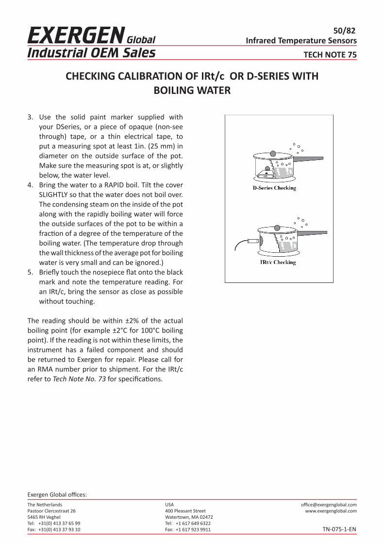
The NetherlandsPastoor Clercxstraat 265465 RH Veghel Tel: Fax:
+31(0) 413 37 65 99+31(0) 413 37 93 10
USA400 Pleasant StreetWatertown, MA 02472Tel: Fax:
+1 617 649 6322+1 617 923 9911
Exergen Global offices:
Infrared Temperature Sensors50/82
TECH NOTE 75
TN-075-1-EN
CHECKING CALIBRATION OF IRt/c OR D-SERIES WITH BOILING WATER
3. Use the solid paint marker supplied with your DSeries, or a piece of opaque (non-see through) tape, or a thin electrical tape, to put a measuring spot at least 1in. (25 mm) in diameter on the outside surface of the pot. Make sure the measuring spot is at, or slightly below, the water level.
4. Bring the water to a RAPID boil. Tilt the cover SLIGHTLY so that the water does not boil over. The condensing steam on the inside of the pot along with the rapidly boiling water will force the outside surfaces of the pot to be within a fraction of a degree of the temperature of the boiling water. (The temperature drop through the wall thickness of the average pot for boiling water is very small and can be ignored.)
5. Briefly touch the nosepiece flat onto the black mark and note the temperature reading. For an IRt/c, bring the sensor as close as possible without touching.
The reading should be within ±2% of the actual boiling point (for example ±2°C for 100°C boiling point). If the reading is not within these limits, the instrument has a failed component and should be returned to Exergen for repair. Please call for an RMA number prior to shipment. For the IRt/c refer to Tech Note No. 73 for specifications.

The NetherlandsPastoor Clercxstraat 265465 RH Veghel Tel: Fax:
+31(0) 413 37 65 99+31(0) 413 37 93 10
USA400 Pleasant StreetWatertown, MA 02472Tel: Fax:
+1 617 649 6322+1 617 923 9911
Exergen Global offices:
Infrared Temperature Sensors51/82
TECH NOTE 79
TN-079-1-EN
IRt/c’S WITHSTAND 1000G SHOCK
With simple “O-ring” mechanical supports, IRt/c’s can withstand up to 1000 g shock without damage, and without shift in calibration. Such robustness makes them well suited to heavy duty applications where high levels of shock and vibration are common.
More modest forces of 10 g can be withstood on a continuous basis, but fatigue of the cable can be a problem. Mechanical support, coiling, or other appropriate cable management is recommended.

The NetherlandsPastoor Clercxstraat 265465 RH Veghel Tel: Fax:
+31(0) 413 37 65 99+31(0) 413 37 93 10
USA400 Pleasant StreetWatertown, MA 02472Tel: Fax:
+1 617 649 6322+1 617 923 9911
Exergen Global offices:
Infrared Temperature Sensors52/82
TECH NOTE 81
TN-081-1-EN
SIDE VIEW MODEL DESIGNED FOR MONITORING WEB PROCESSES
IRt/c.SV
In heating, drying, coating, cooling, or any other thermal processing of webs of paper, plastic, metals, textiles, film, etc., often there is very littlespace available for a sensor to monitor web temperature. In a space as small as 0.56 in. (14.2 mm) the IRt/c.SV Infrared Thermocouple can be installed to monitor temperature of the moving web, and reliably control the process to maximize quality and throughput of product.
The IRt/c.SV has all of the same specifications as the standard IRt/c, including no power requirement, rugged stainless steel hermetically sealed construction, intrinsically safe, full electrical shielding, ~0.1 second response time, and ability to operate uncooled in environments up to 212°F (100°C). It is available in J,K,T,E thermocouple types, with linear range selections the same as the standard IRt/c. The solid filled 1/2 in. (12.7 mm) tubular housing can be held securely with convenient tube fittings or standard clamps to mount the sensor over the target area.

The NetherlandsPastoor Clercxstraat 265465 RH Veghel Tel: Fax:
+31(0) 413 37 65 99+31(0) 413 37 93 10
USA400 Pleasant StreetWatertown, MA 02472Tel: Fax:
+1 617 649 6322+1 617 923 9911
Exergen Global offices:
Infrared Temperature Sensors53/82
TECH NOTE 82
TN-082-1-EN
GROUNDING AND SHIELDING FOR ELECTROSTATICPROTECTION AND NOISE SUPPRESSION
Applies to All Models With Stainless Steel HousingAll IRt/c models with stainless steel housing are built with complete electrical shielding of both the housing and cable, with the measuring elements electrically isolated from the housing (as in a conventionalungrounded thermocouple). By adhering to standard good practice in grounding and shielding techniques, IRt/c’s can provide outstanding performance in the most severe electrical environments commonly found in production processes.
Q. When is attention to grounding and shieldingrequired?A. If the IRt/c must operate in extreme environments, employ long t/c cable runs, the measuring system is utilizing the high speed capability of the IRt/c,or if the process can generate high static electricity fields. For most installations, the built-in noise rejection characteristics of the IRt/c are sufficient to insure good performance, especially if the readout device is heavily filtered with a long input time constant.
Q. Can I operate ungrounded?A. Yes, but it is not recommended, especially in applications where the process can generate highstatic electricity fields. Examples are web processes of all types, including printing, laminating, film drying, etc. Without either the housing or shieldgrounded to drain away the charge, a static chargecan build in the housing, which may eventuallydischarge through the IRt/c sensing elements, andcan cause damage to the sensor.
Q. How do I use the shield correctly?A. The most important rule is to be sure the shield is grounded at only one point, preferably at the
signal input ground. Keep in mind that the housing is connected to the cable shield, and if the housing is electrically in contact with machinery at the mounting point, that point will be a ground, and the shield wire should not be connected at the instrument end. For best possible performance, electrically isolate the IRt/c at the mounting point and ground the shield at a suitable ground on the readout instrument.
Q. Can I ground the shield to the negative (red) thermocouple lead instead of to a chassis ground?A. Yes, but test both alternatives in your applicationand use the one that gives the cleanest signal. Besure that the housing is electrically isolated, otherwise ground loop currents may cause errors.
Q. Should the extension cable be shielded?A. As indicated above, if the installation requires high speed performance, twisted shielded extension cable and connectors with ground
straps should be used throughout. Aluminum foil is a suitable material to complete a shield if their are gaps in the shield coverage.

The NetherlandsPastoor Clercxstraat 265465 RH Veghel Tel: Fax:
+31(0) 413 37 65 99+31(0) 413 37 93 10
USA400 Pleasant StreetWatertown, MA 02472Tel: Fax:
+1 617 649 6322+1 617 923 9911
Exergen Global offices:
Infrared Temperature Sensors54/82
TECH NOTE 83
TN-083-1-EN
SIDE VIEW MODEL DESIGNED FOR MONITORING TEMPERATURE IN DIRTY OR VAPOR-FILLED ENVIRONMENTS
IRt/c.3SV
In heating, drying, coating, cooling, or any other thermal processing of webs of paper, plastic, metals, textiles, film, etc., often there is very littlespace available for a sensor to monitor web temperature, and the harsh environment requires a highly efficient air purge design to prevent fouling of the IR lens. In a space as small as 0.7 in. (18 mm), and in areas where ink or paint are being applied, the IRt/c.3SV Infrared Thermocouple can reliable control the process to maximize quality and throughput of product.
The IRt/c.3SV has all of the same specifications asthe standard IRt/c, including no power requirement, rugged stainless steel hermetically sealed construction, intrinsically safe, full electrical shielding, ~0.1 second response time, and ability to operate uncooled in environments up to 212°F (100°C). It is available in J, K, T, E thermocouple types, with linear range selections the same as the standard IRt/c. The solid filled 1/2 in. (12.7 mm) tubular housing can be held securely with convenient tube fittings or standard clamps to mount the sensor over the target area.
Ideal applications are offset printing, where the presence of inks and physically tight locations make the IRt/c.3SV the sensor of choice. Targets that must be monitored “upside down” are also ideal applications, since the narrow field of view and air purge will prevent debris from blocking the lens. Only 5 psig (.3 bar), which consumes less than 1 SCFM (.03 m3/min) is required for direct paint spray environments.

The NetherlandsPastoor Clercxstraat 265465 RH Veghel Tel: Fax:
+31(0) 413 37 65 99+31(0) 413 37 93 10
USA400 Pleasant StreetWatertown, MA 02472Tel: Fax:
+1 617 649 6322+1 617 923 9911
Exergen Global offices:
Infrared Temperature Sensors55/82
TECH NOTE 84
TN-084-1-EN
USING THE IRt/c.01 IN A HIGH ELECTRICAL NOISE AREA
Applies to All Models With ABS Plastic Housing
In applications where the low cost of the IRt/c.01 is important, and the other performance requirements are met by the sensor, there are occasional concerns that electrical noise in the environment can affect the readings. By employing one or more standard techniques, IRt/c.01’s can provide outstanding performance in the most severe electrical environments commonly found in machinery.
1. Employ Filtering in the Readout Device.If the readout device is heavily filtered with a long time constant, there is normally never a problem with noise. Response time constants in the range of 1 second are in common use in temperature controllers, and are usually more than enough toprevent any significant noise interference.
2. Add a Shield to either the IRt/c.01 or the EMI Source.With aluminum foil, conduit, etc. the IRt/c.01 can be shielded from the source of electromagnetic radiation directly. Be sure to properly ground the shield. Refer to Tech Note No. 82 for recommendations.
3. Consider Substituting a Fully-Shielded IRt/c Model.If none of the above options provide the necessaryperformance, especially for high speed applications, select one of the fully shielded stainless steel IRt/c models for the application.

The NetherlandsPastoor Clercxstraat 265465 RH Veghel Tel: Fax:
+31(0) 413 37 65 99+31(0) 413 37 93 10
USA400 Pleasant StreetWatertown, MA 02472Tel: Fax:
+1 617 649 6322+1 617 923 9911
Exergen Global offices:
Infrared Temperature Sensors56/82
TECH NOTE 85
TN-085-1-EN
IRt/c.01 SELECTION AND APPLICATION HINTS FOR OEMS
To assist you in specifying an IRt/c.01 model for your application, the following sequence of steps is recommended:
Locate the IRt/c.01 close enough to make the measurement accurately.Referring to the 1:1 field-of-view specification, besure that the target is large enough, or the sensorclose enough such that the target is larger than the measuring spot. The IRt/c.01 can be physicallyclose as to nearly touch the target, and is limitedonly by physical space and local temperature. Normal mounting is with the supplied locknuts (2supplied), but alternative methods may be used to hold the cylindrical section or the flats, whichever is more convenient in locating as close as practical.For hot targets in close proximity (~ 1 inch or 2,5 cm) permit adequate ventilation of the mounting to keep the IRt/c.01 below its 160°F (70°C) rating. If the sensor face is likely to become dirty, mount in such a fashion to permit occasional cleaning with a mild solvent such as alcohol.
Select the linear range required.Referring to the Temperature Selection Guide, choose the model that has the center of its linear range closest to the control point for your pplication, and select the thermocouple type you prefer. If your application includes monitoring and control over a range of more than ~ 100°F (~ 50°C),and your thermocouple interface has computational ability, request a copy of the IRt/c Signal Output Table for your model, which has the data necessary to linearize over the entire operating range of the IRt/c.01.
Calibrate just once! Referring to Tech Note No. 1, best practice is to install the IRt/c.01, operate the process under normal conditions, and calibrate the read-out system based on the reading from a reliable reference (the D-Series is recommended). As long as the target materials are consistent, and there is no leakage current offset from the electronics, the initial calibration will be valid for all subsequent installations.

The NetherlandsPastoor Clercxstraat 265465 RH Veghel Tel: Fax:
+31(0) 413 37 65 99+31(0) 413 37 93 10
USA400 Pleasant StreetWatertown, MA 02472Tel: Fax:
+1 617 649 6322+1 617 923 9911
Exergen Global offices:
Infrared Temperature Sensors57/82
TECH NOTE 86
TN-086-1-EN
INEXPENSIVE INFRARED SCANNING ARRAYS WITH IRt/c.01
For web drying, printing, laminating, paint curing, etc.
With the low cost of the IRt/c.01 and its direct compatibility with inexpensive, widely available thermocouple input devices, powerful infrared scanning arrays can now be considered for applications in which thermal signatures are desired for process monitoring and control. Such applications include web drying, printing, laminating, paint curing, and any other thermal processing of moving material. Multiple input monitoring and control devices include data acquisition systems, personal computers, PLC’s, and custom OEM cards. By taking advantage of the low cost performance of the IRt/c.01 and standard available components, infrared scanningarrays can be put to work controlling your processfor approximately $100 per channel.
Some tips on setting up an IRt/c infrared scanningarray:
Be sure to use identical models for each sensor in an array.This will keep all of your signals internally consistent within the software you use, and avoid any interpretation errors. Also, if you employ the available IRt/c Signal Output Tables, one table or curve will apply to all the sensors in an array. IRt/c’s of the same model are interchangeable to < 1% of reading.
Investigate low cost thermocouple interfaces.Prices per channel for computer A/D cards and PLC input cards for thermocouples have fallen to well under $100, and are available for as little as $30 for some systems. If the application is for highvolume OEM equipment, consider using a boardlevel chips.
For single channel use, consider IRt/c’s in parallel.Wired in parallel to a single input channel, an arrayof IRt/c’s produces an output signal which indicates the average temperature of the targets scanned. This attribute is particularly convenient for monitoring and controlling wide webs, which cannot easily be covered by a single sensor. To use, simply wire all of the red (-) t/c leads to the negative input terminal, and the other (+) leads tothe positive input.

The NetherlandsPastoor Clercxstraat 265465 RH Veghel Tel: Fax:
+31(0) 413 37 65 99+31(0) 413 37 93 10
USA400 Pleasant StreetWatertown, MA 02472Tel: Fax:
+1 617 649 6322+1 617 923 9911
Exergen Global offices:
Infrared Temperature Sensors58/82
TECH NOTE 87
TN-087-1-EN
TWO-COLOR PYROMETRY WITH IRt/c’S
The IRt/c.L2 Method
For many bare metal temperature monitoring applications, emissivity variations are too extremefor even the IRt/c-LoE models to provide reliable information. A common problem is aluminum, since emissivity is low and variable due to alloying,surface oxidation, surface finish variations, etc.
The traditional non-contact infrared solution has been two-color pyrometry, since this method yields significant improvements over single wavelength devices by ratioing signals at two nearby wavelengths, and thus deducing temperature from the ratio. The major drawbacks of conventional twocolor systems are size, complexity, and cost. The IRt/c innovation, and the availability of inexpensive computational power, have made possible a simple, reliable substitute for conventional two color pyrometry at a small fraction of the cost and small fraction of the size.
The IRt/c.L2 method of twocolor pyrometry incorporates the following:• A short wave (LoE) IRt/c model and long wave
IRt/c model viewing the same target area.• Two thermocouple input channels to a
computer or PLC.• Computational ability to solve two equations
in two unknowns on-line.
Depending on the models selected, the cost for such a system can be well under $1000.
The equations to be solved are as follows:For the short wave (LoE) model:
For the long wave model (example IRt/c.2-K-440F/220C):
where and are signals produced in millivolts (referenced to 0°C cold junction compensation), is emissivity, T is target temperature, and A is an arbitrary calibration constant that represents the position of the adjustment screw for the adjustable LoE model.
IRt/c.L2 Method uses energy content of two wavebands to calculate temperature: a short waveband which is strongly sensitive to temperature and weakly to emissivity; and a long wave band strongly sensitive to emissivity and weakly to temperature.

The NetherlandsPastoor Clercxstraat 265465 RH Veghel Tel: Fax:
+31(0) 413 37 65 99+31(0) 413 37 93 10
USA400 Pleasant StreetWatertown, MA 02472Tel: Fax:
+1 617 649 6322+1 617 923 9911
Exergen Global offices:
Infrared Temperature Sensors59/82
TECH NOTE 87
TN-087-1-EN
TWO-COLOR PYROMETRY WITH IRt/c’S
An initial calibration has to be performed with both devices viewing the same known target temperature. The value for is immediately computed by the equation, and the value for A by the equation. A variety of computational methods can be employed to compute and T continuously from the two equations in two unknowns, with the simplest being a computation of differentials in signal relative to the initial calibration. The only assumption required for themethod to work in its differential form is that the
ratio of emissivities for the two wave bands employed remain constant, i.e. = constant. For the example and recommended combination of IRt/c.10A-LoE (short wave), and IRt/c.2-K- 440F/220C (long wave) these wavelength bands are 0.1 to 5 micron and 6.5 to 14 micron respectively. Note that the emissivity coefficient can include any effect that is not wavelength dependent, such as intervening dust, partial obstruction, or target smaller than the fields-of-view.
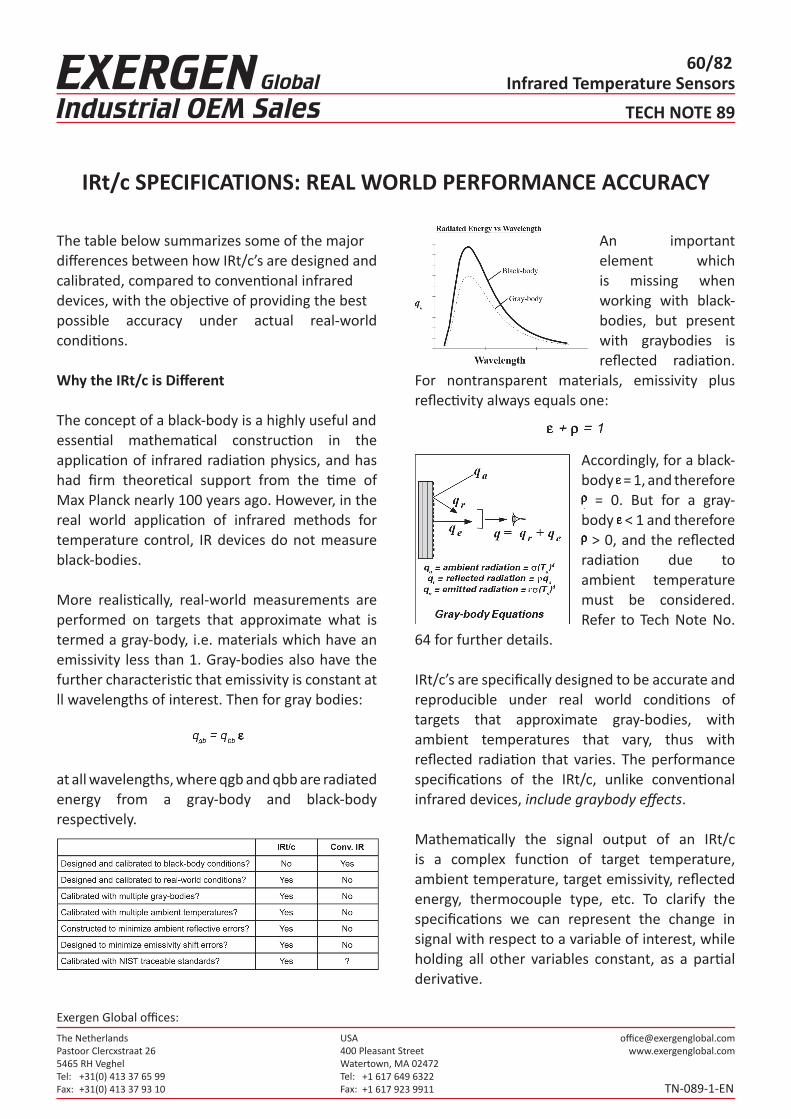
The NetherlandsPastoor Clercxstraat 265465 RH Veghel Tel: Fax:
+31(0) 413 37 65 99+31(0) 413 37 93 10
USA400 Pleasant StreetWatertown, MA 02472Tel: Fax:
+1 617 649 6322+1 617 923 9911
Exergen Global offices:
Infrared Temperature Sensors60/82
TECH NOTE 89
TN-089-1-EN
IRt/c SPECIFICATIONS: REAL WORLD PERFORMANCE ACCURACY
The table below summarizes some of the majordifferences between how IRt/c’s are designed andcalibrated, compared to conventional infrareddevices, with the objective of providing the bestpossible accuracy under actual real-world conditions.
Why the IRt/c is Different
The concept of a black-body is a highly useful andessential mathematical construction in the application of infrared radiation physics, and has had firm theoretical support from the time of Max Planck nearly 100 years ago. However, in the real world application of infrared methods for temperature control, IR devices do not measure black-bodies.
More realistically, real-world measurements are performed on targets that approximate what is termed a gray-body, i.e. materials which have an emissivity less than 1. Gray-bodies also have the further characteristic that emissivity is constant at ll wavelengths of interest. Then for gray bodies:
at all wavelengths, where qgb and qbb are radiatedenergy from a gray-body and black-body respectively.
An important element which is missing when working with black-bodies, but present with graybodies is reflected radiation.
For nontransparent materials, emissivity plus reflectivity always equals one:
Accordingly, for a black-body = 1, and therefore = 0. But for a gray-
body < 1 and therefore > 0, and the reflected
radiation due to ambient temperature must be considered. Refer to Tech Note No.
64 for further details.
IRt/c’s are specifically designed to be accurate andreproducible under real world conditions of targets that approximate gray-bodies, with ambient temperatures that vary, thus with reflected radiation that varies. The performance specifications of the IRt/c, unlike conventional infrared devices, include graybody effects.
Mathematically the signal output of an IRt/c is a complex function of target temperature, ambient temperature, target emissivity, reflected energy, thermocouple type, etc. To clarify the specifications we can represent the change in signal with respect to a variable of interest, while holding all other variables constant, as a partial derivative.

The NetherlandsPastoor Clercxstraat 265465 RH Veghel Tel: Fax:
+31(0) 413 37 65 99+31(0) 413 37 93 10
USA400 Pleasant StreetWatertown, MA 02472Tel: Fax:
+1 617 649 6322+1 617 923 9911
Exergen Global offices:
Infrared Temperature Sensors61/82
TECH NOTE 89
TN-089-1-EN
IRt/c SPECIFICATIONS: REAL WORLD PERFORMANCE ACCURACY
Ambient Temperature Coefficient Specification The variation in output signal with ambient temperature, which is the Ambient Temperature Coefficient specification, can be represented as below:where S is the output signal and Ta is the ambient
temperature. This equation describes the output of the IRt/c, including a gray-body assumption of emissivity = 0.9, and that the sensor itself is at thesame temperature as the environment.
What this means in practice is that when an IRt/c is installed and calibrated in place (Tech Notes No. 1, 64), the IRt/c body tends to change temperature with the ambient background that the target sees, then internally applies the correction required to reduce errors. Without this feature this error could be many times higher, and cause unwanted shifts in process control temperature.
For example, waterless printing processes require that the ink application roll to be temperature controlled in order to maintain high quality. If the temperature is to be controlled at 80°F (26.7°C), and the press enclosure can vary over the range 70 to 100°F (21.1 to 37.8°C) due to warm-up, weather, air ventilation, etc.; then a conventionalIR device will produce an error of about 3°F (1.7°C),while an IRt/c will produce an error of only 0.2°F (0.1°C). Thus, the IRt/c provides ten times more accurate control than the conventional device. To estimate the improvement in control accuracy produced by the IRt/c for a specific application, the following approximation can be applied:
Compensating for Emissivity Variations A common assumption for conventional IR thermometry is that emissivity is constant with changes in target surface temperature. Real materials do not have this characteristic. The average value for nonmetals for which the change in emissivity with respect to surface temperature has been reported, is approximately - 2% per 100°F target temperature change (- 3% per 100°C).

The NetherlandsPastoor Clercxstraat 265465 RH Veghel Tel: Fax:
+31(0) 413 37 65 99+31(0) 413 37 93 10
USA400 Pleasant StreetWatertown, MA 02472Tel: Fax:
+1 617 649 6322+1 617 923 9911
Exergen Global offices:
Infrared Temperature Sensors62/82
TECH NOTE 89
TN-089-1-EN
IRt/c SPECIFICATIONS: REAL WORLD PERFORMANCE ACCURACY
Applying the partial derivative mathematical formulation, the emissivity variation is:
Conventional IR misses this effect, and will causeprocess control errors.
The signal produced by the IR device is proportionalto the radiation emitted by the surface:
then the change in signal with respect to targetsurface temperature may be presented as follows:
Note that the conventional IR device loses one term of the signal change with respect to surface temperature. When the IR signal is converted to atemperature indication, the signal in the conventional device is linearized, whereas in the IRt/c the signal is unchanged.
Since real-world emissivity for most non-metal materials decreases with temperature, the constant emissivity assumption of conventional IR devices produces errors in readings that are not obvious to the typical IR user and can be highly misleading over a wide temperature range. The IRt/c, however, is specified for a useable specific temperature range, where the effect of emissivity change is accounted for in the linearity specification, and the user is confident that his process control will be accurate. Note that testing an IRt/c with a black body will not give the same linear range as a realbody.
A second effect on linear range is the effect of target surface temperature on ambient temperature, and therefore the reflected component of radiation to the sensor. As target temperature increases within a process, the increased radiation heat transfer to the surroundings will cause the target ambient radiant background to also increase in temperature.

The NetherlandsPastoor Clercxstraat 265465 RH Veghel Tel: Fax:
+31(0) 413 37 65 99+31(0) 413 37 93 10
USA400 Pleasant StreetWatertown, MA 02472Tel: Fax:
+1 617 649 6322+1 617 923 9911
Exergen Global offices:
Infrared Temperature Sensors63/82
TECH NOTE 89
TN-089-1-EN
IRt/c SPECIFICATIONS: REAL WORLD PERFORMANCE ACCURACY
For example, a laminating process that has severaltemperature control settings that depend on the material and feed speeds, may operate with targettemperatures that are 100°F (56°C) different. As the material changes temperature, the background radiation in the vicinity of the measurement will also change temperature, and influence the IR reading.
Accordingly, the variation in signal with target temperature has the additional component as follows:
Comparison to Standard ThermocouplesStandard thermocouples are generally specified as adhering to ASTM and ANSI specifications, hichprescribe a basic accuracy of ±2.2°C, or 0.75% of reading, whichever is higher2 . Likewise, IRt/c’s are also specified to be within the same ±2.2°C limits, or to the percentages stated in their specifications, whichever is higher.
However, it is important to note that when an IRt/c is calibrated to installation, this error disappears.
Repeatability and InterchangeabilityThe cardinal requirement for the IRt/c, as in any measuring device, is to repeat its calibration. The repeatability of IRt/c’s is specified at <0.1°C.
Interchangeability uncertainty from one device to another is 2% maximum, since each individual device is built and tested to conform to standardswith a ±1% tolerance, so is therefore able to produce a maximum of ±2% difference between any two devices. Typical interchangeability uncertainty, determined by test, is described statistically with standard deviation of approximately 0.5°C.
Summary1. The IRt/c is a different type of device compared
to conventional IR, since it is carefully designed and built to produce real world accuracy for temperature control, with some subtle features that make a significant improvement over conventional IR.
2. In-place calibration is always recommended, as it always is with any IR device due to uncertainties in emissivities and ambient temperature.
3. For OEM applications, or multiple same-use applications in a factory, once the initial system has been qualified and calibrated, IRt/c’s of the same model can be substituted without the necessity of recalibration.
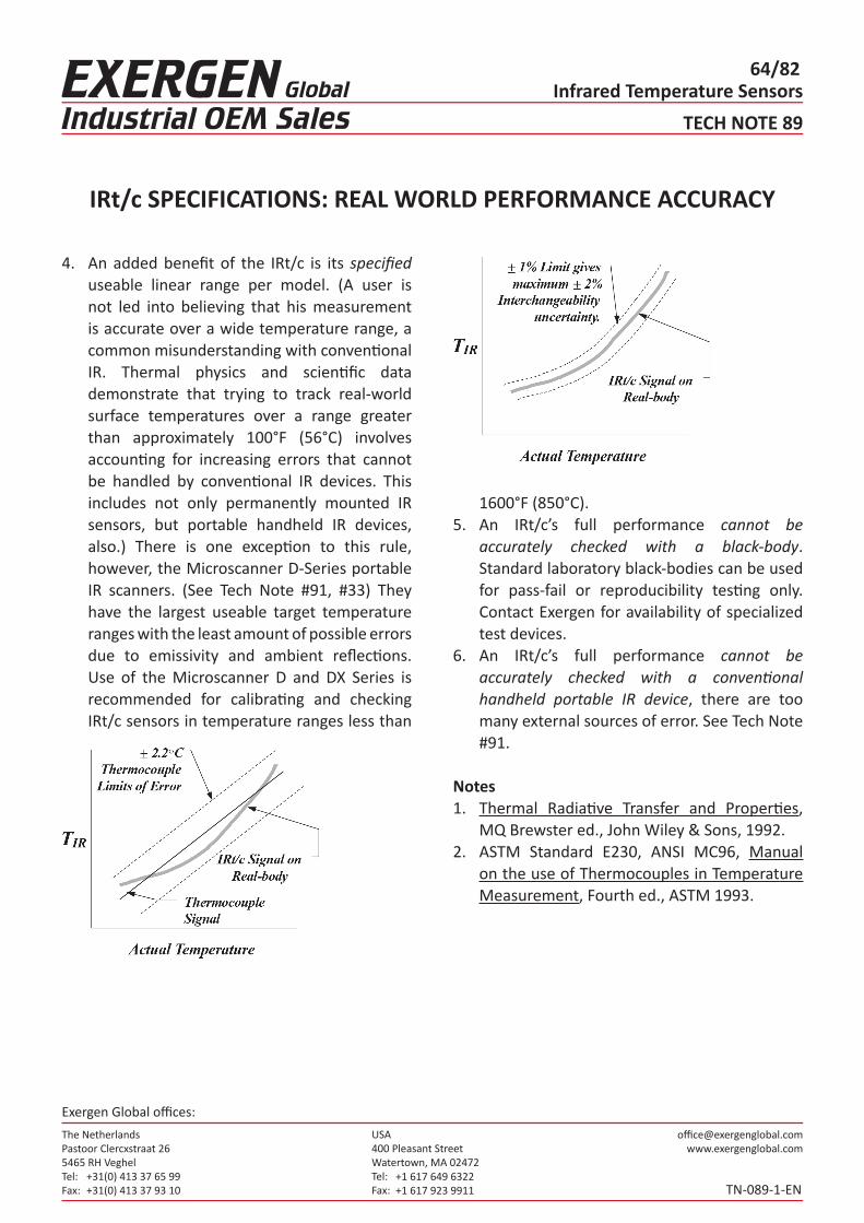
The NetherlandsPastoor Clercxstraat 265465 RH Veghel Tel: Fax:
+31(0) 413 37 65 99+31(0) 413 37 93 10
USA400 Pleasant StreetWatertown, MA 02472Tel: Fax:
+1 617 649 6322+1 617 923 9911
Exergen Global offices:
Infrared Temperature Sensors64/82
TECH NOTE 89
TN-089-1-EN
IRt/c SPECIFICATIONS: REAL WORLD PERFORMANCE ACCURACY
4. An added benefit of the IRt/c is its specified useable linear range per model. (A user is not led into believing that his measurement is accurate over a wide temperature range, a common misunderstanding with conventional IR. Thermal physics and scientific data demonstrate that trying to track real-world surface temperatures over a range greater than approximately 100°F (56°C) involves accounting for increasing errors that cannot be handled by conventional IR devices. This includes not only permanently mounted IR sensors, but portable handheld IR devices, also.) There is one exception to this rule, however, the Microscanner D-Series portable IR scanners. (See Tech Note #91, #33) They have the largest useable target temperature ranges with the least amount of possible errors due to emissivity and ambient reflections. Use of the Microscanner D and DX Series is recommended for calibrating and checking IRt/c sensors in temperature ranges less than
1600°F (850°C).5. An IRt/c’s full performance cannot be
accurately checked with a black-body. Standard laboratory black-bodies can be used for pass-fail or reproducibility testing only. Contact Exergen for availability of specialized test devices.
6. An IRt/c’s full performance cannot be accurately checked with a conventional handheld portable IR device, there are too many external sources of error. See Tech Note #91.
Notes1. Thermal Radiative Transfer and Properties,
MQ Brewster ed., John Wiley & Sons, 1992.2. ASTM Standard E230, ANSI MC96, Manual
on the use of Thermocouples in Temperature Measurement, Fourth ed., ASTM 1993.

The NetherlandsPastoor Clercxstraat 265465 RH Veghel Tel: Fax:
+31(0) 413 37 65 99+31(0) 413 37 93 10
USA400 Pleasant StreetWatertown, MA 02472Tel: Fax:
+1 617 649 6322+1 617 923 9911
Exergen Global offices:
Infrared Temperature Sensors65/82
TECH NOTE 90
TN-090-1-EN
IRt/c’S MORE ACCURATE THAN CONVENTIONAL IR IN REAL WORLD
A common misunderstanding amongst even experienced manufacturers and users of infrared temperature measurement equipment is that theaccuracy of temperature measurement is solely aspecification of the infrared device. This statement is correct only in the laboratory under controlled conditions with blackbody (emissivity = 1.0, reflectivity = 0) targets. In the real world, designs and specifications that are applicable in the laboratory can be misleading and sometimes outright incorrect. Following is a summary of the key points of accuracy in a comparison between the IRt/c and conventional IR (detailed mathematical development is presented in Tech Note No.89).
1. Real-world materials have emissivity < 1, and therefore have reflectivity > 0, which causes errors from varying background temperatures.
Even non-metals, with emissivity approximately 0.9 and reflectivity approximately 0.1, must reflect about 10% of the energy incident from the background ambient. This reflected energy, unrelated to the target temperature, is nevertheless measured by the infrared sensor, and therefore will introduce significant errors if the ambient temperature changes, as it does in the real world. Conventional IR devices, calibrated with blackbodies, usually ignore this effect, and thus are subject to the error. IRt/c’s are specifically designed and tested to include a correction for
this effect and thus improves their real-world accuracy.
2. Real-world materials have emissivities that change significantly with temperature, which causes significant errors even with perfect calibration and linearization.
Probably the most misleading concept in infrared thermometry is that emissivity is constant with varying temperature. Real-world materials have emissivity variations that range from an average of 2% per 100°F (60°C) temperature change for nonmetals, to 10% per 100°F (60°C) temperature change for some paints, and well over 100% per 100°F
(60°C) temperature change for some metals. Accordingly, accuracy of real-world temperature measurements should be considered valid only for a limited temperature range. Specifications of accuracy for conventional infrared devices specified over wide target temperature ranges are largely meaningless. (The sole exception is Exergen’s D-Series, due to its Automatic Emissivity Compensation System.)
IRt/c’s are specifically designed and tested to maintain very high accuracy over a limited temperature range, and specifically not specified to imply accuracy over a wide target temperature

The NetherlandsPastoor Clercxstraat 265465 RH Veghel Tel: Fax:
+31(0) 413 37 65 99+31(0) 413 37 93 10
USA400 Pleasant StreetWatertown, MA 02472Tel: Fax:
+1 617 649 6322+1 617 923 9911
Exergen Global offices:
Infrared Temperature Sensors66/82
and tested to standards that include elevated and variable ambient background temperatures, and real-world target materials that change emissivitywith temperature, thus maximizing the accuracy of temperature measurement and control.
1. Thermal Radiation Heat Transfer. R Siegel and JR Howell, ed., second edition, Hemisphere Publishing Corporation 1981.
TECH NOTE 90
TN-090-1-EN
IRt/c’S MORE ACCURATE THAN CONVENTIONAL IR IN REAL WORLD
range. For this reason IRt/c’s are offered in a variety of temperature range selections, each of which is optimized for a specific limited temperature range, which correctly reflects the realworld material characteristics, and maximizes the accuracy.
3. Real-world temperature control is most accurate if the IR sensor is designed, built, calibrated, and tested at factory conditions that are designed to reflect actual field conditions.
Conventional IR devices are designed, built, and tested to standards traditionally defined by blackbodies, which do not include the errors caused by reflected energy and emissivity variations of realworld materials. IRt/c’s are designed, built,

The NetherlandsPastoor Clercxstraat 265465 RH Veghel Tel: Fax:
+31(0) 413 37 65 99+31(0) 413 37 93 10
USA400 Pleasant StreetWatertown, MA 02472Tel: Fax:
+1 617 649 6322+1 617 923 9911
Exergen Global offices:
Infrared Temperature Sensors67/82
TECH NOTE 91
TN-091-1-EN
DISPOSABLE WINDOW
A not uncommon problem in some industrial environments, such as foundries, is maintaining optical cleanliness during washdown, or protectingthe lens from debris when air purge is impractical or insufficient. In addition, sometimes a barrier isnecessary between the process to be monitoredand the IRt/c.
Windows made of common materials such as glass, etc. will significantly attenuate infrared radiation from targets below about 1000°F (540°C) and arenot generally suitable for low temperature service.However, windows made of polyethylene will transmit very efficiently at all temperatures if they are thin enough. “Thin” means generally less than about 0.005 in. (0.1 mm).
An excellent material is a commonly available plastic wrap brand called Glad
Cling Wrap®, which can easily be wrapped around the IRt/c for cleanliness, or formed into a window. If the polyethylene is dirty or damaged, it can easily be replaced. With maximum temperature rating at about 212°F (100°C), this material can be used in many processes.
The transmission coefficient of such thin polyethylene is in the neighborhood of 90%, and therefore only a small recalibration of the readout device may be required. Other brands of plastic wrap are not recommended, unless you can confirm that they are made from polyethylene.
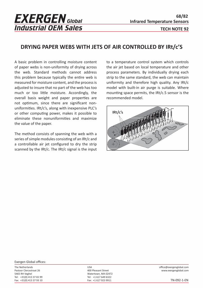
The NetherlandsPastoor Clercxstraat 265465 RH Veghel Tel: Fax:
+31(0) 413 37 65 99+31(0) 413 37 93 10
USA400 Pleasant StreetWatertown, MA 02472Tel: Fax:
+1 617 649 6322+1 617 923 9911
Exergen Global offices:
Infrared Temperature Sensors68/82
TECH NOTE 92
TN-092-1-EN
DRYING PAPER WEBS WITH JETS OF AIR CONTROLLED BY IRt/c’S
A basic problem in controlling moisture content of paper webs is non-uniformity of drying across the web. Standard methods cannot address this problem because typically the entire web is measured for moisture content, and the process isadjusted to insure that no part of the web has toomuch or too little moisture. Accordingly, the overall basis weight and paper properties are not optimum, since there are significant non-uniformities. IRt/c’s, along with inexpensive PLC’s or other computing power, makes it possible to eliminate these nonuniformities and maximize the value of the paper.
The method consists of spanning the web with a series of simple modules consisting of an IRt/c anda controllable air jet configured to dry the strip scanned by the IRt/c. The IRt/c signal is the input
to a temperature control system which controls the air jet based on local temperature and other process parameters. By individually drying each strip to the same standard, the web can maintain uniformity and therefore high quality. Any IRt/c model with built-in air purge is suitable. Where mounting space permits, the IRt/c.5 sensor is the recommended model.

The NetherlandsPastoor Clercxstraat 265465 RH Veghel Tel: Fax:
+31(0) 413 37 65 99+31(0) 413 37 93 10
USA400 Pleasant StreetWatertown, MA 02472Tel: Fax:
+1 617 649 6322+1 617 923 9911
Exergen Global offices:
Infrared Temperature Sensors69/82
TECH NOTE 96
TN-096-1-EN
IRt/c NON-CONTACT HEAT SEALING TEMPERATURECONTROL FOR PACKAGING MACHINERY (OEM & RETROFIT)
IRt/c infrared thermocouples can accurately control the temperature of rotating and moving stainless steel heaters common in the packaging industry, without touching the heaters.
Typically, uncoated stainless steel heaters are difficult for IR sensors to measure reliably because of reflected infrared signals that can change after after a heater surface is cleaned. The solution to this problem is simple:
Choose an unused location on the heaters, as close as possible to the surface you wish to measure. Mechanically mount a surface that is reliable for the IRt/c to measure.
There are at least two choices for a reliable infrared target surface that meet the needs of the packaging industry (able to withstand repeated daily cleanings, durable to provide years of service):

The NetherlandsPastoor Clercxstraat 265465 RH Veghel Tel: Fax:
+31(0) 413 37 65 99+31(0) 413 37 93 10
USA400 Pleasant StreetWatertown, MA 02472Tel: Fax:
+1 617 649 6322+1 617 923 9911
Exergen Global offices:
Infrared Temperature Sensors70/82
TECH NOTE 96
TN-096-1-EN
IRt/c NON-CONTACT HEAT SEALING TEMPERATURECONTROL FOR PACKAGING MACHINERY (OEM & RETROFIT)
1. Black, hard-anodized aluminum coated surfaceA black, hard-anodized aluminum hoop, ring, disk, or strip can be used. The surface must be “hard-anodized”. It can be mounted in place onto the steel heaters by using thermal epoxy, small screws, or othersuitable mounting methods.
This method is very good for “retrofit” situations. The IR target surface can be added right onto existingheaters.
2. Teflon coating, directly applied onto an unused part of the stainless steel heatersThis is an excellent choice for OEMs that already use teflon coatings in other parts of their machines. Simply have a teflon coating added to the best target area prior to installing the heaters.
“Open and Close” Heaters/Cutters - IRt/c controlFor jaw heaters/cutters that “open and close”, attach a small piece of coated metal to each heater head. This strip will come to the same temperature as the heater head as heat is conducted through the attachment point. The length of the strip should be just long enough so that the IRt/c sensor constantly looks at the strip during each “open and close” cycle giving a constant update of the temperature of the heaters.

The NetherlandsPastoor Clercxstraat 265465 RH Veghel Tel: Fax:
+31(0) 413 37 65 99+31(0) 413 37 93 10
USA400 Pleasant StreetWatertown, MA 02472Tel: Fax:
+1 617 649 6322+1 617 923 9911
Exergen Global offices:
Infrared Temperature Sensors71/82
TECH NOTE 96
TN-096-1-EN
IRt/c NON-CONTACT HEAT SEALING TEMPERATURECONTROL FOR PACKAGING MACHINERY (OEM & RETROFIT)
High Speed / High Performance
Heat Sealing
For Rotating Heaters and for Stationary Strip Heaters, an additional IRt/c can be added to control the sealing much more accurately as the machine begins to increase speed. The technique is as follows:
1. During start-up, control the heaters using the sensors directly measuring the heaters.2. As the machine speeds up, switch temperature measurement for the heater control system to a “run speed IRt/c”. This sensor is aimed directly at the actual fin seal, or lap seal, just after it is formed by the heaters. The “run speed IRt/c” will measure the actual seal temperature directly from the seal itself.
ExplanationBy measuring the actual temperature of the seal during high speed running, the heater control can be very precise, on the order of a few degrees. This will allow very tight tolerance heat sealing. This system will automatically reduce the following possible sources of high speed heat seal error:• Dirt build-up on the heater sealing surface
that impedes heat transfer to the seal• Packaging material changes in thickness• Changes in pressure applied to the sealThe control accuracy of this type of high performance system can also allow the use of a wider variety of packaging material compositions on the same machine.
IRt/c’s - Reliable, DurableThe rugged IRt/c sensors need no power supply, and are designed for years of trouble-free operation in industrial environments
No maintenance is required. The sealed IRt/csensors can even be steam-cleaned.
For “dusty” packaging environments, we recommend using the IRt/c.3X or other IRt/c models with built-in air-purge system. With a small amount of air, the sensor window will remain clear.
With the Exergen IRtc2132 temperature controllers, even small packaging machines can now benefit from reliable IRt/c temperature control for thermal sealing of packaging.
If additional technical assistance is needed, pleasecontact Exergen.

The NetherlandsPastoor Clercxstraat 265465 RH Veghel Tel: Fax:
+31(0) 413 37 65 99+31(0) 413 37 93 10
USA400 Pleasant StreetWatertown, MA 02472Tel: Fax:
+1 617 649 6322+1 617 923 9911
Exergen Global offices:
Infrared Temperature Sensors72/82
TECH NOTE 97
TN-097-1-EN
WEB DRYING - IRt/c’S FOR TRANSPARENT & REFLECTIVE FILMS, PAPER & TEXTILES (OEM & RETROFIT)
By using IRt/c sensor technology, a dramatic increase in high quality output of web processing can be achieved.• Increase drying speeds up to 20% or more• Reduce scrap up to 75% or more• Faster setup time when a new material is setup for processing• Greater variety of web materials to be processed on the same machine
BACKGROUNDA common problem in high speed manufacturing of packaging films, paper and textiles, is dryer oven control for high speed drying of adhesives, inks and coatings onto the material.
With transparent films, IR sensors tend to “see” right through the film. And the amount of “see through” can vary with the thickness and composition of the film. With metallic films, IR sensors tend to see mostly reflections. These reflections can vary due to the surface condition and composition of the metallic component of the particular film. Measuring the true temperature of transparent and reflective films is extremely difficult, even with expensive IR sensors with special filtering. Measuring the drying process, however, is easy with IRt/c sensors.
HOW IT WORKSThe key to measuring the drying process of webs is to use multiple IRt/c sensors to get a relative temperature profile. Multiple IRt/c sensors installed in the dryer, allow you to controll the drying process with the utmost precision.
What the IRt/c’s see: When a coating, even a thin coating, of glue, ink, or other finish is added to a surface, the coating itself becomes visible to IRt/c sensors. The drying characteristics of the coating can be seen even on reflective and transparent films. Even if it is a partial coating, the sensor can still “see” it. (The reason for this is that liquids, even very thin layers of liquids, are highly “emissive”, in other words they absorb and emit IR very well.)
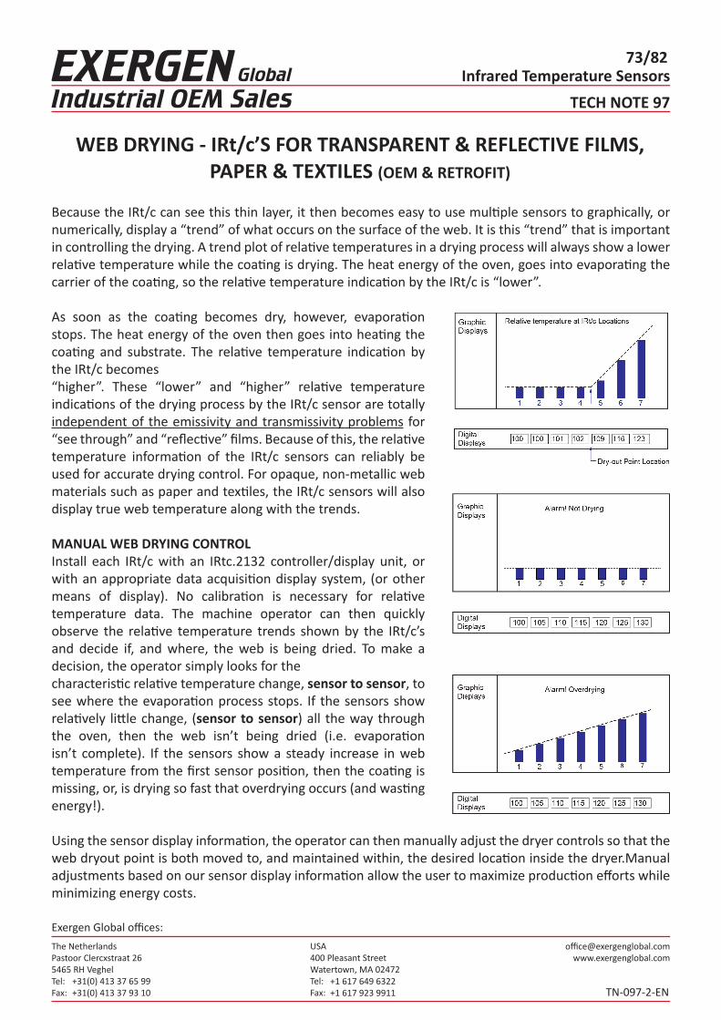
The NetherlandsPastoor Clercxstraat 265465 RH Veghel Tel: Fax:
+31(0) 413 37 65 99+31(0) 413 37 93 10
USA400 Pleasant StreetWatertown, MA 02472Tel: Fax:
+1 617 649 6322+1 617 923 9911
Exergen Global offices:
Infrared Temperature Sensors73/82
TECH NOTE 97
TN-097-2-EN
Because the IRt/c can see this thin layer, it then becomes easy to use multiple sensors to graphically, or numerically, display a “trend” of what occurs on the surface of the web. It is this “trend” that is important in controlling the drying. A trend plot of relative temperatures in a drying process will always show a lower relative temperature while the coating is drying. The heat energy of the oven, goes into evaporating the carrier of the coating, so the relative temperature indication by the IRt/c is “lower”.
As soon as the coating becomes dry, however, evaporation stops. The heat energy of the oven then goes into heating the coating and substrate. The relative temperature indication by the IRt/c becomes“higher”. These “lower” and “higher” relative temperature indications of the drying process by the IRt/c sensor are totally independent of the emissivity and transmissivity problems for “see through” and “reflective” films. Because of this, the relative temperature information of the IRt/c sensors can reliably be used for accurate drying control. For opaque, non-metallic web materials such as paper and textiles, the IRt/c sensors will also display true web temperature along with the trends.
MANUAL WEB DRYING CONTROLInstall each IRt/c with an IRtc.2132 controller/display unit, or with an appropriate data acquisition display system, (or other means of display). No calibration is necessary for relative temperature data. The machine operator can then quickly observe the relative temperature trends shown by the IRt/c’s and decide if, and where, the web is being dried. To make a decision, the operator simply looks for thecharacteristic relative temperature change, sensor to sensor, to see where the evaporation process stops. If the sensors show relatively little change, (sensor to sensor) all the way through the oven, then the web isn’t being dried (i.e. evaporation isn’t complete). If the sensors show a steady increase in web temperature from the first sensor position, then the coating is missing, or, is drying so fast that overdrying occurs (and wasting energy!).
Using the sensor display information, the operator can then manually adjust the dryer controls so that the web dryout point is both moved to, and maintained within, the desired location inside the dryer.Manual adjustments based on our sensor display information allow the user to maximize production efforts while minimizing energy costs.
WEB DRYING - IRt/c’S FOR TRANSPARENT & REFLECTIVE FILMS, PAPER & TEXTILES (OEM & RETROFIT)
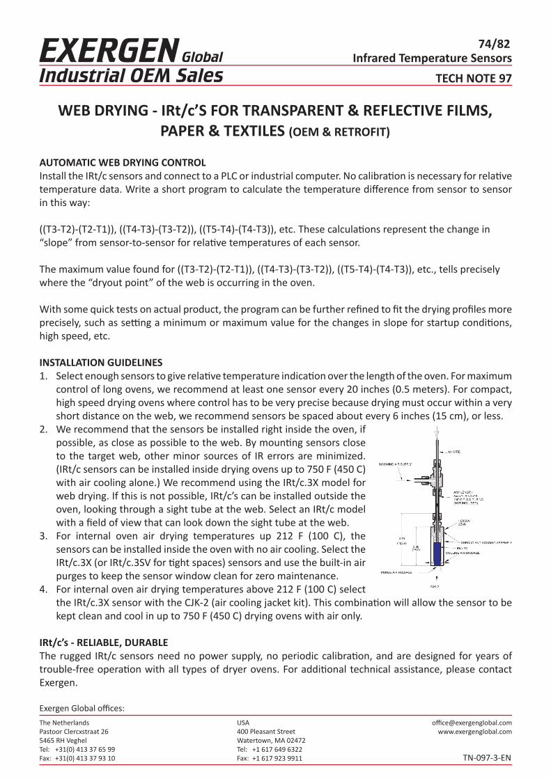
The NetherlandsPastoor Clercxstraat 265465 RH Veghel Tel: Fax:
+31(0) 413 37 65 99+31(0) 413 37 93 10
USA400 Pleasant StreetWatertown, MA 02472Tel: Fax:
+1 617 649 6322+1 617 923 9911
Exergen Global offices:
Infrared Temperature Sensors74/82
TECH NOTE 97
TN-097-3-EN
AUTOMATIC WEB DRYING CONTROLInstall the IRt/c sensors and connect to a PLC or industrial computer. No calibration is necessary for relative temperature data. Write a short program to calculate the temperature difference from sensor to sensor in this way:
((T3-T2)-(T2-T1)), ((T4-T3)-(T3-T2)), ((T5-T4)-(T4-T3)), etc. These calculations represent the change in“slope” from sensor-to-sensor for relative temperatures of each sensor.
The maximum value found for ((T3-T2)-(T2-T1)), ((T4-T3)-(T3-T2)), ((T5-T4)-(T4-T3)), etc., tells preciselywhere the “dryout point” of the web is occurring in the oven.
With some quick tests on actual product, the program can be further refined to fit the drying profiles more precisely, such as setting a minimum or maximum value for the changes in slope for startup conditions, high speed, etc.
INSTALLATION GUIDELINES1. Select enough sensors to give relative temperature indication over the length of the oven. For maximum
control of long ovens, we recommend at least one sensor every 20 inches (0.5 meters). For compact, high speed drying ovens where control has to be very precise because drying must occur within a very short distance on the web, we recommend sensors be spaced about every 6 inches (15 cm), or less.
2. We recommend that the sensors be installed right inside the oven, if possible, as close as possible to the web. By mounting sensors close to the target web, other minor sources of IR errors are minimized. (IRt/c sensors can be installed inside drying ovens up to 750 F (450 C) with air cooling alone.) We recommend using the IRt/c.3X model for web drying. If this is not possible, IRt/c’s can be installed outside the oven, looking through a sight tube at the web. Select an IRt/c model with a field of view that can look down the sight tube at the web.
3. For internal oven air drying temperatures up 212 F (100 C), the sensors can be installed inside the oven with no air cooling. Select the IRt/c.3X (or IRt/c.3SV for tight spaces) sensors and use the built-in air purges to keep the sensor window clean for zero maintenance.
4. For internal oven air drying temperatures above 212 F (100 C) select the IRt/c.3X sensor with the CJK-2 (air cooling jacket kit). This combination will allow the sensor to be kept clean and cool in up to 750 F (450 C) drying ovens with air only.
IRt/c’s - RELIABLE, DURABLEThe rugged IRt/c sensors need no power supply, no periodic calibration, and are designed for years of trouble-free operation with all types of dryer ovens. For additional technical assistance, please contact Exergen.
WEB DRYING - IRt/c’S FOR TRANSPARENT & REFLECTIVE FILMS, PAPER & TEXTILES (OEM & RETROFIT)

The NetherlandsPastoor Clercxstraat 265465 RH Veghel Tel: Fax:
+31(0) 413 37 65 99+31(0) 413 37 93 10
USA400 Pleasant StreetWatertown, MA 02472Tel: Fax:
+1 617 649 6322+1 617 923 9911
Exergen Global offices:
Infrared Temperature Sensors75/82
TECH NOTE 98
TN-098-1-EN
IRt/c’S -- USE WITH HEATED METAL ROLLERS / WEB PROCESSES TO INCREASE PRODUCTION (OEM & RETROFIT)
By using IRt/c sensor technology, a dramatic increase in high quality output of web processing can be achieved. Use the IRt/c’s with chrome-plated, stainless steel, or other uncoated metal rollers as well as with coated rollers. IRt/c systems enable the user to: • Increase throughput speeds up to 20%, or more, on the same machine • Reduce scrap up to 75% or more • Shorten set-up times • Process a greater variety of web materials on the same machine
Applications / Processes that would benefit from the use of IRt/c technology: • Textile Processing • Paper Processing • Opaque Films Processing • Any continuous web processes using heated (or cooled) rollers
Use of Exergen’s unique patented, non-contact infrared sensors solves past technical difficulties associated with temperature measurement of shiny, uncoated metal rollers (due to the high infrared reflectivity of the uncoated metal surfaces). Exergen has developed and tested a two stage approach to accurately measure and control the heat output of heated (or cooled) metal rollers using our IRt/c’s—even at very high speeds.
Stage 1: START-UP and STAND-BY Temperature ControlDuring start-up and stand-by conditions, the temperature of the heated roller will become fairly uniformthroughout the roller surfaces. Because of this, the temperature can be reliably measured at any convenient location on the surface, or the edge, of the rollers.So, for Stage 1, simply install an IRt/c so that it can see a reliable signal from the roller.
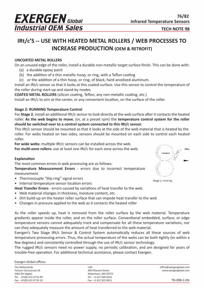
The NetherlandsPastoor Clercxstraat 265465 RH Veghel Tel: Fax:
+31(0) 413 37 65 99+31(0) 413 37 93 10
USA400 Pleasant StreetWatertown, MA 02472Tel: Fax:
+1 617 649 6322+1 617 923 9911
Exergen Global offices:
Infrared Temperature Sensors76/82
TECH NOTE 98
TN-098-2-EN
UNCOATED METAL ROLLERSOn an unused edge of the roller, install a durable non-metallic target surface finish. This can be done with: (a) a durable epoxy paint (b) the addition of a thin metallic hoop, or ring, with a Teflon coating (c) or the addition of a thin hoop, or ring, of black, hard-anodized aluminum.Install an IRt/c sensor so that it looks at this coated surface. Use this sensor to control the temperature of the roller during start-up and stand-by modesCOATED METAL ROLLERS (silicon coating, Teflon, any non-metallic coating, etc.)Install an IRt/c to aim at the center, or any convenient location, on the surface of the roller.
Stage 2: RUNNING Temperature ControlFor Stage 2, install an additional IRt/c sensor to look directly at the web surface after it contacts the heated roller. As the web begins to move, (or, at a preset rpm) the temperature control system for the roller should be switched over to a control system connected to this IRt/c sensor.This IRt/c sensor should be mounted so that it looks at the side of the web material that is heated by theroller. For webs heated on two sides, sensors should be mounted on each side to control each heated roller.For wide webs: multiple IRt/c sensors can be installed across the web.For multi-zone rollers: use at least one IRt/c for each zone across the web.
ExplanationThe most common errors in web processing are as follows:Temperature Measurement Errors - errors due to incorrect temperature measurement.• Thermocouple “Slip ring” signal errors• Internal temperature sensor location errorsHeat Transfer Errors - errors caused by variations of heat transfer to the web.• Web material changes in thickness, moisture content, etc.• Dirt build-up on the heater roller surface that can impede heat transfer to the web• Changes in pressure applied to the web as it contacts the heated roller
As the roller speeds up, heat is removed from the roller surface by the web material. Temperature gradients appear inside the roller, and on the roller surface. Conventional embedded, surface, or edge temperature sensors cannot adequately track and compensate for all these temperature variations, nor can they adequately measure the amount of heat transferred to the web material.Exergen’s Two Stage IRt/c Sensor & Control System automatically reduces all these sources of web temperature processing errors. Thus, the actual temperature of the webs can be both tightly (to within a few degrees) and consistently controlled through the use of IRt/c sensor technology.The rugged IRt/c sensors need no power supply, no periodic calibration, and are designed for years of trouble-free operation. For additional technical assistance, please contact Exergen.
IRt/c’S -- USE WITH HEATED METAL ROLLERS / WEB PROCESSES TO INCREASE PRODUCTION (OEM & RETROFIT)

The NetherlandsPastoor Clercxstraat 265465 RH Veghel Tel: Fax:
+31(0) 413 37 65 99+31(0) 413 37 93 10
USA400 Pleasant StreetWatertown, MA 02472Tel: Fax:
+1 617 649 6322+1 617 923 9911
Exergen Global offices:
Infrared Temperature Sensors77/82
TECH NOTE 100
TN-100-1-EN
ACCURATE TEMPERATURE CONTROL IN WATERLESS PRINTING WITH IRt/c SENSORS: HOW TO INCREASE PRINTING SPEED
By Francesco Pompei, Exergen Corporation
At the heart of waterless printing is the requirement for accurate temperature control of the ink roller system due to the importance of maintaining proper viscosity. A significant barrier to improvement in the quality of ink temperature control for waterless printing systems is the delay caused by the mass of the roller, especially when increasing speeds.
Water-cooled systems are particularly subject to this delay since the roll is cooled from the inside, and the entire mass of the roll must change temperature in order to control the surface, where the ink properties are, of course, determined. Air-cooled systems are less influenced by the delay, but still require an optimal control strategy to maximize speed.
At the heart of the temperature control are non-contact infrared sensors that are designed specifically for the waterless printing application. One such model is the IRt/c-WP series from Exergen, which is the most accurate available. The discussions below use these sensors.
Water-Cooled Systems
A change in temperature on the cooled roller outside surface Ts, will be sensed by the IRt/c infrared sensor within a tenth of a second, and the correction to the water cooling temperature Tw will occur within a few seconds. However, the entire mass of the roll must change temperature from the inside-out before the surface can change and thus correct the temperature of the ink – a process requiring several minutes. The several minutes that the temperature is incorrect may cause reduced quality printing, and thus prevent operation at higher speeds.
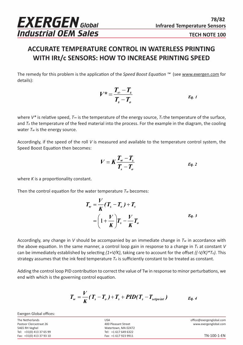
The NetherlandsPastoor Clercxstraat 265465 RH Veghel Tel: Fax:
+31(0) 413 37 65 99+31(0) 413 37 93 10
USA400 Pleasant StreetWatertown, MA 02472Tel: Fax:
+1 617 649 6322+1 617 923 9911
Exergen Global offices:
Infrared Temperature Sensors78/82
TECH NOTE 100
TN-100-1-EN
The remedy for this problem is the application of the Speed Boost Equation ™ (see www.exergen.com for details):
where V* is relative speed, T∞ is the temperature of the energy source, Ts the temperature of the surface, and To the temperature of the feed material into the process. For the example in the diagram, the cooling water Tw is the energy source.
Accordingly, if the speed of the roll V is measured and available to the temperature control system, the Speed Boost Equation then becomes:
where K is a proportionality constant.
Then the control equation for the water temperature Tw becomes:
Accordingly, any change in V should be accompanied by an immediate change in Tw in accordance with the above equation. In the same manner, a control loop gain in response to a change in Ts at constant V can be immediately established by selecting (1+V/K), taking care to account for the offset ((-V/K)*To). This strategy assumes that the ink feed temperature To is sufficiently constant to be treated as constant.
Adding the control loop PID contribution to correct the value of Tw in response to minor perturbations, we end with which is the governing control equation.
ACCURATE TEMPERATURE CONTROL IN WATERLESS PRINTING WITH IRt/c SENSORS: HOW TO INCREASE PRINTING SPEED

The NetherlandsPastoor Clercxstraat 265465 RH Veghel Tel: Fax:
+31(0) 413 37 65 99+31(0) 413 37 93 10
USA400 Pleasant StreetWatertown, MA 02472Tel: Fax:
+1 617 649 6322+1 617 923 9911
Exergen Global offices:
Infrared Temperature Sensors79/82
TECH NOTE 100
TN-100-1-EN
Variable Feed Roll Temperature To
As is the case in many high performance installations, the feed roll temperature is not always constant, since friction from the rolls will gradually warm the rolls. Accordingly, to further improve performance, the addition of a second IRt/c is recommended to monitor the feed roll temperature To. With this additional sensor, equation 4 is again employed, but To is treated as variable and its value measured by a second IRt/c. This measure is recommended when the quantity in the denominator of equation 2 (Ts-To) is less than ~ 10 C, and is greater than the quantity in the numerator (Tw-Ts). This situation will exist as the speed V is increased and the heat transfer characteristics of the roll are improved.
Maximal Speed and Performance Strategy
For maximum print speeds at maximum quality, the quantities (Tw-Ts) and (Ts-To) must be accurately controlled under all conditions. The PID feedback control is not sufficient since at maximum speeds the feedback requires significant time to respond due to the thermal lag of the roller from the inside to the outer surface, and will produce ink temperature errors and thus poor quality.
The IRt/c sensors provide an elegantly simple and robust method of achieving the maximal accuracy by employing their inherent thermocouple character. Rewriting equation 4:
ACCURATE TEMPERATURE CONTROL IN WATERLESS PRINTING WITH IRt/c SENSORS: HOW TO INCREASE PRINTING SPEED

The NetherlandsPastoor Clercxstraat 265465 RH Veghel Tel: Fax:
+31(0) 413 37 65 99+31(0) 413 37 93 10
USA400 Pleasant StreetWatertown, MA 02472Tel: Fax:
+1 617 649 6322+1 617 923 9911
Exergen Global offices:
Infrared Temperature Sensors80/82
TECH NOTE 100
TN-100-1-EN
we see that the critical temperatures for control are the differences (Tw-Ts) and (Ts-To), with the PID feedback a small trim on the setpoint of Ts. From basic thermocouple characteristics we can directly measure these temperature differences with accuracy of order 0.1C by simply wiring IRt/c’s differentially as common thermocouples.
Further, the feed water temperature Tw may be measured by an ordinary immersion thermocouple, then wired in series with an IRt/c monitoring Ts to produce a direct signal for (Tw-Ts).
The end result from the application of the Speed Boost Equation is balanced cooling input that correctly adjusts the flow of heat to maintain consistent balance in the heat into and out of the roll surface. With this balance, temperature control is maintained accurately, and speed may be increased to maximal values permissible by the press without loss of quality.
Air-Cooled Systems
Air cooling systems have the significant advantage that there is less delay in response to a cooling load change, since only the immediate surface must change temperature. However, the roll doesrequire re-establishment of distribution of temperature around the roll as conditions change, especially speed, and therefore optimal control requires the Speed Boost method.
ACCURATE TEMPERATURE CONTROL IN WATERLESS PRINTING WITH IRt/c SENSORS: HOW TO INCREASE PRINTING SPEED

The NetherlandsPastoor Clercxstraat 265465 RH Veghel Tel: Fax:
+31(0) 413 37 65 99+31(0) 413 37 93 10
USA400 Pleasant StreetWatertown, MA 02472Tel: Fax:
+1 617 649 6322+1 617 923 9911
Exergen Global offices:
Infrared Temperature Sensors81/82
TECH NOTE 100
TN-100-1-EN
Applying again eq. 1,
and referring to the temperatures in Figure 6, the equation can be re-written as
where K is the proportionality constant.
Then the control equation for the air temperature Ta becomes:
Accordingly, any change in V should be accompanied by an immediate change in air temperature Ta in accordance with the above equation.
Adding the control loop PID contribution to correct the value of Ta in response to minor perturbations, we end with
which is a form of governing control equation that can be applied. The differential IRt/c wiring illustrated in Figures 4 and 5 is the method of choice to assure highest possible performance in controlling for quality and speed. By adding the air temperature Ta as a thermocouple, and a second IRt/c for Ts, then the governing equation becomes
and the performance is the highest possible speed with the best possible quality.
ACCURATE TEMPERATURE CONTROL IN WATERLESS PRINTING WITH IRt/c SENSORS: HOW TO INCREASE PRINTING SPEED

The NetherlandsPastoor Clercxstraat 265465 RH Veghel Tel: Fax:
+31(0) 413 37 65 99+31(0) 413 37 93 10
USA400 Pleasant StreetWatertown, MA 02472Tel: Fax:
+1 617 649 6322+1 617 923 9911
Exergen Global offices: