exercise ship design introduction container ships - über · pdf file ·...
TRANSCRIPT

Institute ofShip Design and Ship Safety
Exercise
Ship Design
Introduction Container Ships
Prof. Dr.-Ing. Stefan Krüger
Dipl.-Ing. Philip Augener
Dipl.-Ing. Arne Falkenhorst
Exercise Ship Design 22. Oktober 2014
Exercise 1Introduction Container Ships
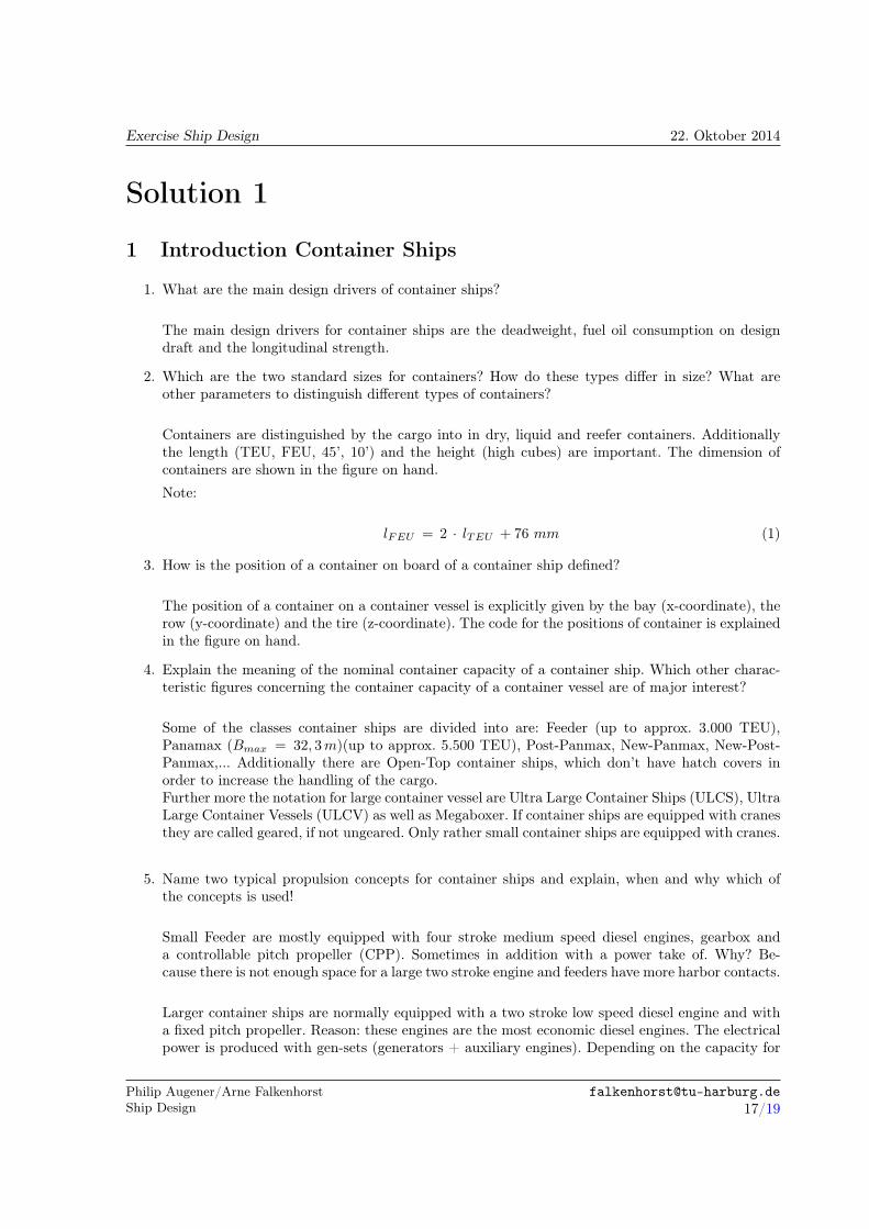
1. What are the main design drivers of container ships?
2. Which are the two standard sizes for containers? How do these types differ in size? What are otherparameters to distinguish different types of containers?
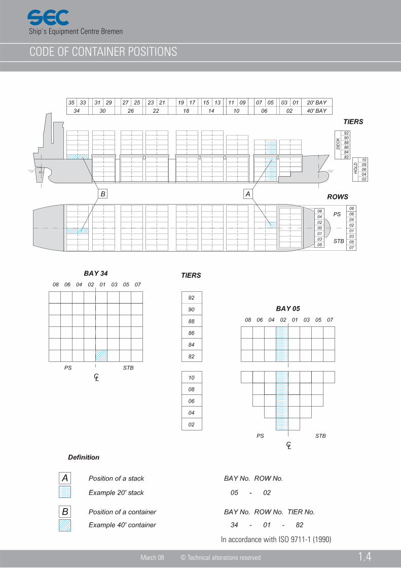
3. How is the position of a container on board of a container ship defined?
4. Explain the meaning of the nominal container capacity of a container ship. Which other charac-teristic figures concerning the container capacity of a container vessel are of major interest?
5. Name two typical propulsion concepts for container ships and explain, when and why which of theconcepts is used!
6. State the intact stability criteria that are applicable for container ships? In which code do youfind them?
7. What specialty do you have to take into account for container ships regarding the weather criterion?
8. Which damage stability regulation is valid for new-buildings of container ships in the moment? Inwhich code do you find it?
9. Which limiting stability curves result from the above mentioned stability criteria and over whichquantity are these curves connected to each other?
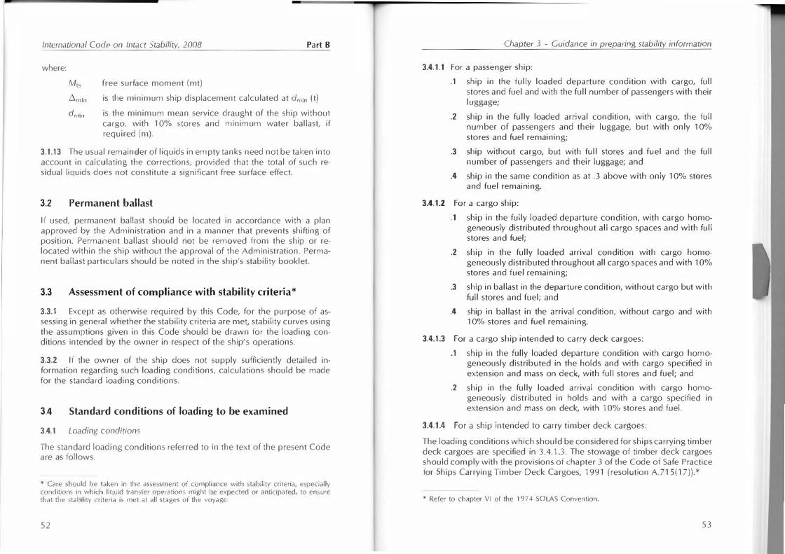
10. Which are the standard loading conditions representing the minimum number of loading conditi-ons, that have to be evaluated for stability reasons? In which code do you find the definitions?
11. You have received a short version of the technical specification of a container vessel as well as adiagram with the limiting stability curves of the ship. Bring together the four loading conditionsdefined in the technical specification with the dots in the diagram.
12. Which is the limiting criterion regarding the stack height of containers in the holds? Which ad-ditional criterion has to be considered regarding the stack height for containers on deck and inwhich code do you find this?
Philip Augener/Arne FalkenhorstShip Design

Container dimensions
Ship`s Equipment Centre Bremen GmbH
May 2011 © Technical alterations reserved 1.6
In accordance withISO 668 (1995)
Ship`s Equipment Centre Bremen
CODE OF CONTAINER POSITIONS
March 08 © Technical alterations reserved 1.4
In accordance with ISO 9711-1 (1990)

International Code on Intact Stability, 2008 Part A
2.2 Criteria regarding righting lever curve properties
2.2.1 The area under the righting lever curve (GZ curve) shall not be less than 0.055 metre-radians up to q> = 30 angle of heel and not less than 0.09 metre-radians up to <p = 40 or the angle of down-flooding c.p1* if this angle is less than 40 . Additionally, the area under the righting lever curve (GZ curve) between the angles of heel of 30 and 40 or between 30 and q>,, if this angle is less than 40 , shall not be less than 0.03 metre-radians.
2.2.2 The righting lever (GZ) shall be at least 0.2 m at an angle of heel equal to or greater than 30 .
2.2.3 The maximum righting lever shall occur at an angle of heel not less than 25 . If this is not practicable, alternative criteria, based on an equivalent level of safety, 1' may be applied subject to the approval of the Administration.
2.2.4 The initial metacentric height GM0 shall not be less than 0.15 m.
2.3 Severe wind and rolling criterion (weather criterion)
2.3.1 The ability of a ship to withstand the combined effects of beam wind and rolling shall be demonstrated, with reference to figure 2.3.1, as follows:
.1 the ship is subjected to a steady wind pressure acting perpendicular to the ship's centreline which results in a steady wind heeling lever Uwt );
.2 from the resultant angle of equilibrium (q>0), the ship is assumed to roll owing to wave action to an angle of roll (<p1) to windward. The angle of heel under action of steady wind (c.p0) should not exceed 16 or 80% of the angle of deck edge immersion, whichever is less;
.3 the ship is then subjected to a gust wind pressure which results in a gust wind heeling lever (l,d; and
* �p, is an an..:lt• or lw<•l ilt which openings in the hull, superstructures or deck-houses which c,1nnoL be closed wcathrrtight immerse. In applying this criterion, small openings through which prO)Irl'S�iw llooding comnot take place need not be considered as open.
t Refer to thl• (xpl.ln,)!ory Notes to the International Code on Intact Stabilily, 2008 (MSC.l/ Circ.l.?81) (�Cl' p.1gC I 19 or this publicdtion).
20
Chapter 2 - General criteria
.4 under these circumstances, area b shall be equal to or greater than area a, as indicated in figure 2.3.1 below:
q>,
<p2
Angle of heel
Figure 2.3.1 - Severe wind and rolling
where the angles in figure 2.3.1 are defined as follows:
q>0 angle of heel under action of stea�y wind
fwo
<p, angle of roll to windward due to wave action (see 2.3.1 .2, 2.3.4 and second footnote on page 20)
q>2 = angle of down-nooding (<pr) or 50° or q>0 whichever is least,
where:
<J>r = angle of heel at which openings in the hull, superstructures or deck-houses which cannot be closed weathertight immerse. In applying this criterion, small openings through which progressive flooding cannot take place need not be considered as open.
<r>c angle of second intercept between wind heeling lever lw2 and GZ curves.
21


13,5
14,5
15,5
16,5
17,5
18,5
19,5
20,5
21,5
22,5
37500 47850 58200 68550 78900 89250 99600 109950 120300 130650 141000 151350
KG
[m]
Displacement [t]
KG_Max_Intakt KG_Max_Wetter KG_Max_Leck
International Code on Intact Stability, 2008 Part B
where:
free surface moment (mt)
is the minimum ship displacement calculated at dmin (t)
dmin is the minimum mean service draught of the ship without cargo, with 10% stores and minimum water ballast, if required (m).
3.1.13 The usual remainder of liquids in empty tanks need not be taken into account in calculating the corrections, provided that the total of such residual liquids does not constitute a significant free surface effect.
3.2 Permanent ballast
If used, permanent ballast should be located in accordance with a plan approved by the Administration and in a manner that prevents shifting of position. Permanent ballast should not be removed from the ship or relocated within the ship without the approval of the Administration. Permanent ballast particulars should be noted in the ship's stability booklet.
3.3 Assessment of compliance with stability criteria*
3.3.1 Except as otherwise required by this Code, for the purpose of assessing in general whether the stability criteria are met, stability curves using the assumptions given in this Code should be drawn for the loading conditions intended by the owner in respect of the ship's operations.
3.3.2 If the owner of the ship does not supply sufficiently detailed information regarding such loading conditions, calculations should be made for the standard loading conditions.
3.4 Standard conditions of loading to be examined
3.4.1 Loading conditions
The standard loading conditions referred to in the text of the present Code are as follows.
* Care should be taken in the assessment oi compliance with stability criteria, especially conditions in whicn liquid transfer operations might be expected or anticipated, to ensure that the stability criteria is met at all stages oi the voyage.
52
Chapter 3 - Guidance in preparing stability information
3.4.1.1 For a passenger ship:
.1 ship in the fully loaded departure condition with cargo, full stores and fuel and with the full number of passengers with their luggage;
.2 ship in the fully loaded arrival condition, with cargo, the full number of passengers and their luggage, but with only 10% stores and fuel remaining;
.3 ship without cargo, but with full stores and fuel and the full number of passengers and their luggage; and
.4 ship in the same condition as at .3 above with only 1 0% stores and fuel remaining.
3.4.1.2 For a cargo ship:
.1 ship in the fully loaded departure condition, with cargo homogeneously distributed throughout all cargo spaces and with full stores and fuel;
.2 ship in the fully loaded arrival condition with cargo homogeneously distributed throughout all cargo spaces and with 1 0% stores and fuel remaining;
.3 ship in ballast in the departure condition, without cargo but with full stores and fuel; and
.4 ship in ballast in the arrival condition, without cargo and with 10% stores and fuel remaining.
3.4.1.3 For a cargo ship intended to carry deck cargoes:
.1 ship in the fully loaded departure condition with cargo homogeneously distributed in the holds and with cargo specified in extension and mass on deck, with full stores and fuel; and
.2 ship in the fully loaded arrival condition with cargo homogeneously distributed in holds and with a cargo specified in extension and mass on deck, with 1 0% stores and fuel.
3.4.1.4 For a ship intended to carry timber deck cargoes:
The loading conditions which should be considered for ships carrying timber deck cargoes are specified in 3.4.1.3. The stowage of timber deck cargoes should comply with the provisions of chapter 3 of the Code of Safe Practice for Ships Carrying Timber Deck Cargoes, 1991 (resolution A.715( 17)). *
* Refer to chapter VI of the 1974 SOLAS Convention.
53

Preliminary Outline of Shipowner's Requirements for Concept Design
Type Container Vessel
Route 1 Northern Europe, Asia
Range 19.000nmat service speed
Specifies bunker capacityOil fuel tank protection acc. to MARPOL 73/78 Annex I New Regulation 12A
Stability Standard intact: IMO 749, leak: acc. to SOLAS
keel laying Jan. 2009
Speed Service 24.2 kn Service Speed at design condition, BF3, 85%MCR
Indicative Main Dimensions
Main dimensions to be optimized with respect to economy (building and operational cost) for given capacity and operational requirements, including the requested stability standards
LoA 350.0m max
Lpp - to be optimized
B 42.8m max
T (design) 13.0m
T (full scantling) 15.0m
Deadweight 112,000t at full scantling draft
Capacities -Payload-
Container 9,450 TEU geometric spaces
6,950 min. 14t homogeneous load (VCG at 45% of cont. height)
Reefer 700 10kW/reefer, utilisation factor: 0.8
Capacities-Bunker & Stores-
specified by range
Capacities-Water Ballast-
• As needed to comply with effectual rules and criteria
• Overall capacity to be minimized
Load Case 1 (Design Condition)
Design Condition, Departure
• max. number of TEU (12t homog. load, VCG at 45% of height)
• 100% bunker & stores• design draft (even keel, no heel)• ballast water as needed according to
effectual stability criteria (required amount to be minimized)
Postanschrift: Telefon: E-mail:Prof. Dr.-Ing. Stefan Krüger ++49 (40) 428 78 - 6105 [email protected]. für Entwerfen von Schiffen und Schiffssicherheit Fax: www.ssi.tu-harburg.deSchwarzenbergstraße 95, Gebäude C ++49 (40) 428 78 - 6139D - 21073 Hamburg
Input Specification Cont. Vessel

Load Case 2 (Arrival) Design Condition Arrival
• 100% Payload (see above)• 10% bunker holding tanks• 100% service tanks• preferably even keel and no heel• ballast water as needed according to
effectual stability criteria (see above)
Load Case 3 Ballast Condition • 0% payload• 10% bunker holding tanks• 100% service and settling tanks• ballast water as needed (least trim
possible) according to effectual stability criteria (see above)
Interior Design
Crew Cabins 25 fixed, additional rooms as required (storage spaces, mess, suez & repair crew, pilot's cabin, owner's cabin etc.)
Passenger Cabins -
Crew Number 25+6 Suez Crew
Public Spaces separated day rooms for officers and crew, officer's laundry rm, etc.
Additional Equipments
none
Manouevring Devices
Bowthruster 1 x 2600kW
Vessels of Comparison
Lines 8200TEU
GA-Plan 9100TEU
Lightshipweight 9100TEU
Postanschrift: Telefon: E-mail:Prof. Dr.-Ing. Stefan Krüger ++49 (40) 428 78 - 6105 [email protected]. für Entwerfen von Schiffen und Schiffssicherheit Fax: www.ssi.tu-harburg.deSchwarzenbergstraße 95, Gebäude C ++49 (40) 428 78 - 6139D - 21073 Hamburg

13,5
14,5
15,5
16,5
17,5
18,5
19,5
20,5
21,5
22,5
37500 47850 58200 68550 78900 89250 99600 109950 120300 130650 141000 151350
KG
[m]
Displacement [t]
KG_Max_Intakt KG_Max_Wetter KG_Max_Leck Ladefälle

Chapter V: Sc!fcty (�{ navigaUon Regulation 22
.3 Administrations may exempt cargo ships fi.·om the application of tht· n:quircments of subparagraphs . 1 and .2 when such ships will be taken permanently out of service within rvvo years after the implementation date specified in subp:lr:'lf,rraphs . I and .2 above.
3 Administrations may exempt ships, other than ro-ro passenger ships, constmctcd before 1 July 2002 from being fitted with a VDR where it can be demonstrated that interfacing a VDR with the exi�ting equipment on the ship is unreasonable and impracticable.
Regulation 21 b1tematimwl Code of Sig11als and IAMSAR Ma1111al
1 All ships which, in accordance with the present Convention, arc required to carry a radio installation shall carry the lntemational Code ofSignals as may be amended by the Organization. The Code shall also be carried by any other ship which, in the opinion of the Administr:'ltion. has a need to me it.
2 All ships shall carry an up-to-date copy of Volume III of the International Aeron::\lltical and Maritime Search and Rescue (IAMSAR) Manual.
Regulation 22 Navigatio11 bridge visibility
1 Ships of not less than 55 m in length, as defined in regulation 2.4, constructed on or after 1 July 1998, shall meet the following requirements:
.1 The view of the sea surface from the conning position shall not be obscured by more than two ship lengths, or 500 m, whichever is Jess, forward of the bow to 10° on either side under all conditions of draught, trim and deck cargo;
.2 No blind sector, caused by cargo, cargo gear or other obstmctions outside of the wheelhouse forward of the beam which obstructs the view of the sea smface as seen from the conning position, shall exceed 10°. The total arc of blind sectors shall not exceed 20°. The clear sectors between blind sectors shall be at least 5°. However, in the view described in .1, each individual blind sector shall not exceed 5°;
.3 The horizontal field of vision from the conning position shall extend over an arc of not less than 225°, that is from right ahead to not less than 22S abaft the beam on either side of the ship;
.4 From each bridge wing, the horizontal field of vision shall extend over an arc of at least 225", that is from at least 45° on the opposite bow through right ahead and then from right ahead to right astern through 180" on the same side of the ship;
.5 From the main steering position, the horizontal field of vision shall extend over an arc from right ahead to at least 60° on each side of the ship:
.6 The ship's side shall be visible from the bridge wing;
.7 The height of the lower edge of the navigation bridge fi·ont windows above the bridge deck shall be kept as low a� possible. In no case shall the lower edge present an obstruction to the forward vie\v as described in this regulation;
.8 The upper edge of the navigation bridge front windows shaH allow a forward view of the horizon, for a person with a height of eye of 1,800 mm above the bridge deck at the conning position, when the ship is pitching in heavy seas. The Administration. if satisfied that a I ,ROO mm height of eye is unreasonable <md impractical, may allow reduction of the height of eye but not to kss than 1 ,600 mm;
.9 Windows shaU meet the following requirements:
.9.1 To help avoid reflections. the bridge front windo\\'s <;hall be inclined fi·om the vertical plane top out. at an angle of not less than 10 and nor more than 25 ;
.9.2 Framing between navigation bridge windo\\·� shall be kept to a minimum and not be imlallcd immediatdy forward of any work station;
.9.3 Polarized and tinted windows sball not be fitted:

Permissible forces on containers
Ship`s Equipment Centre Bremen GmbH
May 2011 © Technical alterations reserved1.11
Lashing loads at corner casting
Acting parallel to front and sideface at top and bottom corner fitting.
In accordance with ISO 1161 (1984)

MAIN PARTICULARS TANK CAPACITIES CONTAINER CAPACITIESLength over all appr. 151,72 m Heavy fuel oil appr. 1.012 m³ max. number of containers ( IMO )Length betw. perp. 142,00 m Marine diesel oil appr. 117 m³ 20'-cont.Breadth 23,40 m Lubricating oil appr. 37 m³ On deck 714 TEUDepth to Main Deck 9,50 m Fresh water appr. 153 m³ In cargo holds 322 TEUDepth to Upper Deck 11,75 m Ballast/heeling water appr. 5.870 m³ Total 1036 TEUDraught, design 7,60 m Cruising range appr. 10.000 nm 40'-reeferDraught, maximum 8,00 m On deck appr. 136 FEUDeadweight (D = 8,00m) appr. 13.000 t MAIN ENGINE In cargo hold appr. 114 FEUSpeed (D = 7,45m/7,75m) appr. 19,0 kn MAK (opt. MAN, Wärtsilä) 9 M 43 Total appr. 250 FEU(100% MCR without SG) MCR 9000 kW / 500 rpm Rows max. in holds/on hatches 8/9Class: BV + 1 HULL + MACH Single gearbox vertical type with PTO for Tiers max. in holds/on hatches 4/6
INWATER SURVEY AUT-UMS Shaft alternator (1700 kW )ICE IA CONTAINER SHIP Variable-pitch propeller Stability (14t/TEU homog. at 45%)DANGEROUS CARGO Bow thruster 800 kW 745 TEUUNRESTRICTED NAVIGATION
Gross Tonnage appr. 10.585 GT POWER SUPPLYNet Tonnage appr. 5.372 NT Diesel Generators 3 x 550 kW el.Complement staff 16+2 Shaft Generator (const. speed) 1 x 1700 kW el. Reefer Container 257 FEU
pilot 1 Emergency Generator 1 x 315 kW el. Reefer Stowage (114 Hold / 136 Deck)
SSW Super 1000SSW Schichau Seebeck Shipyard GmbHRiedemannstr.1 - D-27572 BremerhavenTel: +49 471 39 20 Fax: +49 471 39 22 39E-Mail: [email protected] www.schichau-seebeck-shipyard.com
draught = 8,0 m appr.
MainData_Super1000M-Ice.xls 10.07.2006


Exercise Ship Design 22. Oktober 2014
Solution 1
1 Introduction Container Ships
1. What are the main design drivers of container ships?
The main design drivers for container ships are the deadweight, fuel oil consumption on designdraft and the longitudinal strength.
2. Which are the two standard sizes for containers? How do these types differ in size? What areother parameters to distinguish different types of containers?
Containers are distinguished by the cargo into in dry, liquid and reefer containers. Additionallythe length (TEU, FEU, 45’, 10’) and the height (high cubes) are important. The dimension ofcontainers are shown in the figure on hand.
Note:
lFEU = 2 · lTEU + 76 mm (1)
3. How is the position of a container on board of a container ship defined?
The position of a container on a container vessel is explicitly given by the bay (x-coordinate), therow (y-coordinate) and the tire (z-coordinate). The code for the positions of container is explainedin the figure on hand.
4. Explain the meaning of the nominal container capacity of a container ship. Which other charac-teristic figures concerning the container capacity of a container vessel are of major interest?
Some of the classes container ships are divided into are: Feeder (up to approx. 3.000 TEU),Panamax (Bmax = 32, 3m)(up to approx. 5.500 TEU), Post-Panmax, New-Panmax, New-Post-Panmax,... Additionally there are Open-Top container ships, which don’t have hatch covers inorder to increase the handling of the cargo.Further more the notation for large container vessel are Ultra Large Container Ships (ULCS), UltraLarge Container Vessels (ULCV) as well as Megaboxer. If container ships are equipped with cranesthey are called geared, if not ungeared. Only rather small container ships are equipped with cranes.
5. Name two typical propulsion concepts for container ships and explain, when and why which ofthe concepts is used!
Small Feeder are mostly equipped with four stroke medium speed diesel engines, gearbox anda controllable pitch propeller (CPP). Sometimes in addition with a power take of. Why? Be-cause there is not enough space for a large two stroke engine and feeders have more harbor contacts.
Larger container ships are normally equipped with a two stroke low speed diesel engine and witha fixed pitch propeller. Reason: these engines are the most economic diesel engines. The electricalpower is produced with gen-sets (generators + auxiliary engines). Depending on the capacity for
Philip Augener/Arne FalkenhorstShip Design

Exercise Ship Design 22. Oktober 2014
reefer-containers the installed auxiliary engine power can be very hight. The installed main enginepower of older container ships is very hight, because these vessels were sailing with very highspeeds before the economic crisis. New container ships are designed for slower speeds, leading tosmaller main engines. The largest container ships (MAERSK Triple-E) are for example equippedwith two low speed two stroke diesel engines and two fixed pitch propellers. The whole engineplant is located in a twin-skeg. But there are also designs for such big vessels which are equippedwith only one two stroke engine and one fixed pitch propeller.
6. State the intact stability criteria that are applicable for container ships? In which code do youfind them?
The criteria regarding righting lever curve properties (RAHOLA) and the severe wind and rollingcriterion (weather criterion), which can be found in the International Code on Intact Stability(IS-Code).
7. What specialty do you have to take into account for container ships regarding the weathercriterion?
Resulting from the loading conditions the side lateral area of container ships vary, which has tobe considered when applying the weather criterion.
8. Which damage stability regulation is valid for new-buildings of container ships in the moment?In which code do you find it?
The new probabilistic damage stability, SOLAS 2009-B1.
9. Which limiting stability curves result from the above mentioned stability criteria and over whichquantity are these curves connected to each other?
KGmax(Ladefall) +GMmin(Ladefall) = KM(Ladefall)Following from this KGmax and GMmin-curves for each loading condition are linked over the KM.There is a limiting curve for each stability criterion covering the whole range of draughts of thevessel. The envelope of all these curves is the resulting valid limiting curve of stability for thevessel.
10. Which are the standard loading conditions representing the minimum number of loading conditi-ons, that have to be evaluated for stability reasons? In which code do you find the definitions?
Fully loaded departure condition, fully loaded arrival condition, ballast departure condition, ballastloaded arrival condition. These can be found in the IS-Code.
11. You have received a short version of the technical specification of a container vessel as well as adiagram with the limiting stability curves of the ship. Bring together the four loading conditionsdefined in the technical specification with the dots in the diagram.
Loadcases are Full Scantling Draft, Design Departure, Design Arrival and Ballast Arrival.
12. Which is the limiting criterion regarding the stack height of containers in the holds? Whichadditional criterion has to be considered regarding the stack height for containers on deck and inwhich code do you find this?
Philip Augener/Arne FalkenhorstShip Design

Exercise Ship Design 22. Oktober 2014
The weight of the container stack can only be so hight, that the undermost container can carry it(including dynamic parts). For the containers on deck of the vessel the navigation bridge visibilityaccording to SOLAS.
Philip Augener/Arne FalkenhorstShip Design