exercise 1 orbital mechanics - lab-volt · orbital mechanics 7kh vsdfh vhjphqw ri d vdwhoolwh...
TRANSCRIPT

© Festo Didactic 87768-00 11
Simplifying assumptions. Kepler’s laws as they apply to satellites. Newton’s laws of motion. Vectors and scalars. Newton’s law of universal gravitation.
Inertial and non-inertial reference frames. Coordinate systems. The earth-centered inertial (ECI) coordinate system. Angles in the ECI coordinate system. The earth-fixed Greenwich (EFG) coordinate system. Geodetic and geocentric latitude. Sidereal time and solar time.
Orbital state vectors. Conservation of angular momentum and mechanical energy. Keplerian orbital elements. Position of the satellite in the orbit. Perigee and periapsis. Anomalies. Radius and altitude. Other orbital elements.
By period. By altitude. By inclination. By eccentricity.
Orbital mechanics
Orbital Mechanics
Exercise 1
EXERCISE OBJECTIVE
DISCUSSION OUTLINE
DISCUSSION

Exercise 1 – Orbital Mechanics Discussion
12 © Festo Didactic 87768-00
Philosophiæ Naturalis Principia MathematicaPrincipia
Physical laws
Simplifying assumptions
Kepler’s laws as they apply to satellites

Exercise 1 – Orbital Mechanics Discussion
© Festo Didactic 87768-00 13

Exercise 1 – Orbital Mechanics Discussion
14 © Festo Didactic 87768-00
Newton’s laws of motion
same speed same direction
magnitudedirection
F a

Exercise 1 – Orbital Mechanics Discussion
© Festo Didactic 87768-00 15
tt
t

Exercise 1 – Orbital Mechanics Discussion
16 © Festo Didactic 87768-00
Newton’s law of universal gravitation
The ellipse

Exercise 1 – Orbital Mechanics Discussion
© Festo Didactic 87768-00 17
mean distance

Exercise 1 – Orbital Mechanics Discussion
18 © Festo Didactic 87768-00
Reference frames and coordinate systems

Exercise 1 – Orbital Mechanics Discussion
© Festo Didactic 87768-00 19
Inertial and non-inertial reference frames

Exercise 1 – Orbital Mechanics Discussion
20 © Festo Didactic 87768-00
not acceleratingphysical frame of reference
frame of reference refer-
ence frame frame

Exercise 1 – Orbital Mechanics Discussion
© Festo Didactic 87768-00 21
Coordinate systems
a In orbital mechanics, several different coordinate systems are commonly used. As a coordinate system is always associated with a specific frame of reference, the term “frame of reference” often refers to both an observational frame of reference and to an attached coordinate system.
origin

Exercise 1 – Orbital Mechanics Discussion
22 © Festo Didactic 87768-00
or
or

Exercise 1 – Orbital Mechanics Discussion
© Festo Didactic 87768-00 23
a In the geographical coordinate system, the symbol is frequently used for longitude, the signed angular distance of a location measured eastward from the prime meridian, and the symbol is often used for latitude, the signed angular distance of a location north or south of the equator.
The earth-centered inertial (ECI) coordinate system

Exercise 1 – Orbital Mechanics Discussion
24 © Festo Didactic 87768-00
vernal equinox
direction

Exercise 1 – Orbital Mechanics Discussion
© Festo Didactic 87768-00 25
equatorial coordinate system
right ascension declination

Exercise 1 – Orbital Mechanics Discussion
26 © Festo Didactic 87768-00
Sidereal time
The earth-fixed Greenwich (EFG) coordinate system

Exercise 1 – Orbital Mechanics Discussion
© Festo Didactic 87768-00 27
a All of these angles are measured from the center of the earth, which is in the equatorial plane.
sidereal time (ST)Sidereal time and solar time
longitude geocentric latitude

Exercise 1 – Orbital Mechanics Discussion
28 © Festo Didactic 87768-00

Exercise 1 – Orbital Mechanics Discussion
© Festo Didactic 87768-00 29
topocentric toposhorizontal

Exercise 1 – Orbital Mechanics Discussion
30 © Festo Didactic 87768-00

Exercise 1 – Orbital Mechanics Discussion
© Festo Didactic 87768-00 31
Defining an orbit
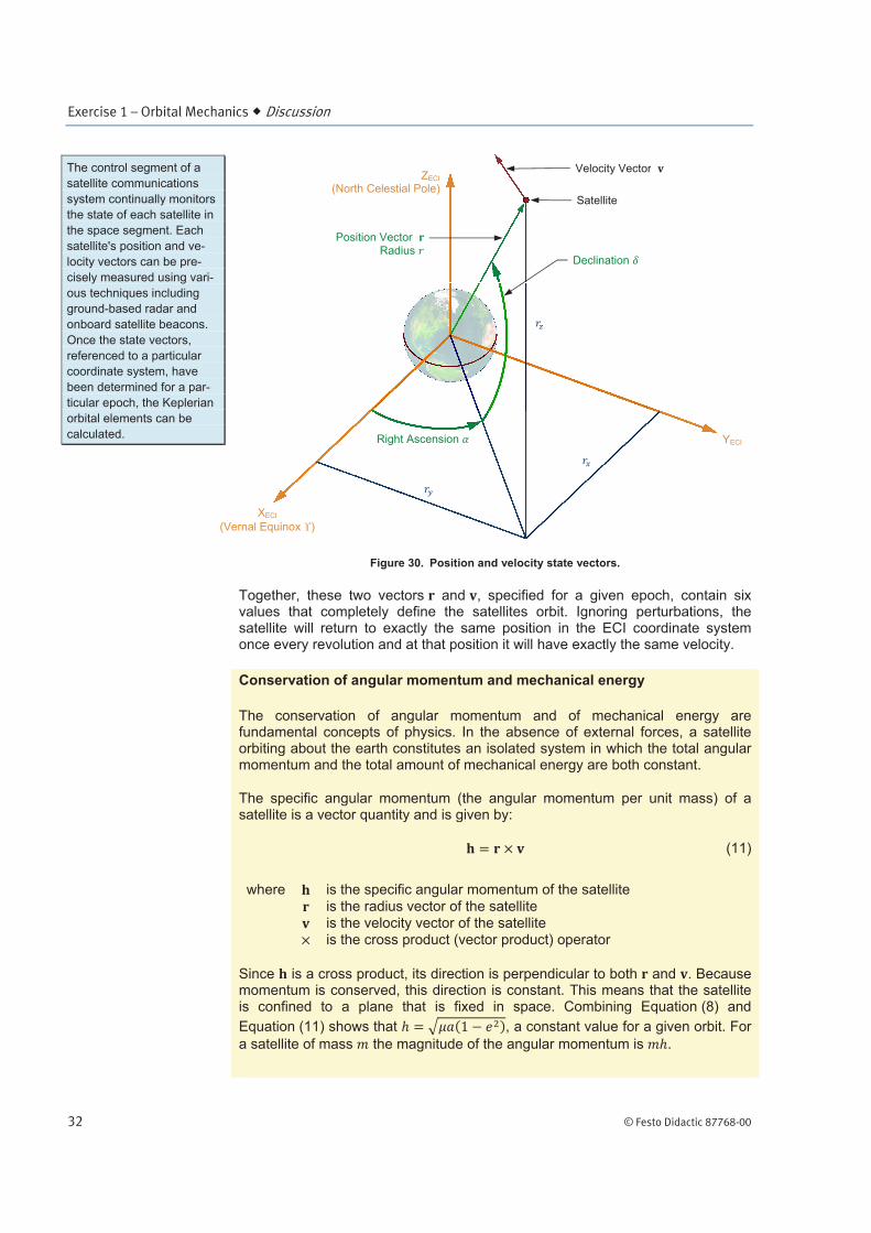
Orbital state vectors
r v
epoch
time t .
r v
Exercise 1 – Orbital Mechanics Discussion
32 © Festo Didactic 87768-00
r v
r
v

Exercise 1 – Orbital Mechanics Discussion
© Festo Didactic 87768-00 33
specific mechanical energy

Exercise 1 – Orbital Mechanics Discussion
34 © Festo Didactic 87768-00
Keplerian orbital elements
anomaly

Exercise 1 – Orbital Mechanics Discussion
© Festo Didactic 87768-00 35
a e
i
r
v

Exercise 1 – Orbital Mechanics Discussion
36 © Festo Didactic 87768-00
a Strictly speaking, inclination is never negative, since it is measured at the ascending node. In some cases, however, the concept of negative inclination is useful. For example, the inclination of geostationary satellites tends to drift slowly towards more positive values. To maintain the inclination near zero, thrusters are fired periodically to reduce the inclination to a slightly negative value, after which it begins to drift positive again.
In the LVSAT Orbit Simulator, inclination can be set between ±180°.
apsides
perigeeapogee perihelion aphelion
perigee periapsis
argument of periapsis
longitude of the ascend-
ing node

Exercise 1 – Orbital Mechanics Discussion
© Festo Didactic 87768-00 37
Anomalies
a a E
ae
a
E

Exercise 1 – Orbital Mechanics Discussion
38 © Festo Didactic 87768-00
area
time
:

Exercise 1 – Orbital Mechanics Discussion
© Festo Didactic 87768-00 39

Exercise 1 – Orbital Mechanics Discussion
40 © Festo Didactic 87768-00

Exercise 1 – Orbital Mechanics Discussion
© Festo Didactic 87768-00 41
r
r
Orbit classifications
By period
a multiple
equal

Exercise 1 – Orbital Mechanics Discussion
42 © Festo Didactic 87768-00
By altitude

Exercise 1 – Orbital Mechanics Discussion
© Festo Didactic 87768-00 43
h
By inclination
direct prograde orbit
retrograde orbit
By eccentricity

Exercise 1 – Orbital Mechanics Discussion
44 © Festo Didactic 87768-00
Subsatellite point and ground track

Exercise 1 – Orbital Mechanics Procedure Outline
© Festo Didactic 87768-00 45
a The first section of the following Procedure is designed to familiarize you with the LVSAT Orbit Simulator. In order to save time, it is suggested that you read the information presented in yellow boxes in this familiarization section before beginning your first laboratory period with the Orbit Simulator.
General Settings. Settings tables. Time in the Orbit Simulator. Satellite Editor.
Orbital and apparent paths.
a The procedure of this exercise is divided into sections which are independent. As the procedure is fairly long, you may wish to do it in two lab periods.
Familiarization with the LVSAT Orbit Simulator
This section will allow you to become familiar with various aspects of the Orbit Simulator. Sidebars in this section present information on windows, views, the active satellite, settings tables, controlling time, and using the Satellite Editor.
Windows
views
PROCEDURE OUTLINE
PROCEDURE

Exercise 1 – Orbital Mechanics Procedure
46 © Festo Didactic 87768-00
b

Exercise 1 – Orbital Mechanics Procedure
© Festo Didactic 87768-00 47
Views
a The Orbit view shows the relative size of the earth as a blue circle. Increasing
the semi-major axis of the orbit may only reduce the size of the blue circle, and
vice-versa.
b To pan in this view, click and drag with the mouse. To zoom in or out, roll the
mouse wheel or press the Page Up or Page Down keys.
b To view the earth from a different angle, click in the view and drag with the
mouse. This changes the camera’s angular position in the current Camera
Frame (ECI and EFG Camera Frames only). To view the earth closer up or
further away, roll the mouse wheel or press the Page Up or Page Down keys.
This changes the altitude of the camera. For fine adjustments, press and hold
the Ctrl key first.
a A light source is used in the view to produce a three-dimensional effect.
This light source has no relation to the sun; the sun is not modeled in the Orbit
Simulator.

Exercise 1 – Orbital Mechanics Procedure
48 © Festo Didactic 87768-00
Active satellite
b You can click on a satellite in the 3D view to make it the active satellite.
Active Satellite
General Settings

Exercise 1 – Orbital Mechanics Procedure
© Festo Didactic 87768-00 49
Time in the Orbit Simulator
Controlling time
t
a Real solar time is measured by the apparent movement of the sun. The length
of a solar day is 24:00:00. Since the sun is not represented in the Orbit
Simulator, the displayed Solar Time only represents the number of solar hours
elapsed since time was started or reset.
t0 M
Mean Anomaly at Epoch M0
sidereal time

Exercise 1 – Orbital Mechanics Procedure
50 © Festo Didactic 87768-00
Run
Pause
Reset
a Changing the Speed of time, or pausing time, makes the animation run faster
or slower, or stops it altogether. However, this does not change the Position
Rates displayed in the Information window. For example, a geostationary
satellite has a speed of approximately 3.07 km/s regardless of the current
Speed of time in the animation.
b When time is paused, you can click in the Time window and roll the mouse
wheel to advance or recede time by small increments that depend on the
magnitude of the current Speed setting. For fine control of time when using
the mouse wheel, set the Speed to a low value.
bb
Exercise 1 – Orbital Mechanics Procedure
© Festo Didactic 87768-00 51

Exercise 1 – Orbital Mechanics Procedure
52 © Festo Didactic 87768-00
Satellite Editor
Using the Satellite Editor
SatellitesEdit
Add
Remove

Exercise 1 – Orbital Mechanics Procedure
© Festo Didactic 87768-00 53
Reference frames and coordinate systems
In this section, you will show the different axes available in the Orbit Simulator. You will use the Camera Frame setting to change the reference frame used to generate the image presented to the user.
a Initial conditions: All satellites have been removed.

Exercise 1 – Orbital Mechanics Procedure
54 © Festo Didactic 87768-00
Camera Frame
Camera Frame
Camera Frame
Camera Frame
Camera Frame

Exercise 1 – Orbital Mechanics Procedure
© Festo Didactic 87768-00 55
b

Exercise 1 – Orbital Mechanics Procedure
56 © Festo Didactic 87768-00
a In the Satellite Camera Frame, you cannot change the angular position of the camera. You can, however, move the camera above or below the satellite.
Types of orbits
In this section, you will load a file containing satellites with different types of orbits. You will observe how the orbital elements determine the type of orbit and its characteristics.

Exercise 1 – Orbital Mechanics Procedure
© Festo Didactic 87768-00 57
File Load SatellitesYes
a The pre-configured satellite files are typically installed in the folder: C:\Program Files\Lab-Volt\LVSat\Orbit Simulator\Satellite Files.
It is suggested that you store user-created satellite files in a different folder.
a By default, a “P” identifies the perigee of each orbit. However, when the eccentricity , the orbit is circular and there is no perigee. In this case, the “P” shows where the perigee would be, according to the current Argument of Perigee setting, if the eccentricity were to become non-zero.

Exercise 1 – Orbital Mechanics Procedure
58 © Festo Didactic 87768-00

Exercise 1 – Orbital Mechanics Procedure
© Festo Didactic 87768-00 59
File Save Satellites As
b

Exercise 1 – Orbital Mechanics Procedure
60 © Festo Didactic 87768-00
Apparent paths
In this section, you will observe how the paths of various satellites actually appear to an observer using two different camera frames.
b

Exercise 1 – Orbital Mechanics Procedure
© Festo Didactic 87768-00 61
b

Exercise 1 – Orbital Mechanics Procedure
62 © Festo Didactic 87768-00
b

Exercise 1 – Orbital Mechanics Procedure
© Festo Didactic 87768-00 63
b
Orbit shape and size
In this section, you will observe how the orbital elements of a satellite determine the shape and size of its orbit.

Exercise 1 – Orbital Mechanics Procedure
64 © Festo Didactic 87768-00
b
b

Exercise 1 – Orbital Mechanics Procedure
© Festo Didactic 87768-00 65
b

Exercise 1 – Orbital Mechanics Procedure
66 © Festo Didactic 87768-00
State vectors and their components
In this section, you will observe the state vectors of a satellite. You will note the values of the components of these vectors, expressed in spherical coordinates, as displayed in the Information window. For different types of orbits, you will note which components are fixed and which are constantly changing.
0.0
1.0
2.0
3.0
4.0
5.0
6.0
0
200
400
600
800
1000
1200
1400
1600
10,000 15,000 20,000 25,000 30,000 35,000 40,000 45,000

Exercise 1 – Orbital Mechanics Procedure
© Festo Didactic 87768-00 67
b

Exercise 1 – Orbital Mechanics Procedure
68 © Festo Didactic 87768-00

Exercise 1 – Orbital Mechanics Procedure
© Festo Didactic 87768-00 69
a As only the principles are important, do not include units in your calculations. The rounding off of values displayed in the Information window may introduce a small error in your calculations.
Orientation of the orbit and position in orbit
In this section, you will observe how the orbital elements of a satellite determine the orientation of the orbit in space and the position of the satellite in its orbit.
b

Exercise 1 – Orbital Mechanics Procedure
70 © Festo Didactic 87768-00
a For a perfectly equatorial orbit (inclination = 0 ), the RAAN is undefined. Since the orbit is in the plane of the equator, there is no ascending node. In the Orbit Simulator, however, the RAAN is always defined as the angle at which the ascending node would appear if the inclination became non-zero.
a For each orbit, a “P” in the 3D view identifies the perigee. For a perfectly circular orbit (eccentricity = 0), there is no perigee and the Argument of Perigee as well as all of the anomalies are undefined. In the Orbit Simulator, however, the “P” shows where the perigee would be located, according to the current Argument of Perigee setting, if the eccentricity became non-zero. The anomalies are defined as the angles measured from this point.

Exercise 1 – Orbital Mechanics Procedure
© Festo Didactic 87768-00 71
Subsatellite point and ground track
In this section, you will observe the subsatellite point and ground track for several different types of orbits. (As the procedure of this exercise is rather long, this final section is optional.)
b
b

Exercise 1 – Orbital Mechanics Procedure
72 © Festo Didactic 87768-00
b
b
Tools Options

Exercise 1 – Orbital Mechanics Procedure
© Festo Didactic 87768-00 73
b

Exercise 1 – Orbital Mechanics Conclusion
74 © Festo Didactic 87768-00
tp
CONCLUSION
REVIEW QUESTIONS

Exercise 1 – Orbital Mechanics Review Questions
© Festo Didactic 87768-00 75
equatorial orbit polar orbit prograde orbit retrograde orbit