excel 10 lon s - honeywell.be · xl10 system specification guide honeywell xl10guide.doc july 1999...
TRANSCRIPT

Honeywell
EXCEL 10 LON SYSTEM
Specification Guide
XL10 System Specification Guide Honeywell
XL10GUIDE.DOC July 1999 page 2
CONTENTS
1. General Characteristics 3
2. System Architecture 3
3. Communication Structure 4
4. Modularity of the Excel 10 System 4
4.1. Stand-alone System 5
4.2. LON Network System 7
4.3. Small System 8
4.4. EXCEL 5000 Building Management System 10
5. Excel 10 components functionalities 11
5.1. Fan Coil controller W7752 12
5.1.1. Specification 13
5.2. Variable Air Volume controller W7751 16
5.2.1. Specification 17
5.3. Hydronic controller W7762 20
5.3.1. Specification 21
5.4. Chilled Ceiling controller W7763 23
5.4.1. Specification 24
5.5. Constant Volume Air Handling Unit controller W7750 26
5.5.1. Specification 27
5.6. Unit Ventilator controller W7753 30
5.6.1. Specification 31
5.7. Remote Input/Output Module W7761 34
5.8. Zone Manager Q7750 35
5.9. Room Units T7560 and T7460 36

XL10 System Specification Guide Honeywell
XL10GUIDE.DOC July 1999 page 3
1. General Characteristics
The Excel 10 system architecture for terminal units control, in HVAC systems, is adirect digital control system which provides all the functionalities concerning theroom or zone control, the monitoring, supervision and maintenance of the HVACplants.
The characteristics of the Excel 10 system make it suitable as a solution for thecomplete building automation concerning the integration with other non-HVACproducts, used for creating the global building control solution.
Excel 10 system components are based on local room or equipment microprocessormodules containing the application software.
The modularity and flexibility of the modules with the availability of standardembedded application software provide for the capability of realising all the types ofsystems, from the simple HVAC application, such as radiator or two pipes fan coil,through to complex systems such as variable air volume or chilled ceiling plants.
The hardware and software of the Excel 10 system, are designed to best fit theequipment to be controlled, and best match the direct digital algorithm controls andenergy saving requirements, and interfaces with other application products (lighting,access control, fire and security etc.) in the BMS system.
Excel 10 is based on the Echelon communication system; all the Excel 10 roommodules are LONMARK compliant and capable of interoperation with other Excel 10modules or third party LONMARK products.
2. System Architecture
The Excel 10 architecture is based on a distributed control concept with two gerarchiclevels:
• Room/zone level This level comprises of room or equipment control modules and field devices such as
actuators and sensors. The modules perform the control algorithm as configuredand communicate to the LON network.
• BMS levelCommunication to the Building Management System is performed through theZone Manager module which applies as an interface between the room modulesand the Central supervisor.
Therefore each Excel 10 module can operate either in stand-alone mode or interfacedto the BMS; anyway the operation of the room modules is totally independent of theBMS.

XL10 System Specification Guide Honeywell
XL10GUIDE.DOC July 1999 page 4
3. Communication Structure
To obtain the maximum flexibility in placing the Excel 10 modules in everyroom/zone and make the installation easier and cheaper, the room modules areconnected to the LON network.
The Excel 10 modules share data over the network, by using the standard LONWORKS
protocol. This makes it possible to create interactions between the several roommodules.
The communication over the LON network is performed via the FTT transceivers at abaud rate of 78 kBd.
Any type of standard unshielded cables can be used to wire the network.
4. Modularity of the Excel 10 System
The flexibility and modularity of the system make Excel 10 suitable for severaltypologies of applications, and particularly allow for realising simple configurationsthat can be updated in future without modifying the basic structure of the system oradding additional installation and engineering costs.
The Excel 10 system provides modules that allow:
• monitoring of analog and digital signals
• controlling of valve or damper actuators
• controlling of two-stage actuators and binary devices
• controlling of Pulse Width Modulating devices
• displaying and modifying of the control parameters, individually, per room via auser friendly LCD operator terminal,
The system operates the control functions and energy saving programs individually inevery room, using standard software modules.
These software modules are stored in the room/equipment devices, and are activatedat the start-up of the system, depending on the customised individual configuration.
The characteristic of using a standard embedded software guaranties the applicationof a tested software, and saves time and costs for engineering customised software.
The modules also provide a set of preconfigured parameters like setpoints, PID gainsetc.. They are based on the most common used values.
The software modules also provide for a diagnostic procedure in order tocommunicate any failure conditions.
XL10 System Specification Guide Honeywell
XL10GUIDE.DOC July 1999 page 5
Particularly, because of its flexibility, Excel 10 is suitable for realising the system inthe following different steps:
• Stand-alone system
• LON network system
• Small system
• Building management system
Depending on the type of system installation, the Excel 10 room modules providedifferent types of functionalities.
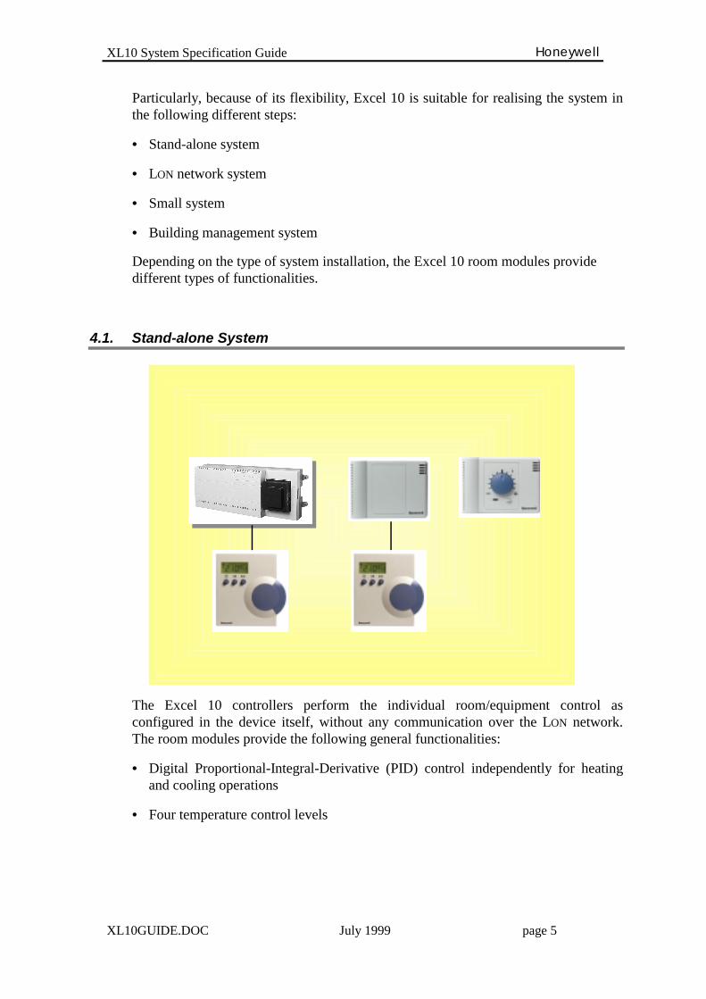
4.1. Stand-alone System
The Excel 10 controllers perform the individual room/equipment control asconfigured in the device itself, without any communication over the LON network.The room modules provide the following general functionalities:
• Digital Proportional-Integral-Derivative (PID) control independently for heatingand cooling operations
• Four temperature control levels
XL10 System Specification Guide Honeywell
XL10GUIDE.DOC July 1999 page 6
∗ Occupancy mode level the temperature comfort level value is controlled by the room modules
∗ Standby mode level the temperature level is controlled when the configured Presence Sensor
detects no-presence in the room. The temperature control level is changed inthe energy saving direction (heating setpoint decreased and cooling setpointincreased) as configured
∗ Unoccupied mode level the temperature level is controlled, when the override command is issued by
the wall module push-button. The temperature control level is changed to anunoccupancy value as configured
∗ Frost Protection mode level the temperature level is controlled when the configured Window Switch
detects an open window in the room. The heating valves are closed, unlessthe room temperature drops down the minimum limit
• Zero Energy Band between heating and cooling operations
• Operating mode override
∗ Bypass mode by pressing the wall module push-button, the room module is commanded to
work in Occupancy mode for a configured period of time
∗ Unoccupancy mode by pressing the wall module push-button, the operating mode is commanded
to Unoccupancy as long as a next override is coming
• Presence monitoring by an external switch or a presence device
∗ Presence detection it operates the occupancy mode and the comfort temperature level
∗ No-Presence detection it operates the standby mode and the standby temperature level
• Window monitoring by a window switch
∗ Window open it operates the frost protection mode
∗ Window closed it operates the occupancy mode and the comfort temperature level
• Changeover control for the two pipe equipment

XL10 System Specification Guide Honeywell
XL10GUIDE.DOC July 1999 page 7
4.2. LON Network System
The Excel 10 controllers perform the individual room/equipment control asconfigured in the device itself. Additionally, they communicate over the LON networkwith the other Excel 10 room modules and/or third party LONMARK products.
Over the LON network, it is possible to create interoperations between the differentmodules, in order to improve the automation and the flexibility of the system.
• Occupancy command An occupancy command can be shared over the network between the Excel
10 room modules. It can be either a presence switch connected to a masterroom module or a network signal coming from a presence device
• Window override A window position signal can be shared over the network between the Excel
10 room modules. It can be either a window switch connected to a masterroom module or a network signal coming from a LONMARK switch
• Master/Slave operation The Excel 10 modules can share all the room control data such as room
temperature, actual operating setpoint etc., over the network. They can beused with other room modules in order to create relationships between theseveral controllers and operate a master/slave interactions.
XL10 System Specification Guide Honeywell
XL10GUIDE.DOC July 1999 page 8
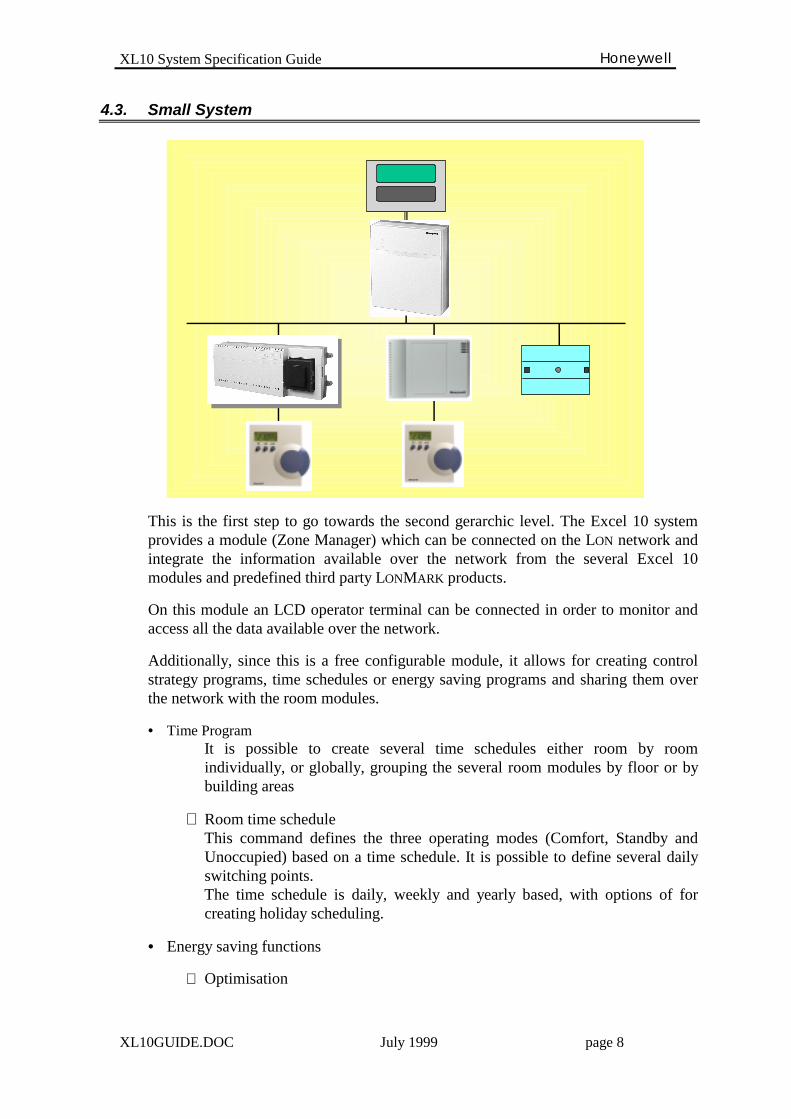
4.3. Small System
This is the first step to go towards the second gerarchic level. The Excel 10 systemprovides a module (Zone Manager) which can be connected on the LON network andintegrate the information available over the network from the several Excel 10modules and predefined third party LONMARK products.
On this module an LCD operator terminal can be connected in order to monitor andaccess all the data available over the network.
Additionally, since this is a free configurable module, it allows for creating controlstrategy programs, time schedules or energy saving programs and sharing them overthe network with the room modules.
• Time Program It is possible to create several time schedules either room by room
individually, or globally, grouping the several room modules by floor or bybuilding areas
∗ Room time schedule This command defines the three operating modes (Comfort, Standby and
Unoccupied) based on a time schedule. It is possible to define several dailyswitching points.
The time schedule is daily, weekly and yearly based, with options of forcreating holiday scheduling.
• Energy saving functions
∗ Optimisation

XL10 System Specification Guide Honeywell
XL10GUIDE.DOC July 1999 page 9
The Excel 10 room modules perform the optimum start function in order toguarantee the temperature comfort level for the desired occupancy time.
The optimum start is performed individually by room, depending on theroom temperature conditions and it is achieved via a configurable recoveryramp. This is particularly important because it allows the primary equipment,such as chillers or boilers not to be charged from the maximum cooling orheating demand at the same time.
∗ Room temperature compensation An outdoor temperature sensor can be connected either to a room module or
directly to the LON network (LONMARK sensor) in order to share with all theroom modules an offset value for the Summer/Winter temperature levelreset: the offset value can be individually defined for each room.
• Summer/Winter changeover control for the two pipe equipment (e.g. fan coil).
• Special control strategies can be built in order to improve the automation and thespecific functionalities of the room modules.
• The full access to the room modules gives the possibility to monitor and changeall the data and parameters of the room modules.
XL10 System Specification Guide Honeywell
XL10GUIDE.DOC July 1999 page 10
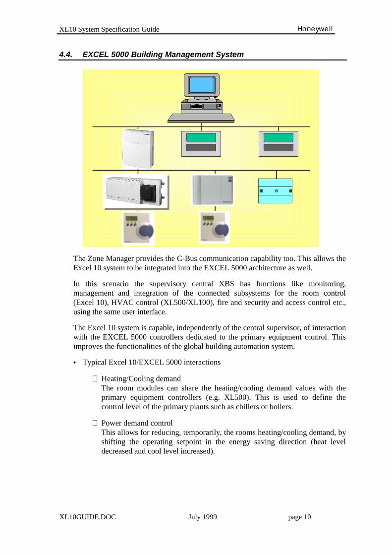
4.4. EXCEL 5000 Building Management System
The Zone Manager provides the C-Bus communication capability too. This allows theExcel 10 system to be integrated into the EXCEL 5000 architecture as well.
In this scenario the supervisory central XBS has functions like monitoring,management and integration of the connected subsystems for the room control(Excel 10), HVAC control (XL500/XL100), fire and security and access control etc.,using the same user interface.
The Excel 10 system is capable, independently of the central supervisor, of interactionwith the EXCEL 5000 controllers dedicated to the primary equipment control. Thisimproves the functionalities of the global building automation system.
• Typical Excel 10/EXCEL 5000 interactions
∗ Heating/Cooling demand The room modules can share the heating/cooling demand values with the
primary equipment controllers (e.g. XL500). This is used to define thecontrol level of the primary plants such as chillers or boilers.
∗ Power demand control This allows for reducing, temporarily, the rooms heating/cooling demand, by
shifting the operating setpoint in the energy saving direction (heat leveldecreased and cool level increased).
XL10 System Specification Guide Honeywell
XL10GUIDE.DOC July 1999 page 11
∗ Third party products handling All the third party products data available via the Zone Manager, can be used
to improve the automation functionalities of the system. All of those data areshown on the central supervisor in the same way as the EXCEL 5000 data.
5. Excel 10 components functionalities
The Excel 10 system provides a range of room and equipment modules that can beused and configured to best match the required application.
Specifically there are the following modules:
• Fan Coil unit W7752
• Variable Air Volume unit W7751
• Hydronic unit W7762
• Chilled Ceiling unit W7763
• Constant Volume Air Handling unit W7750
• Unit Ventilator Controller W7753
• Remote Input/Output Module W7761
• Zone Manager module Q7750
• LON Digital Display Wall Module T7780
• Room Units T7560 and T7460
XL10 System Specification Guide Honeywell
XL10GUIDE.DOC July 1999 page 12
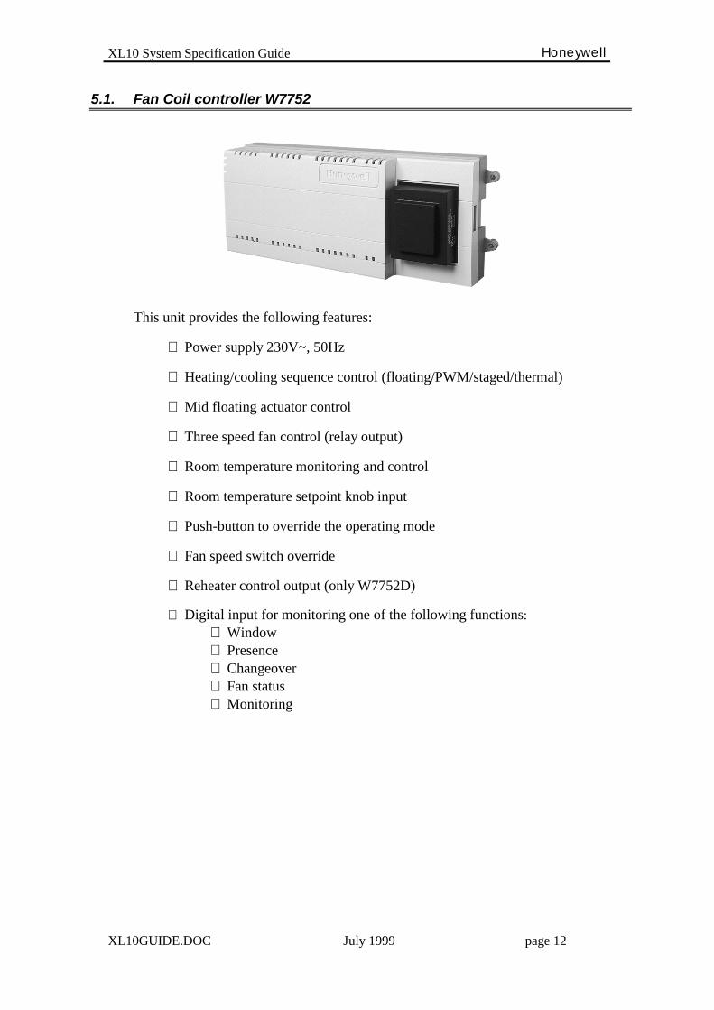
5.1. Fan Coil controller W7752
This unit provides the following features:
∗ Power supply 230V~, 50Hz
∗ Heating/cooling sequence control (floating/PWM/staged/thermal)
∗ Mid floating actuator control
∗ Three speed fan control (relay output)
∗ Room temperature monitoring and control
∗ Room temperature setpoint knob input
∗ Push-button to override the operating mode
∗ Fan speed switch override
∗ Reheater control output (only W7752D)
∗ Digital input for monitoring one of the following functions:⇒ Window⇒ Presence⇒ Changeover⇒ Fan status⇒ Monitoring
XL10 System Specification Guide Honeywell
XL10GUIDE.DOC July 1999 page 13
5.1.1. Specification
♦ Power supplyThe fan coil controller is supplied with 230 Vac, 50 Hz. The fan relays aresupplied by the same power supply line to reduce the wiring and installation effort.
♦ Heating and Cooling sequence controlThe controller provides the heating and cooling sequence control based on theroom or exhaust temperature sensor. The controller has settable PID parameters forboth heating and cooling.The controller provides a settable “zero energy band” across the operating setpoint,within which the heating and cooling actuators are driven to the closed position.
∗ Floating actuator control The unit controls the 3-point actuator by two triac outputs for opening and
closing the actuator. For both heating and cooling actuators the running timesare settable. Every 24 hours the actuators are synchronised to the closedposition.
∗ Pulse Width Modulating control (PWM) The heating/cooling sequence control value is converted in a duty cycle
signal that supplies the triac outputs with 24 Vac. This signal can beconverted into an analog voltage/current signal by an external device, toconnect modulating actuators.
∗ Staged control The unit controls on/off equipment (such as electric coils) with up to three
stages for both heating and cooling. The controller provides settableswitching levels for the stages based on the heating and cooling controlsequence.
∗ Mid-floating control The controller provides the heating/cooling sequence control to modulate the
position of a damper actuator which mixes the cold and hot air to be suppliedin the room. When the set room temperature is achieved, the actuator isdriven to the mid position.
♦ Fan controlThe controller provides up to three speeds control. The switching levels for the fanspeeds are freely settable and are based on the heating/cooling demand.During the occupancy mode and within the “zero energy band”, the fan can beswitched off to save energy or can be controlled at the lowest speed.The controller provides settable run-up and overrun times to guarantee theventilation during the reheater command.
XL10 System Specification Guide Honeywell
XL10GUIDE.DOC July 1999 page 14
♦ Fan interlockThe fan control can be set to be related to the heating and cooling actuatorsposition, in order to avoid the fan running with the actuators not operating.
♦ Reheater controlThe controller provides the electric reheater control. The switching level can be setbased on the heating demand.
♦ Free output controlThe fourth relay output can be freely controlled via the network. The command cancome from the Zone Manager where it can be based on control strategy or timeprogram. In this way it is possible to control some electric accessories of the roomsuch as lighting, sunblind etc.
♦ Room frost protectionThe controller detects the window position by a digital input or a network signal.When the opened window is detected the controller closes the heating/damperactuators, switches off the fan and sets the room temperature setpoint at 8°C. If thetemperature then falls below 8°C it opens the heating actuator, controls thedamper for the minimum air flow and switches on the fan to avoid any frostcondition. The normal operation is established as soon as the closed window isdetected.
♦ Presence detectionThe controller detects the occupancy of the room by a digital input or a networksignal. When the non-presence is detected the controller changes the operatingmode to Standby to save energy. In this condition the “zero energy band” isincreased and the operating heating/cooling setpoints are shifted in the energysaving direction (decrease heating setpoint and increase cooling setpoint).
♦ Changeover controlThe controller controls a two pipes fan coil unit. The selection of heating orcooling operating mode can be controlled by a digital input or a network signal.
♦ Occupancy overrideIt is possible to override the occupancy mode of the controller by pressing thepush-button on the wall module. It is possible to bypass the occupancy period for asettable time in order to extend, temporarily, the occupancy of the room. It is alsopossible to place the controller in unoccupied mode until another command eitherfrom the network or from the wall module resets the normal operation of the unit.It is possible to override the fan speed by the manual switch on the wall module. Ifthe switch is placed to “0” the controller closes the heating/cooling actuators andswitches off the fan until the switch is either placed to “Auto” or to a manual speedcontrol (1 or 2 or 3).
XL10 System Specification Guide Honeywell
XL10GUIDE.DOC July 1999 page 15
♦ Heating/Cooling demandThe controller calculates the room heating/cooling demand based on the actuatorsposition, and sends this value over the network. This value can be read in the ZoneManager that calculates the maximum, minimum or average value to be used forcontrolling the operation of the primary equipment (e.g. chiller setpoint reset).
♦ Optimum StartBased on the time schedule and a recovery ramp, the controller gradually ramps thesetpoints between the occupancy modes in order to optimise the temperaturecontrol during the preheating or precooling phase (e.g. during the morning start-up) and ensure the preset occupancy temperature conditions. This also prevents theprimary heating and cooling equipment (e.g. boilers, chillers) from beingoverloaded by the maximum heating and cooling demand from the roomcontrollers.The recovery ramps for heating and cooling operations are independently settable.
♦ Power demand limitA power demand signal can be sent over the network to the controller; In that case,the controller shifts the operating setpoints (heat/cool) by a settable offset in theenergy saving direction (decrease heating setpoint and increasing cooling setpoint)in order to increase the “zero energy band”. The normal operation is established assoon as the power demand signal is no longer present.
XL10 System Specification Guide Honeywell
XL10GUIDE.DOC July 1999 page 16
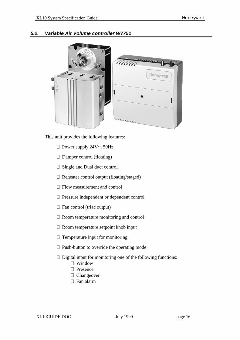
5.2. Variable Air Volume controller W7751
This unit provides the following features:
∗ Power supply 24V~, 50Hz
∗ Damper control (floating)
∗ Single and Dual duct control
∗ Reheater control output (floating/staged)
∗ Flow measurement and control
∗ Pressure independent or dependent control
∗ Fan control (triac output)
∗ Room temperature monitoring and control
∗ Room temperature setpoint knob input
∗ Temperature input for monitoring
∗ Push-button to override the operating mode
∗ Digital input for monitoring one of the following functions:⇒ Window⇒ Presence⇒ Changeover⇒ Fan alarm

XL10 System Specification Guide Honeywell
XL10GUIDE.DOC July 1999 page 17
5.2.1. Specification
♦ Heating and Cooling sequence controlThe controller provides the heating and cooling sequence control based on theroom temperature sensor and the box air flow. The controller has settable PIDparameters for both heating and cooling.The controller provides a settable “zero energy band” across the operating setpoint,within which the heating actuator is driven to the closed position and the damper iscontrolled to ensure the minimum air flow in the room.
∗ Floating actuator control The unit controls the 3-point actuator by two triac outputs for opening and
closing the actuator. For both heating and damper actuators the running timesare settable. Every 24 hours the actuators are synchronised to the closedposition.
∗ Reheater staged control The unit controls on/off equipment (such as electric reheater) with up to
three stages (SVAV up to two stages). The controller provides settableswitching levels for the stages based on the heating and cooling controlsequence.
♦ Pressure Independent controlThe controller uses the air flow as primary means of control. It controls a fixed airflow setpoint that is reset based on space temperature conditions or other local ornetwork requirements.
♦ Pressure Dependent controlThe controller uses the room temperature as a primary means of control. With thissetting, the controller ignores the controller air flow input and maintains the roomconditions by modulating the damper and the reheater outputs based on the roomtemperature.
♦ Single Duct controlThe controller controls a VAV box with a single supply inlet connection. The boxcan be a cooling box or a central cooling with local reheat or centralheating/cooling. The box can be with or without an air flow sensor.
♦ Dual Duct controlThe controller controls a VAV box with separate supply inlets for cooling andheating. The box can have a single flow sensing device in the discharge air in oneof the two supply inlets, or it can be configured with a sensing device for eachsupply inlet. The box can also be without an air flow sensor.
XL10 System Specification Guide Honeywell
XL10GUIDE.DOC July 1999 page 18
♦ Flow Tracking controlThe controller controls a VAV box that tracks the supply air flow into the room.The controller is slaved to the supply controller and tracks the supply air. The boxhas to require an air flow sensor.
♦ Direct coupled damper actuatorThe SVAV controller provides the damper actuator onboard..This is coupled onthe VAV box to control the air flow.
♦ Minimum Air FlowThe minimum air flow is settable in the controller. The minimum air flow iscontrolled during the occupancy mode. During the standby and unoccupancymodes, the controller closes the damper and switches off the fan.
♦ Room frost protectionThe controller detects the window position by a digital input or a network signal.When the opened window is detected. The controller closes the heating/damperactuators, switches off the fan and sets the room temperature setpoint at 8°C. If thetemperature then falls below 8°C it opens the heating actuator, controls thedamper for the minimum air flow and switches on the fan to avoid any frostcondition. The normal operation is established as soon as the closed window isdetected.
♦ Presence detectionThe controller detects the occupancy of the room by a digital input or a networksignal. When the non-presence is detected the controller changes the operatingmode to Standby to save energy. In this condition the “zero energy band” isincreased and the operating heating/cooling setpoints are shifted in the energysaving direction (decrease heating setpoint and increase cooling setpoint).
♦ Changeover controlThe controller controls the air flow damper for both heating and cooling. Theselection of the operating mode can be controlled either by a digital input or via anetwork command.
♦ Occupancy overrideIt’s possible to override the occupancy mode of the controller by pressing the push-button on the wall module. It is possible to bypass the occupancy period for asettable time in order to extend, temporarily, the occupancy of the room. It is alsopossible to place the controller in unoccupied mode until another command eitherfrom the network or from the wall module resets the normal operation of the unit.
♦ Heating/Cooling demandThe controller calculates the room heating/cooling demand based on the actuatorsposition, and shares this value over the network. This value can be read in the ZoneManager that calculates the maximum, minimum or average value to be used forcontrolling the operation of the primary equipment (e.g. chiller setpoint reset).
XL10 System Specification Guide Honeywell
XL10GUIDE.DOC July 1999 page 19
♦ Optimum StartBased on the time schedule and a recovery ramp, the controller gradually increasesthe setpoints between the occupancy mode in order to optimise the temperaturecontrol during the preheating or precooling phase (e.g. during the morning start-up) and ensure the preset occupancy temperature conditions. This also preventsthe primary heating and cooling equipment (e.g. boilers, chillers) from beingoverloaded by the maximum heating and cooling demand from the roomcontrollers.The recovery ramps for heating and cooling operations are independently settable.
♦ Power demand limitA power demand signal can be sent over the network to the controller. In that case,the controller shifts the operating setpoints (heat/cool) by a settable offset in theenergy saving direction (decrease heating setpoint and increasing cooling setpoint)in order to increase the “zero energy band”. The normal operation is established assoon as the power demand signal is no longer present.

XL10 System Specification Guide Honeywell
XL10GUIDE.DOC July 1999 page 20
5.3. Hydronic controller W7762
This unit provides the following features:
∗ Power supply 24V~, 50Hz
∗ Heating/cooling sequence control (floating/PWM/staged/thermal)
∗ Mid floating actuator control
∗ Room temperature monitoring and control
∗ Room temperature setpoint knob input
∗ Push-button to override the operating mode
∗ Digital input for monitoring one of the following functions:⇒ Window⇒ Presence⇒ Changeover⇒ Fan Status⇒ Monitoring

XL10 System Specification Guide Honeywell
XL10GUIDE.DOC July 1999 page 21
5.3.1. Specification
♦ Heating and Cooling sequence controlThe controller provides the heating and cooling sequence control based on theroom or exhaust temperature sensor. The controller has settable PID parameters forboth heating and cooling.The controller provides a settable “zero energy band” across the operating setpoint,in which the heating and cooling actuators are driven to the closed position.
∗ Floating actuator control The unit controls the 3-point actuator by two triac outputs for opening and
closing the actuator. For both heating and cooling actuators the running timesare settable. Every 24 hours the actuators are synchronised to the closedposition.
∗ Pulse Width Modulating control The heating/cooling sequence control value is converted in a duty cycle
signal that supplies the triac outputs with 24 Vac. This signal can beconverted into an analog voltage/current signal by an external device, toconnect modulating actuators.
∗ Staged control The unit controls on/off equipment (such as electric coils) with up to three
stages for both heating and cooling. The controller provides settableswitching levels for the stages based on the heating and cooling controlsequence.
∗ Mid-floating control The controller provides the heating/cooling sequence control to modulate the
position of a damper actuator which mixes the cold and hot air to be suppliedin the room. When the set room temperature is achieved, the actuator isdriven to the mid position.
♦ Room frost protectionThe controller detects the window position by a digital input or a network signal.When the opened window is detected the controller closes the heating/damperactuators, switches off the fan and set the room temperature setpoint at 8°C. If thetemperature then falls below 8°C it opens the heating actuator, controls thedamper for the minimum air flow and switches on the fan to avoid any frostcondition. The normal operation is established as soon as the closed window isdetected.
♦ Presence detectionThe controller detects the occupancy of the room by a digital input or a networksignal. When the non-presence is detected the controller changes the operatingmode to Standby to save energy. In this condition the “zero energy band” isincreased and the operating heating/cooling setpoints are shifted in the energysaving direction (decrease heating setpoint and increase cooling setpoint).
XL10 System Specification Guide Honeywell
XL10GUIDE.DOC July 1999 page 22
♦ Changeover controlThe controller controls a two pipe unit. Selection of heating or cooling operatingmode can be controlled either by a digital input or via a network command.
♦ Occupancy overrideIt is possible to override the occupancy mode of the controller by pressing thepush-button on the wall module. It is possible to bypass the occupancy period for asettable time in order to extend temporarily the occupancy of the room. It is alsopossible to place the controller in unoccupied mode until another command eitherfrom the network or from the wall module resets the normal operation of the unit.
♦ Heating/Cooling demandThe controller calculates the room heating/cooling demand based on the actuatorsposition, and sends this value over the network. This value can be read in the ZoneManager that calculates the maximum, minimum or average value to be used forcontrolling the operation of the primary equipment (e.g. chiller setpoint reset).
♦ Optimum StartBased on the time schedule and a recovery ramp, the controller gradually ramps thesetpoints between the occupancy modes in order to optimise the temperaturecontrol during the preheating or precooling phase (e.g. during the morning start-up) and ensure the preset occupancy temperature conditions. This also prevents theprimary heating and cooling equipment (e.g. boilers, chillers) from beingoverloaded by the maximum heating and cooling demand from the roomcontrollers.The recovery ramps for heating and cooling operations are independently settable.
♦ Power demand limitA power demand signal can be sent over the network to the controller. In that case,the controller shifts the operating setpoints (heat/cool) by a settable offset in theenergy saving direction (decrease heating setpoint and increasing cooling setpoint)in order to increase the “zero energy band”. The normal operation is established assoon as the power demand signal is no longer present.
XL10 System Specification Guide Honeywell
XL10GUIDE.DOC July 1999 page 23
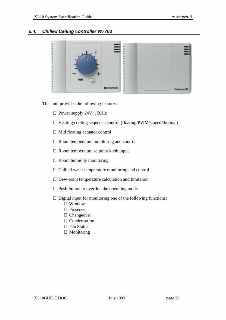
5.4. Chilled Ceiling controller W7763
This unit provides the following features:
∗ Power supply 24V~, 50Hz
∗ Heating/cooling sequence control (floating/PWM/staged/thermal)
∗ Mid floating actuator control
∗ Room temperature monitoring and control
∗ Room temperature setpoint knob input
∗ Room humidity monitoring
∗ Chilled water temperature monitoring and control
∗ Dew-point temperature calculation and limitation
∗ Push-button to override the operating mode
∗ Digital input for monitoring one of the following functions:⇒ Window⇒ Presence⇒ Changeover⇒ Condensation⇒ Fan Status⇒ Monitoring
XL10 System Specification Guide Honeywell
XL10GUIDE.DOC July 1999 page 24
5.4.1. Specification
♦ Heating and Cooling sequence controlThe controller provides the heating and cooling sequence control based on the room orexhaust temperature sensor. The controller has settable PID parameters for both heatingand cooling.The controller provides a settable “zero energy band” across the operating setpoint,within which the heating and cooling actuators are driven to the closed position.
∗ Floating actuator control The unit controls the 3-point actuator by two triac outputs for opening and
closing the actuator. For both heating and cooling actuators the running timesare settable. Every 24 hours the actuators are synchronised to the closedposition.
∗ Pulse Width Modulating control The heating/cooling sequence control value is converted in a duty cycle
signal that supplies the triac outputs with 24 Vac. This signal can beconverted in an analog voltage/current signal by an external device toconnect modulating actuators.
∗ Staged control The unit controls on/off equipment (such as electric coils) with up to three
stages for both heating and cooling. The controller provides settableswitching levels for the stages based on the heating and cooling controlsequence.
∗ Mid-floating control The controller provides the heating/cooling sequence control to modulate the
position of a damper actuator which mixes the cold and hot air to be suppliedin the room. When the set room temperature is achieved, the actuator isdriven to the mid position.
♦ Condensation protectionThe controller provides the dew-point temperature calculation based on the roomtemperature and humidity. In this case, this setpoint applies to the cold watertemperature measurement and if this temperature falls below this setpoint plus asettable security band (e.g. 2K), the controller closes the cooling actuator followinga ramp of 5 minutes.If the room humidity sensor is not connected the controller performs thecondensation protection based on a settable dew-point temperature limit thatapplies to cold water temperature measurement.If the cold water temperature is not connected the condensation protection isperformed by a digital input or a network signal.The room humidity and the cold water temperature value can also be shared via thenetwork. In this case, the sensors can be installed either on floor or zone basis.
XL10 System Specification Guide Honeywell
XL10GUIDE.DOC July 1999 page 25
♦ Room frost protectionThe controller detects the window position by a digital input or a network signal.When the opened window is detected the controller closes the heating/damperactuators, switches off the fan and sets the room temperature setpoint at 8°C. If thetemperature then falls below 8°C it opens the heating actuator, controls the damperfor the minimum air flow and switches on the fan to avoid any frost condition. Thenormal operation is established as soon as the closed window is detected
♦ Presence detectionThe controller detects the occupancy of the room by a digital input or a networksignal. When the non-presence is detected the controller changes the operating modeto Standby to save energy. In this condition the “zero energy band” is increased andthe operating heating/cooling setpoints are shifted in the energy saving direction(decrease heating setpoint and increase cooling setpoint).
♦ Changeover controlThe controller controls a two pipe unit. The selection of heating or cooling operatingmode can be controlled by a digital input or a network signal.
♦ Occupancy overrideIt is possible to override the occupancy mode of the controller by pressing the push-button on the wall module. It is possible to bypass the occupancy period for a settabletime, in order to extend temporarily the occupancy of the room. It is also possible toplace the controller in unoccupied mode until another command either from thenetwork or from the wall module resets the normal operation of the unit.
♦ Heating/Cooling demandThe controller calculates the room heating/cooling demand based on the actuatorsposition, and shares this value over the network. This value can be read in the ZoneManager that calculates the maximum, minimum or average value to be used forcontrolling the operation of the primary equipment (e.g. chiller setpoint reset).
♦ Optimum StartBased on the time schedule and a recovery ramp, the controller gradually ramps thesetpoints between the occupancy modes in order to optimise the temperature controlduring the preheating or precooling phase (e.g. during the morning start-up) andensure the preset occupancy temperature conditions. This also prevents the primaryheating and cooling equipment (e.g. boilers, chillers) from being overloaded by themaximum heating and cooling demand from the room controllers.The recovery ramps for heating and cooling operations are independently settable.
♦ Power demand limitA power demand signal can be sent over the network to the controller. In that case,the controller shifts the operating setpoints (heat/cool) by a settable offset in theenergy saving direction (decrease heating setpoint and increasing cooling setpoint) inorder to increase the “zero energy band”. The normal operation is established as soonas the power demand signal is no longer present.

XL10 System Specification Guide Honeywell
XL10GUIDE.DOC July 1999 page 26
5.5. Constant Volume Air Handling Unit controller W7750
This unit provides the following functions:
∗ Power supply 24V~, 50Hz
∗ Heating/cooling/damper sequence control (floating/PWM/staged)
∗ Up to four heating and cooling staged equipment
∗ Room temperature monitoring and control
∗ Discharge temperature limitation
∗ Room temperature setpoint knob input
∗ Free cooling algorithm
∗ Heat pump control
∗ Minimum ON/OFF time for cycling the staged equipment
∗ Push-button for override the operating mode
∗ Digital inputs for monitoring a mix of the following functions:⇒ Window⇒ Presence⇒ Time clock⇒ Changeover⇒ Monitoring⇒ Smoke sensor⇒ Shutdown⇒ Economiser⇒ Fan status⇒ Dirty filter⇒ Indoor air quality
XL10 System Specification Guide Honeywell
XL10GUIDE.DOC July 1999 page 27
5.5.1. Specification
♦ Heating and Cooling sequence controlThe controller provides the heating, cooling and damper sequence control based onthe room or exhaust temperature sensor; the cascade control is performed by thedischarge temperature sensor. The controller has settable PID parameters for bothheating and cooling.The controller provides a settable “zero energy band” across the operating setpoint,within which the heating and cooling actuators are driven to the closed position.
∗ Floating actuator control The unit controls the 3-point actuator by two triac outputs for opening and
closing the actuator. For both heating and cooling actuators the running timesare settable. Every 24 hours the actuators are synchronised to the closedposition.
∗ Pulse Width Modulating control The heating/cooling/damper sequence control value is converted in a duty
cycle signal that supplies the triac outputs with 24 Vac. This signal can beconverted in an analog voltage/current signal by an external device, toconnect modulating actuators.
∗ Staged control The unit controls on/off equipment (such as electric coils) with up to four
stages for both heating and cooling. The switching levels for the stagesdepend upon the number of the selected stages to be controlled.
∗ Cycle rates The unit provides a settable cycling rate for the staged outputs for both
heating and cooling equipment. This setting ensures the minimum operating(min ON) and pausing (min OFF) times, based on the cycle/hour rate.
♦ Discharge temperature limitA minimum discharge air temperature value (user settable) is provided bycontrolling the damper at the minimum position (user settable) and if necessary bycontrolling the heat equipment. It ensures that the discharge temperature doesn’tfall below the minimum comfort level.
♦ Outside temperature lockoutThe controller provides a maximum and a minimum outdoor air temperature value(user settable) for locking the heating and cooling equipment, above and belowcertain outside temperature conditions.
♦ Fan controlDuring the occupancy mode and within the “zero energy band”, the fan can beswitched off to save energy or can be configured to run continuously to ensure theventilation in the room.
XL10 System Specification Guide Honeywell
XL10GUIDE.DOC July 1999 page 28
♦ Free coolingThe controller supports these different strategies to allow for free cooling controlby the damper.
∗ Enable/Disable A digital input is provided to open/close the damper. The same function can
be controlled by a network signal.
∗ Outdoor Temperature If the outdoor temperature is less than a setpoint (user settable) the damper is
controlled as a cooling stage for free cooling.
∗ Differential Temperature The difference between the outdoor temperature and the return temperature
is compared to a setpoint (user settable) to define if the damper can becontrolled as a cooling stage for free cooling.
∗ Single Calculated Enthalpy the outdoor enthalpy (calculated) is compared to a setpoint (user settable), as
well the outdoor temperature is compared to a setpoint (user settable) todefine if the damper can be controlled as a cooling stage for free cooling.
∗ Differential Enthalpy sensed/calculated The difference between the outdoor enthalpy and the return enthalpy is
compared to define if the outdoor temperature is suitable for free cooling.
♦ Room frost protectionThe controller detects the window position by a digital input or a network signal.When the opened window is detected the controller closes the heating/damperactuators, switches off the fan and set the room temperature setpoint at 8°C. If thetemperature then falls below 8°C it opens the heating actuator, controls thedamper for the minimum air flow and switches on the fan to avoid any frostcondition. The normal operation is established as soon as the closed window isdetected.
♦ Occupancy overrideIt is possible to override the occupancy mode of the controller by pressing thepush-button on the wall module. It’s possible to bypass the occupancy period for asettable time, in order to extend temporarily the occupancy of the room. It is alsopossible to place the controller in unoccupied mode until another command eitherfrom the network or from the wall module resets the normal operation of the unit.
♦ Heating/Cooling demandThe controller calculates the room heating/cooling demand based on the actuatorsposition, and shares this value over the network. This value can be read in the ZoneManager that calculates the maximum, minimum or average value to be used forcontrolling the operation of the primary equipment (e.g. chiller setpoint reset).
XL10 System Specification Guide Honeywell
XL10GUIDE.DOC July 1999 page 29
♦ Optimum StartBased on the time schedule and a recovery ramp, the controller gradually increases thesetpoints between the occupancy modes, in order to optimise the temperature controlduring the preheating or precooling phase (e.g. during the morning start-up) and ensurethe preset occupancy temperature conditions; this also allows the primary heating andcooling equipment (e.g. boilers, chillers) not to be overloaded by the maximum heatingand cooling demand from the room controllers.The recovery ramps for heating and cooling operations are independently settable.
♦ Setpoint ramping for Heat PumpThe controller provides a setpoint ramping function specifically for the Heat Pumpequipment; the heating setpoint for the Heat Pump compressors is ramped up at theoccupancy level at the beginning of the calculated recovery time: the setpoint for theauxiliary heating equipment is then ramped up to the occupancy level, following thepreset ramp starting at the half of the calculated recovery time.
♦ Changeover valveThe controller provides the reversing valve control in a heat pump equipment; this valveis controlled depending on the operating mode of the unit for heating and coolingoperation.
♦ Free output controlThe controller provides up to two digital outputs which can be freely controlled from thenetwork. This command can come from the Zone Manager as a control strategy or a timebased command.
♦ Fire or smoke detectionA digital input is provided for detecting a fire or smoke alarm in the environment to becontrolled. On alarm presence, the controller supports one of these operating modes (usersettable):
∗ Emergency Shutdown: all the outputs will be shut off
∗ Depressurize: the fan will be switched on, the damper open and heat/coolequipment shut off
∗ Pressurise: the fan will be switched on, the damper closed and heat/cool equipmentshut off
♦ Indoor air quality controlThe controller controls the damper position at a preset value, depending on the air qualitysensor detection (CO2 sensor or IAQ switch). Even during this override operation, thecontroller can enable the heating equipment, if the discharge temperature drops belowthe minimum set value.
♦ Power demand limitA power demand signal can be sent over the network to the controller. In that case, thecontroller shifts the operating setpoints (heat/cool) by a settable offset in the energysaving direction (decrease heating setpoint and increasing cooling setpoint) in order toincrease the “zero energy band”. The normal operation is established as soon as thepower demand signal is no longer present.
XL10 System Specification Guide Honeywell
XL10GUIDE.DOC July 1999 page 30
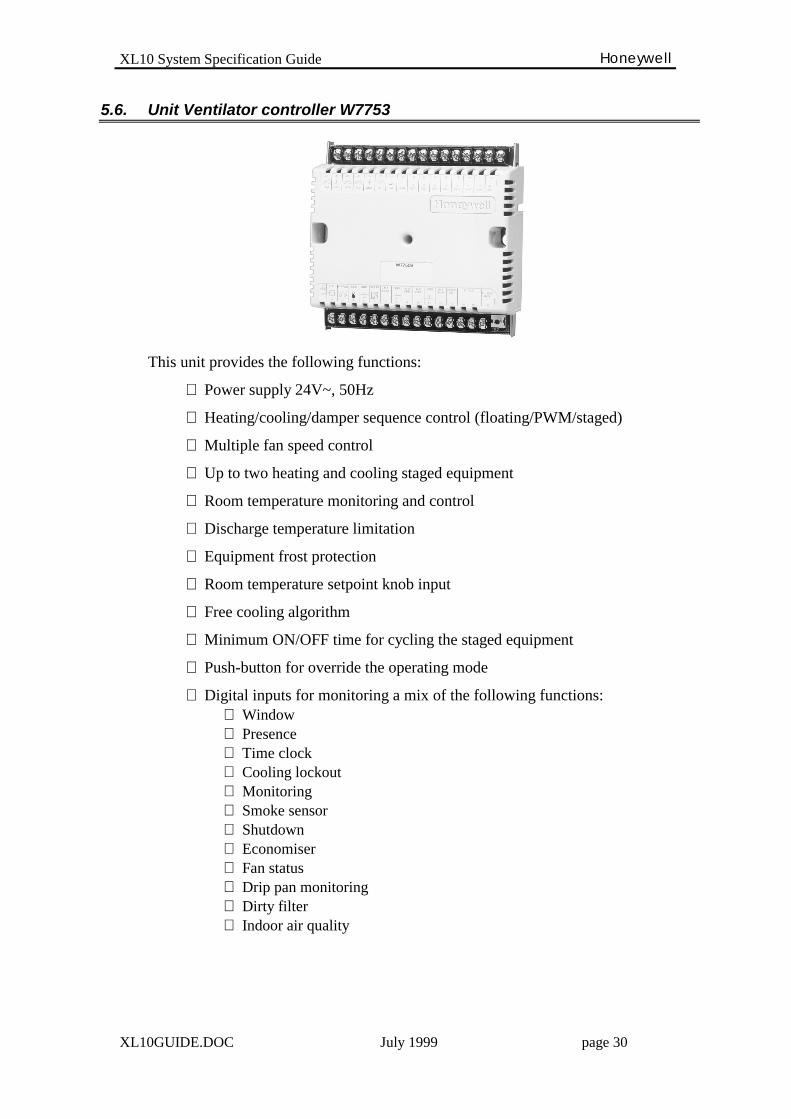
5.6. Unit Ventilator controller W7753
This unit provides the following functions:
∗ Power supply 24V~, 50Hz
∗ Heating/cooling/damper sequence control (floating/PWM/staged)
∗ Multiple fan speed control
∗ Up to two heating and cooling staged equipment
∗ Room temperature monitoring and control
∗ Discharge temperature limitation
∗ Equipment frost protection
∗ Room temperature setpoint knob input
∗ Free cooling algorithm
∗ Minimum ON/OFF time for cycling the staged equipment
∗ Push-button for override the operating mode
∗ Digital inputs for monitoring a mix of the following functions:⇒ Window⇒ Presence⇒ Time clock⇒ Cooling lockout⇒ Monitoring⇒ Smoke sensor⇒ Shutdown⇒ Economiser⇒ Fan status⇒ Drip pan monitoring⇒ Dirty filter⇒ Indoor air quality
XL10 System Specification Guide Honeywell
XL10GUIDE.DOC July 1999 page 31
5.6.1. Specification
♦ Heating and Cooling sequence controlThe controller provides the heating, cooling and damper sequence control based onthe room or exhaust temperature sensor. The cascade control is performed by thedischarge temperature sensor. The controller has settable PID parameters for bothheating and cooling control.The controller provides a settable “zero energy band” across the operating setpoint, inwhich the heating and cooling actuators are driven to the closed position.
∗ Floating actuator control The unit controls the 3-point actuator by two triac outputs for opening and
closing the actuator. For both heating and cooling actuators the running timesare settable. Every 24 hours the actuators are synchronised to the closedposition.
∗ Pulse Width Modulating control The heating/cooling/damper sequence control value is converted in a duty
cycle signal that supplies the triac outputs with 24 Vac. This signal can beconverted in an analog voltage/current signal by an external device toconnect modulating actuators.
∗ Staged control The unit controls on/off equipment (such as electric coils) with up to two
stages for both heating and cooling. The switching levels for the stagesdepends upon the number of the selected stages to be controlled.
∗ Cycle rates The unit provides a settable cycling rate for the staged outputs for both
heating and cooling equipment. This setting ensures the minimum operating(min ON) and pausing (min OFF) times, based on the cycle/hour rate.
♦ Discharge temperature limitA minimum discharge air temperature value (user settable) is provided bycontrolling the damper at the minimum position (user settable) and if necessary bycontrolling the heat equipment. It ensures that the discharge temperature doesn’tfall below the minimum comfort level.
♦ Outside temperature lockoutThe controller provides a maximum and a minimum outdoor air temperature value(user settable) for locking the heating and cooling equipment, above and belowcertain outside temperature conditions.
♦ Fan controlThe controller provides up to three speed control based on the heating/coolingdemand. During the occupancy mode and within the “zero energy band”, the fancan be switched off to save energy or can be controlled at the lowest speed.
XL10 System Specification Guide Honeywell
XL10GUIDE.DOC July 1999 page 32
The controller provides settable overrun times, to ensure a minimum running time forboth heating and cooling operating modes. For the heating operation, it is possible to seta fixed speed of the fan or disable it completely.
♦ Equipment frost protectionThe controller provides the coil frost protection by sensing a thermostat. When frostoccurs, the fan is switched off, the damper and cooling coil closed, and the heating coil isopen to ensure that the coil will not be damaged by freezing.
♦ Free coolingThe controller supports these different strategies to allow for free cooling control by thedamper.
∗ Enable/Disable A digital input is provided to open/close the damper. The same function can be
controlled by a network signal.
∗ Outdoor Temperature If the outdoor temperature is less than a setpoint (user settable) the damper is
controlled as a cooling stage for free cooling.
∗ Differential Temperature The difference between the outdoor temperature and the return temperature is
compared to a setpoint (user settable) to define if the damper can be controlled as acooling stage for free cooling.
∗ Single Calculated Enthalpy the outdoor enthalpy (calculated) is compared to a setpoint (user settable), as well
the outdoor temperature is compared to a setpoint (user settable) to define if thedamper can be controlled as a cooling stage for free cooling.
∗ Differential Enthalpy sensed/calculated The difference between the outdoor enthalpy and the return enthalpy is compared
to define if the outdoor temperature is suitable for free cooling.
♦ Room frost protectionThe controller detects the window position by a digital input or a network signal. Whenthe opened window is detected the controller closes the heating/damper actuators,switches off the fan and set the room temperature setpoint at 8°C. If the temperature thenfalls below 8°C it opens the heating actuator, controls the damper for the minimum airflow and switches on the fan to avoid any frost condition. The normal operation isestablished as soon as the closed window is detected.
♦ Occupancy overrideIt is possible to override the occupancy mode of the controller by pressing the push-button on the wall module. It is possible to bypass the occupancy period for a settabletime in order to extend, temporarily, the occupancy of the room. It is also possible toplace the controller in unoccupied mode until another command either from the networkor from the wall module resets the normal operation of the unit.
♦ Heating/Cooling demand
XL10 System Specification Guide Honeywell
XL10GUIDE.DOC July 1999 page 33
The controller calculates the room heating/cooling demand based on the actuatorsposition, and shares this value over the network. This value can be read in the ZoneManager that calculates the maximum, minimum or average value to be used forcontrolling the operation of the primary equipment (e.g. chiller setpoint reset).
♦ Optimum StartBased on the time schedule and a recovery ramp, the controller gradually increases thesetpoints between the occupancy modes in order to optimise the temperature controlduring the preheating or precooling phase (e.g. during the morning start-up) and ensurethe preset occupancy temperature conditions. This also prevents the primary heating andcooling equipment (e.g. boilers, chillers) from being overloaded by the maximumheating and cooling demand from the room controllers.The recovery ramps for heating and cooling operations are independently settable.
♦ Free output controlThe controller provides up to two digital outputs that can be freely controlled from thenetwork. This command can come from the Zone Manager as a control strategy or a timebased command.
♦ Fire or smoke detectionA digital input is provided for detecting a fire or smoke alarm in the environment to becontrolled. On alarm presence, the controller supports one of these operating modes (usersettable):
∗ Emergency Shutdown: all the outputs will be shut off
∗ Depressurize: the fan will be switched on, the damper will be opened and heat/coolequipment shut off
∗ Pressurize: the fan will be switched on, the damper will be closed and heat/coolequipment shut off
♦ Indoor air quality controlThe controller controls the damper position at a preset value, depending on the air qualitysensor detection (CO2 sensor or IAQ switch). Even during this override operation, thecontroller can enable the heating equipment, if the discharge temperature drops belowthe minimum set value.
♦ Power demand limitA power demand signal can be sent over the network to the controller. In that case, thecontroller shifts the operating setpoints (heat/cool) by a settable offset in the energy savingdirection (decrease heating setpoint and increasing cooling setpoint) in order to increase the“zero energy band”. The normal operation is established as soon as the power demand signalis no longer present.

XL10 System Specification Guide Honeywell
XL10GUIDE.DOC July 1999 page 34
5.7. Remote Input/Output Module W7761
This unit is a configurable module providing the capability to connect analog anddigital inputs and outputs for monitoring purposes or increasing the hardware I/Ocapabilities of the room modules.
The module is connected to the LON network and interoperates with the other roommodules.
The input signals are monitored into the Zone Manager where, by some controlstrategies or time schedule commands, it is then possible to control the outputs of theI/O module.
It provides the following functions:
∗ Power supply 24V~, 50Hz
∗ 4 resistive analog inputs (500Ohm÷11kOhm)
∗ 2 voltage/current analogue inputs
∗ 4 digital inputs
∗ 8 digital outputs
XL10 System Specification Guide Honeywell
XL10GUIDE.DOC July 1999 page 35
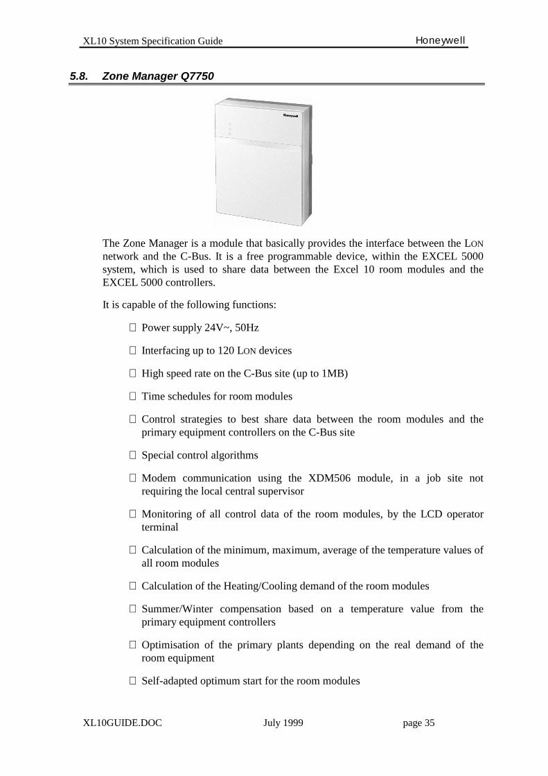
5.8. Zone Manager Q7750
The Zone Manager is a module that basically provides the interface between the LON
network and the C-Bus. It is a free programmable device, within the EXCEL 5000system, which is used to share data between the Excel 10 room modules and theEXCEL 5000 controllers.
It is capable of the following functions:
∗ Power supply 24V~, 50Hz
∗ Interfacing up to 120 LON devices
∗ High speed rate on the C-Bus site (up to 1MB)
∗ Time schedules for room modules
∗ Control strategies to best share data between the room modules and theprimary equipment controllers on the C-Bus site
∗ Special control algorithms
∗ Modem communication using the XDM506 module, in a job site notrequiring the local central supervisor
∗ Monitoring of all control data of the room modules, by the LCD operatorterminal
∗ Calculation of the minimum, maximum, average of the temperature values ofall room modules
∗ Calculation of the Heating/Cooling demand of the room modules
∗ Summer/Winter compensation based on a temperature value from theprimary equipment controllers
∗ Optimisation of the primary plants depending on the real demand of theroom equipment
∗ Self-adapted optimum start for the room modules
XL10 System Specification Guide Honeywell
XL10GUIDE.DOC July 1999 page 36
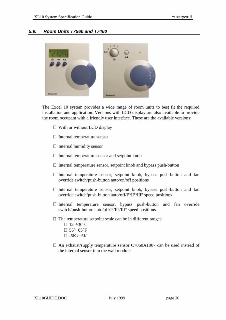
5.9. Room Units T7560 and T7460
The Excel 10 system provides a wide range of room units to best fit the requiredinstallation and application. Versions with LCD display are also available to providethe room occupant with a friendly user interface. These are the available versions:
∗ With or without LCD display
∗ Internal temperature sensor
∗ Internal humidity sensor
∗ Internal temperature sensor and setpoint knob
∗ Internal temperature sensor, setpoint knob and bypass push-button
∗ Internal temperature sensor, setpoint knob, bypass push-button and fanoverride switch/push-button auto/on/off positions
∗ Internal temperature sensor, setpoint knob, bypass push-button and fanoverride switch/push-button auto/off/I°/II°/III° speed positions
∗ Internal temperature sensor, bypass push-button and fan overrideswitch/push-button auto/off/I°/II°/III° speed positions
∗ The temperature setpoint scale can be in different ranges:⇒ 12°÷30°C⇒ 55°÷85°F⇒ -5K÷+5K
∗ An exhaust/supply temperature sensor C7068A1007 can be used instead ofthe internal sensor into the wall module