excavation safety program pursuant to 29 cfr 1926 , subpart p · excavation safety program pursuant...
TRANSCRIPT

Arizona State University
Excavation Safety Program Pursuant to 29 CFR 1926, Subpart P
Department of Environmental Health & Safety February 2009

1
TABLE OF CONTENTS
Introduction ..............................................................................................................2
Purpose ..............................................................................................................2
Scope and Application .................................................................................................2
Responsibilities ...........................................................................................................2
Program Administrator ......................................................................................2
Supervisors .......................................................................................................3
Employees ........................................................................................................3
1926.650, Scope, application, and definitions applicable to this subpart s ...........................3
1926.651, Specific excavation requirements ...................................................................6
1926.652, Requirements for protective systems ..............................................................9
Appendix A: Soil Classification ......................................................................................14
Appendix B: Sloping and Benching ...............................................................................20
Appendix C: Timber Shoring for Trenches .....................................................................29
Appendix D: Aluminum Hydraulic Shoring for Trenches .................................................53
Appendix E: Alternatives to Timber Shoring ..................................................................65
Appendix F: Selection of Protective Systems .................................................................67
Appendix G: Excavation Inspection Form ......................................................................71

2
INTRODUCTION
Under the U.S. Department of Labor Occupational Safety and Health Administration’s (OSHA) employers are required to establish and implement procedures for safety during excavations. The Excavation Standard, 29 CFR §1926 Subpart P is designed to minimize employee exposure to hazardous conditions during excavations. This program when followed meets the requirements of §1926 Subpart P as the entire standard is incorporated into this document.
PURPOSE
Arizona State University Department of Environmental Health & Safety (EH&S) has determined that some employees may be required to work in excavations and/or actually prepare trenches and shoring involved in excavations. The purpose of this program is to ensure compliance with OSHA regulations and to protect employees from the hazards associated with excavation activities.
SCOPE AND APPLICATION
This program applies to all ASU employees who may be required to excavate soils or work in excavation sites at all ASU campuses.
RESPONSIBILITIES
Designated Program Competent Person: Dan Meraz, ASU Safety Manager
The EH&S Designated Competent Person is responsible for administering the excavation safety program and has the authority to make decisions and implement changes, as necessary. Duties include: Identifying work areas, processes, or tasks that require employees to complete
excavation training; Providing technical assistance to university departments and units in their effort to
address the mandates established by the OSHA Excavation Standard;
Evaluating hazards to determine the type of engineering control required for excavation activities involving ASU employees;
Arranging and/or conducting required training; Identifying, training and designating other competent persons for the purposes of this
program;
Establishing periodic inspection schedules of those workplaces/conditions that require excavations to determine exposure and/or changing situations; and
Maintaining records required by this program.
3
Supervisors – Department Dean, Chair, Director, or designee
Each Department Supervisor or designee is responsible for the following: ensuring that excavation activities involving ASU employees are reviewed with a
designated competent person; ensuring that employees participate in required training; and
ensuring that all requirements of this program are followed by employees under their control.
Employees
Each employee must comply with the requirements of this program including participation in any required training by the designated competent person. Training EH&S or other qualified individual or company will provide training to affected employees as required in this program. DOCUMENTATION AND RECORD-KEEPING A written copy of this program and the OSHA standard are kept in EH&S and available to all employees. Additionally, employees may access the written program through the ASU EH&S website. An inspection form is available as Appendix G.
SCOPE, APPLICATION, AND DEFINITIONS APPLICABLE TO THIS SUBPART
1926.650(a) Scope and application. This subpart applies to all Arizona State University (ASU) open excavations made in the earth's surface. Excavations are defined to include trenches.
1926.650(b) DEFINITIONS APPLICABLE TO THIS SUBPART
"Accepted engineering practices" means those requirements which are compatible with standards of practice required by a registered professional engineer.
"Aluminum Hydraulic Shoring" means a pre-engineered shoring system comprised of aluminum
hydraulic cylinders (crossbraces) used in conjunction with vertical rails (uprights) or horizontal
rails (wales). Such system is designed specifically to support the sidewalls of an excavation and prevent cave-ins.
"Bell-bottom pier hole" means a type of shaft or footing excavation, the bottom of which is made larger than the cross section above to form a belled shape.

4
"Benching (Benching system)" means a method of protecting employees from cave-ins by
excavating the sides of an excavation to form one or a series of horizontal levels or steps, usually with vertical or near-vertical surfaces between levels.
"Cave-in" means the separation of a mass of soil or rock material from the side of an
excavation, or the loss of soil from under a trench shield or support system, and its sudden
movement into the excavation, either by falling or sliding, in sufficient quantity so that it could entrap, bury, or otherwise injure and immobilize a person.
"Competent person" means one who is capable of identifying existing and predictable hazards
in the surroundings, or working conditions which are unsanitary, hazardous, or dangerous to
employees, and who has authorization to take prompt corrective measures to eliminate them.
"Cross braces" mean the horizontal members of a shoring system installed perpendicular to the sides of the excavation, the ends of which bear against either uprights or wales.
"Excavation" means any man-made cut, cavity, trench, or depression in an earth surface, formed by earth removal.
"Faces" or "sides" means the vertical or inclined earth surfaces formed as a result of excavation work.
"Failure" means the breakage, displacement, or permanent deformation of a structural member
or connection so as to reduce its structural integrity and its supportive capabilities.
"Hazardous atmosphere" means an atmosphere which by reason of being explosive, flammable,
poisonous, corrosive, oxidizing, irritating, oxygen deficient, toxic, or otherwise harmful, may cause death, illness, or injury.
"Kickout" means the accidental release or failure of a cross brace.
"Protective system" means a method of protecting employees from cave-ins, from material that
could fall or roll from an excavation face or into an excavation, or from the collapse of adjacent
structures. Protective systems include support systems, sloping and benching systems, shield
systems, and other systems that provide the necessary protection.
"Ramp" means an inclined walking or working surface that is used to gain access to one point from another, and is constructed from earth or from structural materials such as steel or wood.
"Registered Professional Engineer" means a person who is registered as a professional engineer
in the state where the work is to be performed. However, a professional engineer, registered in
any state is deemed to be a "registered professional engineer" within the meaning of this
standard when approving designs for "manufactured protective systems" or "tabulated data" to be used in interstate commerce.
"Sheeting" means the members of a shoring system that retain the earth in position and in turn are supported by other members of the shoring system.
"Shield (Shield system)" means a structure that is able to withstand the forces imposed on it by
a cave-in and thereby protect employees within the structure. Shields can be permanent
structures or can be designed to be portable and moved along as work progresses. Additionally,

5
shields can be either premanufactured or job-built in accordance with 1926.652(c)(3) or (c)(4). Shields used in trenches are usually referred to as "trench boxes" or "trench shields."
"Shoring (Shoring system)" means a structure such as a metal hydraulic, mechanical or timber
shoring system that supports the sides of an excavation and which is designed to prevent cave-
ins.
"Sides". See "Faces."
"Sloping (Sloping system)" means a method of protecting employees from cave-ins by
excavating to form sides of an excavation that are inclined away from the excavation so as to
prevent cave-ins. The angle of incline required to prevent a cave-in varies with differences in
such factors as the soil type, environmental conditions of exposure, and application of
surcharge loads.
"Stable rock" means natural solid mineral material that can be excavated with vertical sides and
will remain intact while exposed. Unstable rock is considered to be stable when the rock
material on the side or sides of the excavation is secured against caving-in or movement by
rock bolts or by another protective system that has been designed by a registered professional
engineer.
"Structural ramp" means a ramp built of steel or wood, usually used for vehicle access. Ramps made of soil or rock are not considered structural ramps.
"Support system" means a structure such as underpinning, bracing, or shoring, which provides support to an adjacent structure, underground installation, or the sides of an excavation.
"Tabulated data" means tables and charts approved by a registered professional engineer and used to design and construct a protective system.
"Trench (Trench excavation)" means a narrow excavation (in relation to its length) made below
the surface of the ground. In general, the depth is greater than the width, but the width of a
trench (measured at the bottom) is not greater than 15 feet (4.6 m). If forms or other
structures are installed or constructed in an excavation so as to reduce the dimension
measured from the forms or structure to the side of the excavation to 15 feet (4.6 m) or less
(measured at the bottom of the excavation), the excavation is also considered to be a trench.
"Uprights" means the vertical members of a trench shoring system placed in contact with the
earth and usually positioned so that individual members do not contact each other. Uprights
placed so that individual members are closely spaced, in contact with or interconnected to each other, are often called "sheeting."
"Wales" means horizontal members of a shoring system placed parallel to the excavation face
whose sides bear against the vertical members of the shoring system or earth.
1926.651(a) Surface encumbrances. All surface encumbrances that are located so as to create a hazard to employees shall be removed or supported, as necessary, to safeguard employees.

6
1926.651(b) UNDERGROUND INSTALLATIONS
1926.651(b)(1) The estimated location of utility installations, such as sewer, telephone, fuel,
electric, water lines, or any other underground installations that reasonably may be expected to be encountered during excavation work, shall be determined prior to opening an excavation.
1926.651(b)(2) Utility companies or owners shall be contacted within established or customary
local response times, advised of the proposed work, and asked to establish the location of the
utility underground installations prior to the start of actual excavation. When utility companies
or owners cannot respond to a request to locate underground utility installations within 24
hours (unless a longer period is required by state or local law), or cannot establish the exact
location of these installations, the employer may proceed, provided the employer does so with
caution, and provided detection equipment or other acceptable means to locate utility installations are used.
1926.651(b)(3) When excavation operations approach the estimated location of underground
installations, the exact location of the installations shall be determined by safe and acceptable
means.
1926.651(b)(4) While the excavation is open, underground installations shall be protected, supported or removed as necessary to safeguard employees.
1926.651(c) ACCESS AND EGRESS
1926.651(c)(1) Structural ramps.
1926.651(c)(1)(i) Structural ramps that are used solely by employees as a means of access or
egress from excavations shall be designed by a competent person. Structural ramps used for
access or egress of equipment shall be designed by a competent person qualified in structural
design, and shall be constructed in accordance with the design.
1926.651(c)(1)(ii) Ramps and runways constructed of two or more structural members shall have the structural members connected together to prevent displacement.
1926.651(c)(1)(iii) Structural members used for ramps and runways shall be of uniform thickness.
1926.651(c)(1)(iv) Cleats or other appropriate means used to connect runway structural
members shall be attached to the bottom of the runway or shall be attached in a manner to
prevent tripping.
1926.651(c)(1)(v) Structural ramps used in lieu of steps shall be provided with cleats or other
surface treatments o the top surface to prevent slipping.
1926.651(c)(2) Means of egress from trench excavations. A stairway, ladder, ramp or other
safe means of egress shall be located in trench excavations that are 4 feet (1.22 m) or more in depth so as to require no more than 25 feet (7.62 m) of lateral travel for employees.
1926.651(d) Exposure to vehicular traffic. Employees exposed to public vehicular traffic shall be
provided with, and shall wear, warning vests or other suitable garments marked with or made
of reflectorized or high-visibility material.

7
1926.651(e) Exposure to falling loads. No employee shall be permitted underneath loads
handled by lifting or digging equipment. Employees shall be required to stand away from any
vehicle being loaded or unloaded to avoid being struck by any spillage or falling materials.
Operators may remain in the cabs of vehicles being loaded or unloaded when the vehicles are
equipped, in accordance with 1926.601(b)(6), to provide adequate protection for the operator during loading and unloading operations.
1926.651(f) Warning system for mobile equipment. When mobile equipment is operated
adjacent to an excavation, or when such equipment is required to approach the edge of an
excavation, and the operator does not have a clear and direct view of the edge of the
excavation, a warning system shall be utilized such as barricades, hand or mechanical signals, or stop logs. If possible, the grade should be away from the excavation.
1926.651(g) HAZARDOUS ATMOSPHERES
1926.651(g)(1) Testing and controls. In addition to the requirements set forth in subparts D
and E of this part (29 CFR 1926.50 - 1926.107) to prevent exposure to harmful levels of
atmospheric contaminants and to assure acceptable atmospheric conditions, the following requirements shall apply:
1926.651(g)(1)(i) Where oxygen deficiency (atmospheres containing less than 19.5 percent
oxygen) or a hazardous atmosphere exists or could reasonably be expected to exist, such as in
excavations in landfill areas or excavations in areas where hazardous substances are stored
nearby, the atmospheres in the excavation shall be tested before employees enter excavations greater than 4 feet (1.22 m) in depth.
1926.651(g)(1)(ii) Adequate precautions shall be taken to prevent employee exposure to
atmospheres containing less than 19.5 percent oxygen and other hazardous atmospheres.
These precautions include providing proper respiratory protection or ventilation in accordance with subparts D and E of this part respectively.
1926.651(g)(1)(iii) Adequate precaution shall be taken such as providing ventilation, to prevent
employee exposure to an atmosphere containing a concentration of a flammable gas in excess of 20 percent of the lower flammable limit of the gas.
1926.651(g)(1)(iv) When controls are used that are intended to reduce the level of atmospheric
contaminants to acceptable levels, testing shall be conducted as often as necessary to ensure that the atmosphere remains safe.
Any work under the conditions of 1926.651(g)(1) requires either a confined space
entry permit as identified in the ASU Confined Space Entry Program available
http://www.asu.edu/uagc/EHS/documents/asu_confined_space_entry_plan.pdf at
or a documented safety plan approved by the Facilities Management Safety Program Manager.
1926.651(g)(2) EMERGENCY RESCUE EQUIPMENT
1926.651(g)(2)(i) Emergency rescue equipment, such as breathing apparatus, a safety harness
and line, or a basket stretcher, shall be readily available where hazardous atmospheric
conditions exist or may reasonably be expected to develop during work in an excavation. This
equipment shall be attended when in use.

8
1926.651(g)(2)(ii) Employees entering bell-bottom pier holes, or other similar deep and
confined footing excavations, shall wear a harness with a lifeline securely attached to it. The
lifeline shall be separate from any line used to handle materials, and shall be individually
attended at all times while the employee wearing the lifeline is in the excavation.
1926.651(h) PROTECTION FROM HAZARDS ASSOCIATED WITH WATER ACCUMULATION
1926.651(h)(1) Employees shall not work in excavations in which there is accumulated water,
or in excavations in which water is accumulating, unless adequate precautions have been taken
to protect employees against the hazards posed by water accumulation. The precautions
necessary to protect employees adequately vary with each situation, but could include special
support or shield systems to protect from cave-ins, water removal to control the level of accumulating water, or use of a safety harness and lifeline.
1926.651(h)(2) If water is controlled or prevented from accumulating by the use of water
removal equipment, the water removal equipment and operations shall be monitored by a competent person to ensure proper operation.
1926.651(h)(3) If excavation work interrupts the natural drainage of surface water (such as
streams), diversion ditches, dikes, or other suitable means shall be used to prevent surface
water from entering the excavation and to provide adequate drainage of the area adjacent to
the excavation. Excavations subject to runoff from heavy rains will require an inspection by a competent person and compliance with paragraphs (h)(1) and (h)(2) of this section.
1926.651(i) STABILITY OF ADJACENT STRUCTURES
1926.651(i)(1) Where the stability of adjoining buildings, walls, or other structures is
endangered by excavation operations, support systems such as shoring, bracing, or
underpinning shall be provided to ensure the stability of such structures for the protection of employees.
1926.651(i)(2) Excavation below the level of the base or footing of any foundation or retaining
wall that could be reasonably expected to pose a hazard to employees shall not be permitted
except when:
1926.651(i)(2)(i) A support system, such as underpinning, is provided to ensure the safety of employees and the stability of the structure; or
1926.651(i)(2)(ii) The excavation is in stable rock; or
1926.651(i)(2)(iii) A registered professional engineer has approved the determination that the
structure is sufficiently removed from the excavation so as to be unaffected by the excavation activity; or
1926.651(i)(2)(iv) A registered professional engineer has approved the determination that such
excavation work will not pose a hazard to employees.
1926.651(i)(3) Sidewalks, pavements and appurtenant structure shall not be undermined
unless a support system or another method of protection is provided to protect employees from the possible collapse of such structures.

9
1926.651(j) PROTECTION OF EMPLOYEES FROM LOOSE ROCK OR SOIL
1926.651(j)(1) Adequate protection shall be provided to protect employees from loose rock or
soil that could pose a hazard by falling or rolling from an excavation face. Such protection shall
consist of scaling to remove loose material; installation of protective barricades at intervals as
necessary on the face to stop and contain falling material; or other means that provide equivalent protection.
1926.651(j)(2) Employees shall be protected from excavated or other materials or equipment
that could pose a hazard by falling or rolling into excavations. Protection shall be provided by
placing and keeping such materials or equipment at least 2 feet (.61 m) from the edge of
excavations, or by the use of retaining devices that are sufficient to prevent materials or equipment from falling or rolling into excavations, or by a combination of both if necessary.
1926.651(k) INSPECTIONS
1926.651(k)(1) Daily inspections of excavations, the adjacent areas, and protective systems
shall be made by a competent person for evidence of a situation that could result in possible
cave-ins, indications of failure of protective systems, hazardous atmospheres, or other
hazardous conditions. An inspection shall be conducted by the competent person prior to the
start of work and as needed throughout the shift. Inspections shall also be made after every
rainstorm or other hazard increasing occurrence. These inspections are only required when employee exposure can be reasonably anticipated.
1926.651(k)(2) Where the competent person finds evidence of a situation that could result in a
possible cave-in, indications of failure of protective systems, hazardous atmospheres, or other
hazardous conditions, exposed employees shall be removed from the hazardous area until the necessary precautions have been taken to ensure their safety.
1926.651(l) FALL PROTECTION
1926.651(l)(1) Walkways shall be provided where employees or equipment are required or
permitted to cross over excavations. Guardrails which comply with 1926.502(b) shall be
provided where walkways are 6 feet (1.8 m) or more above lower levels.
1926.652(a) PROTECTION OF EMPLOYEES IN EXCAVATIONS
1926.652(a)(1) Each employee in an excavation shall be protected from cave-ins by an
adequate protective system designed in accordance with paragraph (b) or (c) of this section
except when:
1926.652(a)(1)(i) Excavations are made entirely in stable rock; or
1926.652(a)(1)(ii) Excavations are less than 5 feet (1.52 m) in depth and examination of the
ground by a competent person provides no indication of a potential cave-in.
1926.652(a)(2) Protective systems shall have the capacity to resist without failure all loads that
are intended or could reasonably be expected to be applied or transmitted to the system.
1926.652(b) Design of sloping and benching systems. The slopes and configurations of sloping
and benching systems shall be selected and constructed by the employer or his designee and

10
shall be in accordance with the requirements of paragraph (b)(1); or, in the alternative,
paragraph (b)(2); or, in the alternative, paragraph (b)(3); or, in the alternative, paragraph
(b)(4), as follows:
1926.652(b)(1) Option (1) - Allowable configurations and slopes.
1926.652(b)(1)(i) Excavations shall be sloped at an angle not steeper than one and one-half
horizontal to one vertical (34 degrees measured from the horizontal), unless the employer uses
one of the other options listed below.
1926.652(b)(1)(ii) Slopes specified in paragraph (b)(1)(i) of this section, shall be excavated to
form configurations that are in accordance with the slopes shown for Type C soil in Appendix B
to this subpart.
1926.652(b)(2) Option (2) - Determination of slopes and configurations using Appendices A and
B. Maximum allowable slopes, and allowable configurations for sloping and benching systems,
shall be determined in accordance with the conditions and requirements set forth in appendices
A and B to this subpart.
1926.652(b)(3) Option (3) - Designs using other tabulated data.
1926.652(b)(3)(i) Designs of sloping or benching systems shall be selected from and in
accordance with tabulated data, such as tables and charts.
1926.652(b)(3)(ii) The tabulated data shall be in written form and shall include all of the
following:
1926.652(b)(3)(ii)(A) Identification of the parameters that affect the selection of a sloping or
benching system drawn from such data;
1926.652(b)(3)(ii)(B) Identification of the limits of use of the data, to include the magnitude
and configuration of slopes determined to be safe;
1926.652(b)(3)(ii)(C) Explanatory information as may be necessary to aid the user in making a
correct selection of a protective system from the data.
1926.652(b)(3)(iii) At least one copy of the tabulated data which identifies the registered
professional engineer who approved the data, shall be maintained at the jobsite during
construction of the protective system. After that time the data may be stored off the jobsite,
but a copy of the data shall be made available to the Secretary upon request.
1926.652(b)(4) Option (4) - Design by a registered professional engineer.
1926.652(b)(4)(i) Sloping and benching systems not utilizing Option (1) or Option (2) or Option
(3) under paragraph (b) of this section shall be approved by a registered professional engineer.
1926.652(b)(4)(ii) Designs shall be in written form and shall include at least the following:
1926.652(b)(4)(ii)(A) The magnitude of the slopes that were determined to be safe for the
particular project;
1926.652(b)(4)(ii)(B) The configurations that were determined to be safe for the particular

11
project;
1926.652(b)(4)(ii)(C) The identity of the registered professional engineer approving the design.
1926.652(b)(4)(iii) At least one copy of the design shall be maintained at the jobsite while the
slope is being constructed. After that time the design need not be at the jobsite, but a copy
shall be made available to the Secretary upon request.
1926.652(c) Design of support systems, shield systems, and other protective systems. Designs
of support systems, shield systems, and other protective systems shall be selected and
constructed by the employer or his designee and shall be in accordance with the requirements
of paragraph (c)(1); or, in the alternative, paragraph (c)(2); or, in the alternative, paragraph
(c)(3); or, i the alternative, paragraph (c)(4) as follows:
1926.652(c)(1) Option (1) - Designs using appendices A, C and D. Designs for timber shoring in
trenches shall be determined in accordance with the conditions and requirements set forth in
appendices A and C to this subpart. Designs for aluminum hydraulic shoring shall be in
accordance with paragraph (c)(2) of this section, but if manufacturer's tabulated data cannot be
utilized, designs shall be in accordance with appendix D.
1926.652(c)(2) Option (2) - Designs Using Manufacturer's Tabulated Data.
1926.652(c)(2)(i) Design of support systems, shield systems, or other protective systems that
are drawn from manufacturer's tabulated data shall be in accordance with all specifications,
recommendations, and limitations issued or made by the manufacturer.
1926.652(c)(2)(ii) Deviation from the specifications, recommendations, and limitations issued
or made by the manufacturer shall only be allowed after the manufacturer issues specific
written approval.
1926.652(c)(2)(iii) Manufacturer's specifications, recommendations, and limitations, and
manufacturer's approval to deviate from the specifications, recommendations, and limitations
shall be in written form at the jobsite during construction of the protective system. After that
time this data may be stored off the jobsite, but a copy shall be made available to the
Secretary upon request.
1926.652(c)(3) Option (3) - Designs using other tabulated data.
1926.652(c)(3)(i) Designs of support systems, shield systems, or other protective systems shall
be selected from and be in accordance with tabulated data, such as tables and charts.
1926.652(c)(3)(ii) The tabulated data shall be in written form and include all of the following:
1926.652(c)(3)(ii)(A) Identification of the parameters that affect the selection of a protective
system drawn from such data;
1926.652(c)(3)(ii)(B) Identification of the limits of use of the data;
1926.652(c)(3)(ii)(C) Explanatory information as may be necessary to aid the user in making a
correct selection of a protective system from the data.
1926.652(c)(3)(iii) At least one copy of the tabulated data, which identifies the registered
professional engineer who approved the data, shall be maintained at the jobsite during
12
construction of the protective system. After that time the data may be stored off the jobsite,
but a copy of the data shall be made available to the Secretary upon request.
1926.652(c)(4) Option (4) - Design by a registered professional engineer.
1926.652(c)(4)(i) Support systems, shield systems, and other protective systems not utilizing
Option 1, Option 2 or Option 3, above, shall be approved by a registered professional engineer.
1926.652(c)(4)(ii) Designs shall be in written form and shall include the following:
1926.652(c)(4)(ii)(A) A plan indicating the sizes, types, and configurations of the materials to
be used in the protective system; and
1926.652(c)(4)(ii)(B) The identify of the registered professional engineer approving the design.
1926.652(c)(4)(iii) At least one copy of the design shall be maintained at the jobsite during
construction of the protective system. After that time, the design may be stored off the jobsite,
but a copy of the design shall be made available to the Secretary upon request.
1926.652(d) MATERIALS AND EQUIPMENT
1926.652(d)(1) Materials and equipment used for protective systems shall be free from
damage or defects that might impair their proper function.
1926.652(d)(2) Manufactured materials and equipment used for protective systems shall be
used and maintained in a manner that is consistent with the recommendations of the
manufacturer, and in a manner that will prevent employee exposure to hazards.
1926.652(d)(3) When material or equipment that is used for protective systems is damaged, a
competent person shall examine the material or equipment and evaluate its suitability for
continued use. If the competent person cannot assure the material or equipment is able to
support the intended loads or is otherwise suitable for safe use, then such material or
equipment shall be removed from service, and shall be evaluated and approved by a registered
professional engineer before being returned to service.
1926.652(e) INSTALLATION AND REMOVAL OF SUPPORT
1926.652(e)(1) General.
1926.652(e)(1)(i) Members of support systems shall be securely connected together to prevent
sliding, falling, kick outs, or other predictable failure.
1926.652(e)(1)(ii) Support systems shall be installed and removed in a manner that protects
employees from cave-ins, structural collapses, or from being struck by members of the support
system.
1926.652(e)(1)(iii) Individual members of support systems shall not be subjected to loads
exceeding those which those members were designed to withstand.
1926.652(e)(1)(iv) Before temporary removal of individual members begins, additional
precautions shall be taken to ensure the safety of employees, such as installing other structural
members to carry the loads imposed on the support system.

13
1926.652(e)(1)(v) Removal shall begin at, and progress from, the bottom of the excavation.
Members shall be released slowly so as to note any indication of possible failure of the
remaining members of the structure or possible cave-in of the sides of the excavation.
1926.652(e)(1)(vi) Backfilling shall progress together with the removal of support systems from
excavations.
1926.652(e)(2) Additional requirements for support systems for trench excavations.
1926.652(e)(2)(i) Excavation of material to a level no greater than 2 feet (.61 m) below the
bottom of the members of a support system shall be permitted, but only if the system is
designed to resist the forces calculated for the full depth of the trench, and there are no
indications while the trench is open of a possible loss of soil from behind or below the bottom of
the support system.
1926.652(e)(2)(ii) Installation of a support system shall be closely coordinated with the
excavation of trenches.
1926.652(f) Sloping and benching systems. Employees shall not be permitted to work on the
faces of sloped or benched excavations at levels above other employees except when
employees at the lower levels are adequately protected from the hazard of falling, rolling, or
sliding material or equipment.
1926.652(g) SHIELD SYSTEMS
1926.652(g)(1) General.
1926.652(g)(1)(i) Shield systems shall not be subjected to loads exceeding those which the
system was designed to withstand.
1926.652(g)(1)(ii) Shields shall be installed in a manner to restrict lateral or other hazardous
movement of the shield in the event of the application of sudden lateral loads.
1926.652(g)(1)(iii) Employees shall be protected from the hazard of cave-ins when entering or
exiting the areas protected by shields.
1926.652(g)(1)(iv) Employees shall not be allowed in shields when shields are being installed,
removed, or moved vertically.
1926.652(g)(2) Additional requirement for shield systems used in trench excavations.
Excavations of earth material to a level not greater than 2 feet (.61 m) below the bottom of a
shield shall be permitted, but only if the shield is designed to resist the forces calculated for the
full depth of the trench, and there are no indications while the trench is open of a possible loss
of soil from behind or below the bottom of the shield.

14
Appendix A
Soil Classification

15
(a) Scope and application - (1) Scope. This appendix describes a method of classifying soil and
rock deposits based on site and environmental conditions, and on the structure and composition
of the earth deposits. The appendix contains definitions, sets forth requirements, and describes
acceptable visual and manual tests for use in classifying soils.
(2) Application. This appendix applies when a sloping or benching system is designed in
accordance with the requirements set forth in 1926.652(b)(2) as a method of protection for
employees from cave-ins. This appendix also applies when timber shoring for excavations is
designed as a method of protection from cave-ins in accordance with appendix C to subpart P of
part 1926, and when aluminum hydraulic shoring is designed in accordance with appendix D.
This Appendix also applies if other protective systems are designed and selected for use from
data prepared in accordance with the requirements set forth in 1926.652(c), and the use of the
data is predicated on the use of the soil classification system set forth in this appendix.
(b) Definitions. The definitions and examples given below are based on, in whole or in part, the
following; American Society for Testing Materials (ASTM) Standards D653-85 and D2488; The
Unified Soils Classification System; The U.S. Department of Agriculture (USDA) Textural Classification Scheme; and The National Bureau of Standards Report BSS-121.
"Cemented soil" means a soil in which the particles are held together by a chemical agent,
such as calcium carbonate, such that a hand-size sample cannot be crushed into powder or
individual soil particles by finger pressure.
"Cohesive soil" means clay (fine grained soil), or soil with a high clay content, which has
cohesive strength. Cohesive soil does not crumble, can be excavated with vertical side slopes,
and is plastic when moist. Cohesive soil is hard to break up when dry, and exhibits significant
cohesion when submerged. Cohesive soils include clayey silt, sandy clay,
silty clay, clay and organic clay.
"Dry soil" means soil that does not exhibit visible signs of moisture content.
"Fissured" means a soil material that has a tendency to break along definite planes of fracture
with little resistance, or a material that exhibits open cracks, such as tension cracks, in an
exposed surface.
"Granular soil" means gravel, sand, or silt (coarse grained soil) with little or no clay content.
Granular soil has no cohesive strength. Some moist granular soils exhibit apparent cohesion.
Granular soil cannot be molded when moist and crumbles easily when dry.
"Layered system" means two or more distinctly different soil or rock types arranged in layers.
Micaceous seams or weakened planes in rock or shale are considered layered.
"Moist soil" means a condition in which a soil looks and feels damp. Moist cohesive soil can
easily be shaped into a ball and rolled into small diameter threads before crumbling. Moist
granular soil that contains some cohesive material will exhibit signs of cohesion between
particles.
"Plastic" means a property of a soil which allows the soil to be deformed or molded without
cracking, or appreciable volume change.

16
"Saturated soil" means a soil in which the voids are filled with water. Saturation does not
require flow. Saturation, or near saturation, is necessary for the proper use of instruments such
as a pocket penetrometer or sheer vane.
"Soil classification system" means, for the purpose of this subpart, a method of categorizing soil
and rock deposits in a hierarchy of Stable Rock, Type A, Type B, and Type C, in decreasing
order of stability. The categories are determined based on an analysis of the properties and
performance characteristics of the deposits and the characteristics of the
deposits and the environmental conditions of exposure.
"Stable rock" means natural solid mineral matter that can be excavated with vertical sides and
remain intact while exposed.
"Submerged soil" means soil which is underwater or is free seeping.
"TYPE A" MEANS
cohesive soils with an unconfined, compressive strength of 1.5 ton per square foot (tsf) (144
kPa) or greater. Examples of cohesive soils are: clay, silty clay, sandy clay, clay loam and, in
some cases, silty clay loam and sandy clay loam. Cemented soils such as cliché
and hardpan are also considered Type A.
However, no soil is Type A if:
(i) The soil is fissured; or
(ii) The soil is subject to vibration from heavy traffic, pile driving, or similar effects; or
(iii) The soil has been previously disturbed; or
(iv) The soil is part of a sloped, layered system where the layers dip into the excavation on a
slope of four horizontal to one vertical (4H:1V) or greater; or
(v) The material is subject to other factors that would require it to be classified as a less stable
material.
"TYPE B" MEANS
(i) Cohesive soil with an unconfined compressive strength greater than 0.5 tsf (48 kPa) but
less than 1.5 tsf (144 kPa); or
(ii) Granular cohesionless soils including: angular gravel (similar to crushed rock), silt, silt
loam, sandy loam and, in some cases, silty clay loam and sandy clay loam.
(iii) Previously disturbed soils except those which would otherwise be classed as Type C soil.
(iv) Soil that meets the unconfined compressive strength or cementation requirements for
Type A, but is fissured or subject to vibration; or
(v) Dry rock that is not stable; or
(vi) Material that is part of a sloped, layered system where the layers dip into the excavation
on a slope less steep than four horizontal to one vertical (4H:1V), but only if the material
would otherwise be classified as Type B.
"TYPE C" MEANS
(i) Cohesive soil with an unconfined compressive strength of 0.5 tsf (48 kPa) or less; or
(ii) Granular soils including gravel, sand, and loamy sand; or
(iii) Submerged soil or soil from which water is freely seeping; or
(iv) Submerged rock that is not stable, or
(v) Material in a sloped, layered system where the layers dip into the excavation or a slope of
four horizontal to one vertical (4H:1V) or steeper.
"Unconfined compressive strength" means the load per unit area at which a soil will fail in

17
compression. It can be determined by laboratory testing, or estimated in the field using a
pocket penetrometer, by thumb penetration tests, and other methods.
"Wet soil" means soil that contains significantly more moisture than moist soil, but in such a
range of values that cohesive material will slump or begin to flow when vibrated. Granular
material that would exhibit cohesive properties when moist will lose those cohesive properties
when wet.
(c) Requirements - (1) Classification of soil and rock deposits. Each soil and rock deposit shall
be classified by a competent person as Stable Rock, Type A, Type B, or Type C in accordance with the definitions set forth in paragraph (b) of this appendix.
(2) Basis of classification. The classification of the deposits shall be made based on the results
of at least one visual and at least one manual analysis. Such analyses shall be conducted by a
competent person using tests described in paragraph (d) below, or in other recognized methods
of soil classification and testing such as those adopted by the American Society for Testing Materials, or the U.S. Department of Agriculture textural classification system.
(3) Visual and manual analyses. The visual and manual analyses, such as those noted as being
acceptable in paragraph (d) of this appendix, shall be designed and conducted to provide
sufficient quantitative and qualitative information as may be necessary to identify properly the properties, factors, and conditions affecting the classification of the deposits.
(4) Layered systems. In a layered system, the system shall be classified in accordance with its
weakest layer. However, each layer may be classified individually where a more stable layer lies under a less stable layer.
(5) Reclassification. If, after classifying a deposit, the properties, factors, or conditions affecting
its classification change in any way, the changes shall be evaluated by a competent person. The deposit shall be reclassified as necessary to reflect the changed circumstances.
(d) Acceptable visual and manual tests. - (1) Visual tests. Visual analysis is conducted to
determine qualitative information regarding the excavation site in general, the soil adjacent to
the excavation, the soil forming the sides of the open excavation, and the soil taken as samples
from excavated material.
(i) Observe samples of soil that are excavated and soil in the sides of the excavation. Estimate
the range of particle sizes and the relative amounts of the particle sizes. Soil that is primarily
composed of fine-grained material material is cohesive material. Soil composed primarily of coarse-grained sand or gravel is granular material.
(ii) Observe soil as it is excavated. Soil that remains in clumps when excavated is cohesive. Soil
that breaks up easily and does not stay in clumps is granular.
(iii) Observe the side of the opened excavation and the surface area adjacent to the excavation.
Crack-like openings such as tension cracks could indicate fissured material. If chunks of soil
spall off a vertical side, the soil could be fissured. Small spalls are evidence of moving ground and are indications of potentially hazardous situations.
(iv) Observe the area adjacent to the excavation and the excavation itself for evidence of
existing utility and other underground structures, and to identify previously disturbed soil.

18
(v) Observed the opened side of the excavation to identify layered systems. Examine layered
systems to identify if the layers slope toward the excavation. Estimate the degree of slope of the layers.
(vi) Observe the area adjacent to the excavation and the sides of the opened excavation for
evidence of surface water, water seeping from the sides of the excavation, or the location of the level of the water table.
(vii) Observe the area adjacent to the excavation and the area within the excavation for sources of vibration that may affect the stability of the excavation face.
(2) Manual tests. Manual analysis of soil samples is conducted to determine quantitative as well
as qualitative properties of soil and to provide more information in order to classify soil
properly.
(i) Plasticity. Mold a moist or wet sample of soil into a ball and attempt to roll it into threads as
thin as 1/8-inch in diameter. Cohesive material can be successfully rolled into threads without
crumbling. For example, if at least a two inch (50 mm) length of 1/8-inch thread can be held on one end without tearing, the soil is cohesive.
(ii) Dry strength. If the soil is dry and crumbles on its own or with moderate pressure into
individual grains or fine powder, it is granular (any combination of gravel, sand, or silt). If the
soil is dry and falls into clumps which break up into smaller clumps, but the smaller clumps can
only be broken up with difficulty, it may be clay in any combination with gravel, sand or silt. If
the dry soil breaks into clumps which do not break up into small clumps and which can only be
broken with difficulty, and there is no visual indication the soil is fissured, the soil may be considered unfissured.
(iii) Thumb penetration. The thumb penetration test can be used to estimate the unconfined
compressive strength of cohesive soils. (This test is based on the thumb penetration test
described in American Society for Testing and Materials (ASTM) Standard designation D2488 -
"Standard Recommended Practice for Description of Soils (Visual - Manual Procedure).") Type A
soils with an unconfined compressive strength of 1.5 tsf can be readily indented by the thumb;
however, they can be penetrated by the thumb only with very great effort. Type C soils with an
unconfined compressive strength of 0.5 tsf can be easily penetrated several inches by the
thumb, and can be molded by light finger pressure. This test should be conducted on an
undisturbed soil sample, such as a large clump of spoil, as soon as practicable after excavation
to keep to a minimum the effects of exposure to drying influences. If the excavation is later
exposed to wetting influences (rain, flooding), the classification of the soil must be changed accordingly.
(iv) Other strength tests. Estimates of unconfined compressive strength of soils can also be obtained by use of a pocket penetrometer or by using a hand-operated shearvane.
(v) Drying test. The basic purpose of the drying test is to differentiate between cohesive
material with fissures, unfissured cohesive material, and granular material. The procedure for
the drying test involves drying a sample of soil that is approximately one inch thick (2.54 cm) and six inches (15.24 cm) in diameter until it is thoroughly dry:
(A) If the sample develops cracks as it dries, significant fissures are indicated.

19
(B) Samples that dry without cracking are to be broken by hand. If considerable force is
necessary to break a sample, the soil has significant cohesive material content. The soil can be
classified as an unfissured cohesive material and the unconfined compressive strength should
be determined.
(C) If a sample breaks easily by hand, it is either a fissured cohesive material or a granular
material. To distinguish between the two, pulverize the dried clumps of the sample by hand or
by stepping on them. If the clumps do not pulverize easily, the material is cohesive with fissures. If they pulverize easily into very small fragments, the material is granular.

20
Appendix B
Sloping and Benching

21
(a) Scope and application. This appendix contains specifications for sloping and benching when
used as methods of protecting employees working in excavations from cave-ins. The requirements of
this appendix apply when the design of sloping and benching protective systems is to be performed
in accordance with the requirements set forth in § 1926.652(b)(2).
(b) Definitions.
Actual slope means the slope to which an excavation face is excavated.
Distress means that the soil is in a condition where a cave-in is imminent or is likely to occur.
Distress is evidenced by such phenomena as the development of fissures in the face of or adjacent
to an open excavation; the subsidence of the edge of an excavation; the slumping of material from
the face or the bulging or heaving of material from the bottom of an excavation; the spalling of
material from the face of an excavation; and ravelling, i.e., small amounts of material such as
pebbles or little clumps of material suddenly separating from the face of an excavation and trickling
or rolling down into the excavation.
Maximum allowable slope means the steepest incline of an excavation face that is acceptable for
the most favorable site conditions as protection against cave-ins, and is expressed as the ratio of
horizontal distance to vertical rise (H:V).
Short term exposure means a period of time less than or equal to 24 hours that an excavation is
open.
(c) Requirements -- (1) Soil classification. Soil and rock deposits shall be classified in accordance
with appendix A to subpart P of part 1926.
(2) Maximum allowable slope. The maximum allowable slope for a soil or rock deposit shall be
determined from Table B-1 of this appendix.
(3) Actual slope. (i) The actual slope shall not be steeper than the maximum allowable slope.
(ii) The actual slope shall be less steep than the maximum allowable slope, when there are signs of
distress. If that situation occurs, the slope shall be cut back to an actual slope which is at least ½
horizontal to one vertical (½H:1V) less steep than the maximum allowable slope.
(iii) When surcharge loads from stored material or equipment, operating equipment, or traffic are
present, a competent person shall determine the degree to which the actual slope must be reduced
below the maximum allowable slope, and shall assure that such reduction is achieved. Surcharge
loads from adjacent structures shall be evaluated in accordance with § 1926.651(i).
(4) Configurations. Configurations of sloping and benching systems shall be in accordance with
Figure B-1.
TABLE B-1
MAXIMUM ALLOWABLE SLOPES
SOIL OR ROCK TYPE MAXIMUM ALLOWABLE SLOPES (H:V)(1) FOR
EXCAVATIONS LESS THAN 20 FEET DEEP(3)
STABLE ROCK
TYPE A (2)
TYPE B
TYPE C
VERTICAL (90º)
3/4:1 (53º)
1:1 (45º)
1 ½:1 (34º)
Footnote(1) Numbers shown in parentheses next to maximum allowable slopes are angles expressed in degrees from the horizontal. Angles have been rounded off.

22
Footnote(2) A short-term maximum allowable slope of 1/2H:1V (63º) is allowed in excavations in Type A soil that are 12 feed (3.67 m) or less in depth. Short-term maximum allowable slopes for excavations
greater than 12 feet (3.67 m) in depth shall be 3/4H:1V (53º).
Footnote(3) Sloping or benching for excavations greater than 20 feet deep shall be designed by a registered professional engineer.
Figure B-1
Slope Configurations
(All slopes stated below are in the horizontal to vertical ratio)
B-1.1 Excavations made in Type A soil.
1. All simple slope excavation 20 feet or less in depth shall have a maximum allowable slope of ¾:1.
SIMPLE SLOPE -- GENERAL
Exception: Simple slope excavations which are open 24 hours or less (short term) and which are 12
feet or less in depth shall have a maximum allowable slope of ½:1.
SIMPLE SLOPE -- SHORT TERM
2. All benched excavations 20 feet or less in depth shall have a maximum allowable slope of 3/4 to 1
and maximum bench dimensions as follows:

23
SIMPLE BENCH
MULTIPLE BENCH
3. All excavations 8 feet or less in depth which have unsupported vertically sided lower portions shall
have a maximum vertical side of 3½ feet.
UNSUPPORTED VERTICALLY SIDED LOWER PORTION -- MAXIMUM 8 FEET IN DEPTH)
All excavations more than 8 feet but not more than 12 feet in depth with unsupported vertically
sided lower portions shall have a maximum allowable slope of 1:1 and a maximum vertical side of
3½ feet.

24
UNSUPPORTED VERTICALLY SIDED LOWER PORTION -- MAXIMUM 12 FEET IN DEPTH)
All excavations 20 feet or less in depth which have vertically sided lower portions that are supported
or shielded shall have a maximum allowable slope of ¾:1. The support or shield system must extend
at least 18 inches above the top of the vertical side.
SUPPORTED OR SHIELDED VERTICALLY SIDED LOWER PORTION
4. All other simple slope, compound slope, and vertically sided lower portion excavations shall be in
accordance with the other options permitted under § 1926.652(b).
B-1.2 Excavations Made in Type B Soil
1. All simple slope excavations 20 feet or less in depth shall have a maximum allowable slope of 1:1.

25
SIMPLE SLOPE
2. All benched excavations 20 feet or less in depth shall have a maximum allowable slope of 1:1 and
maximum bench dimensions as follows:
SINGLE BENCH
MULTIPLE BENCH
3. All excavations 20 feet or less in depth which have vertically sided lower portions shall be shielded
or supported to a height at least 18 inches above the top of the vertical side. All such excavations
shall have a maximum allowable slope of 1:1.
VERTICALLY SIDED LOWER PORTION
4. All other sloped excavations shall be in accordance with the other options permitted in §
1926.652(b).

26
B-1.3 Excavations Made in Type C Soil
1. All simple slope excavations 20 feet or less in depth shall have a maximum allowable slope of
1½:1.
SIMPLE SLOPE
2. All excavations 20 feet or less in depth which have vertically sided lower portions shall be shielded
or supported to a height at least 18 inches above the top of the vertical side. All such excavations
shall have a maximum allowable slope of 1½:1.
VERTICAL SIDED LOWER PORTION
3. All other sloped excavations shall be in accordance with the other options permitted in §
1926.652(b).
B-1.4 Excavations Made in Layered Soils
1. All excavations 20 feet or less in depth made in layered soils shall have a maximum allowable
slope for each layer as set forth below.

27
B OVER A
C OVER A
C OVER B
A OVER B

28
A OVER C
B OVER C
2. All other sloped excavations shall be in accordance with the other options permitted in §
1926.652(b).

29
Appendix C
Timber Shoring for Trenches

30
(a) Scope. This appendix contains information that can be used when timber shoring is
provided as a method of protection from cave-ins in trenches that do not exceed 20 feet
(6.1 m) in depth. This appendix must be used when design of timber shoring protective
systems is to be performed in accordance with 1926.652(c)(1). Other timber shoring
configurations; other systems of support such as hydraulic and pneumatic systems; and
other protective systems such as sloping, benching, shielding, and freezing systems
must be designed in accordance with the requirements set forth in 1926.652(b) and
1926.652(c).
(b) Soil Classification. In order to use the data presented in this appendix, the soil type
or types in which the excavation is made must first be determined using the soil classification method set forth in appendix A of subpart P of this part.
(c) Presentation of Information. Information is presented in several forms as follows:
(1) Information is presented in tabular form in Tables C-1.1, C-1.2 and C-1.3, and
Tables C-2.1, C-2.2 and C-2.3 following paragraph (g) of the appendix. Each table
presents the minimum sizes of timber members to use in a shoring system, and each
table contains data only for the particular soil type in which the excavation or portion of
the excavation is made. The data are arranged to allow the user the flexibility to select
from among several acceptable configurations of members based on varying the
horizontal spacing of the crossbraces. Stable rock is exempt from shoring requirements and therefore, no data are presented for this condition.
(2) Information concerning the basis of the tabular data and the limitations of the data is presented in paragraph (d) of this appendix, and on the tables themselves.
(3) Information explaining the use of the tabular data is presented in paragraph (e) of
this appendix.
(4) Information illustrating the use of the tabular data is presented in paragraph (f) of
this appendix.
(5) Miscellaneous notations regarding Tables C-1.1 through C-1.3 and Tables C-2.1 through C-2.3 are presented in paragraph (g) of this Appendix.
(d) Basis and limitations of the data. - (1) Dimensions of timber members. (i) The sizes
of the timber members listed in Tables C-1.1 through C-1.3 are taken from the National
Bureau of Standards (NBS) report, "Recommended Technical Provisions for Construction
Practice in Shoring and Sloping of Trenches and Excavations." In addition, where NBS
did not recommend specific sizes of members, member sizes are based on an analysis of the sizes required for use by existing codes and on empirical practice.
(ii) The required dimensions of the members listed in Tables C-1.1 through C-1.3 refer
to actual dimensions and not nominal dimensions of the timber. Employers wanting to
use nominal size shoring are directed to Tables C-2.1 through C-2.3, or have this choice
under 1926.652(c)(3), and are referred to The Corps of engineers, The Bureau of Reclamation or data from other acceptable sources.

31
(2) Limitation of application. (i) It is not intended that the timber shoring specification
apply to every situation that may be experienced in the field. These data were
developed to apply to the situations that are most commonly experienced in current
trenching practice. Shoring systems for use in situations that are not covered by the data in this appendix must be designed as specified in 1926.652(c).
(ii) When any of the following conditions are present, the members specified in the
tables are not considered adequate. Either an alternate timber shoring system must be designed or another type of protective system designed in accordance with 1926.652.
(A) When loads imposed by structures or by stored material adjacent to the trench
weigh in excess of the load imposed by a two-foot soil surcharge. The term "adjacent"
as used here means the area within a horizontal distance from the edge of the trench equal to the depth of the trench.
(B) When vertical loads imposed on cross braces exceed a 240-pound gravity load distributed on a one-foot section of the center of the crossbrace.
(C) When surcharge loads are present from equipment weighing in excess of 20,000
pounds.
(D) When only the lower portion of a trench is shored and the remaining portion of the
trench is sloped or benched unless: The sloped portion is sloped at an angle less steep
than three horizontal to one vertical; or the members are selected from the tables for
use at a depth which is determined from the top of the overall trench, and not from the
toe of the sloped portion.
(e) Use of Tables. The members of the shoring system that are to be selected using this information are the cross braces, the uprights, and the wales, where wales are required. Minimum sizes of members are specified for use in different types of soil. There are six tables of information, two for each soil type. The soil type must first be determined in accordance with the
soil classification system described in appendix A to subpart P of part 1926. Using the appropriate table, the selection of the size and spacing of the members is then made. The selection is based
on the depth and width of the trench where the members are to be installed and, in most instances, the selection is also based on the horizontal spacing of the crossbraces. Instances where a choice of horizontal spacing of crossbracing is available, the horizontal spacing of the crossbraces must be chosen by the user before the size of any member can be determined. When the soil type, the width and depth of the trench, and the horizontal spacing of the crossbraces are known, the size and vertical spacing of the crossbraces are known, the size and vertical spacing of the crossbraces, the size and vertical spacing of the wales, and the size and horizontal spacing of the uprights can be read from the appropriate table.
(f) Examples to Illustrate the Use of Tables C-1.1 through C-1.3.
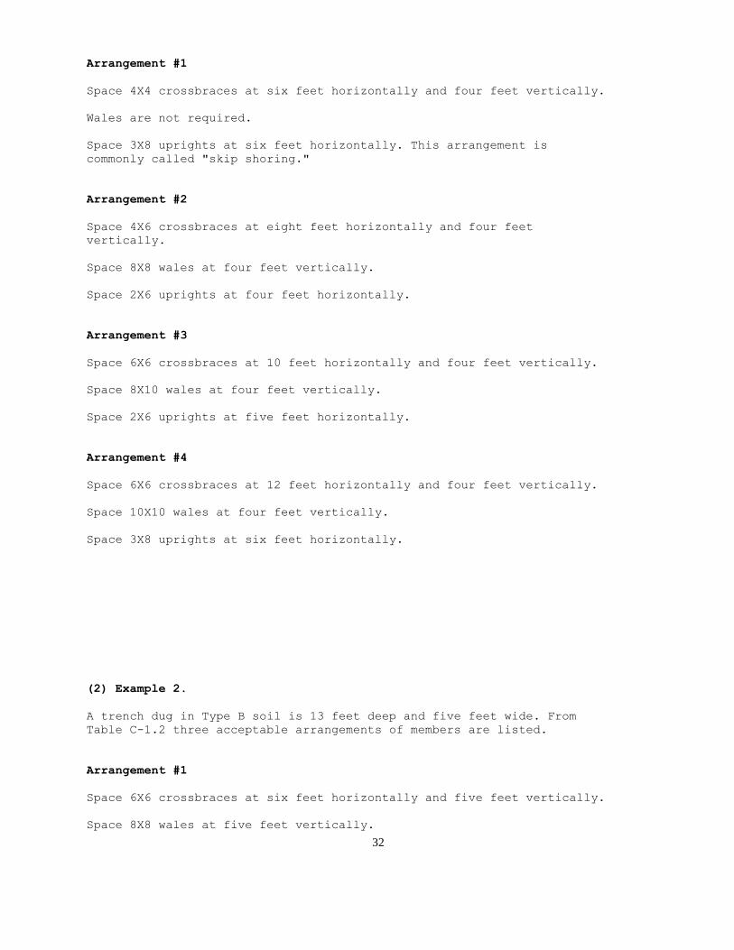
(1) Example 1.
A trench dug in Type A soil is 13 feet deep and five feet wide.
From Table C-1.1, for acceptable arrangements of timber can be used.
32
Arrangement #1
Space 4X4 crossbraces at six feet horizontally and four feet vertically.
Wales are not required.
Space 3X8 uprights at six feet horizontally. This arrangement is
commonly called "skip shoring."
Arrangement #2
Space 4X6 crossbraces at eight feet horizontally and four feet
vertically.
Space 8X8 wales at four feet vertically.
Space 2X6 uprights at four feet horizontally.
Arrangement #3
Space 6X6 crossbraces at 10 feet horizontally and four feet vertically.
Space 8X10 wales at four feet vertically.
Space 2X6 uprights at five feet horizontally.
Arrangement #4
Space 6X6 crossbraces at 12 feet horizontally and four feet vertically.
Space 10X10 wales at four feet vertically.
Space 3X8 uprights at six feet horizontally.
(2) Example 2.
A trench dug in Type B soil is 13 feet deep and five feet wide. From
Table C-1.2 three acceptable arrangements of members are listed.
Arrangement #1
Space 6X6 crossbraces at six feet horizontally and five feet vertically.
Space 8X8 wales at five feet vertically.
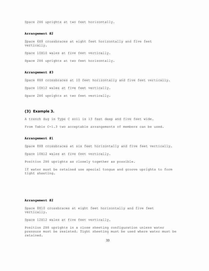
33
Space 2X6 uprights at two feet horizontally.
Arrangement #2
Space 6X8 crossbraces at eight feet horizontally and five feet
vertically.
Space 10X10 wales at five feet vertically.
Space 2X6 uprights at two feet horizontally.
Arrangement #3
Space 8X8 crossbraces at 10 feet horizontally and five feet vertically.
Space 10X12 wales at five feet vertically.
Space 2X6 uprights at two feet vertically.
(3) Example 3.
A trench dug in Type C soil is 13 feet deep and five feet wide.
From Table C-1.3 two acceptable arrangements of members can be used.
Arrangement #1
Space 8X8 crossbraces at six feet horizontally and five feet vertically.
Space 10X12 wales at five feet vertically.
Position 2X6 uprights as closely together as possible.
If water must be retained use special tongue and groove uprights to form
tight sheeting.
Arrangement #2
Space 8X10 crossbraces at eight feet horizontally and five feet
vertically.
Space 12X12 wales at five feet vertically.
Position 2X6 uprights in a close sheeting configuration unless water
pressure must be resisted. Tight sheeting must be used where water must be
retained.

34
(4) Example 4.
A trench dug in Type C soil is 20 feet deep and 11 feet wide. The size and spacing of
members for the section of trench that is over 15 feet in depth is determined using Table C-1.3. Only one arrangement of members is provided.
Space 8X10 crossbraces at six feet horizontally and five feet vertically.
Space 12X12 wales at five feet vertically.
Use 3X6 tight sheeting.
Use of Tables C-2.1 through C-2.3 would follow the same procedures.
(g) Notes for all Tables.
1. Member sizes at spacings other than indicated are to be determined as specified in 1926.652(c), "Design of Protective Systems."
2. When conditions are saturated or submerged use Tight Sheeting. Tight Sheeting
refers to the use of specially-edged timber planks (e.g., tongue and groove) at least
three inches thick, steel sheet piling, or similar construction that when driven or placed
in position provide a tight wall to resist the lateral pressure of water and to prevent the
loss of backfill material. Close Sheeting refers to the placement of planks side-by-side
allowing as little space as possible between them.
3. All spacing indicated is measured center to center.
4. Wales to be installed with greater dimension horizontal.
5. If the vertical distance from the center of the lowest crossbrace to the bottom of the
trench exceeds two and one-half feet, uprights shall be firmly embedded or a mudsill
shall be used. Where uprights are embedded, the vertical distance from the center of the
lowest crossbrace to the bottom of the trench shall not exceed 36 inches. When mudsills
are used, the vertical distance shall not exceed 42 inches. Mudsills are wales that are installed at the tow of the trench side.
6. Trench jacks may be used in lieu of or in combination with timber crossbraces.
7. Placement of crossbraces. When the vertical spacing of crossbraces is four feet, place
the top crossbrace no more than two feet below the top of the trench. When the vertical
spacing of crossbraces is five feet, place the top crossbrace no more than 2.5 feet below
the top of the trench.
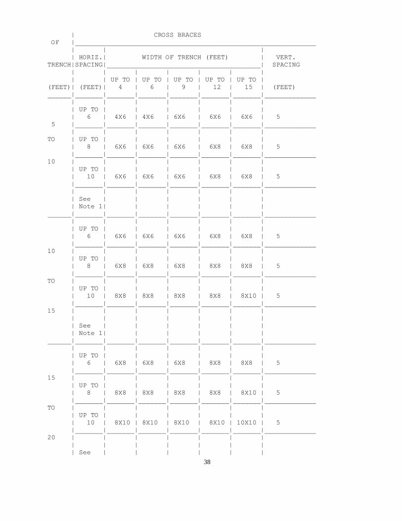
TABLE C-1.1
TIMBER TRENCH SHORING -- MINIMUM TIMBER REQUIREMENTS *

35
SOIL TYPE A P(a) = 25 X H + 72 psf (2 ft Surcharge)
____________________________________________________________________
|
| SIZE (ACTUAL) AND SPACING OF MEMBERS **
|_____________________________________________________________
DEPTH |
| CROSS BRACES
OF |_____________________________________________________________
| | |
| HORIZ.| WIDTH OF TRENCH (FEET) | VERT.
TRENCH|SPACING|_______________________________________| SPACING
| | | | | | |
| | UP TO | UP TO | UP TO | UP TO | UP TO |
(FEET)| (FEET)| 4 | 6 | 9 | 12 | 15 | (FEET)
______|_______|_______|_______|_______|_______|_______|_____________
| | | | | | |
| UP TO | | | | | |
| 6 | 4X4 | 4X4 | 4X6 | 6X6 | 6X6 | 4
5 |_______|_______|_______|_______|_______|_______|_____________
| | | | | | |
TO | UP TO | | | | | |
| 8 | 4X4 | 4X4 | 4X6 | 6X6 | 6X6 | 4
|_______|_______|_______|_______|_______|_______|_____________
10 | | | | | | |
| UP TO | | | | | |
| 10 | 4X6 | 4X6 | 4X6 | 6X6 | 6X6 | 4
|_______|_______|_______|_______|_______|_______|_____________
| | | | | | |
| UP TO | | | | | |
| 12 | 4X6 | 4X6 | 6X6 | 6X6 | 6X6 | 4
______|_______|_______|_______|_______|_______|_______|_____________
| | | | | | |
| UP TO | | | | | |
| 6 | 4X4 | 4X4 | 4X6 | 6X6 | 6X6 | 4
|_______|_______|_______|_______|_______|_______|_____________
10 | | | | | | |
| UP TO | | | | | |
| 8 | 4X6 | 4X6 | 6X6 | 6X6 | 6X6 | 4
|_______|_______|_______|_______|_______|_______|_____________
TO | | | | | | |
| UP TO | | | | | |
| 10 | 6X6 | 6X6 | 6X6 | 6X8 | 6X8 | 4
|_______|_______|_______|_______|_______|_______|_____________
15 | | | | | | |
| UP TO | | | | | |
| 12 | 6X6 | 6X6 | 6X6 | 6X8 | 6X8 | 4
______|_______|_______|_______|_______|_______|_______|_____________
| | | | | | |
| UP TO | | | | | |
| 6 | 6X6 | 6X6 | 6X6 | 6X8 | 6X8 | 4
|_______|_______|_______|_______|_______|_______|_____________
15 | | | | | | |
| UP TO | | | | | |
| 8 | 6X6 | 6X6 | 6X6 | 6X8 | 6X8 | 4
|_______|_______|_______|_______|_______|_______|_____________

36
TO | | | | | | |
| UP TO | | | | | |
| 10 | 8X8 | 8X8 | 8X8 | 8X8 | 8X10 | 4
|_______|_______|_______|_______|_______|_______|_____________
20 | | | | | | |
| UP TO | | | | | |
| 12 | 8X8 | 8X8 | 8X8 | 8X8 | 8X10 | 4
______|_______|_______|_______|_______|_______|_______|_____________
|
OVER | SEE NOTE 1
20 |
______|_____________________________________________________________
TABLE C-1.1
TIMBER TRENCH SHORING -- MINIMUM TIMBER REQUIREMENTS *
SOIL TYPE A P(a) = 25 X H + 72 psf (2 ft Surcharge)
[Continued]
____________________________________________________________________
|
| SIZE (ACTUAL) AND SPACING OF MEMBERS **
|_____________________________________________________________
DEPTH | |
| WALES | UPRIGHTS
OF |_______________|_____________________________________________
| | |
TRENCH| | VERT. | MAXIMUM ALLOWABLE HORIZONTAL SPACING
| |SPACING| (FEET)
| SIZE | |_____________________________________________
| | | | | | |
(FEET)| (IN) |(FEET) | CLOSE | 4 | 5 | 6 | 8
______|_______|_______|_______|_______|_______|_______|_____________
| | | | | | |
| Not | | | | | |
| Req'd | --- | | | | 2X6 |
5 |_______|_______|_______|_______|_______|_______|_____________
| | | | | | |
TO | Not | | | | | |
| Req'd | --- | | | | | 2X8
|_______|_______|_______|_______|_______|_______|_____________
10 | | | | | | |
| | | | | | |
| 8X8 | 4 | | | 2X6 | |
|_______|_______|_______|_______|_______|_______|_____________
| | | | | | |
| | | | | | |
| 8X8 | 4 | | | | 2X6 |
______|_______|_______|_______|_______|_______|_______|_____________
| | | | | | |
| Not | | | | | |
| Req'd | --- | | | | 3X8 |
|_______|_______|_______|_______|_______|_______|_____________
10 | | | | | | |

37
| | | | | | |
| 8X8 | 4 | | 2X6 | | |
|_______|_______|_______|_______|_______|_______|_____________
TO | | | | | | |
| | | | | | |
| 8X10 | 4 | | | 2X6 | |
|_______|_______|_______|_______|_______|_______|_____________
15 | | | | | | |
| | | | | | |
| 10X10 | 4 | | | | 3X8 |
______|_______|_______|_______|_______|_______|_______|_____________
| | | | | | |
| | | | | | |
| 6X8 | 4 | 3X6 | | | |
|_______|_______|_______|_______|_______|_______|_____________
15 | | | | | | |
| | | | | | |
| 8X8 | 4 | 3X6 | | | |
|_______|_______|_______|_______|_______|_______|_____________
TO | | | | | | |
| | | | | | |
| 8X10 | 4 | 3X6 | | | |
|_______|_______|_______|_______|_______|_______|_____________
20 | | | | | | |
| | | | | | |
| 10X10 | 4 | 3X6 | | | |
______|_______|_______|_______|_______|_______|_______|_____________
|
OVER | SEE NOTE 1
20 |
______|_____________________________________________________________
* Mixed oak or equivalent with a bending strength not less than 850
psi.
** Manufactured members of equivalent strength may be substituted for
wood.
TABLE C-1.2
TIMBER TRENCH SHORING -- MINIMUM TIMBER REQUIREMENTS *
SOIL TYPE B P(a) = 45 X H + 72 psf (2 ft Surcharge)
____________________________________________________________________
|
| SIZE (ACTUAL) AND SPACING OF MEMBERS **
|_____________________________________________________________
DEPTH |
38
| CROSS BRACES
OF |_____________________________________________________________
| | |
| HORIZ.| WIDTH OF TRENCH (FEET) | VERT.
TRENCH|SPACING|_______________________________________| SPACING
| | | | | | |
| | UP TO | UP TO | UP TO | UP TO | UP TO |
(FEET)| (FEET)| 4 | 6 | 9 | 12 | 15 | (FEET)
______|_______|_______|_______|_______|_______|_______|_____________
| | | | | | |
| UP TO | | | | | |
| 6 | 4X6 | 4X6 | 6X6 | 6X6 | 6X6 | 5
5 |_______|_______|_______|_______|_______|_______|_____________
| | | | | | |
TO | UP TO | | | | | |
| 8 | 6X6 | 6X6 | 6X6 | 6X8 | 6X8 | 5
|_______|_______|_______|_______|_______|_______|_____________
10 | | | | | | |
| UP TO | | | | | |
| 10 | 6X6 | 6X6 | 6X6 | 6X8 | 6X8 | 5
|_______|_______|_______|_______|_______|_______|_____________
| | | | | | |
| See | | | | | |
| Note 1| | | | | |
______|_______|_______|_______|_______|_______|_______|_____________
| | | | | | |
| UP TO | | | | | |
| 6 | 6X6 | 6X6 | 6X6 | 6X8 | 6X8 | 5
|_______|_______|_______|_______|_______|_______|_____________
10 | | | | | | |
| UP TO | | | | | |
| 8 | 6X8 | 6X8 | 6X8 | 8X8 | 8X8 | 5
|_______|_______|_______|_______|_______|_______|_____________
TO | | | | | | |
| UP TO | | | | | |
| 10 | 8X8 | 8X8 | 8X8 | 8X8 | 8X10 | 5
|_______|_______|_______|_______|_______|_______|_____________
15 | | | | | | |
| | | | | | |
| See | | | | | |
| Note 1| | | | | |
______|_______|_______|_______|_______|_______|_______|_____________
| | | | | | |
| UP TO | | | | | |
| 6 | 6X8 | 6X8 | 6X8 | 8X8 | 8X8 | 5
|_______|_______|_______|_______|_______|_______|_____________
15 | | | | | | |
| UP TO | | | | | |
| 8 | 8X8 | 8X8 | 8X8 | 8X8 | 8X10 | 5
|_______|_______|_______|_______|_______|_______|_____________
TO | | | | | | |
| UP TO | | | | | |
| 10 | 8X10 | 8X10 | 8X10 | 8X10 | 10X10 | 5
|_______|_______|_______|_______|_______|_______|_____________
20 | | | | | | |
| | | | | | |
| See | | | | | |

39
| Note 1| | | | | |
______|_______|_______|_______|_______|_______|_______|_____________
|
OVER | SEE NOTE 1
20 |
______|_____________________________________________________________
TABLE C-1.2
TIMBER TRENCH SHORING -- MINIMUM TIMBER REQUIREMENTS *
SOIL TYPE B P(a) = 45 X H + 72 psf (2 ft Surcharge)
[Continued]
____________________________________________________________________
|
| SIZE (ACTUAL) AND SPACING OF MEMBERS **
|_____________________________________________________________
DEPTH | |
| WALES | UPRIGHTS
OF |_______________|_____________________________________________
| | |
TRENCH| | VERT. | MAXIMUM ALLOWABLE HORIZONTAL SPACING
| |SPACING| (FEET)
| SIZE | |_____________________________________________
| | | | | | |
(FEET)| (IN) |(FEET) | CLOSE | 2 | 3 | |
______|_______|_______|_______|_______|_______|_______|_____________
| | | | | | |
| | | | | | |
| 6X8 | 5 | | | 2X6 | |
5 |_______|_______|_______|_______|_______|_______|_____________
| | | | | | |
TO | | | | | | |
| 8X10 | 5 | | | 2X6 | |
|_______|_______|_______|_______|_______|_______|_____________
10 | | | | | | |
| | | | | | |
| 10X10 | 5 | | | 2X6 | |
|_______|_______|_______|_______|_______|_______|_____________
| | | | | | |
| | | | | | |
| | | | | | |
______|_______|_______|_______|_______|_______|_______|_____________
| | | | | | |
| | | | | | |
| 8X8 | 5 | | 2X6 | | |
|_______|_______|_______|_______|_______|_______|_____________
10 | | | | | | |
| | | | | | |
| 10X10 | 5 | | 2X6 | | |
|_______|_______|_______|_______|_______|_______|_____________
TO | | | | | | |
| | | | | | |
| 10X12 | 5 | | 2X6 | | |

40
|_______|_______|_______|_______|_______|_______|_____________
15 | | | | | | |
| | | | | | |
| | | | | | |
______|_______|_______|_______|_______|_______|_______|_____________
| | | | | | |
| | | | | | |
| 8X10 | 5 | 3X6 | | | |
|_______|_______|_______|_______|_______|_______|_____________
15 | | | | | | |
| | | | | | |
| 10X12 | 5 | 3X6 | | | |
|_______|_______|_______|_______|_______|_______|_____________
TO | | | | | | |
| | | | | | |
| 12X12 | 5 | 3X6 | | | |
|_______|_______|_______|_______|_______|_______|_____________
20 | | | | | | |
| | | | | | |
| | | | | | |
______|_______|_______|_______|_______|_______|_______|_____________
|
OVER | SEE NOTE 1
20 |
______|_____________________________________________________________
* Mixed oak or equivalent with a bending strength not less than 850
psi.
** Manufactured members of equivalent strength may be substituted for
wood.
TABLE C-1.3
TIMBER TRENCH SHORING -- MINIMUM TIMBER REQUIREMENTS *
SOIL TYPE C P(a) = 80 X H + 72 psf (2 ft Surcharge)
____________________________________________________________________
|
| SIZE (ACTUAL) AND SPACING OF MEMBERS **
|_____________________________________________________________
DEPTH |

41
| CROSS BRACES
OF |_____________________________________________________________
| | |
| HORIZ.| WIDTH OF TRENCH (FEET) | VERT.
TRENCH|SPACING|_______________________________________| SPACING
| | | | | | |
| | UP TO | UP TO | UP TO | UP TO | UP TO |
(FEET)| (FEET)| 4 | 6 | 9 | 12 | 15 | (FEET)
______|_______|_______|_______|_______|_______|_______|_____________
| | | | | | |
| UP TO | | | | | |
| 6 | 6X8 | 6X8 | 6X8 | 8X8 | 8X8 | 5
5 |_______|_______|_______|_______|_______|_______|_____________
| | | | | | |
TO | UP TO | | | | | |
| 8 | 8X8 | 8X8 | 8X8 | 8X8 | 8X10 | 5
|_______|_______|_______|_______|_______|_______|_____________
10 | | | | | | |
| UP TO | | | | | |
| 10 | 8X10 | 8X10 | 8X10 | 8X10 | 10X10 | 5
|_______|_______|_______|_______|_______|_______|_____________
| | | | | | |
| See | | | | | |
| Note 1| | | | | |
______|_______|_______|_______|_______|_______|_______|_____________
| | | | | | |
| UP TO | | | | | |
| 6 | 8X8 | 8X8 | 8X8 | 8X8 | 8X10 | 5
|_______|_______|_______|_______|_______|_______|_____________
10 | | | | | | |
| UP TO | | | | | |
| 8 | 8X10 | 8X10 | 8X10 | 8X10 | 10X10 | 5
|_______|_______|_______|_______|_______|_______|_____________
TO | | | | | | |
| See | | | | | |
| Note 1| | | | | |
|_______|_______|_______|_______|_______|_______|_____________
15 | | | | | | |
| See | | | | | |
| Note 1| | | | | |
______|_______|_______|_______|_______|_______|_______|_____________
| | | | | | |
| UP TO | | | | | |
| 6 | 8X10 | 8X10 | 8X10 | 8X10 | 10X10 | 5
|_______|_______|_______|_______|_______|_______|_____________
15 | | | | | | |
| See | | | | | |
| Note 1| | | | | |
|_______|_______|_______|_______|_______|_______|_____________
TO | | | | | | |
| See | | | | | |
| Note 1| | | | | |
|_______|_______|_______|_______|_______|_______|_____________
20 | | | | | | |
| See | | | | | |
| Note 1| | | | | |
______|_______|_______|_______|_______|_______|_______|_____________

42
|
OVER | SEE NOTE 1
20 |
______|_____________________________________________________________
TABLE C-1.3
TIMBER TRENCH SHORING -- MINIMUM TIMBER REQUIREMENTS *
SOIL TYPE C P(a) = 80 X H + 72 psf (2 ft Surcharge)
[Continued]
____________________________________________________________________
|
| SIZE (ACTUAL) AND SPACING OF MEMBERS **
|_____________________________________________________________
DEPTH | |
| WALES | UPRIGHTS
OF |_______________|_____________________________________________
| | |
TRENCH| | VERT. | MAXIMUM ALLOWABLE HORIZONTAL SPACING
| |SPACING| (FEET)
| SIZE | |_____________________________________________
| | | | | | |
(FEET)| (IN) |(FEET) | CLOSE | | | |
______|_______|_______|_______|_______|_______|_______|_____________
| | | | | | |
| | | | | | |
| 8X10 | 5 | 2X6 | | | |
5 |_______|_______|_______|_______|_______|_______|_____________
| | | | | | |
TO | | | | | | |
| 10X12 | 5 | 2X6 | | | |
|_______|_______|_______|_______|_______|_______|_____________
10 | | | | | | |
| | | | | | |
| 12X12 | 5 | 2X6 | | | |
|_______|_______|_______|_______|_______|_______|_____________
| | | | | | |
| | | | | | |
| | | | | | |
______|_______|_______|_______|_______|_______|_______|_____________
| | | | | | |
| | | | | | |
| 10X12 | 5 | 2X6 | | | |
|_______|_______|_______|_______|_______|_______|_____________
10 | | | | | | |
| | | | | | |
| 12X12 | 5 | 2X6 | | | |
|_______|_______|_______|_______|_______|_______|_____________
TO | | | | | | |
| | | | | | |
| | | | | | |
|_______|_______|_______|_______|_______|_______|_____________
15 | | | | | | |

43
| | | | | | |
| | | | | | |
______|_______|_______|_______|_______|_______|_______|_____________
| | | | | | |
| | | | | | |
| 12X12 | 5 | 3X6 | | | |
|_______|_______|_______|_______|_______|_______|_____________
15 | | | | | | |
| | | | | | |
| | | | | | |
|_______|_______|_______|_______|_______|_______|_____________
TO | | | | | | |
| | | | | | |
| | | | | | |
|_______|_______|_______|_______|_______|_______|_____________
20 | | | | | | |
| | | | | | |
| | | | | | |
______|_______|_______|_______|_______|_______|_______|_____________
|
OVER | SEE NOTE 1
20 |
______|_____________________________________________________________
* Mixed oak or equivalent with a bending strength not less than 850
psi.
** Manufactured members of equivalent strength may be substituted for
wood.
TABLE C-2.1
TIMBER TRENCH SHORING -- MINIMUM TIMBER REQUIREMENTS *
SOIL TYPE A P(a) = 25 X H + 72 psf (2 ft Surcharge)
____________________________________________________________________
|
| SIZE (S4S) AND SPACING OF MEMBERS **
|_____________________________________________________________

44
DEPTH |
| CROSS BRACES
OF |_____________________________________________________________
| | |
| HORIZ.| WIDTH OF TRENCH (FEET) | VERT.
TRENCH|SPACING|_______________________________________| SPACING
| | | | | | |
| | UP TO | UP TO | UP TO | UP TO | UP TO |
(FEET)| (FEET)| 4 | 6 | 9 | 12 | 15 | (FEET)
______|_______|_______|_______|_______|_______|_______|_____________
| | | | | | |
| UP TO | | | | | |
| 6 | 4X4 | 4X4 | 4X4 | 4X4 | 4X6 | 4
5 |_______|_______|_______|_______|_______|_______|_____________
| | | | | | |
TO | UP TO | | | | | |
| 8 | 4X4 | 4X4 | 4X4 | 4X6 | 4X6 | 4
|_______|_______|_______|_______|_______|_______|_____________
10 | | | | | | |
| UP TO | | | | | |
| 10 | 4X6 | 4X6 | 4X6 | 6X6 | 6X6 | 4
|_______|_______|_______|_______|_______|_______|_____________
| | | | | | |
| UP TO | | | | | |
| 12 | 4X6 | 4X6 | 4X6 | 6X6 | 6X6 | 4
______|_______|_______|_______|_______|_______|_______|_____________
| | | | | | |
| UP TO | | | | | |
| 6 | 4X4 | 4X4 | 4X4 | 6X6 | 6X6 | 4
|_______|_______|_______|_______|_______|_______|_____________
10 | | | | | | |
| UP TO | | | | | |
| 8 | 4X6 | 4X6 | 4X6 | 6X6 | 6X6 | 4
|_______|_______|_______|_______|_______|_______|_____________
TO | | | | | | |
| UP TO | | | | | |
| 10 | 6X6 | 6X6 | 6X6 | 6X6 | 6X6 | 4
|_______|_______|_______|_______|_______|_______|_____________
15 | | | | | | |
| UP TO | | | | | |
| 12 | 6X6 | 6X6 | 6X6 | 6X6 | 6X6 | 4
______|_______|_______|_______|_______|_______|_______|_____________
| | | | | | |
| UP TO | | | | | |
| 6 | 6X6 | 6X6 | 6X6 | 6X6 | 6X6 | 4
|_______|_______|_______|_______|_______|_______|_____________
15 | | | | | | |
| UP TO | | | | | |
| 8 | 6X6 | 6X6 | 6X6 | 6X6 | 6X6 | 4
|_______|_______|_______|_______|_______|_______|_____________
TO | | | | | | |
| UP TO | | | | | |
| 10 | 6X6 | 6X6 | 6X6 | 6X6 | 6X8 | 4
|_______|_______|_______|_______|_______|_______|_____________
20 | | | | | | |
| UP TO | | | | | |
| 12 | 6X6 | 6X6 | 6X6 | 6X8 | 6X8 | 4

45
______|_______|_______|_______|_______|_______|_______|_____________
|
OVER | SEE NOTE 1
20 |
______|_____________________________________________________________
TABLE C-2.1
TIMBER TRENCH SHORING -- MINIMUM TIMBER REQUIREMENTS *
SOIL TYPE A P(a) = 25 X H + 72 psf (2 ft Surcharge)
[Continued]
____________________________________________________________________
|
| SIZE (S4S) AND SPACING OF MEMBERS **
|_____________________________________________________________
DEPTH | |
| WALES | UPRIGHTS
OF |_______________|_____________________________________________
| | |
TRENCH| | VERT. | MAXIMUM ALLOWABLE HORIZONTAL SPACING
| |SPACING| (FEET)
| SIZE | |_____________________________________________
| | | | | | |
(FEET)| (IN) |(FEET) | CLOSE | 4 | 5 | 6 | 8
______|_______|_______|_______|_______|_______|_______|_____________
| | | | | | |
| Not | Not | | | | |
| Req'd | Req'd | | | | 4X6 |
5 |_______|_______|_______|_______|_______|_______|_____________
| | | | | | |
TO | Not | Not | | | | |
| Req'd | Req'd | | | | | 4X8
|_______|_______|_______|_______|_______|_______|_____________
10 | | | | | | |
| | | | | | |
| 8X8 | 4 | | | 4X6 | |
|_______|_______|_______|_______|_______|_______|_____________
| | | | | | |
| | | | | | |
| 8X8 | 4 | | | | 4X6 |
______|_______|_______|_______|_______|_______|_______|_____________
| | | | | | |
| Not | Not | | | | |
| Req'd | Req'd | | | | 4X10 |
|_______|_______|_______|_______|_______|_______|_____________
10 | | | | | | |
| | | | | | |
| 6X8 | 4 | | 4X6 | | |
|_______|_______|_______|_______|_______|_______|_____________
TO | | | | | | |
| | | | | | |
| 8X8 | 4 | | | 4X8 | |
|_______|_______|_______|_______|_______|_______|_____________

46
15 | | | | | | |
| | | | | | |
| 8X10 | 4 | | 4X6 | | 4X10 |
______|_______|_______|_______|_______|_______|_______|_____________
| | | | | | |
| | | | | | |
| 6X8 | 4 | 3X6 | | | |
|_______|_______|_______|_______|_______|_______|_____________
15 | | | | | | |
| | | | | | |
| 8X8 | 4 | 3X6 | 4x12 | | |
|_______|_______|_______|_______|_______|_______|_____________
TO | | | | | | |
| | | | | | |
| 8X10 | 4 | 3X6 | | | |
|_______|_______|_______|_______|_______|_______|_____________
20 | | | | | | |
| | | | | | |
| 8X12 | 4 | 3X6 | 4x12 | | |
______|_______|_______|_______|_______|_______|_______|_____________
|
OVER | SEE NOTE 1
20 |
______|_____________________________________________________________
* Douglas fir or equivalent with a bending strength not less than
1500 psi.
** Manufactured members of equivalent strength may be substituted for
wood.
TABLE C-2.2
TIMBER TRENCH SHORING -- MINIMUM TIMBER REQUIREMENTS *
SOIL TYPE B P(a) = 45 X H + 72 psf (2 ft Surcharge)
____________________________________________________________________
|
| SIZE (S4S) AND SPACING OF MEMBERS **
|_____________________________________________________________
DEPTH |

47
| CROSS BRACES
OF |_____________________________________________________________
| | |
| HORIZ.| WIDTH OF TRENCH (FEET) | VERT.
TRENCH|SPACING|_______________________________________| SPACING
| | | | | | |
| | UP TO | UP TO | UP TO | UP TO | UP TO |
(FEET)| (FEET)| 4 | 6 | 9 | 12 | 15 | (FEET)
______|_______|_______|_______|_______|_______|_______|_____________
| | | | | | |
| UP TO | | | | | |
| 6 | 4X6 | 4X6 | 4X6 | 6X6 | 6X6 | 5
5 |_______|_______|_______|_______|_______|_______|_____________
| | | | | | |
TO | UP TO | | | | | |
| 8 | 4X6 | 4X6 | 6X6 | 6X6 | 6X6 | 5
|_______|_______|_______|_______|_______|_______|_____________
10 | | | | | | |
| UP TO | | | | | |
| 10 | 4X6 | 4X6 | 6X6 | 6X6 | 6X8 | 5
|_______|_______|_______|_______|_______|_______|_____________
| | | | | | |
| See | | | | | |
| Note 1| | | | | |
______|_______|_______|_______|_______|_______|_______|_____________
| | | | | | |
| UP TO | | | | | |
| 6 | 6X6 | 6X6 | 6X6 | 6X8 | 6X8 | 5
|_______|_______|_______|_______|_______|_______|_____________
10 | | | | | | |
| UP TO | | | | | |
| 8 | 6X8 | 6X8 | 6X8 | 8X8 | 8X8 | 5
|_______|_______|_______|_______|_______|_______|_____________
TO | | | | | | |
| UP TO | | | | | |
| 10 | 6X8 | 6X8 | 8X8 | 8X8 | 8X8 | 5
|_______|_______|_______|_______|_______|_______|_____________
15 | | | | | | |
| | | | | | |
| See | | | | | |
| Note 1| | | | | |
______|_______|_______|_______|_______|_______|_______|_____________
| | | | | | |
| UP TO | | | | | |
| 6 | 6X8 | 6X8 | 6X8 | 6X8 | 8X8 | 5
|_______|_______|_______|_______|_______|_______|_____________
15 | | | | | | |
| UP TO | | | | | |
| 8 | 6X8 | 6X8 | 6X8 | 8X8 | 8X8 | 5
|_______|_______|_______|_______|_______|_______|_____________
TO | | | | | | |
| UP TO | | | | | |
| 10 | 8X8 | 8X8 | 8X8 | 8X8 | 8X8 | 5
|_______|_______|_______|_______|_______|_______|_____________
20 | | | | | | |
| | | | | | |
| See | | | | | |
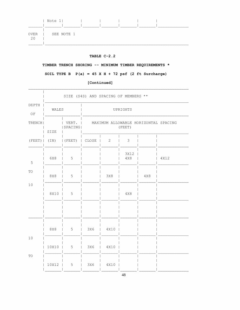
48
| Note 1| | | | | |
______|_______|_______|_______|_______|_______|_______|_____________
|
OVER | SEE NOTE 1
20 |
______|_____________________________________________________________
TABLE C-2.2
TIMBER TRENCH SHORING -- MINIMUM TIMBER REQUIREMENTS *
SOIL TYPE B P(a) = 45 X H + 72 psf (2 ft Surcharge)
[Continued]
____________________________________________________________________
|
| SIZE (S4S) AND SPACING OF MEMBERS **
|_____________________________________________________________
DEPTH | |
| WALES | UPRIGHTS
OF |_______________|_____________________________________________
| | |
TRENCH| | VERT. | MAXIMUM ALLOWABLE HORIZONTAL SPACING
| |SPACING| (FEET)
| SIZE | |_____________________________________________
| | | | | | |
(FEET)| (IN) |(FEET) | CLOSE | 2 | 3 | |
______|_______|_______|_______|_______|_______|_______|_____________
| | | | | | |
| | | | | 3X12 | |
| 6X8 | 5 | | | 4X8 | | 4X12
5 |_______|_______|_______|_______|_______|_______|_____________
| | | | | | |
TO | | | | | | |
| 8X8 | 5 | | 3X8 | | 4X8 |
|_______|_______|_______|_______|_______|_______|_____________
10 | | | | | | |
| | | | | | |
| 8X10 | 5 | | | 4X8 | |
|_______|_______|_______|_______|_______|_______|_____________
| | | | | | |
| | | | | | |
| | | | | | |
______|_______|_______|_______|_______|_______|_______|_____________
| | | | | | |
| | | | | | |
| 8X8 | 5 | 3X6 | 4X10 | | |
|_______|_______|_______|_______|_______|_______|_____________
10 | | | | | | |
| | | | | | |
| 10X10 | 5 | 3X6 | 4X10 | | |
|_______|_______|_______|_______|_______|_______|_____________
TO | | | | | | |
| | | | | | |
| 10X12 | 5 | 3X6 | 4X10 | | |
|_______|_______|_______|_______|_______|_______|_____________

49
15 | | | | | | |
| | | | | | |
| | | | | | |
______|_______|_______|_______|_______|_______|_______|_____________
| | | | | | |
| | | | | | |
| 8X10 | 5 | 4X6 | | | |
|_______|_______|_______|_______|_______|_______|_____________
15 | | | | | | |
| | | | | | |
| 10X12 | 5 | 4X6 | | | |
|_______|_______|_______|_______|_______|_______|_____________
TO | | | | | | |
| | | | | | |
| 12X12 | 5 | 4X6 | | | |
|_______|_______|_______|_______|_______|_______|_____________
20 | | | | | | |
| | | | | | |
| | | | | | |
______|_______|_______|_______|_______|_______|_______|_____________
|
OVER | SEE NOTE 1
20 |
______|_____________________________________________________________
* Douglas fir or equivalent with a bending strength not less than
1500 psi.
** Manufactured members of equivalent strength may be substituted for
wood.
TABLE C-2.3
TIMBER TRENCH SHORING -- MINIMUM TIMBER REQUIREMENTS *
SOIL TYPE C P(a) = 80 X H + 72 psf (2 ft Surcharge)
____________________________________________________________________
|
| SIZE (S4S) AND SPACING OF MEMBERS **
|_____________________________________________________________
DEPTH |

50
| CROSS BRACES
OF |_____________________________________________________________
| | |
| HORIZ.| WIDTH OF TRENCH (FEET) | VERT.
TRENCH|SPACING|_______________________________________| SPACING
| | | | | | |
| | UP TO | UP TO | UP TO | UP TO | UP TO |
(FEET)| (FEET)| 4 | 6 | 9 | 12 | 15 | (FEET)
______|_______|_______|_______|_______|_______|_______|_____________
| | | | | | |
| UP TO | | | | | |
| 6 | 6X6 | 6X6 | 6X6 | 6X6 | 8X8 | 5
5 |_______|_______|_______|_______|_______|_______|_____________
| | | | | | |
TO | UP TO | | | | | |
| 8 | 6X6 | 6X6 | 6X6 | 8X8 | 8X8 | 5
|_______|_______|_______|_______|_______|_______|_____________
10 | | | | | | |
| UP TO | | | | | |
| 10 | 6X6 | 6X6 | 8X8 | 8X8 | 8X8 | 5
|_______|_______|_______|_______|_______|_______|_____________
| | | | | | |
| See | | | | | |
| Note 1| | | | | |
______|_______|_______|_______|_______|_______|_______|_____________
| | | | | | |
| UP TO | | | | | |
| 6 | 6X8 | 6X8 | 6X8 | 8X8 | 8X8 | 5
|_______|_______|_______|_______|_______|_______|_____________
10 | | | | | | |
| UP TO | | | | | |
| 8 | 8X8 | 8X8 | 8X8 | 8X8 | 8X8 | 5
|_______|_______|_______|_______|_______|_______|_____________
TO | | | | | | |
| See | | | | | |
| Note 1| | | | | |
|_______|_______|_______|_______|_______|_______|_____________
15 | | | | | | |
| See | | | | | |
| Note 1| | | | | |
______|_______|_______|_______|_______|_______|_______|_____________
| | | | | | |
| UP TO | | | | | |
| 6 | 8X8 | 8X8 | 8X8 | 8X10 | 8X10 | 5
|_______|_______|_______|_______|_______|_______|_____________
15 | | | | | | |
| See | | | | | |
| Note 1| | | | | |
|_______|_______|_______|_______|_______|_______|_____________
TO | | | | | | |
| See | | | | | |
| Note 1| | | | | |
|_______|_______|_______|_______|_______|_______|_____________
20 | | | | | | |
| See | | | | | |
| Note 1| | | | | |
______|_______|_______|_______|_______|_______|_______|_____________

51
|
OVER | SEE NOTE 1
20 |
______|_____________________________________________________________
TABLE C-2.3
TIMBER TRENCH SHORING -- MINIMUM TIMBER REQUIREMENTS *
SOIL TYPE C P(a) = 80 X H + 72 psf (2 ft Surcharge)
[Continued]
____________________________________________________________________
|
| SIZE (S4S) AND SPACING OF MEMBERS **
|_____________________________________________________________
DEPTH | |
| WALES | UPRIGHTS
OF |_______________|_____________________________________________
| | |
TRENCH| | VERT. | MAXIMUM ALLOWABLE HORIZONTAL SPACING
| |SPACING| (FEET)
| SIZE | |_____________________________________________
| | | | | | |
(FEET)| (IN) |(FEET) | CLOSE | | | |
______|_______|_______|_______|_______|_______|_______|_____________
| | | | | | |
| | | | | | |
| 8X8 | 5 | 3X6 | | | |
5 |_______|_______|_______|_______|_______|_______|_____________
| | | | | | |
TO | | | | | | |
| 10X10 | 5 | 3X6 | | | |
|_______|_______|_______|_______|_______|_______|_____________
10 | | | | | | |
| | | | | | |
| 10X12 | 5 | 3X6 | | | |
|_______|_______|_______|_______|_______|_______|_____________
| | | | | | |
| | | | | | |
| | | | | | |
______|_______|_______|_______|_______|_______|_______|_____________
| | | | | | |
| | | | | | |
| 10X10 | 5 | 4X6 | | | |
|_______|_______|_______|_______|_______|_______|_____________
10 | | | | | | |
| | | | | | |
| 12X12 | 5 | 4X6 | | | |
|_______|_______|_______|_______|_______|_______|_____________
TO | | | | | | |
| | | | | | |
| | | | | | |
|_______|_______|_______|_______|_______|_______|_____________
15 | | | | | | |

52
| | | | | | |
| | | | | | |
______|_______|_______|_______|_______|_______|_______|_____________
| | | | | | |
| | | | | | |
| 10X12 | 5 | 4X6 | | | |
|_______|_______|_______|_______|_______|_______|_____________
15 | | | | | | |
| | | | | | |
| | | | | | |
|_______|_______|_______|_______|_______|_______|_____________
TO | | | | | | |
| | | | | | |
| | | | | | |
|_______|_______|_______|_______|_______|_______|_____________
20 | | | | | | |
| | | | | | |
| | | | | | |
______|_______|_______|_______|_______|_______|_______|_____________
|
OVER | SEE NOTE 1
20 |
______|_____________________________________________________________
* Douglas fir or equivalent with a bending strength not less than
1500 psi.
** Manufactured members of equivalent strength may be substituted for
wood.

53
APPENDIX D
Aluminum Hydraulic Shoring for Trenches

54
(a) Scope. This appendix contains information that can be used when aluminum
hydraulic shoring is provided as a method of protection against cave-ins in trenches that
do not exceed 20 feet (6.1m) in depth. This appendix must be used when design of the
aluminum hydraulic protective system cannot be performed in accordance with 1926.652(c)(2).
(b) Soil Classification. In order to use data presented in this appendix, the soil type or
types in which the excavation is made must first be determined using the soil classification method set forth in appendix A of subpart P of part 1926.
(c) Presentation of Information. Information is presented in several forms as follows:
(1) Information is presented in tabular form in Tables D-1.1, D-1.2, D-1.3 and D-1.4.
Each table presents the maximum vertical and horizontal spacings that may be used
with various aluminum member sizes and various hydraulic cylinder sizes. Each table
contains data only for the particular soil type in which the excavation or portion of the
excavation is made. Tables D-1.1 and D-1.2 are for vertical shores in Types A and B soil.
Tables D-1.3 and D-1.4 are for horizontal waler systems in Types B and C soil.
(2) Information concerning the basis of the tabular data and the limitations of the data is presented in paragraph (d) of this appendix.
(3) Information explaining the use of the tabular data is presented in paragraph (e) of this appendix.
(4) Information illustrating the use of the tabular data is presented in paragraph (f) of this appendix.
(5) Miscellaneous notations (Footnotes) regarding Table D-1.1 through D-1.4 are
presented in paragraph (g) of this appendix.
(6) Figures, illustrating typical installations of hydraulic shoring, are included just prior
to the Tables. The illustrations page is entitled "Aluminum Hydraulic Shoring: Typical Installations."
(d) Basis and limitations of the data.
(1) Vertical shore rails and horizontal wales are those that meet the Section Modulus
requirements in the D-1 Tables. Aluminum material is 6061-T6 or material of equivalent
strength and properties.
(2) Hydraulic cylinders specifications. (i) 2-inch cylinders shall be a minimum 2-inch
inside diameter with a minimum safe working capacity of no less than 18,000 pounds
axial compressive load at maximum extension. Maximum extension is to include full range of cylinder extensions as recommended by product manufacturer.
(ii) 3-inch cylinders shall be a minimum 3-inch inside diameter with a safe working
capacity of not less than 30,000 pounds axial compressive load at extensions as

55
recommended by product manufacturer.
(3) Limitation of application.
(i) It is not intended that the aluminum hydraulic specification apply to every situation
that may be experienced in the field. These data were developed to apply to the
situations that are most commonly experienced in current trenching practice. Shoring
systems for use in situations that are not covered by the data in this appendix must be otherwise designed as specified in 1926.652(c).
(ii) When any of the following conditions are present, the members specified in the
Tables are not considered adequate. In this case, an alternative aluminum hydraulic
shoring system or other type of protective system must be designed in accordance with
1926.652.
(A) When vertical loads imposed on cross braces exceed a 100 Pound gravity load distributed on a one foot section of the center of the hydraulic cylinder.
(B) When surcharge loads are present from equipment weighing in excess of 20,000 pounds.
(C) When only the lower portion of a trench is shored and the remaining portion of the
trench is sloped or benched unless: The sloped portion is sloped at an angle less steep
than three horizontal to one vertical; or the members are selected from the tables for
use at a depth which is determined from the top of the overall trench, and not from the toe of the sloped portion.
(e) Use of Tables D-1.1, D-1.2, D-1.3 and D-1.4. The members of the shoring system
that are to be selected using this information are the hydraulic cylinders, and either the
vertical shores or the horizontal wales. When a waler system is used the vertical timber
sheeting to be used is also selected from these tables. The Tables D-1.1 and D-1.2 for
vertical shores are used in Type A and B soils that do not require sheeting. Type B soils
that may require sheeting, and Type C soils that always require sheeting, are found in
the horizontal wale Tables D-1.3 and D-1.4. The soil type must first be determined in
accordance with the soil classification system described in appendix A to subpart P of
part 1926. Using the appropriate table, the selection of the size and spacing of the
members is made. The selection is based on the depth and width of the trench where
the members are to be installed. In these tables the vertical spacing is held constant at
four feet on center. The tables show the maximum horizontal spacing of cylinders
allowed for each size of wale in the waler system tables, and in the vertical shore tables,
the hydraulic cylinder horizontal spacing is the same as the vertical shore spacing.
(f) Example to Illustrate the Use of the Tables:
(1) Example 1:
A trench dug in Type A soil is 6 feet deep and 3 feet wide. From Table D-1.1: Find
vertical shores and 2 inch diameter cylinders spaced 8 feet on center (o.c.) horizontally

56
and 4 feet on center (o.c.) vertically. (See Figures 1 & 3 for typical installations.)
(2) Example 2:
A trench is dug in Type B soil that does not require sheeting, 13 feet deep and 5 feet
wide. From Table D-1.2: Find vertical shores and 2 inch diameter cylinders spaced 6.5
feet o.c. horizontally and 4 feet o.c. vertically. (See Figures 1 & 3 for typical
installations.)
(3) A trench is dug in Type B soil that does not require sheeting, but does experience
some minor raveling of the trench face. the trench is 16 feet deep and 9 feet wide. From
Table D-1.2: Find vertical shores and 2 inch diameter cylinder (with special oversleeves
as designated by Footnote #2) spaced 5.5 feet o.c. horizontally and 4 feet o.c.
vertically. Plywood (per Footnote (g)(7) to the D-1 Table) should be used behind the shores. (See Figures 2 & 3 for typical installations.)
(4) Example 4: A trench is dug in previously disturbed Type B soil, with characteristics of
a Type C soil, and will require sheeting. The trench is 18 feet deep, and 12 feet wide 8
foot horizontal spacing between cylinders is desired for working space. From Table D-
1.3: Find horizontal wale with a section modulus of 14.0 spaced at 4 feet o.c. vertically
and 3 inch diameter cylinder spaced at 9 feet maximum o.c. horizontally, 3 x 12 timber sheeting is required at close spacing vertically. (See Figure 4 for typical installation.)
(5) Example 5: A trench is dug in Type C soil, 9 feet deep and 4 feet wide. Horizontal
cylinder spacing in excess of 6 feet is desired for working space. From Table D-1.4: Find
horizontal wale with a section modulus of 7.0 and 2 inch diameter cylinders spaced at
6.5 feet o.c. horizontally. Or, find horizontal wale with a 14.0 section modulus and 3 inch
diameter cylinder spaced at 10 feet o.c. horizontally. Both wales are spaced 4 feet o.c.
vertically, 3 x 12 timber sheeting is required at close spacing vertically. (See Figure 4 for typical installation.)
(g) Footnotes, and general notes, for Tables D-1.1, D-1.2, D-1.3, and D-1.4.
(1) For applications other than those listed in the tables, refer to 1926.652(c)(2) for use
of manufacturer's tabulated data. For trench depths in excess of 20 feet, refer to 1926.652(c)(2) and 1926.652(c)(3).
(2) 2 inch diameter cylinders, at this width, shall have structural steel tube (3.5 x 3.5 x
0.1875) oversleeves, or structural oversleeves of manufacturer's specification, extending
the full, collapsed length.
(3) Hydraulic cylinders capacities. (i) 2-inch cylinders shall be a minimum 2-inch inside
diameter with a safe working capacity of not less than 18,000 pounds axial compressive
load at maximum extension. Maximum extension is to include full range of cylinder extensions as recommended by product manufacturer.
(ii) 3-inch cylinders shall be a minimum 3-inch inside diameter with a safe work capacity

57
of not less than 30,000 pounds axial compressive load at maximum extension. Maximum
extension is to include full range of cylinder extensions as recommended by product manufacturer.
(4) All spacing indicated is measured center to center.
(5) Vertical shoring rails shall have a minimum section modulus of 0.40 inch.
(6) When vertical shores are used, there must be a minimum of three shores spaced equally, horizontally, in a group.
(7) Plywood shall be 1.125 inch thick softwood or 0.75 inch thick, 14 ply, arctic white
birch (Finland form). Please note that plywood is not intended as a structural member, but only for prevention of local raveling (sloughing of the trench face) between shores.
(8) See appendix C for timber specifications.
(9) Wales are calculated for simple span conditions.
(10) See appendix D, item (d), for basis and limitations of the data.
ALUMINUM HYDRAULIC SHORING
TYPICAL INSTALLATIONS
Figure No. 1 - Vertical aluminum hydraulic shoring (spot bracing)
(For Figure No. 1, Click Here)
Figure No. 2 - Vertical aluminum hydraulic shoring (with plywood)
(For Figure No. 2, Click Here)
Figure No. 3 - Vertical aluminum hydraulic shoring (stacked)
(For Figure No. 3, Click Here)
Figure No. 4 - Aluminum hydraulic shoring - Waler System (typical)
(For Figure No. 4, Click Here)
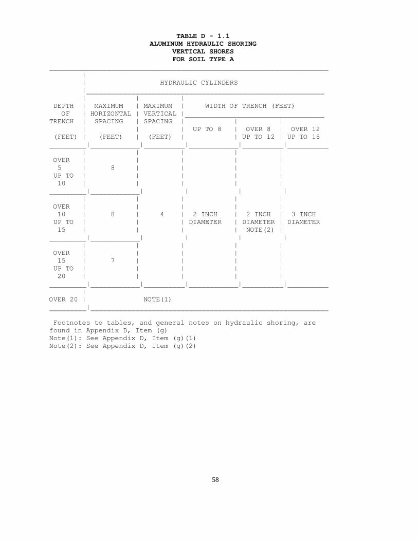
58
TABLE D - 1.1
ALUMINUM HYDRAULIC SHORING
VERTICAL SHORES
FOR SOIL TYPE A
____________________________________________________________________
|
| HYDRAULIC CYLINDERS
|__________________________________________________________
| | |
DEPTH | MAXIMUM | MAXIMUM | WIDTH OF TRENCH (FEET)
OF | HORIZONTAL | VERTICAL |__________________________________
TRENCH | SPACING | SPACING | | |
| | | UP TO 8 | OVER 8 | OVER 12
(FEET) | (FEET) | (FEET) | | UP TO 12 | UP TO 15
_________|____________|__________|____________|__________|__________
| | | | |
OVER | | | | |
5 | 8 | | | |
UP TO | | | | |
10 | | | | |
_________|____________| | | |
| | | | |
OVER | | | | |
10 | 8 | 4 | 2 INCH | 2 INCH | 3 INCH
UP TO | | | DIAMETER | DIAMETER | DIAMETER
15 | | | | NOTE(2) |
_________|____________| | | |
| | | | |
OVER | | | | |
15 | 7 | | | |
UP TO | | | | |
20 | | | | |
_________|____________|__________|____________|__________|__________
|
OVER 20 | NOTE(1)
_________|__________________________________________________________
Footnotes to tables, and general notes on hydraulic shoring, are
found in Appendix D, Item (g)
Note(1): See Appendix D, Item (g)(1)
Note(2): See Appendix D, Item (g)(2)

59
TABLE D - 1.2
ALUMINUM HYDRAULIC SHORING
VERTICAL SHORES
FOR SOIL TYPE B
____________________________________________________________________
|
| HYDRAULIC CYLINDERS
|__________________________________________________________
| | |
DEPTH | MAXIMUM | MAXIMUM | WIDTH OF TRENCH (FEET)
OF | HORIZONTAL | VERTICAL |__________________________________
TRENCH | SPACING | SPACING | | |
| | | UP TO 8 | OVER 8 | OVER 12
(FEET) | (FEET) | (FEET) | | UP TO 12 | UP TO 15
_________|____________|__________|____________|__________|__________
| | | | |
OVER | | | | |
5 | 8 | | | |
UP TO | | | | |
10 | | | | |
_________|____________| | | |
| | | | |
OVER | | | | |
10 | 6.5 | 4 | 2 INCH | 2 INCH | 3 INCH
UP TO | | | DIAMETER | DIAMETER | DIAMETER
15 | | | | NOTE(2) |
_________|____________| | | |
| | | | |
OVER | | | | |
15 | 5.5 | | | |
UP TO | | | | |
20 | | | | |
_________|____________|__________|____________|__________|__________
|
OVER 20 | NOTE(1)
_________|__________________________________________________________
Footnotes to tables, and general notes on hydraulic shoring, are
found in Appendix D, Item (g)
Note(1): See Appendix D, Item (g)(1)
Note(2): See Appendix D, Item (g)(2)
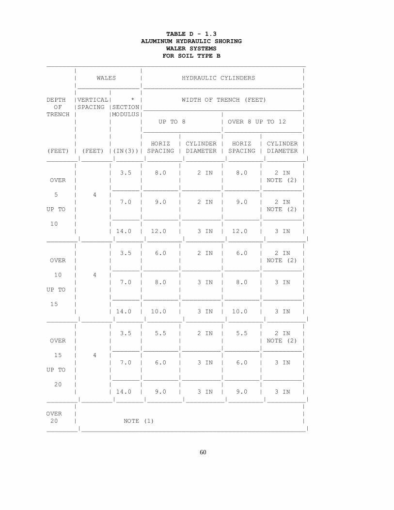
60
TABLE D - 1.3
ALUMINUM HYDRAULIC SHORING
WALER SYSTEMS
FOR SOIL TYPE B
___________________________________________________________________
| | |
| WALES | HYDRAULIC CYLINDERS |
|________________|_________________________________________|
| | | |
DEPTH |VERTICAL| * | WIDTH OF TRENCH (FEET) |
OF |SPACING |SECTION|_________________________________________|
TRENCH | |MODULUS| | |
| | | UP TO 8 | OVER 8 UP TO 12 |
| | |____________________|____________________|
| | | | | | |
| | | HORIZ | CYLINDER | HORIZ | CYLINDER |
(FEET) | (FEET) |(IN(3))| SPACING | DIAMETER | SPACING | DIAMETER |
________|________|_______|_________|__________|_________|__________|
| | | | | | |
| | 3.5 | 8.0 | 2 IN | 8.0 | 2 IN |
OVER | | | | | | NOTE (2) |
| |_______|_________|__________|_________|__________|
5 | 4 | | | | | |
| | 7.0 | 9.0 | 2 IN | 9.0 | 2 IN |
UP TO | | | | | | NOTE (2) |
| |_______|_________|__________|_________|__________|
10 | | | | | | |
| | 14.0 | 12.0 | 3 IN | 12.0 | 3 IN |
________|________|_______|_________|__________|_________|__________|
| | | | | | |
| | 3.5 | 6.0 | 2 IN | 6.0 | 2 IN |
OVER | | | | | | NOTE (2) |
| |_______|_________|__________|_________|__________|
10 | 4 | | | | | |
| | 7.0 | 8.0 | 3 IN | 8.0 | 3 IN |
UP TO | | | | | | |
| |_______|_________|__________|_________|__________|
15 | | | | | | |
| | 14.0 | 10.0 | 3 IN | 10.0 | 3 IN |
________|________|_______|_________|__________|_________|__________|
| | | | | | |
| | 3.5 | 5.5 | 2 IN | 5.5 | 2 IN |
OVER | | | | | | NOTE (2) |
| |_______|_________|__________|_________|__________|
15 | 4 | | | | | |
| | 7.0 | 6.0 | 3 IN | 6.0 | 3 IN |
UP TO | | | | | | |
| |_______|_________|__________|_________|__________|
20 | | | | | | |
| | 14.0 | 9.0 | 3 IN | 9.0 | 3 IN |
________|________|_______|_________|__________|_________|__________|
| |
OVER | |
20 | NOTE (1) |
________|__________________________________________________________|

61
TABLE D - 1.3
ALUMINUM HYDRAULIC SHORING
WALER SYSTEMS
FOR SOIL TYPE B
[Continued]
____________________________________________________________________
| | |
| WALES | HYDRAULIC CYLINDERS | TIMBER UPRIGHTS
|________________|_____________________|____________________
| | | |
| | | WIDTH OF TRENCH | MAX. HORIZ SPACING
DEPTH |VERTICAL| * | (FEET) | (ON CENTER)
OF |SPACING |SECTION|_____________________|____________________
TRENCH | |MODULUS| | | |
| | | OVER 12 UP TO 15 | | |
| | |_____________________| | |
| | | | |SOLID| 2 FT | 3 FT
| | | HORIZ | CYLINDER |SHEET| |
(FEET) | (FEET) |(IN(3))| SPACING | DIAMETER | | |
________|________|_______|_________|___________|_____|______|_______
| | | | | | |
| | 3.5 | 8.0 | 3 IN | | |
OVER | | | | | | |
| |_______|_________|___________| | |
5 | 4 | | | | | |
| | 7.0 | 9.0 | 3 IN | --- | --- | 3x12
UP TO | | | | | | |
| |_______|_________|___________| | |
10 | | | | | | |
| | 14.0 | 12.0 | 3 IN | | |
________|________|_______|_________|___________|_____|______|______
| | | | | | |
| | 3.5 | 6.0 | 3 IN | | |
OVER | | | | | | |
| |_______|_________|___________| | |
10 | 4 | | | | | |
| | 7.0 | 8.0 | 3 IN | --- | 3x12 | ---
UP TO | | | | | | |
| |_______|_________|___________| | |
15 | | | | | | |
| | 14.0 | 10.0 | 3 IN | | |
________|________|_______|_________|___________|_____|______|______
| | | | | | |
| | 3.5 | 5.5 | 3 IN | | |
OVER | | | | | | |
| |_______|_________|___________| | |
15 | 4 | | | | | |
| | 7.0 | 6.0 | 3 IN | 3x12| --- | ---
UP TO | | | | | | |
| |_______|_________|___________| | |
20 | | | | | | |
| | 14.0 | 9.0 | 3 IN | | |
________|________|_______|_________|___________|_____|______|______
|
OVER |
20 | NOTE (1)

62
________|__________________________________________________________
Footnotes to tables, and general notes on hydraulic shoring, are
found in Appendix D, Item (g)
Note(1): See Appendix D, Item (g)(1)
Note(2): See Appendix D, Item (g)(2)
* Consult product manufacturer and/or qualified engineer for Section
Modulus of available wales.
TABLE D - 1.4
ALUMINUM HYDRAULIC SHORING
WALER SYSTEMS
FOR SOIL TYPE C
___________________________________________________________________
| | |
| WALES | HYDRAULIC CYLINDERS |
|________________|_________________________________________|
| | | |
DEPTH |VERTICAL| * | WIDTH OF TRENCH (FEET) |
OF |SPACING |SECTION|_________________________________________|
TRENCH | |MODULUS| | |
| | | UP TO 8 | OVER 8 UP TO 12 |
| | |____________________|____________________|
| | | | | | |
| | | HORIZ | CYLINDER | HORIZ | CYLINDER |
(FEET) | (FEET) |(IN(3))| SPACING | DIAMETER | SPACING | DIAMETER |
________|________|_______|_________|__________|_________|__________|
| | | | | | |
| | 3.5 | 6.0 | 2 IN | 6.0 | 2 IN |
OVER | | | | | | NOTE (2) |
| |_______|_________|__________|_________|__________|
5 | 4 | | | | | |
| | 7.0 | 6.5 | 2 IN | 6.5 | 2 IN |
UP TO | | | | | | NOTE (2) |
| |_______|_________|__________|_________|__________|
10 | | | | | | |
| | 14.0 | 10.0 | 3 IN | 10.0 | 3 IN |
________|________|_______|_________|__________|_________|__________|
| | | | | | |
| | 3.5 | 4.0 | 2 IN | 4.0 | 2 IN |
OVER | | | | | | NOTE (2) |
| |_______|_________|__________|_________|__________|
10 | 4 | | | | | |
| | 7.0 | 5.5 | 3 IN | 5.5 | 3 IN |
UP TO | | | | | | |
| |_______|_________|__________|_________|__________|
15 | | | | | | |
| | 14.0 | 8.0 | 3 IN | 8.0 | 3 IN |
________|________|_______|_________|__________|_________|__________|
| | | | | | |
| | 3.5 | 3.5 | 2 IN | 3.5 | 2 IN |
OVER | | | | | | NOTE (2) |
| |_______|_________|__________|_________|__________|
15 | 4 | | | | | |

63
| | 7.0 | 5.0 | 3 IN | 5.0 | 3 IN |
UP TO | | | | | | |
| |_______|_________|__________|_________|__________|
20 | | | | | | |
| | 14.0 | 6.0 | 3 IN | 6.0 | 3 IN |
________|________|_______|_________|__________|_________|__________|
| |
OVER | |
20 | NOTE (1) |
________|__________________________________________________________|
TABLE D - 1.4
ALUMINUM HYDRAULIC SHORING
WALER SYSTEMS
FOR SOIL TYPE C
[Continued]
____________________________________________________________________
| | |
| WALES | HYDRAULIC CYLINDERS | TIMBER UPRIGHTS
|________________|_____________________|____________________
| | | |
| | | WIDTH OF TRENCH | MAX. HORIZ SPACING
DEPTH |VERTICAL| * | (FEET) | (ON CENTER)
OF |SPACING |SECTION|_____________________|____________________
TRENCH | |MODULUS| | | |
| | | OVER 12 UP TO 15 | | |
| | |_____________________| | |
| | | | |SOLID| 2 FT | 3 FT
| | | HORIZ | CYLINDER |SHEET| |
(FEET) | (FEET) |(IN(3))| SPACING | DIAMETER | | |
________|________|_______|_________|___________|_____|______|_______
| | | | | | |
| | 3.5 | 6.0 | 3 IN | | |
OVER | | | | | | |
| |_______|_________|___________| | |
5 | 4 | | | | | |
| | 7.0 | 6.5 | 3 IN |3x12 | --- | ---
UP TO | | | | | | |
| |_______|_________|___________| | |
10 | | | | | | |
| | 14.0 | 10.0 | 3 IN | | |
________|________|_______|_________|___________|_____|______|______
| | | | | | |
| | 3.5 | 4.0 | 3 IN | | |
OVER | | | | | | |
| |_______|_________|___________| | |
10 | 4 | | | | | |
| | 7.0 | 5.5 | 3 IN |3x12 | --- | ---
UP TO | | | | | | |
| |_______|_________|___________| | |
15 | | | | | | |
| | 14.0 | 8.0 | 3 IN | | |
________|________|_______|_________|___________|_____|______|______
| | | | | | |

64
| | 3.5 | 3.5 | 3 IN | | |
OVER | | | | | | |
| |_______|_________|___________| | |
15 | 4 | | | | | |
| | 7.0 | 5.0 | 3 IN | 3x12| --- | ---
UP TO | | | | | | |
| |_______|_________|___________| | |
20 | | | | | | |
| | 14.0 | 6.0 | 3 IN | | |
________|________|_______|_________|___________|_____|______|______
|
OVER |
20 | NOTE (1)
________|__________________________________________________________
Footnotes to tables, and general notes on hydraulic shoring, are
found in Appendix D, Item (g)
Note(1): See Appendix D, Item (g)(1)
Note(2): See Appendix D, Item (g)(2)
* Consult product manufacturer and/or qualified engineer for Section
Modulus of available wales.

65
APPENDIX E
Alternatives to Timber Shoring

66
Figure 1 - Aluminum Hydraulic Shoring
(For Figure E-1, Click Here)
Figure 2 - Pneumatic/hydraulic Shoring
(For Figure E-2, Click Here)
Figure 3 - Trench Jacks (Screw Jacks)
Figure 4 - Trench Shields
(For Figure E-3 & 4, Click Here)

67
APPENDIX F
Selection of Protective Systems

68
The following figures are a graphic summary of the requirements contained in subpart P for
excavations 20 feet or less in depth. Protective systems for use in excavations more than 20
feet in depth must be designed by a registered professional engineer in accordance with 1926.652(b) and (c).
_________________________
| |
| Is the excavation more |
| than 5 feet in depth? |
|_________________________|
|
|
____________________ | ___________________
| | NO | YES | |
| Is there potential |_________|__________| Is the excavation |
| for cave-in? | | entirely in |
|____________________| | stable rock? |
| |___________________|
| |
| ________________________ |
| NO | | YES |
|___________| Excavation may be made |__________|
| | with vertical sides. | |
| |________________________| |
| |
| |
| ________________________ |
| YES | | NO |
|___________| Excavation must be |__________|
| sloped, shored, or |
| shielded. |
|________________________|
|
Sloping | Shoring or shielding
______________________|________________________
| selected. selected. |
| |
______|_________ _________|______
| | | |
| Go to Figure 2 | | Go to Figure 3 |
|________________| |________________|
FIGURE 1 - PRELIMINARY DECISIONS

69
_________________________
| |
| Sloping selected as the |
| method of protection |
|_________________________|
|
|
___________|______________
| |
| Will soil classification |
| be made in accordance |
| with Sec. 1926.652(b)? |
|__________________________|
|
|
YES | NO
______________________|______________________
| |
| |
________|____________________ _________________|________
| | | |
| Excavation must comply with | | Excavations must comply |
| one of the following three | | with Sec. 1926.652(b)(1) |
| options: | | which requires a slope |
|_____________________________| | of 1 1/2 H:1V (34 deg.). |
| | |__________________________|
| Option 1: |
| |
| Sec. 1926.652(b)(3) which |
| requires Appendices A |
| and B to be followed |
| |
| |
| Option 2: |
| |
| Sec. 1926.652(b)(3) which |
| requires other tabulated | FIGURE 2 - SLOPING OPTIONS
| data (see definition to |
| be followed. |
| |
| |
| Option 3: |
| |
| Sec. 1926.652(b)(4) which |
| requires the excavation to |
| be designed by a registered |
| professional engineer. |
|_____________________________|

70
____________________________________
| |
| Shoring or shielding selected |
| as the method of protection. |
|____________________________________|
|
|
_______________|____________________
| |
| Soil Classification is required |
| when shoring or shielding is |
| used. The excavation must comply |
| with one of the following four |
| options: |
|____________________________________|
| |
| Option 1 |
| |
| Sec. 1926.652(c)(1) which requires |
| Appendices A and C to be followed |
| (e.g. timber shoring). |
| |
| |
| Option 2 |
| |
| Sec. 1926.652(c)(2) which requires |
| manufacturers data to be followed |
| (e.g. hydraulic shoring, trench |
| jacks, air shores, shields). |
| |
| |
| Option 3 |
| |
| Sec. 1926.652(c)(3) which requires |
| tabulated data (see definition) to |
| be followed (e.g. any system as |
| per the tabulated data). |
| |
| |
| Option 4 |
| |
| Sec. 1926.652(c)(4) which requires |
| the excavation to be designed by a |
| registered professional engineer |
| (e.g. any designed system). |
|____________________________________|
FIGURE 3 - SHORING AND SHIELDING OPTIONS

71

72