example development scenarios - flowstobay · the tables on the following pages show sizing and...
TRANSCRIPT

Appendix
CC Example Development Scenarios
1. Parking Lot Example
2. Podium Type Building Example
3. Zero-Lot-Line Building Example
4. Retail Gasoline Outlet Example
APPENDIX C PAGE C-1

S A N M A T E O C O U N T Y W I D E W A T E R P O L L U T I O N P R E V E N T I O N P R O G R A M
C.1 Parking Lot Example1
Introduction
This example project shows a typical proposed parking lot in San Mateo County, with typical treatment measures as described in this document. This example shows multiple treatment measures to treat stormwater runoff being generated by the site.
Typical Parking Lot
Summary of Stormwater Controls Site Design Measures Using drainage as a
design element Source Controls Stenciling storm
drain inlets Landscape
designer will be asked to follow Integrated Pest Management Principles
Treatment Measures Vegetated swales Bioretentionareas
The example parking lot site description: The project site is 2 acres with 1% slope from edge of lot to street. The site has one ingress/egress point.
1 This example project is based on an example project in the Alameda Countywide Clean Water Program’s C.3 Stormwater Technical Guidance.
PAGE C-2 APPENDIX C
C . 3 S T O R M W A T E R T E C H N I C A L G U I D A N C E
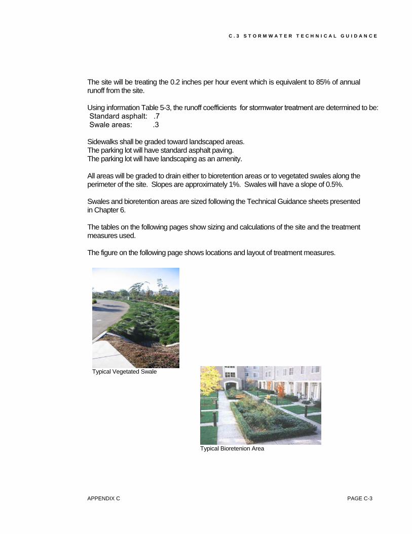
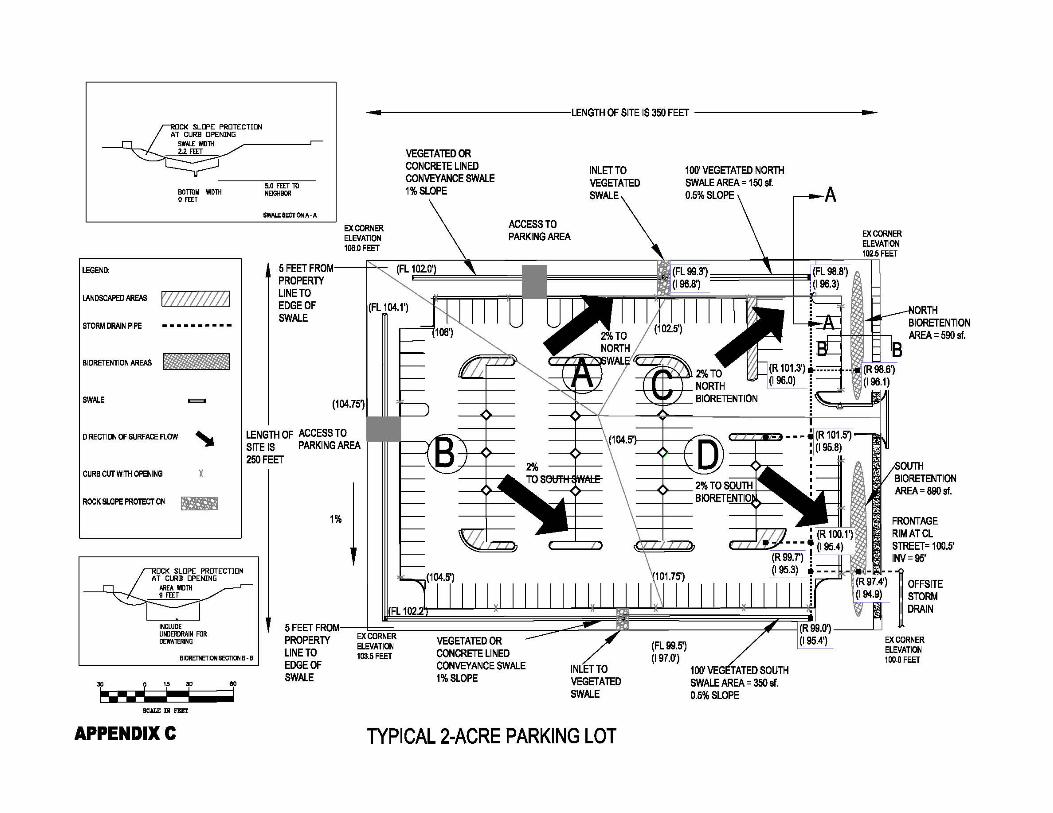
The site will be treating the 0.2 inches per hour event which is equivalent to 85% of annual runoff from the site. Using information Table 5-3, the runoff coefficients for stormwater treatment are determined to be: Standard asphalt: .7 Swale areas: .3 Sidewalks shall be graded toward landscaped areas. The parking lot will have standard asphalt paving. The parking lot will have landscaping as an amenity. All areas will be graded to drain either to bioretention areas or to vegetated swales along the perimeter of the site. Slopes are approximately 1%. Swales will have a slope of 0.5%. Swales and bioretention areas are sized following the Technical Guidance sheets presented in Chapter 6. The tables on the following pages show sizing and calculations of the site and the treatment measures used. The figure on the following page shows locations and layout of treatment measures.
Typical Vegetated Swale
Typical Bioretenion Area
APPENDIX C PAGE C-3

S A N M A T E O C O U N T Y W I D E W A T E R P O L L U T I O N P R E V E N T I O N P R O G R A M
Procedure for BMP sizing:
1. List areas under land type.
2. List areas that drain to each outfall.
3. Compute or locate runoff coefficient from Table 5-3 in Chapter 5.
4. Calculate flows to each outfall using Rational Method = Q (flow) = A (areas) * C (runoff coefficient) * I (intensity = 0.2 inches per hour for treatment event). This will be the flow that needs to be treated by a swale (a flow-based BMP). In the case of bioretention (a volume-based BMP that shares characteristics with a flow-based measure), simply measure the impervious surface as in the first 2 steps, then multiply by a sizing factor of 0.04.
5. If using a flow-based treatment measure, then use the Swale Worksheet provided.
6. Flow is from the above Rational Formula Q value.
7. Approximate slope to the proposed slope of the location of the flow-based treatment measure. This is to reduce the need of excess excavation. The minimum slope of a swale is 0.05 feet / feet.
8. Flow depth can vary depending on conditions the grasses in the swale will be kept. The value of 4 inches (0.33 feet) can be used for seldom-mowed bunch grasses, for often-mowed grass use 2 inches (.15 feet).
9. Manning’s Roughness is set at 0.25.
10. Sideslope should be a maximum of 3:1.
11. Residence Time is stated as 8 minutes required for concentrated flows, and 12 minutes if flows are dispersed through multiple inlets to the swale.
12. Bottom width will then need to be adjusted until the swale size allows for the treatment flow to be contained within the swale (last column).
13. Calculated top width is the bottom width plus 2 times the product of flow depth and sideslope.
14. Manning’s open channel formula is then used to calculate the flow in the swale.
15. A swale length of 100 feet is recommended, even a swale with less than 100 feet of length were sized to handle the treatment flow.
16. It is acceptable to use the results of the above calculations, even if the result is a swale treatment area that is less the 4% of the site. Four percent (4%) is a conservative guideline for the purpose of review.
PAGE C-4 APPENDIX C

SAN MATEO COUNTYWIDE WATER POLLUTION PREVENTION PROGRAM
Drainage Areas & Proposed Runoff FlowLand Type Coefficient @ 0.2 inches per hour
(square feet) (acres) (cfs)
Landscaping Self Treated 420 minorAREA A
to North SwaleLandscaping 7,448 0.17 0.1 0.00
Paving 6,368 0.15 0.7 0.02Treatment Flow to North Swale 13,816 0.32 0.02
AREA Bto South Swale
Landscaping 11,497 0.26 0.1 0.01Paving 24,491 0.56 0.7 0.08
Treatment Flow to South Swale 35,988 0.83 0.08AREA C
to North BioretentionLandscaping 3,222 0.07 0.1 0.00
Paving 11,442 0.26 0.7 0.04Treatment Flow to North Bioretention 14,664 0.34 0.04
AREA D to South Bioretention
Landscaping 3,877 0.09 0.1 0.00Paving 18,265 0.42 0.7 0.06
Treatment Flow to South Bioretention 22,142 0.51 0.06
Total 173,640 2.0 0.21
(1) Runoff Coefficients are from Start at the Source Handbook. (2) Table 5-3 Runoff Coefficients were used(3) Self Treating areas are flowing through swale and are therefore included in sizing of swale. (4) See Bioretention and Vegetated Swale C.3 Stormwater Guidance Documents
Treated By Area Area Sizing Proposed Treatment Actual Treatment Treatment Measure Treated Treated Guidelines Measure Size Measure Size
(square feet) (acres) (square feet) (square feet)
North Vegetated Swale 13,816 0.32 Swale (1) 553 154South Vegetated Swale 35,988 0.83 Worksheet 1440 347
North Bioretention Area 14,664 0.34 Bioretention 587 590South Bioretention Area 22,142 0.51 Worksheet 886 890
Total 86,610 2.0 3464 1981
(1) See Tables C-1C and C-1D C.3 Permit Swale Conformance Worksheet(2) See Tables C-1E and C-1F C.3 Permit Bioretention Conformance Worksheet(3) Sizing factor is storm intensity 0.2 inches/hour / infiltration rate 5 inches/hour = .04 which is unit less.
Table C-1B
Table C-1A Parking Lot Example Flow Calculations
Area of Land Type
Appendix C PAGE C-5

SAN MATEO COUNTYWIDE WATER POLLUTION PREVENTION PROGRAM
VARIABLES Input Comments
Treatment Flow 0.02 cfs from Table C-1AVegetated Swale Slope (feet/foot) 0.005 * 0.5% slopeFlow Depth (feet) 0.26 0.33 feet maximum, 4 inches of mowed grass, adjusted for treatment flowManning's Roughness 0.25 0.25 for 6 inch grasses, 0.20 for mowed lawn.Sideslope (H:V) 3 3:1 is recommended.Residence Time (minutes) 12 8 minutes if 90% collected at upstream limit, 12 minutes if interspersed.Bottom Width 0 Adjust until Flow in vegetated swale is greater than Treatment Flow.
RESULTS:
Vegetated Swale Hydraulics
Vegetated Manning's Calculated FlowSwale Bottom Flow Roughness Top inSlope Width Depth n Sideslope Width Vegetated Swale
(feet per foot) (feet) (feet) (feet per foot) (feet) (cfs)0.005 0.0 0.26 0.25 3 1.5 0.020
Minimum Vegetated Swale Length
Calculated UsedVegetated Swale Vegetated Swale
Residence Time Length Length(minutes) (feet) (feet)
12 96 100 *minimum vegetated swale length is 100 feet
Vegetated Swale Dimensions
Flow Wetted Flow Surface Portion of Area Percentage of Area Perimeter Velocity Area Dedicated to BMP Impervious Area
(square feet) (feet) (feet/sec) (square feet) (%) (%)0.20 1.62 0.10 154 1.1% 2.4%
(1) Proceedures are specified in the example.
Table C-1C - (Area A) Swale Worksheet
APPENDIX C PAGE C-6

SAN MATEO COUNTYWIDE WATER POLLUTION PREVENTION PROGRAM
VARIABLES Input Comments
Treatment Flow 0.084 cfs from Table C-1AVegetated Swale Slope (feet/foot) 0.005 * 0.5% slopeFlow Depth (feet) 0.33 0.33 feet maximum, 4 inches of mowed grass, adjusted for treatment flowManning's Roughness 0.25 0.20 for mowed lawn, 0.25 for 6 inch grasses.Sideslope (H:V) 3 3:1 is recommended.Residence Time (minutes) 12 8 minutes if 90% collected at upstream limit, 12 minutes if interspersed.Bottom Width 0.76 Adjust until Flow in Vegetated Swale is greater than Treatment Flow.
RESULTS:
Vegetated Swale Hydraulics
Manning's Calculated FlowVegetated Swale Bottom Flow Roughness Top in
Slope Width Depth n Sideslope Width Vegetated Swale(feet per foot) (feet) (feet) (feet per foot) (feet) (cfs)
0.005 0.8 0.33 0.25 3 2.7 0.084
Minimum Vegetated Swale Length
Calculated UsedVegetated Swale Vegetated Swale
Residence Time Length Length(minutes) (feet) (feet)
12 127 127 *minimum vegetated swale length is 100 feet
Vegetated Swale Dimensions
Flow Wetted Flow Surface Portion of Area Percentage of Area Perimeter Velocity Area Dedicated to BMP Impervious Area
(square feet) (feet) (feet/sec) (square feet) (%) (%)0.58 2.85 0.15 347 1.0% 1.4%
(1) Proceedures are specified in the example.
Stormwater C.3. Permit Vegetated Swale Conformance Worksheet
Table C-1D - (Swale B) Swale Worksheet
APPENDIX C PAGE C-7
SAN MATEO COUNTYWIDE WATER POLLUTION PREVENTION PROGRAM
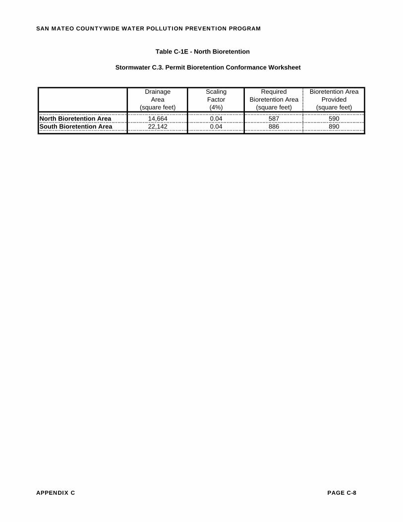
Drainage Scaling Required Bioretention AreaArea Factor Bioretention Area Provided
(square feet) (4%) (square feet) (square feet)
North Bioretention Area 14,664 0.04 587 590South Bioretention Area 22,142 0.04 886 890
Table C-1E - North Bioretention
Stormwater C.3. Permit Bioretention Conformance Worksheet
APPENDIX C PAGE C-8

S A N M A T E O C O U N T Y W I D E W A T E R P O L L U T I O N P R E V E N T I O N P R O G R A M
C.2 Podium Type Building Example1 Introduction
This example project shows a typical proposed podium type building in San Mateo County, with typical treatment measures as described in this document. This example will show multiple treatment measures to treat stormwater runoff being generated by the site.
Typical Podium Building
Summary of Stormwater Controls Site Design Measures Multistory building
above covered parking
Source Controls Covered trash
storage areas Landscape
designer will be asked to follow Integrated Pest Management Principles
Treatment Measures Flow-through
planters
The example podium style building site description: The project site is approximately 25,000 square feet. The site has Type D soil with expected compaction of 95%. Lot line is assumed to be the edge of the city right-of-way (sidewalks).
1 This example project is based on an example project in the Alameda Countywide Clean Water Program’s C.3 Stormwater Technical Guidance.
PAGE C-10 APPENDIX C

C . 3 S T O R M A T E R T E C H N I C A L G U I D A N C E
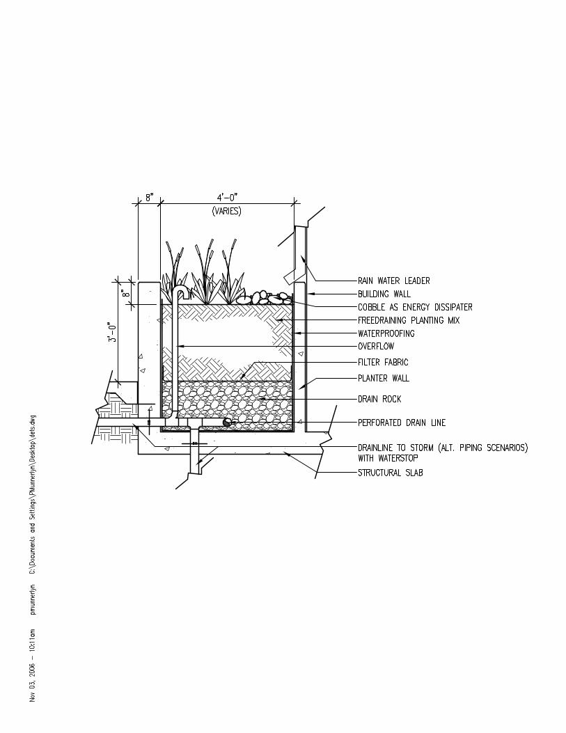
The proposed podium building is a zero lot line design with flow through planters in the center of the building around a concrete patio located on the roof of the second floor, and down at ground level along the sidewalk. The podium building is a mixed-use building with residential units on the top floors, retail sites on the second floor and parking on the bottom floor. The building mechanical facilities and trash facilities are also on the bottom floor. The roof area of the podium building consists of approximately 9,000 square foot patio, 1,000 square feet of flow-through planters and 15,000 square feet of roof. Off-site sidewalks and driveways will be graded toward the street. The site will be treating the 0.2 inches per hour event, which is equivalent to 85% of annual runoff from the site. Using information Table 5-3, the runoff coefficients are determined to be: Patio surfaces: .7 Roof surfaces: .9 Flow-through planter: .1 The ground floor is a concrete slab with buildings and a covered parking structure. There is no potential for infiltration. The soils within the planter will be at least 18 inches of loamy sand that must pass an in-situ percolation test with a rate of 5 inches/hour. A 6-inch layer of planting soil will be paced on the loamy sand to encourage plant growth. A 12-inch layer of drain rock will be placed around the perforated underdrain to allow for dewatering of the flow-through planter. The flow-through planter areas will connect directly to the storm drain system through a
system of perforated underdrains and overflow pipes.
Typical Flow-Through Planter
Flow-through planter areas will connect directly to the storm drain system through a system of perforated underdrains and overflow pipes. Flow-through planters shall be sized to be 4% of the area of the impervious patio. The flow –through planter shall have splash blocks at rainwater leader discharge points to protect against erosion.
The tables on the following pages show the sizes and calculations for the podium building treatment measures.
APPENDIX C PAGE C-11

S A N M A T E O C O U N T Y W I D E W A T E R P O L L U T I O N P R E V E N T I O N P R O G R A M
Source Control Parking and trash shall be under the building and covered. Procedure for BMP sizing:
1. List areas under land type.
2. List areas that drain to each outfall.
3. In the case of a flow-through planter (a volume-based treatment measure), simply measure the impervious surface as in the first 2 steps, the multiply by a sizing factor of 0.04. The 4% ratio is for planning review and is from 0.2 inches of rainfall per hour inflow versus 5 inches/hour infiltration rate.
PAGE C-12 APPENDIX C

SAN MATEO COUNTYWIDE WATER POLLUTION PREVENTION PROGRAM
Proposed Area Area Sizing Required Treatment Provided Treatment Land Type Treated Treated Guidelines Measure Measure
(square feet) (acres) (square feet) (square feet)
Concrete Roof Top 9,000 0.21 Flow Through 360 360Patio to Ground Floor Planter Planters Volume
Method MultiplyRoofs to Roof Top Planters 15,000 0.34 Area by 0.04 (1) (3) 600 600
Roof Top Flow (2) 1,000 0.02 Self Treating 0 0Through Planters
Total 25,000 0.57
(1) See Flow Through Planter C.3 Stormwater Guidance Documents(2) Flow through planter box areas are included in the sizing of the treatment measure. (3) Sizing guidline for Flow through planters is 0.04. Area treated 9,000 sf x 0.04 = 360 sf.(4) Procedures are specified in the example.
Table C-2A Example 2 Podium Type Structure Sample Calculations, Treatment Measure Sizing
APPENDIX C PAGE C-13


S A N M A T E O C O U N T Y W I D E W A T E R P O L L U T I O N P R E V E N T I O N P R O G R A M
C.3 Zero Lot Line Building Introduction
This example shows a typical zero lot line building in San Mateo County. The project proposes using a flow-through planters and media filter. Flow-through planters are sized using the method provided in Example C.2. Media filter sizing is typically provided by the manufacturer. An example checklist is provided demonstrating possible performance specifications or guidelines for the selection of an underground stormwater treatment device.
Typical Zero Lot Line Building, City of San Mateo
Summary of Stormwater Controls Site Design Measures Multistory building reduces
impervious surfaces Flow-through planter offers
both stormwater treatment and aesthetically-pleasing seasonal water feature
Source Controls Covered trash and recycling
storage areas Treatment Measures Flow-through planters Media filter
PAGE C-16 APPENDIX C

C . 3 S T O R M A T E R T E C H N I C A L G U I D A N C E
Possible Performance Specifications or Guidelines for the Selection of an Underground Stormwater Treatment Device GENERAL USE: It is understood that the use of manufactured or prefabricated underground stormwater treatment devices should generally be discouraged in favor of above ground passive treatment measures such as flow-through planters, vegetated buffer strips and swales, detention basins, bioretention basins, infiltration trenches, and tree well filters whenever possible. However, when these preferred treatment measures are not sufficient, or feasible due to space, land use and/or topographic constraints, the alternative use of underground stormwater treatment devices would be considered, providing the following requirements and conditions are satisfied. REQUIREMENTS: The applicant will meet the following requirements, complete and submit the checklist to the reviewing agency prior to consideration/approval of allowing the use of underground stormwater treatment devices: Project Name: Project Land Use: Reason for using underground stormwater treatment unit:: Insufficient open space for above ground treatment:: Topography constraints: Land use constraints: Total site acreage: % Impervious: Treated Flow: Peak Flow: Runoff to be treated will be from: Vehicular parking-storage, drive aisles: Roof top: Green roof: Truck loading dock: Primary Target Pollutant: Treatment Device: Soluble metals, fine silt & total nutrients: Media filtration Coarse silt, sand: Hydrodynamic separator Trash, debris and coarse sand: Screening Oil: Oil/water separator Model and Manufacturer of Treatment Unit(s):
APPENDIX C PAGE C-17

S A N M A T E O C O U N T Y W I D E W A T E R P O L L U T I O N P R E V E N T I O N P R O G R A M
Does device have a self-cleaning mechanism? Yes____ No ___
Is pretreatment needed? Yes____ No ___
Does device have a pretreatment bay separate from the cartridge bay? Yes____ No ___
Does device have drain-down capability (vector control)? Yes____ No ___
Is underdrain system exposed (as opposed to part of cartridge bay? Yes____ No Does the device have multivalve capability? (I.e., if a valve on a media filtration cartridge fails, the other cartridges are not rendered useless.) Yes____ No ____ Does the device have an overflow bypass? Yes____ No ____ Internal or external bypass? Anticipated Maintenance interval? East accessibility to Cartridge bay? Yes____ No ____ TSS Removal Efficiency: Total Phosphate Removal Efficiency: Total Nitrate Removal Efficiency: Cartridge filtration rate: (gpm) Does Manufacturer provide O&M guidelines that can be included in Maintenance Agreement? Yes____ No ____ Was the Manufacturer consulted on the design and selection of this unit for this site? Yes____ No ____ Provide certification from Manufacturer or Manufacturer’s representative: “We certify our participation in the completion of this checklist, the review of the proposed use and model selected, treatment requirements and capabilities, and to provide the owner, design professional and contractor with technical support in its design, installation, operation and maintenance phases to ensure it will function as warranted.” Name Company Title Date
PAGE C-18 APPENDIX C


S A N M A T E O C O U N T Y W I D E W A T E R P O L L U T I O N P R E V E N T I O N P R O G R A M
C.4 Retail Gasoline Outlet Example Introduction
This example shows a typical proposed gas station in San Mateo County, with typical treatment measures as described in this document. This example shows multiple treatment measures to treat stormwater runoff being generated by the site.
Summary of Stormwater Controls Site Design Measures Total containment of site runoff Covered pump islands and trash
enclosures Hydrocarbon sensor and diversion
valve and fuel spill chamber Source Controls Effective and regular housekeeping
of site, i.e. sweeping and spill cleanup.
Landscape designer will be asked to follow Integrated Pest Management Principles for landscape and vegetated swale areas
Treatment Measures Vegetated swales Media–filtration vault Canopy to extend 10 feet beyond the
pump area. The canopy shall not drain onto the fueling area.
Fueling area to have impermeable surface of Portland cement concrete or equivalent smooth surface, graded at the minimum slope necessary to prevent ponding, and shall be graded to prevent run-on from the rest of the site to the maximum extent possible.
Typical Gas Station Site
PAGE C-24 APPENDIX C

C . 3 S T O R M W A T E R T E C H N I C A L G U I D A N C E
The example gas station site description: The project site is 13,200 square feet with 2% pavement slope to drains. The site has multiple ingress/egress points. The site will be treating the 0.2 inches per hour event which is equivalent to 85% of annual runoff from the site. Using information Table 5-3, the runoff coefficients are determined to be: Standard Asphalt: .7 Swale areas: .3 The gas station site will have standard asphalt (runoff coefficient of .7) and concrete paving (runoff coefficient of .8) . The gas station site will have landscaping as an amenity. All areas will be graded to drain either to grates connected to the storm drain outletting to the media-filtration vault, or to vegetated swale along the one side of the site. Slopes are approximately 2%. Swales will have a slope of 0.5%. Swales and bioretention areas are sized following the Technical Guidance sheets presented in Chapter 6. The tables on the following pages show sizing and calculations of the site and the treatment measures used. The figure on the following page shows locations and layout of treatment measures.
Typical Vegetated Swale
APPENDIX C PAGE C-25

S A N M A T E O C O U N T Y W I D E W A T E R P O L L U T I O N P R E V E N T I O N P R O G R A M
Procedure for BMP Sizing:1. List areas under land type. 2. List areas that drain to each outfall. 3. Compute or locate runoff coefficient from Table 5-3 in Chapter 5. 4. Calculate flows to each outfall using Rational Method = Q (flow) = A (areas) * C (runoff
coefficient) * I (intensity = 0.2 inches per hour for treatment event). This will be the flow that needs to be treated by a swale (a flow-based BMP). In the case of bioretention (a volume-based BMP that shares characteristics with a flow-based measure), simply measure the impervious surface as in the first 2 steps, then multiply by a sizing factor of 0.04.
5. If using a flow-based treatment measure, then use the Swale Worksheet provided. 6. Flow is from the above Rational Formula Q value. 7. Approximate the slope of the flow-based treatment measure at the proposed location.
This is to reduce the need of excess excavation. The minimum slope of a swale is 0.05 feet / feet.
8. Flow depth can vary depending on design conditions and the height of the grass in the swale. The value of 4 inches (0.33 feet) can be used for seldom-mowed bunch grasses, for often-mowed grass use 2 inches (.15 feet).
9. Manning’s Roughness is set at 0.25 for seldom-mowed grass. 10. Side slope should be a maximum of 3H:1V. 11. Residence Time is stated as 8 minutes required for concentrated flows, and 12 minutes
if flows are dispersed through multiple inlets to the swale. 12. Bottom width will then need to be adjusted until the swale size allows for the treatment
flow to be contained within the swale (last column). 13. Calculated top width is the bottom width plus 2 times the product of flow depth and side
slope. 14. Manning’s open channel formula is then used to calculate the flow in the swale. 15. A swale length of 100 feet is recommended, even if it exceeds the minimum required
calculated swale length. 16. It is acceptable to use the results of the above calculations, even if the result is a swale
treatment area that is less the 4% of the site. Four percent (4%) is a conservative guideline for the purpose of review.
17. For sizing, selection and design of media filtration vaults and such items as hydrocarbon sensors, diversion valves and fuel spill chambers, consult manufacturer’s guidelines and requirements of said structures, and requirements for such structures outlined in this manual.
PAGE C-26 APPENDIX C

San Mateo Countywide Water Pollution Prevention Program
Table 1A Gas Station Vegetated Swale Example Flow Calculations
Drainage Areas & Proposed
Land Type Area of Land Type
(square feet)
(acres)
Runoff Coefficient
Flow @0.2 inches per hour
(cfs)
Landscaping Self Treated AREA A To Swale
Standard Asphalt Paving
500
4,300
Minor
0.103
.7
0.0145
Total 4,300 0.103 0.0145
(1) Runoff Coefficients are from Start at the Source Handbook. (2) Table 5-3 Runoff Coefficients were used (3) Self Treating areas are flowing through swale and are therefore included in sizing of swale. (4) See Vegetated Swale C.3 Stormwater Guidance Documents.
Table 1B
Treated By Treatment Measure
Area Treated
(square
feet)
Area Treated
(acres)
Sizing Guidelines
Proposed Treatment Measure Size (square feet)
Actual Treatment Measure
Size
(square feet) Vegetated Swale
for Area A
4,300
0.103 Swale (1)
Worksheet
180
308 Total 4,300 0.103 180 308
(1) See Tables 1C and 1D C.3 Permit Swale Conformance Worksheet (2) Sizing factor is storm intensity 0.2 inches/hour / infiltration rate 5 inches/hour = .04 which is
unit less.
