ex polyester flansch 8p
DESCRIPTION
Rose- Junction Box GRPTRANSCRIPT
65
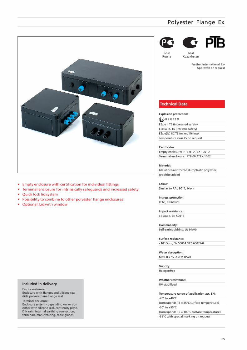
Polyester Flange Ex
• Empty enclosure with certification for individual fittings• Terminal enclosure for intrinsically safeguards and increased safety• Quick lock lid system• Possibility to combine to other polyester flange enclosures• Optional: Lid with window
Included in deliveryEmpty enclosure:Enclosure with flanges and silicone seal(lid), polyurethane flange seal
Terminal enclosure:Enclosure system - depending on versioneither with silicone seal, continuity plate,DIN rails, internal earthing connection,terminals, manufcturing, cable glands
Technical Data
Explosion protection:
II 2 G / 2 D
EEx e II T6 (increassed safety)
EEx ia IIC T6 (intrinsic safety)
EEx e(ia) IIC T6 (mixed fitting)
Temperature class T5 on request
Certificates:
Empty enclosure: PTB 01 ATEX 1061U
Terminal enclosure: PTB 00 ATEX 1002
Material:
Glassfibre-reinforced duroplastic polyester,
graphite added
Colour:
Similar to RAL 9011, black
Ingress protection:
IP 66, EN 60529
Impact resistance:
>7 Joule, EN 50014
Flammability:
Self-extinguishing, UL 94/V0
Surface resistance:
<109 Ohm, EN 50014 / IEC 60079-0
Water absorption:
Max. 0.7 %, ASTM D570
Toxicity:
Halogenfree
Weather resistance:
UV-stabilized
Temperature range of application acc. EN:
-20° to +40°C
(corresponds T6 = 85°C surface temperature)
-20° to +55°C
(corresponds T5 = 100°C surface temperature)
-55°C with special marking on request
Further international Ex-Approvals on request
GostRussia
GostKazakhstan
66
Polyester Flange Ex
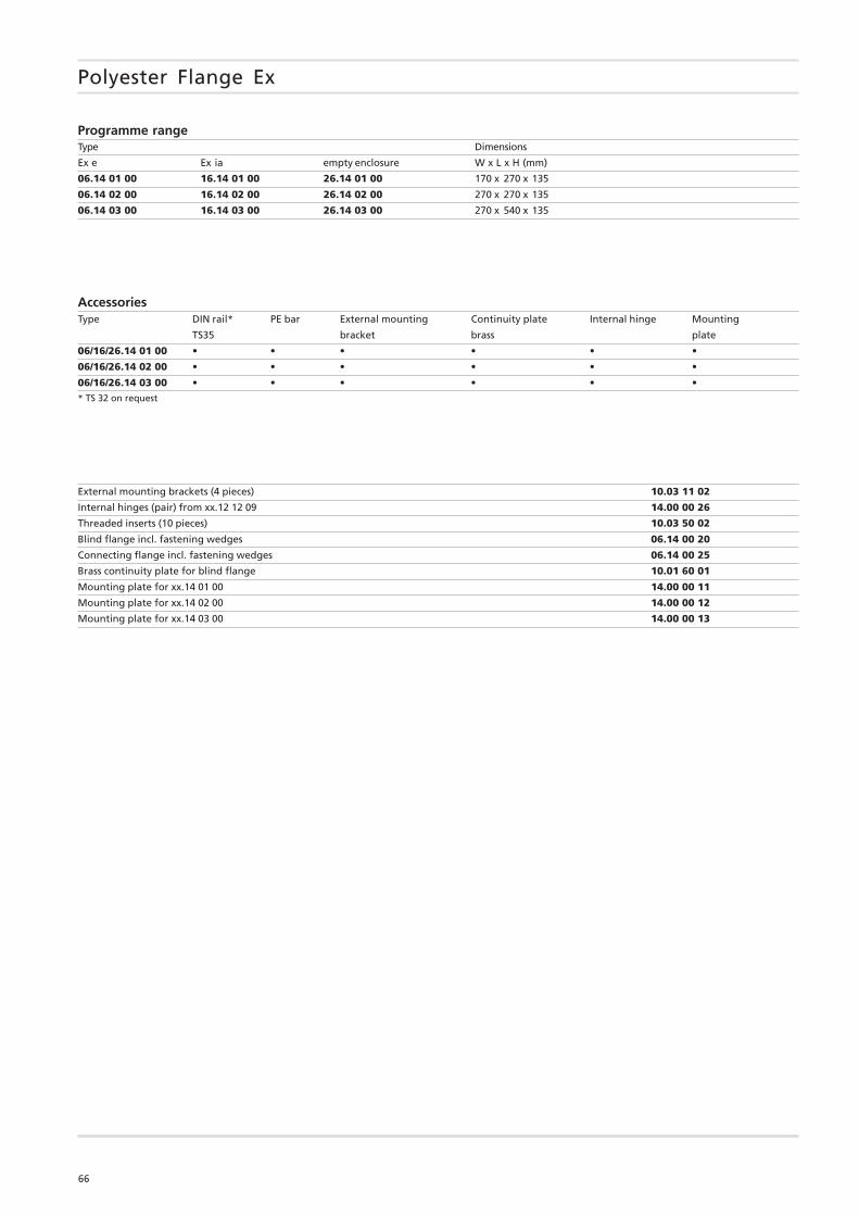
Programme rangeType Dimensions
Ex e Ex ia empty enclosure W x L x H (mm)
06.14 01 00 16.14 01 00 26.14 01 00 170 x 270 x 135
06.14 02 00 16.14 02 00 26.14 02 00 270 x 270 x 135
06.14 03 00 16.14 03 00 26.14 03 00 270 x 540 x 135
AccessoriesType DIN rail* PE bar External mounting Continuity plate Internal hinge Mounting
TS35 bracket brass plate
06/16/26.14 01 00 • • • • • •
06/16/26.14 02 00 • • • • • •
06/16/26.14 03 00 • • • • • •* TS 32 on request
External mounting brackets (4 pieces) 10.03 11 02
Internal hinges (pair) from xx.12 12 09 14.00 00 26
Threaded inserts (10 pieces) 10.03 50 02
Blind flange incl. fastening wedges 06.14 00 20
Connecting flange incl. fastening wedges 06.14 00 25
Brass continuity plate for blind flange 10.01 60 01
Mounting plate for xx.14 01 00 14.00 00 11
Mounting plate for xx.14 02 00 14.00 00 12
Mounting plate for xx.14 03 00 14.00 00 13
67
Polyester Flange Ex
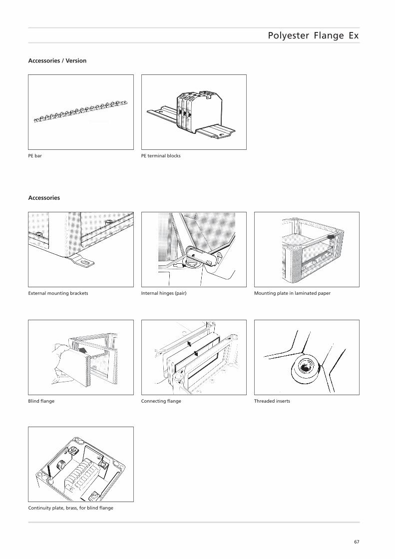
PE bar PE terminal blocks
Internal hinges (pair) Mounting plate in laminated paper
Continuity plate, brass, for blind flange
Blind flange Connecting flange
External mounting brackets
Threaded inserts
Accessories / Version
Accessories
68
Polyester Flange Ex
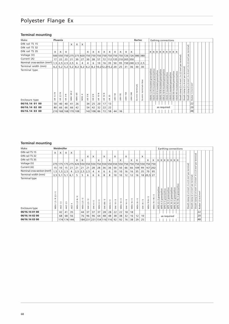
Make Phoenix Bartec
DIN rail TS 15
DIN rail TS 32
DIN rail TS 35
Voltage (V)
Current (A)
Nominal cross-section (mm²)
Terminal width (mm)
Terminal type
Enclosure type
06/16.14 01 0006/16.14 02 0006/16.14 03 00
Terminal mounting
UK
1,5
N
UK
2,5
N
UK
3 N
MB
K 3
/E-Z
MB
K 6
/E
MX
K 4
UK
5 N
UK
6 N
UK
10
N
UK
16
N
UK
35
UK
H 5
0
UK
H 9
5
UK
H 1
50
UK
H 2
40
Ex-m
ini
term
inal
s
Ex-m
ini
term
inal
s b
lue
X X X
X X X X X X X X X X X X
500 550 750 275 275 420 750 750 750 750 750 750 750 726 726 380 380
17 22 23 21 39 27 30 38 57 72 112 135 210 265 350
1,5 2,5 2,5 2,5 6 4 4 6 10 16 35 50 95 150 240 2,5 2,5
4,2 5,2 5,2 5,2 8,2 6,2 6,2 8,2 10,212,215,2 20 25 31 36 30 30
Eathing connections
USL
KG
1,5
N in
sula
ted
gre
en/y
ello
w
USL
KG
2,5
N in
sula
ted
gre
en/y
ello
w
USL
KG
6 N
insu
late
d g
reen
/yel
low
USL
KG
10
N in
sula
ted
gre
en/y
ello
w
USK
LG 1
6 N
insu
late
d g
reen
/yel
low
USL
KG
3 in
sula
ted
gre
en/y
ello
w
USL
KG
5 in
sula
ted
gre
en/y
ello
w
USL
KG
50
insu
late
d g
reen
/yel
low
USL
KG
95
insu
late
d g
reen
/yel
low
X X X X X X X X X
22
20
48
50 40 40 41 26 34 25 20 17 13
80 66 66 66 42 54 42 32 22 22
210 168 168 170 108 142 108 86 72 58 44 36
Shea
th c
lam
p (
2 x
4 m
m²,
3 x
2,5
mm
² p
er t
erm
inal
)
Shea
th c
lam
p (
2 x
4 m
m²
per
ter
min
al)
Shea
th c
lam
p (
2 x
6 m
m²,
3 x
4 m
m²,
4 x
2,5
mm
² p
er t
erm
inal
)
Bu
sbar
1,5
to
6 m
m²
as required
Make Weidmüller
DIN rail TS 15
DIN rail TS 32
DIN rail TS 35
Voltage (V)
Current (A)
Nominal cross-section (mm²)
Terminal width (mm)
Terminal type
Enclosure type
06/16.14 01 0006/16.14 02 0006/16.14 03 00
Terminal mounting
WD
U 1
,5 /
R 3
,5 /
E
AK
Z 1,
5
AK
Z 2,
5
AK
Z 4
WD
U 2
,5 N
/ E
WD
U 2
,5 /
E
SAK
2,5
/ E
SAK
4 /
E
WD
U 4
/ E
SAK
6N
/ E
WD
U 6
/ E
SAK
10
/ E
WD
U 1
0 /
E
SAK
16
/ E
WD
U 1
6 /
E
WD
U 3
5 /
E
SAK
35
/ E
WD
U 7
0 N
/ E
WD
U 7
0 /
95 /
EX X X X
X X X X X X
X X X X X X X X X
275 175 175 275 420 550 550 550 750 550 550 550 550 750 750 750 550 750 750
15 10 15 21 21 21 21 28 28 36 36 50 50 66 66 109 99 167 202
1,5 1,5 2,5 4 2,5 2,5 2,5 4 4 6 6 10 10 16 16 35 35 70 95
3,5 5,1 5,1 6,1 5 5 6 6 6 8 8 10 10 12 12 16 18 20,5 27
Earthing connections
WPE
2,5
/ E
gre
en/y
ello
w
WPE
4 /
E g
reen
/yel
low
WPE
6 /
E g
reen
/yel
low
WPE
10
/ E g
reen
/yel
low
WPE
16
/ E g
reen
/yel
low
WPE
35
/ E g
reen
/yel
low
WPE
70
/ 95
/ E g
reen
/yel
low
X X X X X X X
22
20
48
42 41 35 44 37 37 37 28 28 22 22 18 18
68 68 56 76 96 96 64 48 48 38 38 32 16 12 10
174 174 144 184 231 231 154 116 116 92 92 76 38 29 25
Shea
th c
lam
p (
2 x
4 m
m²,
3 x
2,5
mm
² p
er t
erm
inal
)
Shea
th c
lam
p (
2 x
4 m
m²
per
ter
min
al)
Shea
th c
lam
p (
2 x
6 m
m²,
3 x
4 m
m²,
4 x
2,5
mm
² p
er t
erm
inal
)
Bu
sbar
1,5
to
6 m
m²
as required
69
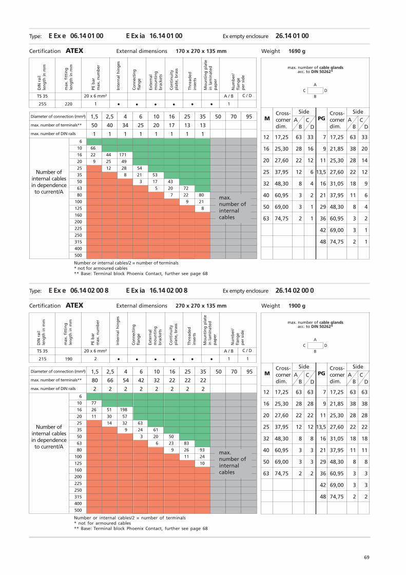
Type: E Ex e 06.14 01 00 E Ex ia 16.14 01 00 Ex empty enclosure 26.14 01 00
Certification ATEX External dimensions 170 x 270 x 135 mm Weight 1690 g
1,5 2,5 4 6 10 16 25 35 50 70 95
50 40 34 25 20 17 13 13
1 1 1 1 1 1 1 1
Type: E Ex e 06.14 02 00 8 E Ex ia 16.14 02 00 8 Ex empty enclosure 26.14 02 00 0
Certification ATEX External dimensions 270 x 270 x 135 mm Weight 1900 g
1,5 2,5 4 6 10 16 25 35 50 70 95
80 66 54 42 32 22 22 22
2 2 2 2 2 2 2 26
10 77
16 26 51 198
20 11 30 57
25 14 32 63
35 9 24 61
50 3 20 50
63 6 23 83
80 9 26 93
100 11 24
125 10
160
200
225
250
315
400
500
6
10 66
16 22 44 171
20 9 25 49
25 12 28 54
35 8 21 53
50 3 17 43
63 5 20 72
80 7 22 80
100 9 21
125 8
160
200
225
250
315
400
500
TS 35
255 220 •
DIN
rai
lle
ng
th in
mm
Thre
aded
inse
rts
Mo
un
tin
g p
late
in l
amin
ated
pap
er
Nu
mb
er/
flan
ge
per
sid
e
Exte
rnal
mo
un
tin
gb
rack
ets
PE b
arm
ax. n
um
ber
Inte
rnal
hin
ges
Co
nti
nu
ity
pla
te, b
rass
max
. fit
tin
gle
ng
th in
mm
Conn
ecti
ngfl
ange
C DA
B
CD
M AB
PG
12 17,25 63 33 7 17,25 63 33
16 25,30 28 16 9 21,85 38 20
20 27,60 22 12 11 25,30 28 14
25 37,95 12 6 13,5 27,60 22 12
32 48,30 8 4 16 31,05 18 9
40 60,95 3 2 21 37,95 11 6
50 69,00 3 1 29 48,30 8 4
63 74,75 2 1 36 60,95 3 2
42 69,00 3 1
48 74,75 2 1
CD
AB
•• • •
20 x 6 mm²
1 •
A / B
1
C / D
TS 35
215 190 •
C DA
B
CD
M AB
PG
12 17,25 63 63 7 17,25 63 63
16 25,30 28 28 9 21,85 38 38
20 27,60 22 22 11 25,30 28 28
25 37,95 12 12 13,5 27,60 22 22
32 48,30 8 8 16 31,05 18 18
40 60,95 3 3 21 37,95 11 11
50 69,00 3 3 29 48,30 8 8
63 74,75 2 2 36 60,95 3 3
42 69,00 3 3
48 74,75 2 2
CD
AB
•• • •
20 x 6 mm²
2 •
A / B
1
C / D
1
max. number of cable glandsacc. to DIN 50262*
Diameter of connection (mm²)
max. number of terminals**
max. number of DIN rails
Number ofinternal cablesin dependence
to current/A
Number or internal cables/2 = number of terminals* not for armoured cables** Base: Terminal block Phoenix Contact, further see page 68
Cross-cornerdim.
Cross-cornerdim.
SideSide
max.number ofinternalcables
DIN
rai
lle
ng
th in
mm
Thre
aded
inse
rts
Mo
un
tin
g p
late
in l
amin
ated
pap
er
Nu
mb
er/
flan
ge
per
sid
e
Exte
rnal
mo
un
tin
gb
rack
ets
PE b
arm
ax. n
um
ber
Inte
rnal
hin
ges
Co
nti
nu
ity
pla
te, b
rass
max
. fit
tin
gle
ng
th in
mm
Conn
ecti
ngfl
ange
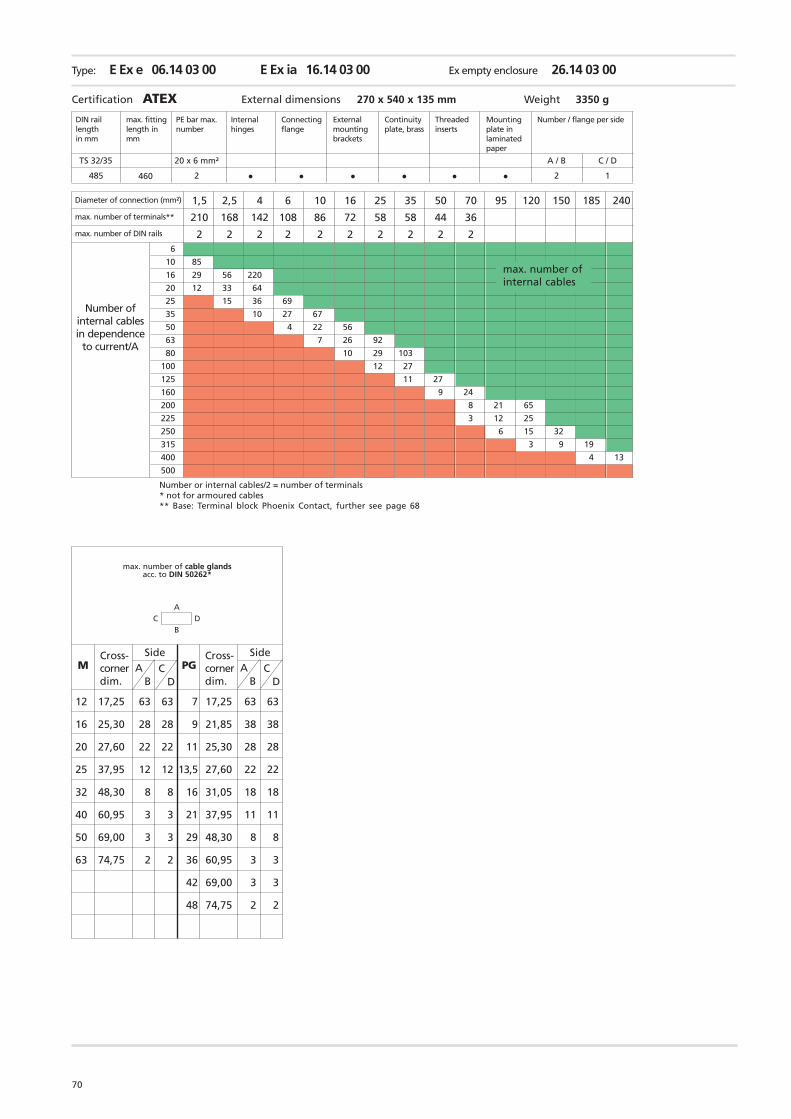
70
Type: E Ex e 06.14 03 00 E Ex ia 16.14 03 00 Ex empty enclosure 26.14 03 00
DIN raillengthin mm
Threadedinserts
Mountingplate inlaminatedpaper
Number / flange per sideExternalmountingbrackets
PE bar max.number
Internalhinges
Continuityplate, brass
Certification ATEX External dimensions 270 x 540 x 135 mm Weight 3350 g
1,5 2,5 4 6 10 16 25 35 50 70 95 120 150 185 240
210 168 142 108 86 72 58 58 44 36
2 2 2 2 2 2 2 2 2 2
max. fittinglength inmm
Connectingflange
TS 32/35
485 460 • •••
6
10 85
16 29 56 220
20 12 33 64
25 15 36 69
35 10 27 67
50 4 22 56
63 7 26 92
80 10 29 103
100 12 27
125 11 27
160 9 24
200 8 21 65
225 3 12 25
250 6 15 32
315 3 9 19
400 4 13
500
• •2
20 x 6 mm² C / D
2
A / B
1
C DA
B
CD
M AB
PG
12 17,25 63 63 7 17,25 63 63
16 25,30 28 28 9 21,85 38 38
20 27,60 22 22 11 25,30 28 28
25 37,95 12 12 13,5 27,60 22 22
32 48,30 8 8 16 31,05 18 18
40 60,95 3 3 21 37,95 11 11
50 69,00 3 3 29 48,30 8 8
63 74,75 2 2 36 60,95 3 3
42 69,00 3 3
48 74,75 2 2
CD
AB
max. number of cable glandsacc. to DIN 50262*
Diameter of connection (mm²)
max. number of terminals**
max. number of DIN rails
Number ofinternal cablesin dependence
to current/A
Number or internal cables/2 = number of terminals* not for armoured cables** Base: Terminal block Phoenix Contact, further see page 68
Cross-cornerdim.
Cross-cornerdim.
SideSide
max. number ofinternal cables
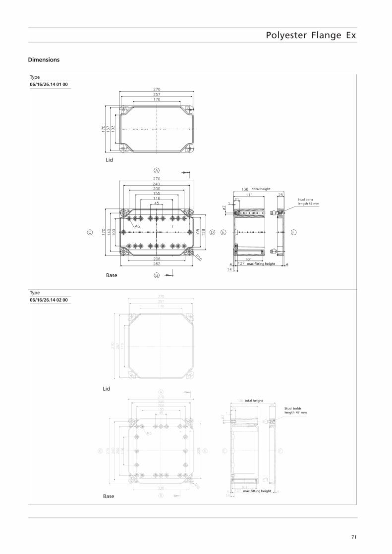
71
Polyester Flange Ex
Type
06/16/26.14 01 00
Type
06/16/26.14 02 00
total height
max.fitting height
Stud boltslength 47 mm
Lid
Base
total height
max.fitting height
Stud boldslength 47 mm
Lid
Base
Dimensions
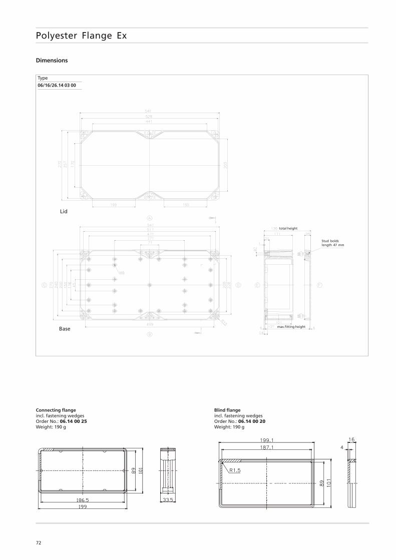
72
Connecting flangeincl. fastening wedgesOrder No.: 06.14 00 25Weight: 190 g
Blind flangeincl. fastening wedgesOrder No.: 06.14 00 20Weight: 190 g
Type
06/16/26.14 03 00
Polyester Flange Ex
total height
max.fitting height
Stud boldslength 47 mm
Lid
Base
Dimensions