evolutionary body building: adaptive physical designs for robots
TRANSCRIPT

Evolutionary Body Building:
Adaptive physical designs for robots
Pablo Funes and Jordan Pollack1
Computer Science DepartmentVolen Center for Complex Systems
Brandeis UniversityWaltham, MA 02254-9110
{pablo,pollack}@cs.brandeis.edu
Abstract
Creating artificial life forms through evolutionary robotics faces a “chicken and egg” problem:
learning to control a complex body is dominated by problems specific to its sensors and effectors,
while building a body that is controllable assumes the pre-existence of a brain.
The idea of co-evolution of bodies and brains is becoming popular, but little work has been
done in evolution of physical structure because of the lack of a general framework for doing it. Evo-
lution of creatures in simulation has usually resulted in virtual entities which are not buildable, while
embodied evolution in actual robotics is constrained by the slow pace of real time.
The work we present takes a step in the problem of body evolution by applying evolutionary
techniques to the design of structures assembled out of elementary components which stick together.
Evolution takes place in a simulator which computes forces and stresses and predicts stability of 3-
dimensional brick structures. The final printout of our program is a schematic assembly, which is
then built physically. We demonstrate the functionality of this approach to robot body building with
many evolved artifacts.
1. To appear inArtificial Life 4:4 (Autumn 1998)

2 Pablo J. Funes and Jordan B. Pollack
1. Introduction
Evolutionary Robotics has traditionally focused in evolving robot controllers to provide a given
robot platform — either real or simulated — with a custom brain that, once downloaded, produces an
adequate behavior. The process of adaptation through evolutionary search allows these artificial life
forms with evolved brains to perform in the environments they inhabit.
The observation can be made, however, that evolution of a creature’s controlling brain is just one
part of the problem of artificial evolution of life — a creature that adapts to an environment needs an ade-
quate body to inhabit. The body and brains of a robot should evolve together to constitute an adaptive
organism. This is the case in natural life forms where new actions require new capabilities in the body
along with the corresponding new brain functions to execute them.
Karl Sims’ work [35, 36] stands out as an example of how the combination of brain and structure
evolution with physically inspired simulation can give rise to complex agents that cope with difficult
domains. Following Ngo and Marks [31], Sims evolved virtual creatures that have both body design and
control programs created by an evolutionary computation process.
Despite their beautiful realism, Sims’ organisms are far from real. His simulations do not consider
the mechanical feasibility of the articulations between different elements, which in fact overlap each
other at the joints, nor the existence of real world mechanisms that could produce the forces responsible
for their movements. There was no attempt to constrain his simulations so real robots could be built.
That is the subject of our work.
1.1. Background and related work
The intention of co-evolving brains and morphology together for real robots has been around since
the dawn of evolutionary robotics. Cliff, Husbands and Harvey said in one of their first papers, “we advo-
cate [...] the concurrent evolution of visual sensor morphology and the control networks: separating mor-

Evolutionary Body Building 3
phology from control is [...] difficult to justify from an evolutionary perspective and potentially
misleading” [7, p. 3]. But evolution of robot bodies remains limited mostly to adjusting parameters of the
sensory configuration (sensor positioning, and direction, receptive fields, and so on). [8, 27]. Recent work
by Lund, Hallam and Lee [29] addresses some morphological issues, such as body size and wheel radius
together with evolution of a robot control program.
The field of Evolutionary Hardware, which does adaptation of reconfigurable electronics, makes a
strong claim, that evolution can take advantage of emergent physical properties of the medium which
human designers overlook [38]. Indeed, evolution in reconfigurable electronics, rather than in simulation
of electronics, has advantages in speed. But evolution in mechanical hardware is much slower than in
simulation — e.g. experiments which last a week [12]. While the argument for embodied evolution in
mechanical hardware is similar — that the evolved controllers can exploit all sorts of behaviors an engi-
neer cannot predict — we believe that it is obvious both in Sims’ work, and our own below, that evolving
in an interesting simulator of physics also results in the exploitation of emergent behaviors.
Our intention is to shed light onto the problem of evolving bodies for robots. In order to do so, we
set aside the issue of control. Rather than extending an existing setup for evolution of control we focus
solely on the evolution of complete physical structures whichcould be robot bodies.
Evolutionary body building is an area in need of basic research to identify techniques, features and
problems towards creating the tools required for the future incorporation of true adaptive physicality into
evolutionary robotics.
We believe that is not a matter of using advanced genetic algorithms or engineering a great deal of
previous knowledge into elaborate fitness functions; not even a sophisticated simulation is required. We
show how modular components can be easily represented and modeled to capture the relevant features of
the physics of composite structures.

4 Pablo J. Funes and Jordan B. Pollack
In order to obtain buildable bodies while keeping both computational and fabrication costs to the
minimum, our approach is to exploit the benefits of mass production, using available modular elements
— toy bricks in this case — capable of being assembled into arbitrary configurations. We have chosen
Lego1 bricks as a substrate. Legos are well known for their flexibility for crafting low cost, handy designs
of vehicles and structures (as in [39], for example). Their simple modular concept make Legos a good
ground for doing evolution of computer simulated structures which can be built and deployed.
Our simulation starts with a simple model of breakage and uses network flow algorithms to simu-
late whole structures. Addressing the most primitive problems first we are evolving elementary structural
properties such as solidity, lightness, resistance, shape.
Other fields, outside robotics, of course, bear on the problem of physical form for robotics: Evolu-
tionary Design, evolving design plans for complex shapes of plausible objects, and Structural Engineer-
ing, evolving optimal shapes under Finite Element Modelling (FEM) [41] simulation.
Evolutionary Design, that is, the utilization of evolutionary computation techniques for industrial
design, is a new research area where Peter Bentley’s Ph.D. Thesis [3] is ground-breaking work. Bentley
uses a GA to evolve shapes for solid objects directed by multiple fitness measures. His evolved designs
include tables, prisms, even vehicle profiles. Bentley’s search algorithms use combinations of fitness
measures (“Size”, “Mass”, “No Fragmentation”, “Flat Upper Surface”, “Supportiveness”, etc.) that
include some physical constraints, like center of mass positioning or total weight. Lacking a physical sim-
ulation model, he simply relies on suchad hoc measures to guide evolution in each case.
The Structural Engineering problem called “structural topology optimization” addresses finding an
optimal shape for a component, a piece of material that is to be subject to known stresses but at the same
time be as cheap, light or small as possible. Applications of GA’s to this problem [5, 34] use a genetic rep-
resentation of the space of all valid shapes and construct a FEM model to evaluate fitness. In [5] for
1. Lego is a registered trademark of the Lego group.

Evolutionary Body Building 5
example, the algorithm has to minimize weight and maximize stiffness of a beam at the same time, evolv-
ing the topology of the cross-section.
Four elements need to be put together to evolve bodies: simulation, representation, fitness measure
and evolutionary algorithm.
Our work incorporates a model of the physical properties of Lego structures into an evolutionary
process that freely combines bricks of different shape and size into structures that are evaluated by how
well they perform a desired function. The resulting objects are not based in common design knowledge
on how to build with brick toys; instead, the computer discovers stable structures on its own through the
interaction of the evolutionary search process and the physical model.
In the rest of this paper we introduce the problem of simulation first (section 2), then describe our
own simulator (3) and the GA used to evolve structures (4), results (5) and discussion (6 - 7).
2. Simulation for Evolution
The problem of simulation is a subject of active debate in the robotics community. Whereas simu-
lating presents enormous difficulties [4, 30], embodied evolution [12] is constrained by the slow pace of
Physical Simulation
Fitness Evaluation
Genetic Algorithm Representation
Virtual Entity

6 Pablo J. Funes and Jordan B. Pollack
real-time interaction. We agree with Jakobi [23] in going for simulation at the right level, aiming at the
aspects of reality that will insure robust, transferable behaviors.
In order to evolve both the morphology and behavior of machines which can be manufactured, one
must have a simulator that operates under several constraints, and a resultant controller which is adaptive
enough to cover the gap between simulated and real world.
A simulator for evolving morphology should have the following properties:
• Universal - the simulator should cover an infinite general space of mechanisms.
• Conservative - because simulation is never perfect, it should preserve a margin of safety.
• Efficient - it should be quicker to test in simulation than through physical production and test.
• Buildable - results should be convertible from a simulation to a real object
We have obtained some promising results working with 2D and 3D structures of Lego bricks using
a simulation based on an idealized representation. Our central concept is the maximum stress torque that
the union between a pair of bricks can resist. Given a Lego structure, is it possible that all the stresses
between every pair of joined bricks fall below their maximum? If the answer is yes, we predict that this
structure is capable of holding its own weight — therefore, it is buildable.
Our simulation for bricks has some similarities to FEM1 in that a network is created — a node for
every brick — and our stability equations are propagated throughout. Due to our simplified conception of
what a brick is — just a connection that propagates loads between joints — the equations we have to
1. The Finite Element Modelling (FEM) [41] in structural engineering, discretizes a body, approximating it
with a “mesh”, a network that substitutes a differential equation, of difficult solution, with a finite num-
ber of difference equations, evaluated at the nodes of the mesh.

Evolutionary Body Building 7
solve are interval formulas. This is closer to a QP1 representation than to standard structural/mechanical
engineering models.
Our group is working on other alternatives as well. One of them is to take a complete state of the art
mechanical/structural CAD/CAM software package and use it as a separate ‘black box’ to evaluate a
structure in simulated physics [21]. The trade-off is that, whereas simplified models can be better suited
for particular applications, general purpose tools may save a lot of time in conceiving and implementing
such specialized models.
3. Networks of Torque Propagation: Simulation of Brick Structures
The resistance of the plastic material (ABS-acrylonitrile butadiene styrene) of Lego bricks far sur-
passes the force necessary to either join two of them together or break their unions. This makes it possible
to conceive a model that ignores the resistance of the material and evaluates the stress forces over a group
of bricks only at their union areas. If a Lego structure fails, it will generally do so at the joints, but the
actual bricks will not be damaged.
This characteristic of Lego structures makes their discretization for modelling an obvious step.
Instead of imposing an artificial mesh for simulation purposes only, these structures are already made of
relatively large discrete units. A first simplification is thus to ignore the physical characteristics of the
bricks and study only those of their unions.
1. A classic field in AI, Qualitative Physics (QP), deals with mechanical and physical knowledge represen-
tation. A logical representation of a mechanism, such as a Heat Pump [13] or a String [17] is used to
obtain simulations, or envisionments, of the future behavior of the mechanism. Instead of complete
physical laws, simple rules lead to useful predictions.

8 Pablo J. Funes and Jordan B. Pollack
Our second simplification is to ignore bending effects. In standard structural analysis, the effects of
stress are observed as deformation of the original shape of a body. Here strain deformations are ignored
altogether.
3.1. Lego joints in two dimensions
We began considering two-dimensional structures, assuming that all the bricks are of width 1,
assembled in a plane. We observed that a ‘fulcrum’ effect, the angular torque exerted over such a joint,
constitutes the principal cause for the breakage of a stressed structure of Lego bricks. Our model
describes the system of static forces inside a complex structure of Lego bricks as a network of rotational
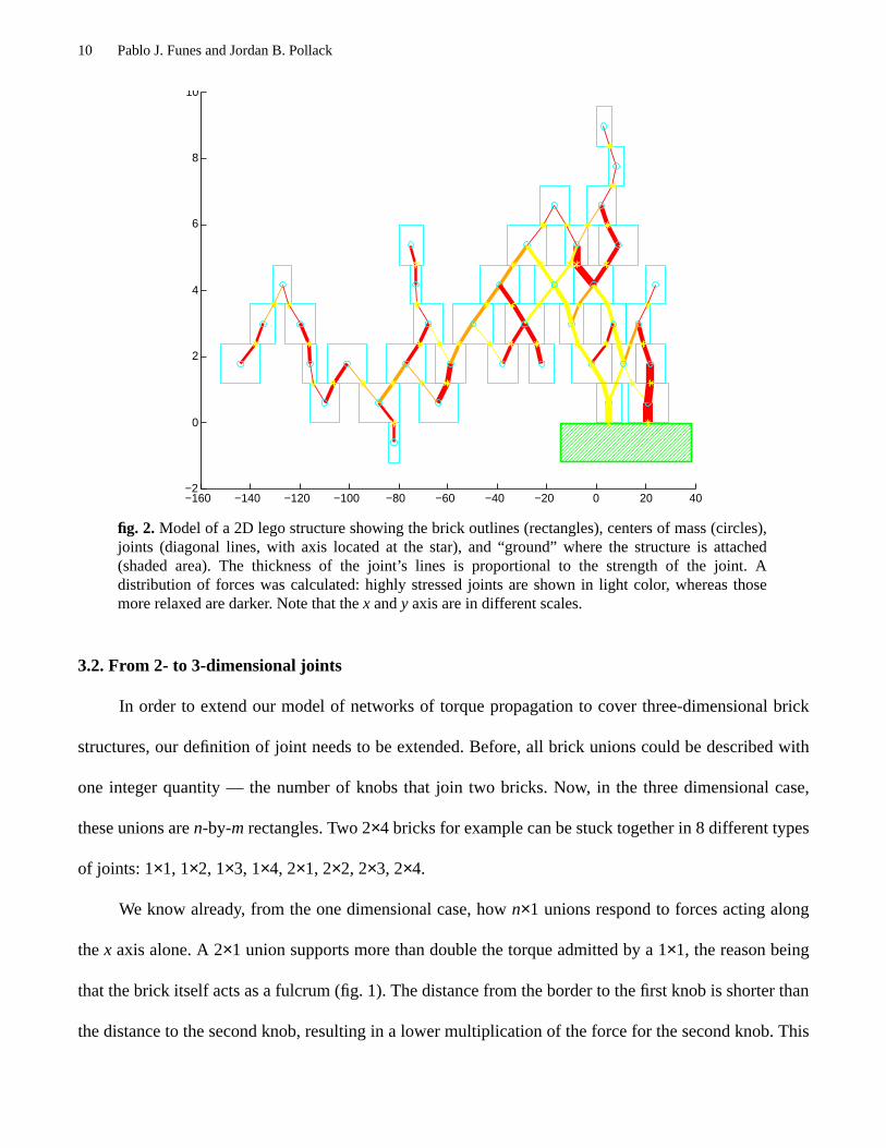
joints located at each union between brick pairs and subject to loads (fig. 2).
fig. 1.Fulcrum effect: a 2×1 union resists more than twice the load of a 1×1 because the second knobis farther away from the axis of rotation.
Bricks joined by just one knob resist only a small amount of torque; bigger unions are stronger. The
resistance of the joint should depend on the number of knobs involved. We measured the minimum
amount of stress that different linear (1×1, 2×1, 3×1, etc., as in fig. 1) unions of brick pairs support (table
1).
Given a structure formed by a combination of bricks, our model builds a network with joints of dif-
ferent capacities, according to the table. Each idealized joint is placed at the center of the area of contact

Evolutionary Body Building 9
between a pair of bricks. A margin of safety, set to 20% in our experiments, is discounted from the resis-
tances of all joints in the structure, to ensure robustness in the model’s predictions.
All forces acting in the structure have to be in equilibrium for it to be static. Each brick generates,
by its weight, a gravitational force acting downwards. There may be other forces generated by external
loads.
Each force acts has a site of application in one brick — e.g. each brick’s weight is a force applied to
itself — and has to be cancelled by one or more reaction forces for that brick to be stable. These reaction
forces can come from any of the joints that connect it to neighbor bricks. In that case the force is transmit-
ted through the joint to the connected brick. Thus, by the action-reaction principle, a load is propagated
through the network until finally absorbed by a fixed body — the ‘ground’.
This principle of propagation of forces, combined with the limitations imposed to each individual
joint, generates a set of equations (section 3.3). A solution means that there is a way to distribute all the
forces along the structure. Our operating heuristic is this: As long as there is a way to distribute the
weights among the network of bricks such that no joint is stressed beyond its maximum capacity, the
structure will not break.
Jointsize(knobs)
Approximate torquecapacity
(N-m × 10-6)
1 10.4
2 50.2
3 89.6
4 157.3
5 281.6
6 339.2
7 364.5
Table 1. Estimated minimal torque capacities of the basic types of joints
10 Pablo J. Funes and Jordan B. Pollack
3.2. From 2- to 3-dimensional joints
In order to extend our model of networks of torque propagation to cover three-dimensional brick
structures, our definition of joint needs to be extended. Before, all brick unions could be described with
one integer quantity — the number of knobs that join two bricks. Now, in the three dimensional case,
these unions aren-by-m rectangles. Two 2×4 bricks for example can be stuck together in 8 different types
of joints: 1×1, 1×2, 1×3, 1×4, 2×1, 2×2, 2×3, 2×4.
We know already, from the one dimensional case, hown×1 unions respond to forces acting along
thex axis alone. A 2×1 union supports more than double the torque admitted by a 1×1, the reason being
that the brick itself acts as a fulcrum (fig. 1). The distance from the border to the first knob is shorter than
the distance to the second knob, resulting in a lower multiplication of the force for the second knob. This
−160 −140 −120 −100 −80 −60 −40 −20 0 20 40−2
0
2
4
6
8
10
fig. 2.Model of a 2D lego structure showing the brick outlines (rectangles), centers of mass (circles),joints (diagonal lines, with axis located at the star), and “ground” where the structure is attached(shaded area). The thickness of the joint’s lines is proportional to the strength of the joint. Adistribution of forces was calculated: highly stressed joints are shown in light color, whereas thosemore relaxed are darker. Note that thex andy axis are in different scales.

Evolutionary Body Building 11
fulcrum effect does not happen when the force is orthogonal to the line of knobs. A 1×2 union can be con-
sidered as two 1×1 unions, or as one joint with double the strength of a 1×1 (fig. 3).
In other words, when torque is applied along a sequence of stuck knobs, the fulcrum effect will
expand the resistance of the joint beyond linearity (as in table 1). But when the torque arm is perpendicu-
lar instead, knob actions are independent and expansion is just linear.
fig. 3. Two-dimensional brick joint: bricks A and B overlap in a 4×2 joint J. Alongx the joint is adouble 4×1 joint. Along they axis it is a quadruple 2×1-joint.
We thus state the followingdimensional independence assumption: Two bricks united byn × m
overlapping knobs will form a joint with a capacityKx along the x axis equal tom times the capacity of
onen-joint andKy along they axis equal to n times the capacity of an m-joint.
We are assuming dimensional independence; it could be the case, however, that a force exerted
along one axis either weakens or strengthens the resistance in the orthogonal dimension. Our measure-
ments so far suggest that the presence of stress along one axis does not modify the resistance along the
other. It is probably the case that the rectangular shape of the joint makes it stronger for diagonal forces,
justifying this simplification. More comprehensive physical tests will be required to confirm this assump-
tion.
Thus, to test the resistance of a composite joint to any spatial forcef we have to separate it into its
two components,fx on thexz plane andfy on theyz plane. These components induce two torquesτx, τy.
To break the joint either τx must be larger thanKx or τy larger thanKy. With this procedure we induce,
B
J x
y
A

12 Pablo J. Funes and Jordan B. Pollack
from a 3-dimensional brick structure, two separate 2-dimensional systems of joints, one for thex compo-
nents of torques and joints and the other for they components. The structure is stable if and only if both 2-
dimensional projections are stable networks (figs. 4 and 5).
3.3. Model equations and solutions
Our model for a 2D structure of bricks generates a network, identifying bricks, joints, centers of
mass and forces, as described above (see [15] for more details). Each force, either the weight of one of the
bricks or an external load, will have to be absorbed by the joints in the structure and transmitted to the
−5
0
5
10 −6−4
−20
24
6
0
2
4
6
8
10
12
123.739929
fig. 4.Structure of Lego bricks generated by our evolutionary process. The underlying physical modelis shown.

Evolutionary Body Building 13
ground. The torque exerted by each jointj must lie in the interval [-Kj, Kj], where Kj represents its maxi-
mum capacity as deduced from table 1.
By separating each 3D joint into two orthogonal and independent 2D joints, which receive thex and
y components of each force, we can project an entire 3D network model of a brick structure into two
orthogonal planes,xz andyz, generating two 2D networks that can be solved separately (figs. 4 and 5).
Thus the problem of solving a 3D network does not add any more complexity to the existing problem of
solving 2D networks of bricks and joints.
3.4. Solving 2D networks
For each given forceF we consider the network of all the joints in the structure as a flow network
that will transmit it to the ground. Each jointj can support a certain fractionα of such a force, given by
the formula
(1)
−4 −3 −2 −1 0 1 2 3 4 5 60
2
4
6
8
10
12123.739929
−6 −4 −2 0 2 4 60
2
4
6
8
10
12123.739929
fig. 5. Projecting the 3D structure of fig. 4 to thexzandyz planes two 2D networks are obtained thatcan be solved independently.
αj F,
Kjδ j F,( ) F-----------------------------=

14 Pablo J. Funes and Jordan B. Pollack
where Kj is the maximum capacity of the joint,δ(j,F) the distance between the line generated by the
force vector and the joint, and the magnitude of the force.
If one given forceF is fixed and each joint on the graph is labeled with the correspondingαj,F
according to (1), a network flow problem (NFP) [9] is obtained where thesource is the brick to which the
force is applied and thesinks are all the connections to the ground. Each joint links two nodes in the net-
work and has a capacity equal toαj,F. A net flowφF = 1 represents a valid distribution of the forceF
throughout the structure.
With more than one force, a solution for the entire network can be described as a set {φF} of flows,
one for each force, all valued one. But as multiple forces acting on one joint are added, the capacity con-
straint needs to be enforced globally instead of locally, that is, the combined torques must be equal to or
less than the capacity of the joint (eq. 2).
(2)
This generalized problem is not solvable by standard NFP algorithms, due to the multiplicity of the
flow and the magnification of magnitudes due to the torque arm effect,δ.
Leaving aside the study of better algorithmic implementations, we are using a greedy algorithm:
Forces are analyzed one at a time. Once a flow has been found for the distribution of the first one, it is
fixed, and a remaining capacity for each joint (eq. 3) is computed that will produce a reduced network that
must support the next force, and so on.
(3)
F
φF j( ) δ j F,( ) FF∑ Kj≤
K′j Kj φF j( ) δ j F,( ) F–=

Evolutionary Body Building 15
It is not clear to us yet which algorithm can solve the equations and find, for a given structure and
set of forces, whether or not there is a valid distribution of loads such that all forces are in equilibrium and
at the same time all torques lie inside the valid intervals of the joints.
The possibility of adapting generalized versions of network flow algorithms [22, 28] to our problem
remains to be explored.
4. Evolving Brick structures
Our representation to perform evolutionary computation over these structures borrows the standard
tree mutation and crossover operators from genetic programming (GP) [26]. We have implemented tree
representations of 2D and 3D Lego structures. Each node on the tree represents a brick and has a size type
parameter indicating the size of the brick and a list of descendants, which are new bricks physically
attached to its parent. Each descendant node has positional parameters that describe the position of the
new brick relative to the parent.
4.1. Coding for 2D and 3D structures
In the first, 2D version of this work [16], each brick node had a size type parameter (4, 6, 8, 10, 12
or 16, corresponding to the Lego bricks of size 1×4 through 1×16) and four potential descendants, each
one representing a new brick linked at one of its four corners (lower left, lower right, upper right, upper
left). Each non-nil descendant has a ‘joint size’ parameter indicating the number of overlapping knobs in
the union.
16 Pablo J. Funes and Jordan B. Pollack
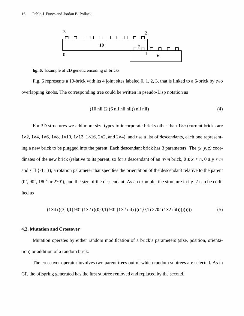
fig. 6. Example of 2D genetic encoding of bricks
Fig. 6 represents a 10-brick with its 4 joint sites labeled 0, 1, 2, 3, that is linked to a 6-brick by two
overlapping knobs. The corresponding tree could be written in pseudo-Lisp notation as
(10 nil (2 (6 nil nil nil)) nil nil) (4)
For 3D structures we add more size types to incorporate bricks other than 1×n (current bricks are
1×2, 1×4, 1×6, 1×8, 1×10, 1×12, 1×16, 2×2, and 2×4), and use a list of descendants, each one represent-
ing a new brick to be plugged into the parent. Each descendant brick has 3 parameters: The(x, y, z)coor-
dinates of the new brick (relative to its parent, so for a descendant of ann×m brick, 0≤ x < n, 0 ≤ y < m
andz ∈ {-1,1}); a rotation parameter that specifies the orientation of the descendant relative to the parent
(0˚, 90˚, 180˚ or 270˚), and the size of the descendant. As an example, the structure in fig. 7 can be codi-
fied as
(1×4 (((3,0,1) 90˚ (1×2 (((0,0,1) 90˚ (1×2 nil) (((1,0,1) 270˚ (1×2 nil))))))))) (5)
4.2. Mutation and Crossover
Mutation operates by either random modification of a brick’s parameters (size, position, orienta-
tion) or addition of a random brick.
The crossover operator involves two parent trees out of which random subtrees are selected. As in
GP, the offspring generated has the first subtree removed and replaced by the second.
10
60 1
23
2

Evolutionary Body Building 17
After mutation or crossover operators are applied, a new, possibly invalid specification tree is
obtained. The result is expanded one node at a time and overlapping is checked. Whenever an overlap is
found the tree is pruned at that site. With this procedure, a maximum spatially valid subtree is built from
a crossover or mutation. Branches that could not be expanded are discarded.
The following mutation of (5), for example, is illegal because two bricks would share the same
physical space (z = -1 after the second brick means that the third one goes below it, but the first brick is
already there).
(1×4 (((3,0,1) 90˚ (1×2 (((0,0,-1) 90˚ (1×2 nil)) (((1,0,1) 270˚ (1×2 nil)))))))) (6)
The tree will be pruned then at the site, yielding just three bricks
(1×4 (((3,0,1) 90˚ (1×2 (((1,0,1) 270˚ (1×2 nil))))))) (7)
Once a valid tree has been obtained, the physical model is constructed and the structure tested for
stress stability. Fitness is evaluated and the new individual is added to the population.
01
23
45 0
12
0.5
1
1.5
2
2.5
fig. 7.Model and tree representation for a few Lego bricks, from eq. 5.
(0,0,1) 90° 1x2 (0,0,1) 270° 1x2
1x4
(3,0,1) 90° 1x2

18 Pablo J. Funes and Jordan B. Pollack
4.3. Evolutionary Algorithm
We use a straightforward steady-state genetic algorithm, initialized with a population of one single
brick. Through mutation and crossover, a population of 1000 individuals is generated and then evolved:
1. While maximum fitness < Target fitness
2. Do Randomly select mutation or crossover.
3. Select 1 (for mutation) or 2 (for crossover) random individual(s) with fitness
proportional probability.
4. Apply mutation or crossover operator
5. Generate physical model and test for gravitational load
6. If the new model will support its own weight
7. Then replace a random individual with it (chosen with inverse fitness pro-portional probability).
5. Results
5.1. Evolving two-dimensional Lego structures
Reaching a target point: Bridges and Scaffolds
In our first experiments we conceived a Lego plate affixed to a table (fig. 8) and evolved 2D struc-
tures to reach a target point, using as fitness function a normalized distance to the target point,
(8)
(whereS is the structure,T the target point andd the euclidean distance).
With a target pointT located horizontally and away from the plate we generated a ‘Lego Bridge’
(figs. 2 and 9), movingT to a remote position we obtained the ‘long bridge’ (fig 10), and puttingT below
we generated a descending structure, a ‘scaffold’ (fig 11).
Nd S T,( ) 1 d S T,( )d 0 T,( )-------------------–=

Evolutionary Body Building 19
External Loads: Horizontal crane arm
With a two-step fitness function that gives one point for reaching a target point as in (8) and, if
reached, additional points for supporting an external weight hanging from the last brick, we evolved a
crane arm as in fig. 12.
Lego plate
Table
EVOLVEDSTRUCTURE
target point
fig. 8.Basic setup: The structure starts on a Lego plate affixed to a table and has to reach a target pointsupporting its own weight.
fig. 9. The ‘Lego bridge’ defined by the scheme of fig. 2, built on our lab table.

20 Pablo J. Funes and Jordan B. Pollack
Since our algorithm gives a yes/no answer for the stability of a structure, we add the weight in small
increments and test repeatedly to create a fitness function in this case. For example, for a target loadm we
can use the following fitness function
1. For i=1 to 100
2. Add a weight m/100 to the structure at T
3. If the structure does not resist, return (i-1)/100
4. return 1.0
fig. 10.Long Bridge
fig. 11.Scaffold.

Evolutionary Body Building 21
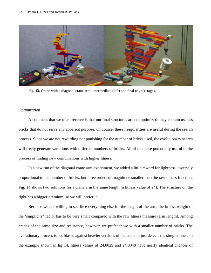
Constraining the space: Diagonal crane arm
For a different type of crane we constrained the space where bricks can be located to the diagonal
subspace {-x<y} only. In order to evolve a crane arm that would support a weight of 250g we wrote a fit-
ness function whose value would be the fraction of 250g supported times the length of the arm along the
x axis. Since no bricks can be placed below the diagonal, the resulting arm goes diagonally up and away
(fig. 13).
In an intermediate generation, we observe a “convergent” evolution of a counterbalancing structure
(also found in the bridge examples). But later in the same run, the configuration touched down, forming a
triangle which afforded a stronger structure. These observed features, the counterbalance and triangle,
which are recognizable by humans as “design elements” are simply emergent higher level phenomena
which are discovered and exploited by evolution inside this physics simulator, much as the nonlinear cir-
cuitry was exploited in evolutionary hardware [38].
fig. 12.Crane with evolved horizontal crane arm.
22 Pablo J. Funes and Jordan B. Pollack
Optimization
A comment that we often receive is that our final structures are not optimized: they contain useless
bricks that do not serve any apparent purpose. Of course, these irregularities are useful during the search
process. Since we are not rewarding nor punishing for the number of bricks used, the evolutionary search
will freely generate variations with different numbers of bricks. All of them are potentially useful in the
process of finding new combinations with higher fitness.
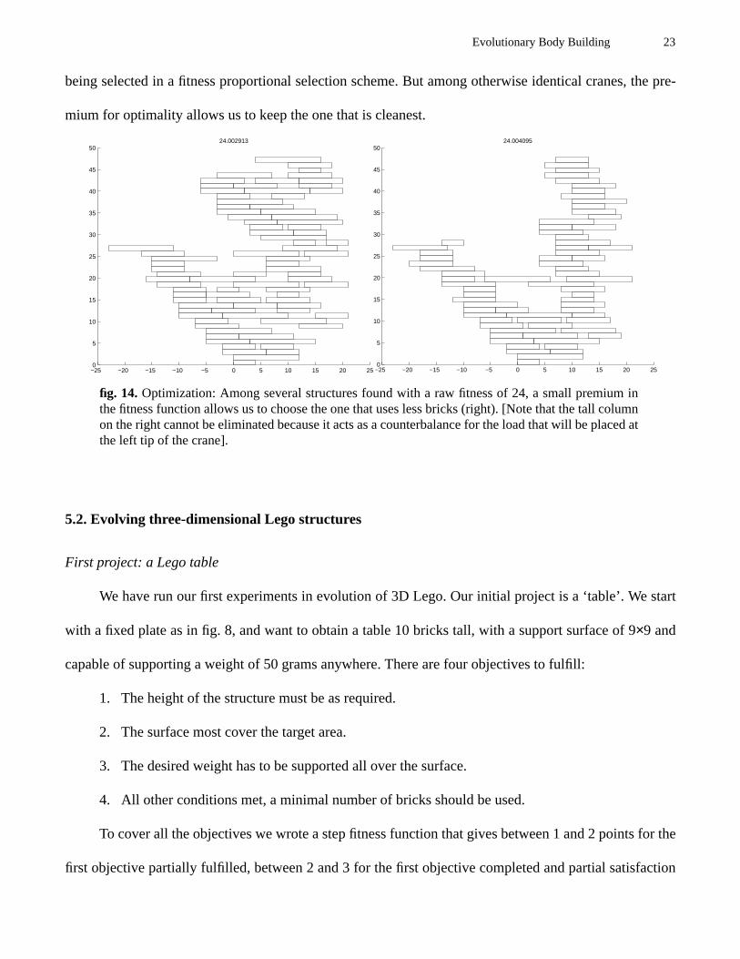
In a new run of the diagonal crane arm experiment, we added a little reward for lightness, inversely
proportional to the number of bricks, but three orders of magnitude smaller than the raw fitness function.
Fig. 14 shows two solutions for a crane arm the same length (a fitness value of 24). The structure on the
right has a bigger premium, so we will prefer it.
Because we are willing to sacrifice everything else for the length of the arm, the fitness weight of
the ‘simplicity’ factor has to be very small compared with the raw fitness measure (arm length). Among
cranes of the same size and resistance, however, we prefer those with a smaller number of bricks. The
evolutionary process is not biased against heavier versions of the crane; it just detects the simpler ones. In
the example shown in fig 14, fitness values of 24.0029 and 24.0040 have nearly identical chances of
fig. 13.Crane with a diagonal crane arm: intermediate (left) and final (right) stages.
Evolutionary Body Building 23
being selected in a fitness proportional selection scheme. But among otherwise identical cranes, the pre-
mium for optimality allows us to keep the one that is cleanest.
5.2. Evolving three-dimensional Lego structures
First project: a Lego table
We have run our first experiments in evolution of 3D Lego. Our initial project is a ‘table’. We start
with a fixed plate as in fig. 8, and want to obtain a table 10 bricks tall, with a support surface of 9×9 and
capable of supporting a weight of 50 grams anywhere. There are four objectives to fulfill:
1. The height of the structure must be as required.
2. The surface most cover the target area.
3. The desired weight has to be supported all over the surface.
4. All other conditions met, a minimal number of bricks should be used.
To cover all the objectives we wrote a step fitness function that gives between 1 and 2 points for the
first objective partially fulfilled, between 2 and 3 for the first objective completed and partial satisfaction
−25 −20 −15 −10 −5 0 5 10 15 20 250
5
10
15
20
25
30
35
40
45
5024.002913
−25 −20 −15 −10 −5 0 5 10 15 20 250
5
10
15
20
25
30
35
40
45
5024.004095
fig. 14.Optimization: Among several structures found with a raw fitness of 24, a small premium inthe fitness function allows us to choose the one that uses less bricks (right). [Note that the tall columnon the right cannot be eliminated because it acts as a counterbalance for the load that will be placed atthe left tip of the crane].

24 Pablo J. Funes and Jordan B. Pollack
of the second, and so on. With this setup, the algorithm builds upward first, then broadens to cover the
surface, later secures that all points of the surface support a load of 50g and finally tries to reduce the
number of bricks to a minimum.
One of the solutions we obtained is shown in figs. 4 and 5, and a picture of the Lego table built in
fig. 15.
Problems defining the fitness function
A first attempt to evolve a table failed to satisfy objective 2 (covering the entire surface). The rea-
sons for this failure require further investigation. One problem with our representation is that the distance
between genotype and phenotype is big: most mutations are too radical. Also, not having 1×1 bricks com-
plicates matters (our current set of Lego does not include those). Finally, there is little selective pressure
as fitness values between 1.9 and 2.0 are nearly identically selected. The raw value in the range [1, 5] was
expanded by an exponential function to add selective pressure (so for example the fitness value of 123.74
fig. 15.Lego table as specified by the diagram of fig. 4, holding a 50g weight.

Evolutionary Body Building 25
in fig. 4 corresponds to a raw fitness of 4.8), but this did not solve the problem of full coverage. For the
successful run pictured above the coverage objective was redefined as ‘covering at least 96% of the target
area’.
The use of stepped fitness functions might not be ideal; Pareto optimality aware GA techniques [18,
ch. 5] should improve performance in multiobjective problems such as this one.
6. Discussion and future research directions
With a model based on one simple, intuitive principle — maximum torque — we obtained a fast
and cheap way to simulate a variety of brick structures. One line of future work deals with extensions to
this simulator. On one hand, the greedy algorithm is not a universal solution for the equations of the
model, and further study should reveal more efficient techniques for this particular problem. On the other,
extensions to cover more physical features, dynamics to begin with, will open the door to evolving mov-
ing robots for real-world environments.
6.1. Limitations of modelling
The properties of bricks are variable. Differences in construction, age, dirt, temperature, humidity
and other unpredictable factors produce seemingly random variations when their behavior is measured.
These factors had to be considered in order to have buildable results. As mentioned, we have accounted
for this problem using a ‘safety margin’ of 20%. This means that our model actually assigns 20% less
resistance to all the joints involved. Any model for modular structures will have to incorporate safety
margins to compensate for the random variability of the generic properties of the average brick, but the
value of 20% was set intuitively and may require further study, especially as our structures scale up in
size and complexity.

26 Pablo J. Funes and Jordan B. Pollack
Engineers have known for a long time the need for safety margins. Evolutionary roboticists have
found similar unpredictabilities when attempting to simulate the environment for a real robot [24, 30].
This has led to the incorporation of random noise in the simulators in order to generate robust behaviors
suitable to be transferred to the real world. Noise and safety margins are fundamental principles for simu-
lation because they allow the evolution of robust, buildable mechanisms.
6.2. Modular and Reconfigurable Robotics
Different groups are studying the idea of modifiable robots, built from one or a few types of ele-
mentary modules and — sometimes — with the ability to dynamically reconfigure themselves [14, 40,
32, 6]. Chirikjian’s group, for example, is aiming at developing cellular ‘metamorphic’ robots that actuate
by reshaping and displacing its robotic units [32]. As mechatronics advance, we believe it will be possible
to combine cellular robotics components with corresponding simulators to produce complex, evolution-
ary adapted robots.
6.3. Movement Planning as Evolution?
Evolutionary algorithms solve a problem by maintaining a population of variant partial solutions
and applying recombination operators to them. Those operators can be considered valid, or available
operations in a space of configurations. Our brick structures algorithms are solving problems of spatial
arrangement, subject to buildability restrictions, starting from a known initial configuration and advanc-
ing, one step at a time, by legal transformations. The simulation enforces that each step is physically cor-
rect.
The implication is that the succession of genetic transformations that yield to a final stage can be
considered a plan. Problems of planning for spatial arrangement are classic in AI [11]. One plausible
future application of structural evolutionary algorithms is to adapt the recombination operations to reflect
Evolutionary Body Building 27
valid reconfigurations of a modular metamorphic robot. Problems of robot locomotion for example could
be solved by evolving a plan for the desired final configuration from the starting one.
6.4. Cellular and Modularity-Sensitive Representations
The problem of neural network representations for evolution of recurrent networks is similar to our
problem of encoding brick structures. From early naive representations the concept of ‘developmental’ or
‘cellular’ grammatical encodings emerged [2, 25, 19]. They increase the efficiency of the GA by reducing
the search space, eliminating redundancies and meaningless codes, and providing meaningful recombina-
tion operators.
We think that such advanced representation techniques have to be adapted to evolution of modular
structures in order to empower the GA with topological encodings that translate the genetic space
smoothly into the space of virtual objects.
There have been studies of modularity in recurrent neural net representations [20, 1], aiming to
improve the GA with automatic creation of libraries of reusable subcomponents. Structural representa-
tions should ultimately aim at the same objective: Finding useful complex blocks and incorporating them
in the making of large structures with inherent modularities.
Finally, more advanced GA techniques such as multiobjective optimization, speciation, automatic
functional decomposition or landscape models [18, 10], may improve over the performance of our basic
steady-state GA.
7. Conclusions
In machine learning and artificial evolution systems, the more interesting results, such as Sims’
creatures or expert backgammon players, are due more to elements of the learning environment than to

28 Pablo J. Funes and Jordan B. Pollack
any sophistication in the learning algorithm itself [37, 33]. By keeping inductive biases andad hocingre-
dients to a minimum, we have demonstrated that interesting real-world behavior can come from a simple
virtual model of physics and a basic adaptive algorithm.
We have shown that the use of modular building elements with predictable — within an error mar-
gin — properties allows evolutionary algorithms to manipulate physical entities in simulation in ways
similar to what we have seen, for example, in the case of robot control architectures. The bits in artificial
chromosomes are capable of representing the building blocks of complete modular structures.
Our results demonstrate that a simulator for the physics of modular objects can be used in an evolu-
tionary computation, and then the objects can be built. This is different from evolving controllers for
existing hardware. Many traditional robot engineering projects view the construction of a physical plant,
like an articulated humanoid body, to be the key achievement, leaving the “coding” to mere programmers
as an afterthought. In nature, the brain for a body and the body for a brain are exquisitely intertwined and
co-adapted. Our work is a step along the way to the full co-evolution of morphology and behavior we
believe is necessary for the development of robots and brains with higher complexity than humans can
engineer.
8. References
[1] Angeline, P. J. & Pollack, J. B. (1994). Coevolving High-Level Representations. In C. Langton (ed.)Artificial
life III. Addison-Wesley, Reading, Mass. pp. 55-71.
[2] Belew, R. K., McInerney, J. and Schraudolf, N. (1990) Evolving Networks, Using the Genetic Algorithm
with Connectionist Learning. Technical Report CSE-CS-174, UCSD.
[3] Bentley, P. J. (1996)Generic Evolutionary Design of Solid Objects using a Genetic Algorithm.Ph.D. thesis,
Division of Computing and Control Systems, School of Engineering, The University of Huddersfield.
[4] Brooks, R. A. (1990) Elephants Don’t Play Chess, inRobotics and Autonomous Systems6, 3-15.

Evolutionary Body Building 29
[5] Chapman, C. D., Saitou, K. and Jakiela, M. J. (1993) Genetic Algorithms as an Approach to Configuration
and Topology Design, in Gilmore, B. (ed)Advances in design automation, 1993. American Society of
Mechanical Engineers (ASME), series DE, vol 65:1. New York. pp. 485-498.
[6] Chen, I. and Burdick J.W. (1993). Enumerating the Non-Isomorphic Assembly Configurations of Modular
Robotic Systems. InProceedings of the 1993 IEEE/RSJ International Conference on Intelligent Robots and
Systems: Intelligent Robots for Flexibility. Institute of Electrical and Electronics Engineers. New York. pp.
1985-1992.
[7] Cliff, D., Husbands, P.and Harvey, I. (1992) Analysis of Evolved Sensory-Motor Controllers. Technical
Report CSRP 264, University of Sussex School of Cognitive and Computing Sciences.
[8] Cliff, D. and Noble, J. (1997) Knowledge-Based Vision and Simple Visual Machines.Philosophical Transac-
tions of the Royal Society of London: Series B 352. pp. 1165-1175
[9] Cormen, T. H., Leiserson, C. E. and Rivest, R. L. (1989). Introduction to Algorithms. MIT press - McGraw
Hill, Cambridge Mass - London.
[10] Darwen, P. J. (1996)Co-evolutionary Learning by Automatic Modularisation with Speciation. Ph.D. Thesis,
University of New South Wales, 1996.
[11] Fahlman, S. E. (1974) A Planning System for Robot Construction Tasks.Artificial Intelligence 5. pp. 1-49.
[12] Floreano, D. and Mondada, F. (1996). Evolution of Homing Navigation in a Real Mobile Robot.IEEE Trans-
actions on Systems, Man, and Cybernetics--Part B: Cybernetics, 26(3), 396-407.
[13] Forbus, K. (1984). Qualitative process theory. InArtificial Intelligence 24, 85-168.
[14] Fukuda, T. and Kawauchi, Y. (1990) Cellular Robotic System (CEBOT) as One of the Realization of Self-
organizing Intelligent Universal Manipulator. InProceedings of the 1990 IEEE International Conference on
Robotics and Automation.IEEE Computer Society Press, Los Alamitos, Calif. pp. 662-667.
[15] Funes, P. and Pollack, J. (1998). Componential Structural Simulator. Brandeis University Computer Science
Technical Report CS-98-198.
[16] Funes, P. and Pollack, J. (1997). Computer Evolution of Buildable Objects.Fourth European Conference on
Artificial Life. P. Husbands and I. Harvey, eds., MIT Press. pp 358-367.
[17] Gardin, F. and Meltzer, B. (1989). Analogical Representations of Naive Physics.Artificial Intelligcence38,
pp 139-159.

30 Pablo J. Funes and Jordan B. Pollack
[18] Goldberg, David E. (1989).Genetic Algorithms in Search, Optimization, and Machine Learning.Addison-
Wesley.
[19] Gruau, F. (1992) Cellular Encoding of Genetic Neural Networks. Technical Report 92.21, Laboratoire de
l’Informatique du Parallélisme, Ecole Normale Supérieure de Lyon.
[20] Gruau, F. (1993) Genetic Synthesis of Modular Neural Networks. In Forrest, S. (ed.)Proceedings of the Fifth
International Conference on Genetic Algorithms, Morgan-Kaufman, San Mateo, Calif. pp 318-325.
[21] Hornby, G. and Pollack, J. (1998) Personal Communication.
[22] Iusem, A. and Zenios, S. (1995). Interval Underrelaxed Bregman’s method with an application. InOptimiza-
tion, vol. 35, iss. 3, p. 227.
[23] Jakobi, N. (1997) Half-baked, Ad-hoc and Noisy: Minimal Simulations for Evolutionary Robotics. InFourth
European Conference on Artificial Life. P. Husbands and I. Harvey, eds., MIT Press. pp 348-357
[24] Jakobi, N., Husbands, P. and Harvey, I. (1995). Noise and the Reality Gap: The use of Simulation in Evolu-
tionary Robotics, inAdvances in Artificial Life: Proceedings of the 3rd European Conference on Artificial
Life, Moran, F., Moreno, A., Merelo, J., Chacon, P. (eds.) Springer-Verlag, Lecture Notes in Artificial Intelli-
gence 929. Berlin - New York. pp. 704-720.
[25] Kitano, H. (1990) Designing Neural Network Using Genetic Algorithm with Graph Generation System.
Complex Systems 4. pp. 461-476.
[26] Koza, John R. (1992). Genetic Programming: On the Programming of Computers by Means of Natural
Selection. Cambridge, MA: The MIT Press.
[27] Lee, W., Hallam, J. and Lund, H. (1996). A Hybrid GP/GA Approach for Co-evolving Controllers and Robot
Bodies to Achieve Fitness-Specified Tasks. InProceedings of IEEE 3rd International Conference on Evolu-
tionary Computation. IEEE Press, Piscataway, N.J. pp. 384-389.
[28] Leighton, T., Makedon, F., Plotkin, S., Stein, C., Tardos, E. and Tragoudas, S. (1995). Fast Approximation
Algorithms for Muticommodity Flow Problems.Journal of Computer and System Sciences 50. p. 228-243.
[29] Lund, H., Hallam, J and Lee, W. (1997). Evolving Robot Morphology. Invited paper inProceedings of IEEE
Fourth International Conference on Evolutionary Computation.IEEE Press, Piscataway NJ. pp 197-202.
[30] Mataric, M and Cliff, D. (1996). Challenges In Evolving Controllers for Physical Robots. InEvolutionary
Robotics, special issue ofRobotics and Autonomous Systems, Vol. 19, No. 1. 67-83.

Evolutionary Body Building 31
[31] Ngo, J.T., and Marks, J. (1993). Spacetime Constraints Revisited. In Kajiya, J. (ed.)Computer Graphics,
Annual Conference Series 93. Association for Computing Machinery (ACM), New York. p. 335-342.
[32] Pamecha, A., Chiang, C, Stein, D. and Chirikjian, G. S. (1996). Design and Implementation of Metamorphic
Robots. In McCarthy, J. (ed.)Proceedings of the 1996 ASME Design Engineering Technical Conference and
Computers in Engineering Conference (Published as CD). ASME.
[33] Pollack, J. B., Blair, A. D. (1998). Coevolution in the successful learning of backgammon strategy.Machine
Learning 32, pp. 225-240.
[34] Schoenauer, M. (1996). Shape Representations and Evolution Schemes. In L. J. Fogel, P. J. Angeline and T.
Back, Editors,Proceedings of the 5th Annual Conference on Evolutionary Programming, MIT Press, Cam-
bridge Mass. 121-129.
[35] Sims, K. (1994) Evolving Virtual Creatures. In Glassner, A., et al. (eds.)Computer Graphics, Annual Confer-
ence Series 94. Association for Computing Machinery (ACM), New York. pp 15-22.
[36] Sims, K. (1994) Evolving 3D Morphology and Behavior by Competition. In Brooks, R and Maes, P. (eds.)
Artificial Life IV, MIT Press, Cambridge, Mass. pp 28-39.
[37] Tesauro, G. (1995) Temporal difference learning and TD-Gammon.Communications of the ACM,38(3): 58-
68.
[38] Thompson, A. (1995). Evolving electronic robot controllers that exploit hardware resources. In Moran, F
(ed.) Proceedings of the 3rd European Conference on Artificial Life (ECAL’95), Springer-Verlag Lecture
Notes in Artificial Intelligence 929, Berlin - New York. pp. 640-656.
[39] Webb, B. (1995). Using robots to model animals: a cricket test.Robotics and Autonomous Systems 16. pp.
117-134.
[40] Yim, M. (1995). Locomotion With A Unit-Modular Reconfigurable Robot. Thesis, Stanford University,
Department of Computer Science.
[41] Zienkiewicz, O.C.The Finite Element Method in Engineering Science.McGraw-Hill, New York, 3rd edition,
1977.