evolution zoom - seiler medical · iec 60601-1, 1988 medical electrical equipment, part 1: general...
TRANSCRIPT

Evolution ZoomMultidisciplinary Operating Microscope
User’s Manual
This document is property of Seiler Instrument & Mfg. Co., Inc. No part of this manual should be reproduced or transmitted without the expressed written consent being obtained. All the figures appearing in this manual are for illustration purposed only and may vary according to the version of the device purchased. The information contained in this manual is subject to change without notice. Please contact Seiler whenever additional information is needed. This device is restricted to the sale and the use by authorized and trained personnel.
NEUROSURGERY, SPINE, ENT, AND PLASTIC

2 Seiler Evolution Zoom Microscope
I. INTRODUCTION 4
II. DECLARATION OF CONFORMITY 5
III. CONFORMITY 6DESIGN STANDARDS ����������������������������������������������������������������������������������������������������������������� 6SAFETY GUIDELINES ����������������������������������������������������������������������������������������������������������������� 6
IV. PARTS AND COMPONENTS 8
V. INSTALLING THE EQUIPMENT 11UNPACKING �����������������������������������������������������������������������������������������������������������������������������11INSTALLATION LOCATION ��������������������������������������������������������������������������������������������������������12USING TRANSFORMERS �����������������������������������������������������������������������������������������������������������12ELECTRIC CONNECTIONS ���������������������������������������������������������������������������������������������������������13
VI. USING THE MICROSCOPE 15SWITCHING ON THE UNIT ��������������������������������������������������������������������������������������������������������17ADJUSTING DIOPTER ���������������������������������������������������������������������������������������������������������������18ADJUSTING INTERPUPILLARY DISTANCE �����������������������������������������������������������������������������������18ADJUSTING MAGNIFICATION ����������������������������������������������������������������������������������������������������18ADJUSTING FOCUS ������������������������������������������������������������������������������������������������������������������18ADJUSTING LIGHT LEVEL ���������������������������������������������������������������������������������������������������������19USING THE XY SYSTEM (OPTIONAL) �����������������������������������������������������������������������������������������19USING THE INCLINABLE BINOCULAR HEAD 19ULTRAVIOLET (UV) FILTER �������������������������������������������������������������������������������������������������������19
VII. MAINTENANCE AND HYGIENE 20 SWITCHING BULBS DURING USE (ONLY FOR UNITS WITH HALOGEN BULB) 20 REPLACING A BURNT OUT BULB (ONLY FOR UNITS WITH HALOGEN BULB) 20 LED RELIABILITY AND LIFETIME (ONLY FOR UNITS WITH LED SOURCE) 21REPLACING A BLOWN FUSE ������������������������������������������������������������������������������������������������������21REPAIRING THE EQUIPMENT ����������������������������������������������������������������������������������������������������21CLEANING �������������������������������������������������������������������������������������������������������������������������������22
VIII. ACCESSORIES 23IMAGE SPLITTER ����������������������������������������������������������������������������������������������������������������������24VIDEO CAMERA �����������������������������������������������������������������������������������������������������������������������24
Table of Contents

3 Seiler Evolution Zoom Microscope
VIDEO CAMERA ADAPTER �������������������������������������������������������������������������������������������������������������� 24 DIGITAL PHOTOGRAPHIC CAMERA ADAPTER 24SECOND OBSERVER ACCESSORY ��������������������������������������������������������������������������������������������������� 24IMAGE INVERTER �������������������������������������������������������������������������������������������������������������������������� 24MULTIFUNCTION PEDAL ���������������������������������������������������������������������������������������������������������������� 24FIXED BINOCULAR HEAD (45º) ������������������������������������������������������������������������������������������������������ 24ZOOM SYSTEM ������������������������������������������������������������������������������������������������������������������������������ 24FILTERS���������������������������������������������������������������������������������������������������������������������������������������� 25
IX. MECHANICAL DATA 25MECHANICAL DATA ���������������������������������������������������������������������������������������������������������������������� 25ELECTRICAL DATA ������������������������������������������������������������������������������������������������������������������������� 25OPTICAL DATA ������������������������������������������������������������������������������������������������������������������������������ 26
X. TRANSPORTATION, STORAGE AND ENVIRONMENTAL CONDITIONS 27
XI. DISCARD 27
XII. TROUBLESHOOTING 28
XIII. SYMBOLS 29
XIV. WARNING 30
XV. TERM OF WARRANTY 30
XVI. CONTACT INFORMATION 30
XVII. OWNERS RECORD 31
XVIII. NOTES 31
XIX. CERTIFICATES OF COMPLIANCE 32-33
XX. WARRANTIES 34-35

4 Seiler Evolution Zoom Microscope
I. IntroductionDear customer,
The Seiler Evolution Zoom Microscope you have acquired is a modern, reliable device, which has been designed using the most advanced optical design tools available on the market. In addition, its optical superiority allows obtaining refined image quality.
This equipment contains ergonomic characteristics and can be easily handled by the users�
This equipment is intended to be used exclusively for amplifying the image observed, so as to provide the user with excellent level of comfort and improved visual acuity during the activities�
It is NOT specified for use in any measurement work.
Using this microscope as support equipment does NOT remove the need for professional skill�
The equipment uses halogen bulbs or Light-Emitting Diode (LED) source to produce visible light for illuminating the visual field.
The Seiler Evolution Zoom Microscope is manufactured according to stringent standards, and the use of precision mechanics and quality optics in order to ensure high-quality final product.
All optical components have undergone anti-reflective multi-layer treatment, which ensures the efficiency of the system across the entire visible spectrum.
In case of further information or queries about this equipment, its parts or accessories, please contact us immediately at the contact information below�
Our team is always ready to provide assistance to the customers whenever necessary�
Specific technical data about this microscope can be requested from:
Seiler Instrument & Manufacturing Co., Inc.Medical Division
Toll-Free: 800-489-2282Local: 314-968-2282Fax: 314-968-3601
E-mail: [email protected]�seilerinst�com

5 Seiler Evolution Zoom Microscope
II. Declaration of conformityThe Seiler Evolution Zoom Microscope bears the CE standard as set out below:
DECLARATION OF CONFORMITYWe hereby declare that the product:
Seiler Evolution Zoom MicroscopeIt is a Class I device, bearing the CE1 mark of quality, produced in compliance with the 93/42EEC (MDD) guidelines, pursuant to the Risk Classification (MDD, appendix IX)� this device also complies with the requirements set out in Appendices I and VII of the aforesaid guidelines, including the basic requirements�
This product has been developed in due accordance with the applicable requirements of the following Standards:
IEC 60601-1, 1988 Medical Electrical Equipment, Part 1: General Requirements for Safety
IEC 60601-1-2, 2001 Medical Electrical Equipment, Part 1: General Requirements for Safety
and 2. Electromagnetic Compatibility The following Standard is used for Risk Analysis and selecting the applicable
requirements:
BS EN 1441:1997 Medical Devices - Risk Analysis
This Declaration embraces all Seiler Evolution Zoom Microscope products manufactured in according with the Technical Product Report2
Indication: Seiler Evolution Zoom Microscope is an electric device which runs on an AC power source� This device shall be used to magnify the image observed during surgical and other medical procedures� It does NOT possess any measurement devices or functions and sterilization prior to the use is NOT required� This device does NOT make use of any chemical or pharmacological substances�
Self-certification and Declaration of Conformity are the only requirements (Appendices I, II, VII of the MDD).2 Available from the authorized representative in Europe�

6 Seiler Evolution Zoom Microscope
III. ConformitySeiler Instrument has developed this device in due accordance with global quality requirements, giving priority to safety, electromagnetic compatibility and failure management, thereby establishing the Seiler Evolution Zoom Microscope as a highly safe, reliable and robust device� The main quality standards employed were based upon the standards set out below:
3.1 Design StandardsIEC 60601-1:1988 - Medical Electrical Equipment, Part 1 - General Requirements for SafetyEN IEC 60601-1-2:2001 Medical Devices - EMC RequirementsEN 55011:1991- Radiated and Conducted Emission (Class 1, Group A)IEC 61000-4-2: 1995 (Electrostatic Discharge)IEC 801-3:1984 (Radiated Electromagnetic Field)IEC 61000-4-4:1995 (Electrical Fast Transient / Burst)IEC 61000-4-5:1995 (Electrical Surge)CISPR 14 (Click)BS EN 1441: 1998 (Risk Analysis)
3.2 Safety GuidelinesThe Seiler Evolution Zoom Microscope is a class 1 low risk device – in accordance with FDA (Federal Drug Association EE UU) 21CFR, European Directive 93/42/EEC on medical devices and ANVISA-PC1, 26/01/1996 (Brazilian Certification Rules). Nevertheless, we recommend that the following guidelines be followed:
• Before turning ON and using the device, follow the instructions set forth on the labels and carefully read the present User’s guide�
• This device IS NOT SUITABLE FOR USE IN THE PRESENCE OF INFLAMMABLE MIXTURES CONTAINING AIR, OXYGEN OR NITROUS OXIDE�
• This device is NOT to be used in home�
• This device must always be used correctly (Chapter 2)�
• Correctly check the output power level (visible light)� Use the visible light output with caution - this could damage the patient’s eyes if there is prolonged, improper exposure to the eyes�
• Ensure the appropriate protection is used during each procedure�
• Check the availability of a spare bulb for use before embarking upon any procedure� Burned out bulb should only be replaced after checking if the device is switched off and has cooled down�
• Connect the device to a no break device using high-quality batteries, for which a minimum power of 1000W (semi-sinusoidal) has been properly calibrated� If this is NOT done, the device may NOT support the high voltage�
• Take care when handling the Fiber Optic Cable (for halogen bulb microscope)� It is made up of extremely fine, very sensitive fibers. Improper use can break these fibers affecting the performance of the Cable�
• Please contact Seiler Instrument if any special filter is required.

7 Seiler Evolution Zoom Microscope
• Manufacturing
• Designed and manufactured pursuant to the Harmonized European EN Standards numbers 60601-1:1990, 60601-1-2:2007, 60601-1-4:1996. The product also meets the requirements of the NBR and IEC standards� More details can be requested to Seiler Instrument (www�seilermicro�com)�
• Equipment with Class 1, Type B protection degree� Short-duration operation� Degree of Risk IIb, pursuant to MDD 93/42, of the European Union, and Degree of Risk III, pursuant to ANVISA Resolution 185, Brazil�
PLEASE NOTE: The device has been designed to meet all mandatory standards related to this type of product and all the guidelines stated herein must be considered.

8 Seiler Evolution Zoom Microscope
IV. Parts and ComponentsThe Seiler Evolution Zoom Microscope is divided into modules (Figure 1)�
Figure 1: Modules of the Seiler Evolution Zoom Microscope
MODULE FUNCTIONS AND FEATURESColumn The column provides mechanical support to the equipment�Control Box The control box contains the electronic circuits for the microfocusing, illumination
brightness control, zoom and XY system functions of the microscope�Illumination Box Light is generated by the illumination box�
For microscopes with halogen bulb source, the light is supplied to the working area by means of an optical fiber cable to the microscope’s optical module.
The equipment is also available with LED source� Pantographic Arm
The pantographic arm is the structural module between the illumination box and the optical module�
Optical Module The optical module comprises the objective lens, continuous magnification system (zoom), and the binocular head�
A joystick is used for adjusting zoom, light level and focus multifunctional pedal�Multifunctional Pedal
The multifunctional pedal controls microfocus, on-off illumination, illumination brightness, XY system and zoom (if applicable)�
9 Seiler Evolution Zoom Microscope
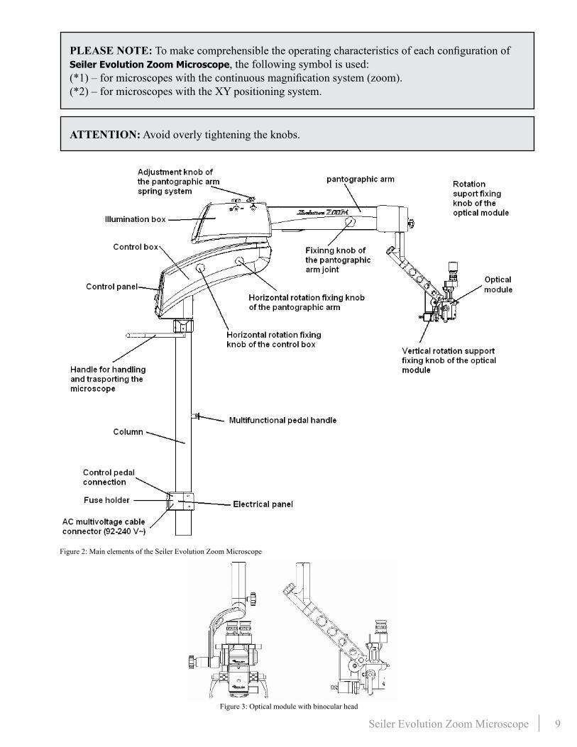
PLEASE NOTE: To make comprehensible the operating characteristics of each configuration of Seiler Evolution Zoom Microscope, the following symbol is used:(*1) – for microscopes with the continuous magnification system (zoom).(*2) – for microscopes with the XY positioning system.
ATTENTION: Avoid overly tightening the knobs.
Figure 2: Main elements of the Seiler Evolution Zoom Microscope
Figure 3: Optical module with binocular head

10 Seiler Evolution Zoom Microscope
Figure 4: Multifunctional pedal
Figure 5: Control panel
Figure 6: Joystick for adjusting zoom, light level and focus

11 Seiler Evolution Zoom Microscope
V. Installing the Equipment
PLEASE NOTE: Before any attempt to assemble or install the Seiler Evolution Zoom Microscope, please read carefully and thoroughly the present User’s Guide.The assembly and install activities shall only be performed by authorized technicians.Seiler Instrument shall NOT be liable for any other type of procedure NOT set forth herein used to install or assemble this product, nor shall be liable for any misuse of tools.
5.1 UnpackingThe Seiler Evolution Zoom Microscope is placed into plywood boxes and foams to protect the equipment during transportation and storage�
Check the boxes for damage or signs of violation: please contact Seiler Instrument immediately in the event of any irregularity� The Seiler Evolution Zoom Microscope should ideally be transported into its original packaging, which shall be kept for further use�
Please check whether the box contains the items set out below:
• This User’s Guide
• Base
• Column
• Control box, illumination box and pantographic arm, already assembled
• Screw to fasten the base to the column
• Accessories, if applicable
• AC Multi-voltage cable 90-240V~
• Protective cover for the optical module
• 1 spare halogen bulb (only for Seiler Evolution Zoom Microscope with halogen bulb)
• 2 5A fuses
• Fixing pin for optical module support / XY system (*2), optical fiber (for the microscope with halogen bulb source) and electric cables already installed
• Optical module (discrete or zoom) already connected to its support system
• 1 pair of knobs of the optical module
• 1 pair of autoclave protectors knobs of the optical module
• Multifunctional pedal (*1) and/or (*2)

12 Seiler Evolution Zoom Microscope
PLEASE NOTE: The control box, the illumination box and the pantographic arm must be handled carefully, because the external surfaces of these modules can be easily damaged. A sharp impact on these surfaces may result in scratches or other damages.The optical module is the most delicate part. Take care during use, transportation or handling. It is fitted to a specific support (Figure 3).
PLEASE NOTE: Take care when handling the Fiber optic cable (only applicable to the configuration with halogen bulb source). It is made up of extremely fine, very sensitive fibers. Improper use, repeated stretching and bending movements can cause damages that affect the performance or even rendering it useless.
PLEASE NOTE: The optical module is assembled in a sealed block. Maintenance activities shall only be performed by the AUTHORIZED TECHNICAL ASSISTANCE.
5.2 Installation LocationThe equipment shall be installed and operated indoor�
The following are instructions regarding the device’s installation location:
CAUTION: Spilling or evaporating flammable materials (e.g. cleaning agents) may cause fire or electrical shock when in contact with electrical parts.
CAUTION: Do NOT cover the power supply ventilation openings.
ATTENTION: The selected location should have relative humidity of 55 ± 15 % and ambient temperature of 22 ± 3 °C.
CAUTION: Do NOT install the device: • Near areas where large amounts of water are used. • Where it is exposed to direct sunlight. • In places where ventilation devices and air conditioners blow directly on the device. • In places where heating devices directly affect the equipment. • In unsafe places.• In dusty environments. • In a saline or sulfurous environment.• In areas with high temperature or high humidity. • In a freezing or condensing environment.
5.3 Using TransformersIf it is necessary to use a transformer, it shall be insulated type�
Do NOT use auto-transformers, because they may damage the device and put the user at risk�

13 Seiler Evolution Zoom Microscope
5.4 Electric Connections5.4.1 Electrical Panel/Column ConnectionThe electrical panel cover is fastened to the column with screws (Figure 2)�
The cables shall be connected as indicated (Figure 7)�
5.4.2 Electrical Panel External ConnectionConnect the cables as indicated below:
Connect the Power cable to the AC connector on the electrical panel of the column (Figure 8)� The device can be connected at any level of voltage ranging from 90-240V~, 50/60 Hz (adjusted automatically to properly work in these ranges)�
Make the connection between the multifunctional pedal cable and the electrical panel as indicated (Figure 8)�
Figure 7: Electrical panel connections: internal part of the panel cover (left) and the column (right)
Figure 8: Frontal view of the electrical panel of the column

14 Seiler Evolution Zoom Microscope
5.4.3 Pantographic Arm ConnectionConnect the microfocus / zoom cable to the connector indicated on the pantographic arm (Figure 9)�
Insert the XY connection cable to the XY connector (*2) (Figure 9)�
Connect the video system power cable to its connector, if applicable (Figure 9)�
Figure 9: Lower View of pantographic arm (electrical connection)
ATTENTION: Please take care when connecting cables as the connector pins are fragile.
CAUTION: The grounding terminal must be connected to an active grounding point.Failing to do so may cause electrical shock, damage the device or cause it to NOT operate properly.
PLEASE NOTE: The device is immune to electromagnetic radiation within the limits specified under the EN 60601-1-2 standard and the updated version of IEC 60601-1-2.
15 Seiler Evolution Zoom Microscope
VI. Using the microscope
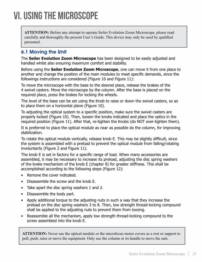
ATTENTION: Before any attempt to operate Seiler Evolution Zoom Microscope, please read carefully and thoroughly the present User’s Guide. This device may only be used by qualified personnel.
6.1 Moving the UnitThe Seiler Evolution Zoom Microscope has been designed to be easily adjusted and handled whilst also ensuring maximum comfort and stability�
Before using the Seiler Evolution Zoom Microscope, one can move it from one place to another and change the position of the main modules to meet specific demands, since the followings instructions are considered (Figure 10 and Figure 11):
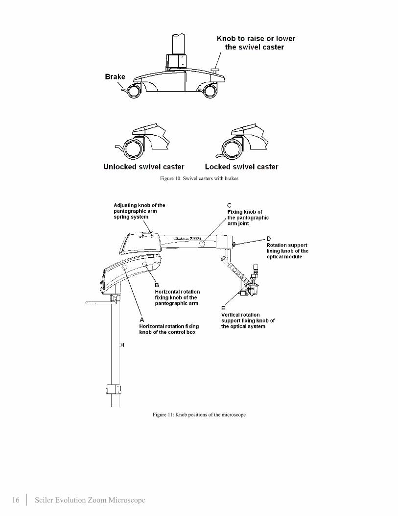
To move the microscope with the base to the desired place, release the brakes of the 4 swivel casters� Move the microscope by the column� After the base is placed on the required place, press the brakes for locking the wheels�
The level of the base can be set using the Knob to raise or down the swivel casters, so as to place them on a horizontal plane (Figure 10)�
To adjusting the optical system to a specific position, make sure the swivel casters are properly locked (Figure 10)� Then, loosen the knobs indicated and place the optics in the required position (Figure 11)� After that, re-tighten the Knobs (do NOT over-tighten them)�
It is preferred to place the optical module as near as possible do the column, for improving stabilization�
To rotate the optical module vertically, release knob E. This may be slightly difficult, since the system is assembled with a preload to prevent the optical module from falling/rotating involuntarily (Figure 2 and Figure 11)�
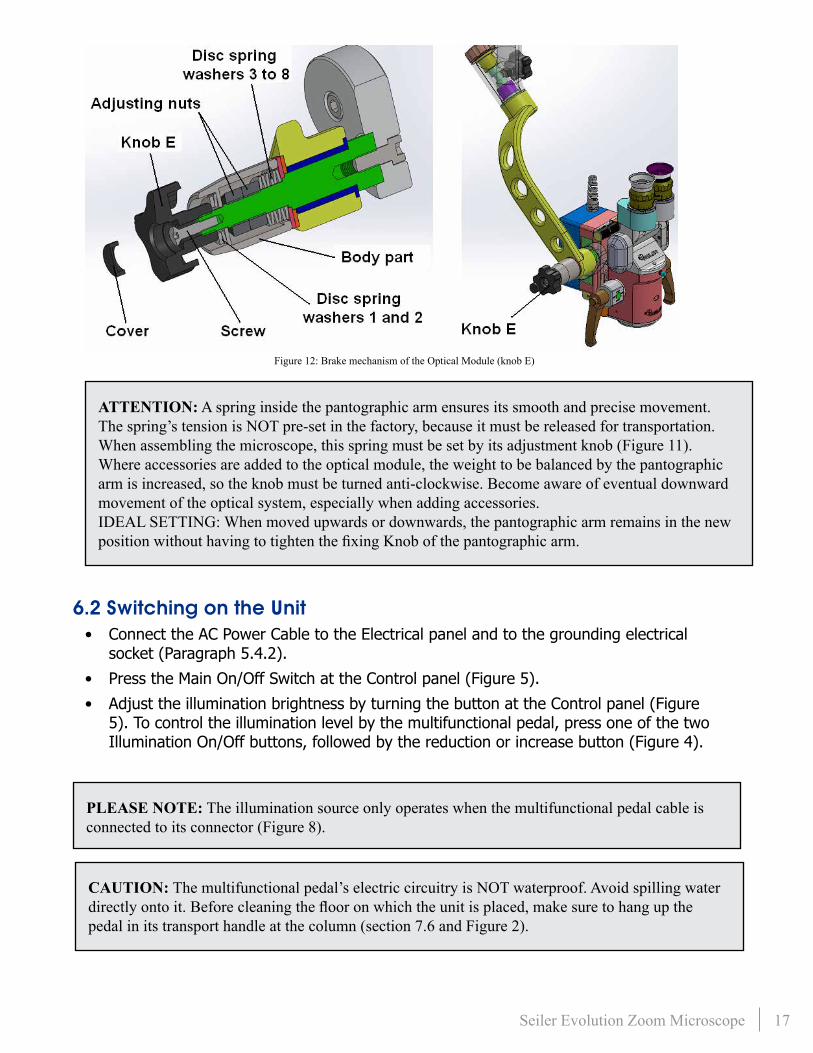
The knob E is set in factory for a specific range of load. When many accessories are assembled, it may be necessary to increase its preload, adjusting the disc spring washers of the brake mechanism of the knob E (chapter 8) for greater stiffness� This shall be accomplished according to the following steps (Figure 12):
• Remove the cover indicated�
• Disassemble the screw and the knob E�
• Take apart the disc spring washers 1 and 2�
• Disassemble the body part�
• Apply additional torque to the adjusting nuts in such a way that they increase the preload on the disc spring washers 3 to 8� Then, low strength thread-locking compound shall be applied to the adjusting nuts to prevent them from loosing�
• Reassemble all the mechanism, apply low strength thread-locking compound to the screw assembled into the knob E�
ATTENTION: Never use the optical module or the microfocus motor covers as a rest or support to pull, push, raise or move the equipment. Only use the column or its handle to move the unit.
16 Seiler Evolution Zoom Microscope
Figure 10: Swivel casters with brakes
Figure 11: Knob positions of the microscope
17 Seiler Evolution Zoom Microscope
Figure 12: Brake mechanism of the Optical Module (knob E)
ATTENTION: A spring inside the pantographic arm ensures its smooth and precise movement. The spring’s tension is NOT pre-set in the factory, because it must be released for transportation. When assembling the microscope, this spring must be set by its adjustment knob (Figure 11). Where accessories are added to the optical module, the weight to be balanced by the pantographic arm is increased, so the knob must be turned anti-clockwise. Become aware of eventual downward movement of the optical system, especially when adding accessories.IDEAL SETTING: When moved upwards or downwards, the pantographic arm remains in the new position without having to tighten the fixing Knob of the pantographic arm.
6.2 Switching on the Unit• Connect the AC Power Cable to the Electrical panel and to the grounding electrical
socket (Paragraph 5�4�2)�
• Press the Main On/Off Switch at the Control panel (Figure 5)�
• Adjust the illumination brightness by turning the button at the Control panel (Figure 5)� To control the illumination level by the multifunctional pedal, press one of the two Illumination On/Off buttons, followed by the reduction or increase button (Figure 4)�
PLEASE NOTE: The illumination source only operates when the multifunctional pedal cable is connected to its connector (Figure 8).
CAUTION: The multifunctional pedal’s electric circuitry is NOT waterproof. Avoid spilling water directly onto it. Before cleaning the floor on which the unit is placed, make sure to hang up the pedal in its transport handle at the column (section 7.6 and Figure 2).

18 Seiler Evolution Zoom Microscope
6.3 Adjusting diopterThe diopter adjustment aims at adapting the microscope to the user’s eyes, so as to obtain a proper image view for particular person and work condition� This adjustment allows for both eyes to see focused-way object�
The diopter adjustment can be performed by rotating a ring located below the eyepiece� There is a visible trace to be used as reference mark during this adjustment� Before carry out any adjustment, verify that zero (0) mark on the ring coincides with the fixed reference trace. It is possible to adjust between –6 and +6 diopters (Figure 13)�
6.4 Adjusting interpupillary distanceThe interpupillary distance adjustment aims at the adaptation of the equipment to the personnel in order to achieve the best work adjustment� The ideal condition is reached when the user views a single image (overlapping of eyepieces images)�
Models equipped with fixed binocular head (optional) can have the interpupillary adjustment made manually at the boxes that support the eyepieces (Figure 3)�
When the microscope comprises inclinable binocular head, interpupillary adjustment can be performed by releasing a knob (Figure 3)�
6.5AdjustingmagnificationThe Seiler Evolution Zoom Microscope has continuous magnification (zoom).
The continuous zoom magnification system (5x to 30x) is controlled by the multifunction pedal or the joystick (Figure 4 and Figure 6)�
To select the magnification, simply activate the Adjustment Pedal or the Joystick, for increasing or reducing the zoom. The selected magnification is shown on display.
6.6 Adjusting focus• Center the microfocus system by pressing the centralization button in the upper right
side of the control panel (Figure 5)�
• Loosen the knob of the pantographic arm joint (Figure 11), then put the optical module in a distance from the working that are approximately the focal length of the objective lens in use. Re-tighten the knob to fix the pantographic arm.
• The fine focus adjustment can be performed by pressing the multifunctional pedal or the joystick (Figure 4 and Figure 6)�
• Two red indicator lights on the control panel correspond to downward or upward
Figure 13: Diopter adjustment

19 Seiler Evolution Zoom Microscope
Figure 14: Drum with filters (left) and the sequence of filters seen by the main observer (right)
movement of the microfocus, so as to indicate the direction of adjustment� When the microfocus reaches its end-limit, a beep is emitted if the pedal is still pushed down (the indicator light remains lit up in this condition) (Figure 4 and Figure 5)�
• For an extra-fine focus adjustment, one may selected the maximum possible magnification of the optical module, then find the best possible focus using the microfocus system� This will mean that, for increases to other controls, the focus will already be at its optimum (section 6�5)�
• If required, adjust the diopter or the interpupillary distance (sections 6�3 and 6�4)�
6.7 Adjusting light level• Commands for adjusting the light level can be via multifunctional pedal, control panel or
joystick (Figure 4, Figure 5 and Figure 6)�
6.8 Using the XY system (optional)This section only applies to microscopes equipped with XY system�
• The XY system can be moved using the foot stick (Figure 4)
• As focus adjustment (section 6�6), light indicators show the movement of XY system and a beep is emitted when the end-limit is reached (Figure 5)�
• To center X and Y axes at the same time, press the center button located at the control panel (Figure 5)�
6.9 Using the inclinable binocular headThe Inclinable Binocular Head can be inclined manually� In order to do this, incline the ocular lens manually to the position desired (Figure 3)�
6.10Ultraviolet(UV)filterThe Seiler Evolution Zoom Microscope is supplied with conventional filters.
In addition, an anti-ultraviolet (UV) filter is also supplied. They come ready-fitted from the factory, screwed into drum of the filters. Their purpose of it is to prevent the passage of ultraviolet light (the image appears slightly yellow through the binocular)�
To select a specific filter, rotate the drum knob (Figure 14).

20 Seiler Evolution Zoom Microscope
VII. Maintenance and Hygiene
ATTENTION: Before any attempt to perform maintenance activities with the Seiler Evolution Zoom Microscope, please read carefully and thoroughly the present User’s Guide. These tasks shall only be executed by qualified personnel.
7.1 Switching bulbs during use (only for units with halogen bulb)• In order to avoid undesirable interruptions in work when a bulb burns out, the Seiler
Evolution Zoom Microscope is provided with a redundant bulb, which is assembled and ready for use�
• Switching between bulbs is performed by turning a selection switch on the illumination box (Figure 2)�
• It is recommended to replace the burnt out bulb as soon as possible�
7.2 Replacing a burnt out bulb (only for units with halogen bulb)• Shift the main switch on the control panel to OFF (Figure 5) and disconnect the power
plug from socket (Figure 8)�
• Check whether the equipment is hot� If so, wait a few minutes (approximately 15 minutes) until it is cooled�
• Loosen 4 screws holding the illumination box cover, and remove it (Figure 15)�
• Release 2 electrical sockets in which the halogen bulb is inserted (Figure 15)�
• Release 2 screws from the bulb housing (Figure 15)�
• Remove the bulb housing by pulling it out (slide fitting) (Figure 15).
• Replace the burnt out bulb and reassemble the illumination box (Figure 15)�
Figure 15: Halogen bulb in the illumination box

21 Seiler Evolution Zoom Microscope
Figure 16: Changing the fuses
ATTENTION: Never touch the bulb.
PLEASE NOTE: When reassembling the device, do NOT invert the position of the power sockets. If this happens, light will be emitted from bulb, but the position of the optical fiber inside the illumination box will NOT match the light bulb in operation. As a result, light will NOT go through the optical fiber and, thus, the surgical field will NOT be lighted. The correct operation of the equipment must be verified by test immediately after light bulbs are replaced.
7.3 LED reliability and lifetime (only for units with LED source)• The LED source selected is one of the most reliable light sources in the world today�
It has passed a rigorous suite of environmental and mechanical stress tests, including mechanical shock, vibration, temperature cycling and humidity, and has been fully qualified for use in extreme high power and high current applications (paragraph 9.2).
• Failure rate: very low.
• Lifetime: lumen maintenance of greater than 70% after 60,000 hours.
• In case of LED technical issues, please contact the AUTHORIZED TECHNICAL ASSISTANCE�
7.4 Replacing a blown fuse• Shift the main switch on the control panel to OFF (Figure 5) and disconnect the power
plug from socket (Figure 8)�
• The fuse holder located on the electrical panel of the column covers 2 safety devices inside (Figure 8) Open the cover and replace the blown fuse� Only 5A fuses shall be used (2 spare components are supplied)�
7.5 Repairing the equipment• To ensure an extended lifetime of the Seiler Evolution Zoom Microscope , the
user is encouraged to periodically consult Seiler Instrument to check the condition of the equipment and perform maintenance as necessary� The AUTHORIZED TECHNICAL ASSISTANCE are reserved the right to repair or to perform periodical maintenance or part replacement, whenever necessary�
• In the event of any defect in The Seiler Evolution Zoom Microscope , consult Seiler Instrument immediately after receiving the product�

22 Seiler Evolution Zoom Microscope
CAUTION: The equipment and its parts must be discarded according to the applicable environmental and discarding regulations. Always check if the device component presents risks to the personnel and the environment, in order to ensure safety discard, in accordance with the applicable laws (Chapter 11).
PLEASE NOTE: Do NOT ship the Seiler Evolution Zoom Microscope to the supplier, without consulting the AUTHORIZED SEILER DISTRIBUTOR.
7.6 Cleaning7.6.1 General• The general cleaning of The Seiler Evolution Zoom Microscope shall be carried out
with lint-free clothes or wipe tissues moistened in an appropriate non-abrasive cleaning agent� Steel-wire brushes, knives, erasers, emery cloth, sandpaper, and other devices that produce an abrasive action or cause contamination shall NOT be used�
• Water with neutral detergent is the most appropriate for the cleaning process� Do NOT use organic solvents to clean the external surfaces of the equipment (such as gasoline, ethanol, kerosene), since they can harm painted surfaces�
• Eyecups are threaded onto the eyepieces and it can be taken apart for cleaning purposes� Sterilization of them shall NOT be carried out in autoclaves or ovens (Figure 17)�
• The knob silicone covers of the optical module can be sterilized in autoclaves or ovens�
• Control components such as buttons may be shielded from contact by a plastic film.
Caution: The equipment must be switched off and disconnected from the power outlet prior to the cleaning process. Before reconnecting the unit to the power outlet, allow the cleaning material to dry completely.
Caution: The multifunctional pedal’s electric circuitry is NOT waterproof. Avoid spilling water directly onto it. Before cleaning the floor on the unit is placed, make sure to hang up the pedal in its transport handle at the column (Figure 2).
Caution: Do NOT tilt the unit during the cleaning procedure. This increase the risk of cleaning agents seeping into the device and causing damage and electrical safety hazards.
Caution: The microscope shall NOT be exposed to dust and other contaminating substances. Always protect the optical module with its protective cover when the unit is NOT being used.

23 Seiler Evolution Zoom Microscope
Figure 17: Eyepiece eyecup of the optical module
VIII. AccessoriesThe Seiler Evolution Zoom Microscope is provided with standard accessories� However, it is also can be supplied with additional parts, depending on the purchase order (Figure 18)�
Figure 18: Accessories

24 Seiler Evolution Zoom Microscope
8.1 Image splitterThe image splitter is assembled between the optical module and the binocular head� This accessory splits the image viewed by the optical module and redirects part to the camera adapter and other one to the second observer�
8.2 Video cameraSeiler offers an optional high-resolution CCD video camera to be supplied optionally� When this accessory is connected to the image splitter and the camera adapter, it is possible to display images on a monitor and also record the data generated�
8.3 Video camera adapterAs mechanical interface with the video camera, it is provided optionally a camera adapter�
8.4 Digital photographic camera adapterWhen it is the microscope is intended to be used with a digital photographic camera, it is necessary to couple the photographic camera adapter to be connected to the image splitter�
8.5 Second observer accessoryThe second observer accessory is an optical kit to be coupled to the image splitter so as to allows the image generated to be simultaneously observed to an additional person�
8.6 Image inverterThis accessory corrects the inversion of an image caused by the use of special contact lenses in the eyes of patients undergoing Vitrectomy surgery� This must be installed between the body of the microscope and the binocular heads set�
8.7 Multifunction pedalThe multifunctional pedal (Figure 4):
• Switches the illumination on and off
• Adjusts the magnification of the zoom system
• controls microfocusing
• moves the XY system by means of a footstick
• adjusts the illumination brightness
8.8 Fixed binocular head (45º)The fixed binocular head provides immovable position of the eyepieces, at 45º from the vertical�
8.9 Zoom systemThis accessory substitutes the optical module’s magnification Selector drum, and provides continuous magnification of the image (5x to 30x). It is controlled by the zoom adjustment

25 Seiler Evolution Zoom Microscope
function of the multifunction pedal (Figure 4)�
8.10 FiltersIf required, it is possible to use two types of filter that nullifies the light passage in 810nm or 532 nm wavelength� They are assembled between binocular and optical module�
IX. Mechanical Data
9.1 Mechanical data Height of the optical module (Figure 1):
• Minimum 0�92m and maximum 1�51m (with standard column and without XY accessory)
• Minimum 0�82m and maximum 1�41m (with standard column and with XY accessory)
• Minimum 0�62m and maximum 1�21m (with optional lower column and without XY accessory)
• Minimum 0�52m and maximum 1�11m (with optional lower column and with XY accessory)
Dimensions [Height x Length x Width]:
• 2�2m x 1�65m x 1�01m (with standard column and without base)
• 1�9m x 1�65m x 1�01m (with optional lower column and without base)
Microfocus vertical adjustment limit:
• 40 mm
Mass:
• 62 Kg (without base, without accessories, NOT including packaging)
Gross weight:
• 93 Kg (without base, without accessories, including packaging)
9.2 Electrical dataPower supply: 90 to 240 V~ (50-60 Hz) – automatic selection
Power supply to the Video Camera: 12 VDC (800 mA)
Fuses: 5A / 250V~ / T / 50A
Average power consumption: 200 VA
Illumination halogen bulb: PHILIPS EJM 21V 150W 50 Dichroic reflector or similar (only for microscopes with halogen source)
Illumination LED source: 6500 K white LED with a flux range from 1,590 to 1,710 lumens – Luminus CBT-90-W65S-C11-NA102 or similar (only for microscopes with LED source)

26 Seiler Evolution Zoom Microscope
9.3 Optical dataStandard objective lens: f = 250mm
Eyepieces: 12,5X
Field of view: 10-60mm
Diopter adjustment: -6 to +6
Minimum interpupillary distance:
• 55 to 110 mm (with fixed binocular head 45º)
• 48 to 78 mm (with inclinable binocular head)
Magnification available in the Drum version: 5X, 8X, 12X, 20X and 30X
Magnification available in the zoom version: 5X to 30X (continuous)
Illumination: provided by optical fibers
Illumination field: 50 mm
Illumination brightness on the working surface: 90.000 lux ± 10 %
CLASSIFICATION AND NORMSProtection against electrical shock Equipment Class 1
Degree of protection against electrical shock
Equipment Type B
Degree of protection against harmful water infiltration
Console: protected against water dripping (IPX1)
Degree of protection against harmful water infiltration
Pedal: protected against Splash-proof (IPX7)
Sterilization or disinfection methods Sterilization NOT applicable. Cleaning: use a clean piece of cloth moistened with water�
Degree of safety for application in the presence of a FLAMMABLE ANESTHETIC MIX
NOT appropriate for use in the presence of a FLAMMABLE mix of anesthetics with air, oxygen or nitrous oxide�
Mode of Operation Equipment for CONTINUOUS OPERATION
Table 2: Classification of the equipment pursuant to the applicable norms
27 Seiler Evolution Zoom Microscope
X. Transportation, STorage and environmental conditions
• Please use the original package to transport or store the equipment�
• Always be attentive to the instruction marked on the equipment or on its packaging, including the safety labels (Chapter 13)�
• Avoid impacts on the device (bumps, falls, etc�)� This can cause damages or affect the alignment, calibration or performance of the equipment�
• Temperature and humidity conditions must be controlled in the place where the device will be stored� The temperature shall be of 5° to 40°C, and the relative humidity shall be less than 80% at 31oC, decreasing linearly to 50% at 40°C. Avoid expose the equipment to a moist or with high thermal variation environment, even if the unit is packaged�
• Do NOT expose the equipment do direct sunlight�
• Keep the device and its surroundings clean�
• The equipment shall be stored indoor�
Xi. DiscardThe equipment’s discard or its parts it must be accomplished according to the applicable environmental and discarding regulations, such as directive 2002/96/EC, by recycling or disposal companies�
Always check if the device component presents risks to the personnel and the environment, in order to ensure safety discard, in accordance with the applicable laws�
Please consult the Seiler Instrument before discarding�
The discarding of the Seiler Evolution Zoom Microscope and its accessories is responsibility of the user and shall be in accordance with the local and effective legislation.The operation of the Seiler Evolution Zoom Microscope shall be protected against NOT qualified or inadvertent use.
Please Note: Do NOT discard the product or its parts with common domestic residues.

28 Seiler Evolution Zoom Microscope
XII. TroubleshootingThis chapter presents operating problems that may occur while the device is in use�
You can check out technical tips that may help solve the problem, if it is possible (Table 3)� Or, you can contact our AUTHORIZED TECHNICAL ASSISTANCE�
PROBLEM POSSIBLE SOLUTION
The device will NOT turn on
• Make sure the AC power cable is properly connected
• Check the fuses
• Make sure there is current in the power outlet
The device stops working
• If the device is switching off randomly while in operation, first check for damage in the power cable, plug or outlet� It might be necessary to install a surge protector or, preferably, an insulated transformer�
• If the device continues switching off randomly, call Seiler Instrument�
• Warning: Never disconnect the power cable while the device is operating. This may cause the internal components to fail or burn�
• Warning: Never pull on the power cable to disconnect
The device works chaotically
• Make sure there is current in the local installation of the device� This can be done by measuring the network voltage. It must NOT fluctuate by more than 20% compared to the specified nominal voltage (90-240 V~). Try to adjust your clinic’s supply voltage�
• If the device continues failing intermittently, check whether some other device installed next to it is emitting an electromagnetic field above that specified in a standard�
• If these solutions fail, please contact our AUTHORIZED TECHNICAL ASSISTANCE�
Table 3: Most common problems that might occur during use of the Seiler Evolution Zoom Microscope.
29 Seiler Evolution Zoom Microscope
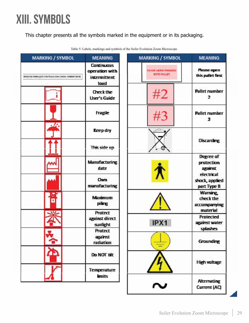
XIII. SymbolsThis chapter presents all the symbols marked in the equipment or in its packaging�
Table 5: Labels, markings and symbols of the Seiler Evolution Zoom Microscope

30 Seiler Evolution Zoom Microscope
XIV. Warning
XV. Term of Warranty• All devices produced by Seiler Instrument are guaranteed to operate pursuant to their
specifications for 12 months from the actual delivery of the product to the customer.
• The guarantee only covers manufacturing defects� It must be emphasized Seiler Instrument does NOT bear transportation and storage costs in the event posterior external maintenance is needed for the equipment�
• The warranty will be canceled automatically if the device is used in any manner other than the recommended one, if it sustains electrical and/or mechanical damage or if it is violated�
• Seiler Instrument is NOT liable for personal damage or other injuries resulting from the improper use of the device�
• Seiler Instrument’s liability regarding this device and its results is limited to its value�
XVI. Contact InformationCorporate Headquarters:3433 Tree Court Industrial Blvd�
St� Louis, MO 63122
Toll-Free: 800-489-2282
Local: 314-968-2282
Fax: 314-968-3601
Email: [email protected]
Web: www.seilermicro.com
Please Note: Seiler Instrument is NOT liable for the device if it is opened and/or altered by unauthorized parties.
Please Note: If the device is used in a manner other than that specified in this Manual, its warranty will be automatically canceled. Read the use conditions carefully. If you have any question, please contact our AUTHORIZED TECHNICAL ASSISTANCE.

31 Seiler Evolution Zoom Microscope
XVII. Owners Record
XVIII. Notes
Model Number
Serial Number
Date Purchased
Location Purchased

32 Seiler Evolution Zoom Microscope
Application of Council Directive: 2004/108/EC - EMC Directive & Application of Council Directive: 93/42/EEC – Medical Device Directive
Standards to which Conformity is Declared: EN 60601-1: 2007 including:
CISPR 11:2015/A1, EN 61000-3-2:2014/A2:2009, EN 61000-3-3:2013, EN 61000-6-1:2007 including:
EN 61000-4-2:2008, EN 61000-4-3:2006/A1:2007/A2:2010, EN 61000-4-4:2012, EN 61000-4-5:2014, EN 61000-4-6:2013, EN 61000-4-8:2009, EN 61000-4-11: 2004
EN 62471:2008, EN 60601-1:2007 Applicant: Seiler Instrument Address: 3433 Tree Court Industrial Blvd St. Louis, MO 63122 Tel: (314) 218-6365
Product Tested: Evolution Zoom, EVO-100-ZLED, EVO-100-LEDXY EVO-100-ZLEDXY
Tested By: ITC Engineering Services, Inc. 9959 Calaveras Road, PO Box 543 Sunol, California 94586-0543 Tel: 925.862.2944 Fax: 925.862.9013 Email: [email protected] http://www.itcemc.com
Date of Issue: April 5, 2016
Report Numbers: 20160215-01 (EMC) 20160215-01 (62471) 20160215-01 (LVD)
I, the undersigned hereby declare that the model(s) listed above was tested and conforms to the Directives and Standards listed above.
Certified By: Date April 14. 2016 Mr. Michael Gbadebo, PE (California License # 11303) Chief Engineer/Principal Consultant
ISO/IEC17025:2005 Accredited Laboratory

33 Seiler Evolution Zoom Microscope
Application of Council Directive: 2004/108/EC - EMC Directive & Application of Council Directive: 93/42/EEC – Medical Device Directive
Standards to which Conformity is Declared: EN 60601-1: 2007 including:
CISPR 11:2015/A1, EN 61000-3-2:2014/A2:2009, EN 61000-3-3:2013, EN 61000-6-1:2007 including:
EN 61000-4-2:2008, EN 61000-4-3:2006/A1:2007/A2:2010, EN 61000-4-4:2012, EN 61000-4-5:2014, EN 61000-4-6:2013, EN 61000-4-8:2009, EN 61000-4-11: 2004
EN 62471:2008, EN 60601-1:2007 Applicant: Seiler Instrument Address: 3433 Tree Court Industrial Blvd St. Louis, MO 63122 Tel: (314) 218-6365
Product Tested: Evolution Zoom, EVO-100-Z, EVO-100-XY EVO-100-Z-XY-RED
Tested By: ITC Engineering Services, Inc. 9959 Calaveras Road, PO Box 543 Sunol, California 94586-0543 Tel: 925.862.2944 Fax: 925.862.9013 Email: [email protected] http://www.itcemc.com
Date of Issue: April 5, 2016
Report Numbers: 20160328-01 (EMC) 20160328-01 (62471) 20160328-01 (LVD)
I, the undersigned hereby declare that the model(s) listed above was tested and conforms to the Directives and Standards listed above.
Certified By: Date April 21. 2016 Mr. Michael Gbadebo, PE (California License # 11303) Chief Engineer/Principal Consultant
ISO/IEC17025:2005 Accredited Laboratory

34 Seiler Evolution Zoom Microscope
LIFETIME WARRANTYExcept as set forth in this Limited Lifetime Warranty, Seiler Instrument Company (“SIC”) hereby warrants that each Seiler microscope product manufactured and/or sold by SIC shall be free from defects in materials and workmanship under normal use and service for the life of the product. Lifetime Warranty includes mechanics, optics, hardware (such as casters, knobs, tension band). This warranty is non-transferable and is valid only with respect to the original purchaser of the product. SIC obligation under this warranty shall be limited to repairing or replacing, at SIC facility and at SIC expense, any parts or components which are demonstrated to be defective. The purchaser shall be responsible for shipment of the product to SIC facility at 3433 Tree Court Industrial Blvd., St. Louis MO 63122, Attention: Micro Product Department, or such other facility as SIC may otherwise designate. Under certain circumstances which are pre-approved by SIC, necessary repairs may be made at the purchaser’s facility. A return authorization is required before returning any product for warranty service by calling 1-800-489-2282 x347.
This warranty shall not apply to electronic and electrical components of the microscope or accessories such as video equipment, monitors and laptop which carry a three (3) year warranty OR any components which are consumable or are required to be replaced or disposed of in normal use of the product, such as lamps, fiber-optic cables and rubber eye cups OR any product which was purchased prior to April 29, 2016.
This warranty shall be void and of no effect: (1) if the product is damaged due to misuse, use in a manner other than pursuant to the instruction for the use of the product, abuse, physical mishandling or natural causes such as flood, fire, earthquake or other perils, as determined by SIC, or (2) if any repairs are made by persons unauthorized by SIC to perform such services.
The warranties set forth here are in lieu of any and all other warranties expressed or implied, including, without limitation, warranties of merchantability and fitness for a particular purpose. Purchaser’s rights thereunder are granted in lieu of any other rights purchaser may have and purchaser hereby waives all other rights, warranties, remedies or guarantees whatsoever with respect to the product. SIC shall not be liable for any reason to any third parties in respect of the product or its performance. Further, SIC shall not be liable for, and purchaser hereby releases SIC from any direct, indirect, consequential, special, incidental or punitive damages in respect to the product. In no event shall SIC be liable for any breach of warranty or other claim in an amount exceeding the purchase price of the product.
The customer is responsible for the shipping costs to Seiler Instrument Company. Seiler Instrument Company will pay the most economical method of shipping back to the customer. Any special shipping method will be paid by the customer.
MEDICAL DIVISION
Toll-Free: 800.489.2282 | Local: 314.968.2282 | Fax: 314.968.3601 | E-mail: [email protected] | www.seilerinst.com
Warranty must be registered online at: http://www.seilermicro.com/products/warranty-registration/
Dear Purchaser,
Congratulations on the purchase of your microscope. Your instrument has been carefully assembled and shipped to you. Please complete the Warranty Registration online at the link below and answer the questions to activate and guarantee your warranty. Retain this warranty document for your records.
Thank you for purchasing a Seiler microscope.
NEW MICROSCOPE MODELS REV. APRIL 2016

35 Seiler Evolution Zoom Microscope
INTERNATIONAL WARRANTYExcept as set forth in this Three (3) Year International Warranty, Seiler Instrument Company (“SIC”) hereby warrants that each Seiler microscope product manufactured and/or sold by SIC shall be free from defects in materials and workmanship under normal use and service for three years. International Warranty includes mechanics, optics, and hardware (such as casters, knobs, tension band). This warranty is non-transferable and is valid only with respect to the original purchaser of the product. SIC obligation under this warranty shall be limited to repairing or replacing, at SIC facility and at SIC expense, any parts or components which are demonstrated to be defective. The purchaser shall be responsible for shipment of the product to SIC facility at 3433 Tree Court Industrial Blvd., St. Louis MO 63122, Attention: Micro Product Department, or such other facility as SIC may otherwise designate. Under certain circumstances which are pre-approved by SIC, necessary repairs may be made at the purchaser’s facility. A return authorization is required before returning any product for warranty service by calling 1-800-489-2282 x347.
This warranty shall not apply to electronic and electrical components of the microscope or accessories such as video equipment, monitors and laptop which carry a three (3) year warranty OR any components which are consumable or are required to be replaced or disposed of in normal use of the product, such as lamps, fiber-optic cables and rubber eye cups OR any product which was purchased prior to April 29, 2016.
This warranty shall be void and of no effect: (1) if the product is damaged due to misuse, use in a manner other than pursuant to the instruction for the use of the product, abuse, physical mishandling or natural causes such as flood, fire, earthquake or other perils, as determined by SIC, or (2) if any repairs are made by persons unauthorized by SIC to perform such services.
The warranties set forth here are in lieu of any and all other warranties expressed or implied, including, without limitation, warranties of merchantability and fitness for a particular purpose. Purchaser’s rights thereunder are granted in lieu of any other rights purchaser may have and purchaser hereby waives all other rights, warranties, remedies or guarantees whatsoever with respect to the product. SIC shall not be liable for any reason to any third parties in respect of the product or its performance. Further, SIC shall not be liable for, and purchaser hereby releases SIC from any direct, indirect, consequential, special, incidental or punitive damages in respect to the product. In no event shall SIC be liable for any breach of warranty or other claim in an amount exceeding the purchase price of the product.
The customer is responsible for the shipping costs to Seiler Instrument Company. Seiler Instrument Company will pay the most economical method of shipping back to the customer. Any special shipping method will be paid by the customer.
MEDICAL DIVISION
Toll-Free: 800.489.2282 | Local: 314.968.2282 | Fax: 314.968.3601 | E-mail: [email protected] | www.seilerinst.com
Warranty must be registered online at: http://www.seilermicro.com/products/warranty-registration/
Dear Purchaser,
Congratulations on the purchase of your microscope. Your instrument has been carefully assembled and shipped to you. Please complete the Warranty Registration online at the link below and answer the questions to activate and guarantee your warranty. Retain this warranty document for your records.
Thank you for purchasing a Seiler microscope.
INTERNATIONAL REV. APRIL 2016

3433 Tree Court Industrial Blvd� St� Louis, MO 63122
USA
Toll-Free: 800-489-2282Local: 314-968-2282Fax: 314-968-3601
Email: [email protected]: www.seilermicro.com
Version April 2017