evolution of switching techniques
TRANSCRIPT

chow CS522 F2001—Multiplexing and Switching—10/17/2001—Page 1
Evolution of Switching Techniques1. Dedicate Channel. Separate wire frequency division multiplexing (FDM) time
division multiplexing (TDM)
availablebandwidth
TimeTDM
Channel 1234
TimeFDM
FrequencyFrequency
1 2 3 4 1 2 3 4 1 2 3 4
Multiplexor (MUX)(Concentrator)
individual lines shared high speed line
DemultiplexorDEMUX
individual lines
chow CS522 F2001—Multiplexing and Switching—10/17/2001—Page 2
Frequency Division Multiplexing (FDM)

chow CS522 F2001—Multiplexing and Switching—10/17/2001—Page 3
Wavelength Division Multiplexing
chow CS522 F2001—Multiplexing and Switching—10/17/2001—Page 4
Impact of WDM� Many big organizations are starting projects to design WDM system or DWDN
(Dense Wave Division Mutiplexing Network). We may see products appear in next three years.In Fujitsu and CCL/Taiwan, 128 different wavelengthes on the same strand of fiber was reported working in the lab.
� We may have optical routers between end systems that can take one wavelenght signal, covert to different wavelenght, send it out on different links. Some are designing traditional routers that covert optical signal to electronical signal, and use time slot interchange based on high speed memory to do the switching, the convert the electronic signal back to optical signal.
� With this type of optical networks, we will have a virtual circuit network, where each connection is assigned some wave length. Each connection can have 2.4 gbps tremedous bandwidth.
� With inital 128 different wavelength, we can have about 10 end users. If each pair of end users needs to communicate simultaneously, it will use 10*10=100 different wavelength.
� There is an issue of protocol layering. Should we have IP/DWDN directly, or IP/Sonet/DWDN? No one is talking about IP/ATM/Sonet/DWDN.
chow CS522 F2001—Multiplexing and Switching—10/17/2001—Page 5
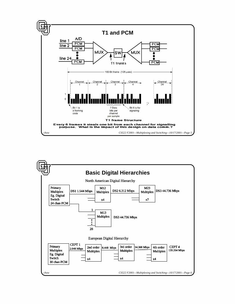
T1 and PCM
chow CS522 F2001—Multiplexing and Switching—10/17/2001—Page 6
Basic Digital HierarchiesNorth American Digital Hierarchy
PrimaryMultiplexEg. DigitalSwitch30 chan PCM
4th orderMultiplex
x4
2nd orderMultiplex
x4
3rd orderMultiplex
x4
34.368 Mbps2.048 Mbps 8.448 Mbps139.264 Mbps
CEPT 1CEPT 4
European Digital Hierarchy
28
M13Multiplex
M23Multiplex
x7
PrimaryMultiplexEg. DigitalSwitch24 chan PCM
M12Multiplex
x4
1
DS3 44.736 Mbps
DS1 1.544 Mbps DS2 6.312 Mbps DS3 44.736 Mbps
�
�
�
North American Digital Hierarchy
PrimaryMultiplexEg. DigitalSwitch30 chan PCM
4th orderMultiplex
x4
2nd orderMultiplex
x4
3rd orderMultiplex
x4
34.368 Mbps2.048 Mbps 8.448 Mbps139.264 Mbps
CEPT 1CEPT 4Primary
MultiplexEg. DigitalSwitch30 chan PCM
4th orderMultiplex
x4
2nd orderMultiplex
x4
3rd orderMultiplex
x4
34.368 Mbps2.048 Mbps 8.448 Mbps139.264 Mbps
CEPT 1CEPT 4
European Digital Hierarchy
28
M13Multiplex
M23Multiplex
x7
PrimaryMultiplexEg. DigitalSwitch24 chan PCM
M12Multiplex
x4
1
DS3 44.736 Mbps
DS1 1.544 Mbps DS2 6.312 Mbps DS3 44.736 Mbps
�
�
�
28
M13Multiplex
M23Multiplex
x7
PrimaryMultiplexEg. DigitalSwitch24 chan PCM
M12Multiplex
x4
1
DS3 44.736 Mbps
DS1 1.544 Mbps DS2 6.312 Mbps DS3 44.736 Mbps
�
�
�

chow CS522 F2001—Multiplexing and Switching—10/17/2001—Page 7
SONET (Synchronous Optical NETwork)
Dual ringis a commontopologyfor SONET.
SPE: synchronous payload dataThis is STS-1 framewith 9x90 bytes
STS-3 frame has 9x270 bytes
Frame rate is 8000per second.
(155.52 Mbps).
(51.84 Mbps).
chow CS522 F2001—Multiplexing and Switching—10/17/2001—Page 8
SONET and SDH Multiplex RateSDH (Synchronous Digital Hierarchy) STS (Synchronous Transport Signal)
SONET SDH Data Rate (Mbps)
Electrical Optical Optical Gross SPE User
STS-1 OC-1 51.84 50.112 49.536
STS-3 OC-3 STM-1 155.52 150.336 148.608
STS-9 OC-9 STM-3 466.56 451.008 445.824
STS-12 OC-12 STM-4 622.08 601.344 594.432
STS-18 OC-18 STM-6 933.12 902.016 891.648
STS-24 OC-24 STM-8 1244.16 1202.688 1188.864
STS-36 OC-36 STM-12 1866.24 1804.032 1783.296
STS-48 OC-48 STM-16 2488.32 2405.376 2377.728
STS-192 OC-192 STM-64 9953.28

chow CS522 F2001—Multiplexing and Switching—10/17/2001—Page 9
SONET Multiplexing
Low-SpeedMappingFunction
MediumSpeed
MappingFunction
High-Speed
MappingFunction
DS3
44.736
DS1
DS2
CEPT-1
CEPT-4
139.264
ATM
150 Mbps
STS-1
STS-1
STS-1STS-1STS-1
STS-1STS-1STS-1
STS-3c
STS-3c
OC-n
Scrambler E/O
51.84 Mbps
High-Speed
MappingFunction
MuxSTS-n
�
�
�
�
�
�
Low-SpeedMappingFunction
MediumSpeed
MappingFunction
High-Speed
MappingFunction
DS3
44.736
DS1
DS2
CEPT-1
CEPT-4
139.264
ATM
150 Mbps
STS-1
STS-1
STS-1STS-1STS-1
STS-1STS-1STS-1
STS-3c
STS-3c
OC-n
Scrambler E/O
51.84 Mbps
High-Speed
MappingFunction
MuxSTS-n
�
�
�
�
�
�
tributary: component streams
chow CS522 F2001—Multiplexing and Switching—10/17/2001—Page 10
SONET Add-Drop Multiplexor (ADM)
MUX DEMUX MUX DEMUX
MUX DEMUX
(a) pre-SONET multiplexing
removetributary
inserttributary
ADM
removetributary
inserttributary
(b) SONET Add-Drop multiplexing
MUX DEMUX MUX DEMUXMUX DEMUX MUX DEMUX
MUX DEMUX
(a) pre-SONET multiplexing
removetributary
inserttributary
ADM
removetributary
inserttributary
(b) SONET Add-Drop multiplexing
Tributary can be inserted/removed
without disturbing others

chow CS522 F2001—Multiplexing and Switching—10/17/2001—Page 11
Configure Logical Networks Using ADM
a
b c
logical fully-connected net
(a)
a
b
c
3 ADMs connected inphysical ring topology
OC-3nOC-3n
OC-3n
(b)
a
b c
logical fully-connected net
a
b c
logical fully-connected net
(a)
a
b
c
3 ADMs connected inphysical ring topology
OC-3nOC-3n
OC-3n
a
b
c
3 ADMs connected inphysical ring topology
OC-3nOC-3n
OC-3n
(b)
chow CS522 F2001—Multiplexing and Switching—10/17/2001—Page 12
SONET Self-Healing Ring
a
b
c
d
a
b
c
d
(a) Dual ring (b) Loop-around in response to fault
a
b
c
d
a
b
c
d
a
b
c
d
a
b
c
d
(a) Dual ring (b) Loop-around in response to fault
restoration can be done in 50 msec

chow CS522 F2001—Multiplexing and Switching—10/17/2001—Page 13
What is the Network Restoration Problem?
� Types of Failures: Channel, Link, Node, Area, and Transient Failures.� Network Restoration: Process of recovering from network failures.� Types of Restoration Approaches: Centralized, Distributed, Hierarchical.
3
14
7
25
86
NetworkOperation
Center
Tinker Bell Liberty Bell
Taco Bell
n : Switch Node
fiber linkcarries hundreds of thousands calls
Buffalo Bell
LIFE!
chow CS522 F2001—Multiplexing and Switching—10/17/2001—Page 14
Evolution of Switching Techniques2. Circuit Switching
using FDM or TDM with demand (dynamic channel assignment)e.g. old telephone networks, satellites.difficulties in handling computer data traffic:
� demand assignment per “message” ⇒ relative long set-up time.� demand assignment per “session” ⇒ low utilization.
3. Message Switchingwith data concentrator for long distance high-speed linealso called statistical multiplexing or
ATDM (Asynchronous Time-Division Multiplexing)used in stored-and-forward network.Note: addresses needed to identify messages.
4. Packet Switchingvariable size messages from host segmented into small packets.advantages—simultaneous parallel path possible;
pipelining in multihop network.Problems— disassembly, reassembly, sequencing, support real-time traffic.

chow CS522 F2001—Multiplexing and Switching—10/17/2001—Page 15
Circuit Switching vs. Packet Switching: Network
chow CS522 F2001—Multiplexing and Switching—10/17/2001—Page 16
Delay Analysis of a Circuit Switch Network
Tcsd
Tmtd
CR
CR
CR
CA
d
ddd
no. of hops+1
d: propagation delayCR: Call Request messageCA: Call Accept messageTcsd: Total call setup delayTmtd: Total message transmission L: message length (bits)b: transmission speed (bps)
Assume all hops of the same b andthen Total circuit switching delay=Tcsd + Tmtd= Tcsd + (3d + L/b)
Note that there is no packet heade

chow CS522 F2001—Multiplexing and Switching—10/17/2001—Page 17
Timing Analysis of Ckt SW, Msg SW and Pkt SW
chow CS522 F2001—Multiplexing and Switching—10/17/2001—Page 18
Important Network Design Parameters for Analyzing Network Performance
Propagation delay refers to how long it takes for a bit to traverse a link. It depends on the distance and the signal propagation speed.Example: 10km distance, 2*108 m/sec propagation speed.
Propagation delay = distance / signal propagation speedTransmission delay = message size / transmission speedQueueing delay depends on � how many requests on the queue and � how fast the node can process them.

chow CS522 F2001—Multiplexing and Switching—10/17/2001—Page 19
Evolution of Switching Techniques5. Cell Switching
chop messages into tiny fixed size packets called ATM cell (53 bytes)ATM: Asynchronous Transfer Mode
advantages—much better response time of small message trafficprovision for guarantee bandwidth ⇒ support real-time traffic.
disadvantages—too much overhead; (5 bytes header).
fileserver
A
B
C
D
SW1 SW2
ABCD
packet switching
A1B1CDA3 A2A4 B3 B2B4
shorter delay forsmaller messages
additional segmentation/assembly required
ATMSwitching
chow CS522 F2001—Multiplexing and Switching—10/17/2001—Page 20
Network with Links and SwitchesSwitches can be divided into two classes:� Space-division switches: provide separate physical connections between
inputs and outputs (ports).� Time-division switches: network flow are time-division multiplexed streams.
User 1
SwitchLink
User n
User n-1User 1
SwitchLink
User n
User n-1
Control
123
N
123
N
Connectionof inputs to outputs�
�
�
�
�
�
Control
123
N
123
N
Connectionof inputs to outputs�
�
�
�
�
�
Switch

chow CS522 F2001—Multiplexing and Switching—10/17/2001—Page 21
Time Division Switch
Time division switch is used in the circuit switching systems.How to set up a connection through the time division switch?What is the relationship between the memory access time (T) of RAM buffer
and the number of slots/channels (n) in the frame, assuming a frame period of 125 µsec (8000frames/sec)?
chow CS522 F2001—Multiplexing and Switching—10/17/2001—Page 22
Time Division Switch� Here we assume this a telephony network where frames (big or small) are sent
at 8000 frames/sec frame rate, i.e., 125 µsec per frame.� A separate signaling (call setup) channel is used to tell the switch which pairs
of users are trying communicate each other. It results in the mapping table content shown above. Here the mapping table shows (channel0 talks to channel 4, channel1 to channel7, channel2 to channel6)
� There are two basic ways to implement this time slot interchange:� Sequential write to RAM, random read out of RAM:
In this approach, channel data are written to the RAM sequentially, i.e., data of the first channel is written to the first word of the RAM.After all data is in, the data in RAM are read according to the mapping table to form the outgoing frame. For example, the first time slot of the outgoing frame is filled with the 4th word of RAM, the 2nd time slot is filled with 7th word.
� Random write to RAM, sequential read out of RAM:In this approach, the time slot data in the incoming frame are written to the RAM “randomly” according to the mapping table. After all data is in, the data in RAM are read sequentially to form the outgoing frame.
� The outgoing frame cannot be sent until the whole incoming frame is read.

chow CS522 F2001—Multiplexing and Switching—10/17/2001—Page 23
Crosspoint Switch and Multistage Switch
chow CS522 F2001—Multiplexing and Switching—10/17/2001—Page 24
����53 Byte�����������
���������������
��
��
��
����������������������� ���
��
���������� ����� ��
���������������������������
������������ ������������������������
�����
��������������������������������
����� ���
��������������������������
���
������
��������
���
�����
���������
CRC-8
CRC-10

chow CS522 F2001—Multiplexing and Switching—10/17/2001—Page 25
ATM Switch Structure
Control Processor: connection management, bandwidth allocation, maintenance.IC: cell buffering, VCI/VPI translation, cell filtering, ATM policing, cell alignment,
and output port contention resolution.OC: cell buffering, VCI/VPI translation for multicast cells.
SwitchFabric
IC
IC
1
N
Input Ports Output Ports
IC: Input ControllerOC: Output Controller
ControlProcessor
OC
OC
1
N
in-band call management msg
ATMcell ATMcell
rt:routing tag
rt
chow CS522 F2001—Multiplexing and Switching—10/17/2001—Page 26
Space Division Switching Elements2x2 Switches
Possible States of 2x2 Sw
0 port1
01
01
01
stuck on 0
0-broadcast
cross-over
straight-through
Self-RoutingUsing routing tag of cellto select the 2x2 Sw state
0
bit in routing tag
0
11
2x2 configure as routerAB
H=Max(A, B)
L=Min(A, B)
AB H=Max(A, B)
L=Min(A, B)
2x2 configure as sorter
1110
1011
11>10 set 2x2 to cross-over state
bitonic
route bit 0
routing bit 1
cell go to port 0
cell go to port 1
arrow point to the port to receive bigger routing tag

chow CS522 F2001—Multiplexing and Switching—10/17/2001—Page 27
Cell Routing in A Batcher-Banyan Switch
Those lines without input cell is assume to have very large routing tag value.Batcher sorting switch sorts the cells according to the routing tag values.For this work, in a given cycle, no two cells go to the same output port.
The nth stage of banyan switch interprets the nth bit of routing tags as routing bit.
chow CS522 F2001—Multiplexing and Switching—10/17/2001—Page 28
Exercise Cell SwitchingProb. 3. Batcher-Banyan Switch. Draw the 2x2 element configurations along the
routes for those 4 cells.
01
01
01
01
01
01
01
01
01
01
01
01
72
13
Batcher Network Banyan Network
1st 3-stage Network2nd 3-stage Network
2
277
7
2
3
1 31
3
1
2
7
3
1
2
37
1 2
37
1
010
111
001
011
001
010
011
111
001
011
010
111 111
010011
001

chow CS522 F2001—Multiplexing and Switching—10/17/2001—Page 29
Telephone Network: LEC(RBOC), IXC� Local Exachnage Carriers (LECs) consist of Regional Bell Operating
Companies (RBOCs).� Interexchnage Carriers (IXCs) consist of AT&T, MCI, Sprint.� LATA: Local Access and Transport Area operated by LECs.� IXC has POP (point of presence) in some LATA switches.
LATA 1LEC such as US West
LATA 2LEC such as Bell South
net 1
net 2
IXC such as MCI
LATA 1LEC such as US West
LATA 2LEC such as Bell South
net 1
net 2
IXC such as MCI
chow CS522 F2001—Multiplexing and Switching—10/17/2001—Page 30
Signaling Network
STP
STP
STP
STP
SSP SSP
Transport Network
Signaling Network
SSP = Service switching point (signal to message)STP = Signal transfer point (message transfer)SCP = Service control point (processing)
SCP
STP
STP
STP
STP
SSP SSP
Transport Network
Signaling Network
SSP = Service switching point (signal to message)STP = Signal transfer point (message transfer)SCP = Service control point (processing)
SCPSCP
SPC
Control Signaling Message
SPC
Control Signaling Message
Stored Program Control swtiches

chow CS522 F2001—Multiplexing and Switching—10/17/2001—Page 31
Intelligent Networks
SSPSSP
Transport Network
ExternalDatabase
SignalingNetwork Intelligent
PeripheralSSP
SSP
Transport Network
ExternalDatabase
SignalingNetwork Intelligent
Peripheral
Provides services using enhanced signaling networks.� Caller ID, voice mail, voice recognition, call screening, call back...
chow CS522 F2001—Multiplexing and Switching—10/17/2001—Page 32
Signalling System #7a packet network that control the setting up, managing, and releasing of telephone
call. It also supports, IN, mobile cellular networks, and ISDN.
It has its own layering called part and related message format.It is used by a cellular network to communication with LECs or IXCs.
Application Layer
Transport Layer
Network Layer
Data Link Layer
Physical Layer
Presentation Layer
Session Layer
SCCP
MTP Level 3
MTP Level 2
MTP Level 1
ISUPTCAPTUP
Application Layer
Transport Layer
Network Layer
Data Link Layer
Physical Layer
Presentation Layer
Session Layer
SCCP
MTP Level 3
MTP Level 2
MTP Level 1
ISUPTCAPTUP

chow CS522 F2001—Multiplexing and Switching—10/17/2001—Page 33
Components of Cellular Networks
AC = authentication centerBSS = base station subsystemEIR = equipment identity registerHLR = home location register
wirelineterminal
MSC
PSTN
BSS BSS
STP SS#7HLRVLR
EIRAC
MSC = mobile switching center PSTN = public switched telephone networkSTP = signal transfer pointVLR = visitor location register
AC = authentication centerBSS = base station subsystemEIR = equipment identity registerHLR = home location register
wirelineterminal
MSC
PSTN
BSS BSS
STP SS#7HLRVLR
EIRAC
MSC = mobile switching center PSTN = public switched telephone networkSTP = signal transfer pointVLR = visitor location register
chow CS522 F2001—Multiplexing and Switching—10/17/2001—Page 34
Paging System vs. Cellular Phone Systemone way communication vs. two way communicationsSome companies to offer integrated system that provides both services.Advanced paging system can relay email/bulletin board messages.
chow CS522 F2001—Multiplexing and Switching—10/17/2001—Page 35
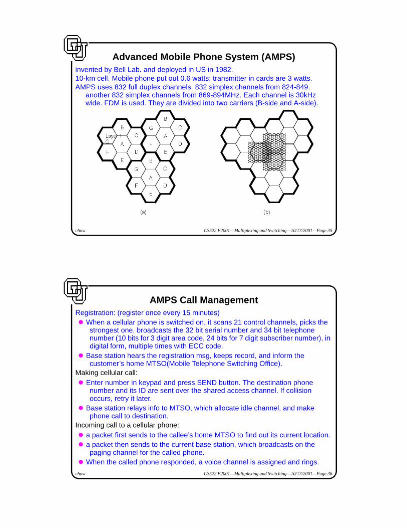
Advanced Mobile Phone System (AMPS)invented by Bell Lab. and deployed in US in 1982.10-km cell. Mobile phone put out 0.6 watts; transmitter in cards are 3 watts.AMPS uses 832 full duplex channels. 832 simplex channels from 824-849,
another 832 simplex channels from 869-894MHz. Each channel is 30kHz wide. FDM is used. They are divided into two carriers (B-side and A-side).
chow CS522 F2001—Multiplexing and Switching—10/17/2001—Page 36
AMPS Call ManagementRegistration: (register once every 15 minutes)� When a cellular phone is switched on, it scans 21 control channels, picks the
strongest one, broadcasts the 32 bit serial number and 34 bit telephone number (10 bits for 3 digit area code, 24 bits for 7 digit subscriber number), in digital form, multiple times with ECC code.
� Base station hears the registration msg, keeps record, and inform the customer’s home MTSO(Mobile Telephone Switching Office).
Making cellular call:� Enter number in keypad and press SEND button. The destination phone
number and its ID are sent over the shared access channel. If collision occurs, retry it later.
� Base station relays info to MTSO, which allocate idle channel, and make phone call to destination.
Incoming call to a cellular phone:� a packet first sends to the callee’s home MTSO to find out its current location.� a packet then sends to the current base station, which broadcasts on the
paging channel for the called phone.� When the called phone responded, a voice channel is assigned and rings.

chow CS522 F2001—Multiplexing and Switching—10/17/2001—Page 37
Personal Communications Services (PCS)� Use CDMA (Code Division Multiplexing Access).� Microcell (50-100 meters) 0.25 watt light weight terminal.� Small base station, toaster size, called telepoints, on top of telephone/light
pole.� Use 1.7-2.3 GHz spectrum.� FCC auction off licenses to use PCS spectrum in 1994-5. Get 7.7 billion
dollars.� The original users in the spectrum needs to be relocated. Who should pay
that?
chow CS522 F2001—Multiplexing and Switching—10/17/2001—Page 38
Iradium Project� Use 77 LEO (low earth orbit) satellites. � Revised to 66 LEO, 1628 moving cells.� Provide world-wide telecommunication services among hand-held devices
using those LEO satellites.� The coverage areas of PCS or Current Cellular systems are limited. You pay
more for access if you are not in the area of your subscriber.