evolution of strain states and textures during roll-cladding in sts/al/sts sheets
TRANSCRIPT

MECHANOCHEMISTRY AND MECHANICAL ALLOYING 2003
J O U R N A L O F M A T E R I A L S S C I E N C E 3 9 (2 0 0 4 ) 5371 – 5374
Evolution of strain states and textures during
roll-cladding in STS/Al/STS sheets
JONG-KOOK KIM, MOO-YOUNG HUH∗, JAE-CHUL LEEDivision of Materials Science and Engineering, Korea University, Seoul 136-701, KoreaE-mail: [email protected]
KWANG-KOO JEEDivision of Materials, Korea Institute of Science and Technology, Seoul 136-791, Korea
OLAF ENGLERHydro Aluminium Deutschland GmbH, R+D Center Bonn, P.O. Box 2468, D–53014 Bonn,Germany
The evolution of strain states and textures during roll-cladding of three plies of sheetscomprising ferritic stainless steel (STS), aluminum (Al) and ferritic stainless steel wasinvestigated by measurements of crystallographic textures and by simulations with thefinite element method (FEM). Because the deformation mainly occurs in the Al layer duringroll-cladding, the present investigation was focused on the Al layer located at the middle ofclad samples. Roll-cladding of STS/Al/STS sheets led to the development of a strongthrough thickness texture gradient in the Al sheet which was characterized by sheartextures at the surface layer and rolling textures at the center layer. The temperature of thecladding operation played an important role in the evolution of textures.C© 2004 Kluwer Academic Publishers
1. IntroductionStainless steel (STS) clad aluminum (Al) sheets com-prising STS/Al or STS/Al/STS combine the excellentcorrosion-resistant and mechanical properties of stain-less steel and the high thermal and electrical con-ductivities of aluminum. Roll-cladding is the mostprevalent process to produce stainless steel clad alu-minum sheets because of a fast production rate. Duringthe roll-cladding process, the assembly of STS/Al orSTS/Al/STS is heated to the cladding temperature andthen inserted jointly into the rolling mill. Since bond-ing at the interface of STS and Al is obtained duringrolling, variations of the stain state in the roll gap areof great importance. Several analytical models for theroll-cladding process have been proposed so far. How-ever, these works focused mainly on the prediction ofthe rolling pressure and horizontal stress distributionsin the overall component layers [1, 2].
In the present work, three plies of sheets comprisingtwo outer surfaces of ferritic stainless steel (STS 430)and inner middle of aluminum alloy (AA 3003) wereproduced by roll-cladding at 300◦C and the evolutionof texture and microstructure throughout the samplethickness of AA 3003 was studied in order to exam-ine the variation of strain states during roll-cladding.Furthermore, the strain states during roll cladding wereanalyzed by the finite element method (FEM), and thestrain history data extracted from the FEM computa-
∗ Author to whom all correspondence should be addresed.
tions were also utilized to simulate the deformationtextures at various thickness layers.
2. Experimental procedureIn the present study cold rolled STS 430 sheet witha thickness of 0.5 mm and cold rolled and fully re-crystallized AA 3003 with a thickness of 3.0 mm wereused as initial samples. The assembly of STS 430/AA3003/STS 430 was prepared and heated to 300◦C andthen inserted jointly into the rolling mill with a rolldiameter of 470 mm. During roll-cladding, the totalthickness reduction of the assembly was 30%. Whilethe STS 430 sheets hardly deformed plastically duringroll-cladding, the aluminum sheet was thinned to a finalgauge of about 2.1 mm.
Pole figure measurements were carried out by meansof a conventional X-ray texture goniometer [3]. Fromthree incomplete pole figures, the three-dimensionalorientation distribution functions (ODF) f (g) were cal-culated by the series expansion method according toBunge (lmax = 22) [4]. Most of the pole figures dis-played the typical orthotropic symmetry of a rolledsheet; accordingly, the ODFs were calculated in theEuler angle range of 0◦ ≤ {ϕ1, �, ϕ2} ≤ 90◦. To de-termine the texture variation through the thickness ofAA 3003, texture measurements were performed at thesurface layer (indicated by the parameter s = 1.0)
0022–2461 C© 2004 Kluwer Academic Publishers 5371
MECHANOCHEMISTRY AND MECHANICAL ALLOYING 2003
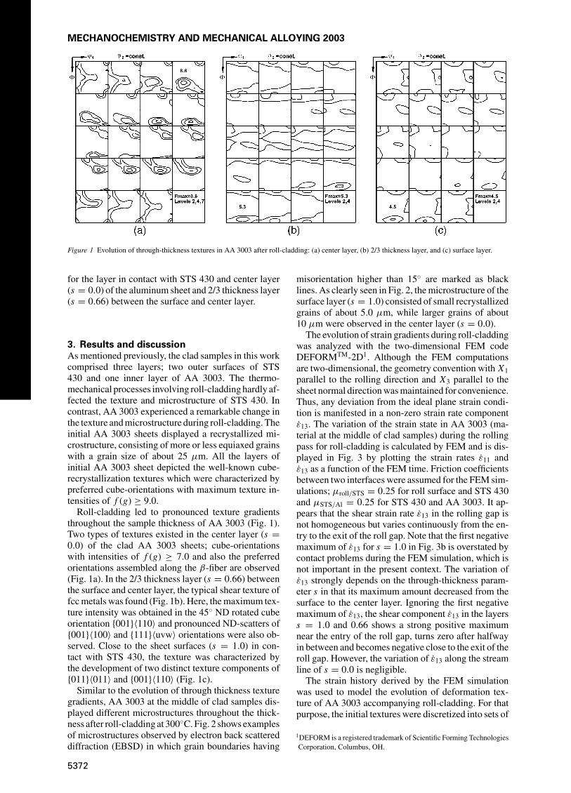
Figure 1 Evolution of through-thickness textures in AA 3003 after roll-cladding: (a) center layer, (b) 2/3 thickness layer, and (c) surface layer.
for the layer in contact with STS 430 and center layer(s = 0.0) of the aluminum sheet and 2/3 thickness layer(s = 0.66) between the surface and center layer.
3. Results and discussionAs mentioned previously, the clad samples in this workcomprised three layers; two outer surfaces of STS430 and one inner layer of AA 3003. The thermo-mechanical processes involving roll-cladding hardly af-fected the texture and microstructure of STS 430. Incontrast, AA 3003 experienced a remarkable change inthe texture and microstructure during roll-cladding. Theinitial AA 3003 sheets displayed a recrystallized mi-crostructure, consisting of more or less equiaxed grainswith a grain size of about 25 µm. All the layers ofinitial AA 3003 sheet depicted the well-known cube-recrystallization textures which were characterized bypreferred cube-orientations with maximum texture in-tensities of f (g) ≥ 9.0.
Roll-cladding led to pronounced texture gradientsthroughout the sample thickness of AA 3003 (Fig. 1).Two types of textures existed in the center layer (s =0.0) of the clad AA 3003 sheets; cube-orientationswith intensities of f (g) ≥ 7.0 and also the preferredorientations assembled along the β-fiber are observed(Fig. 1a). In the 2/3 thickness layer (s = 0.66) betweenthe surface and center layer, the typical shear texture offcc metals was found (Fig. 1b). Here, the maximum tex-ture intensity was obtained in the 45◦ ND rotated cubeorientation {001}〈110〉 and pronounced ND-scatters of{001}〈100〉 and {111}〈uvw〉 orientations were also ob-served. Close to the sheet surfaces (s = 1.0) in con-tact with STS 430, the texture was characterized bythe development of two distinct texture components of{011}〈011〉 and {001}〈110〉 (Fig. 1c).
Similar to the evolution of through thickness texturegradients, AA 3003 at the middle of clad samples dis-played different microstructures throughout the thick-ness after roll-cladding at 300◦C. Fig. 2 shows examplesof microstructures observed by electron back scattereddiffraction (EBSD) in which grain boundaries having
misorientation higher than 15◦ are marked as blacklines. As clearly seen in Fig. 2, the microstructure of thesurface layer (s = 1.0) consisted of small recrystallizedgrains of about 5.0 µm, while larger grains of about10 µm were observed in the center layer (s = 0.0).
The evolution of strain gradients during roll-claddingwas analyzed with the two-dimensional FEM codeDEFORMTM-2D1. Although the FEM computationsare two-dimensional, the geometry convention with X1parallel to the rolling direction and X3 parallel to thesheet normal direction was maintained for convenience.Thus, any deviation from the ideal plane strain condi-tion is manifested in a non-zero strain rate componentε13. The variation of the strain state in AA 3003 (ma-terial at the middle of clad samples) during the rollingpass for roll-cladding is calculated by FEM and is dis-played in Fig. 3 by plotting the strain rates ε11 andε13 as a function of the FEM time. Friction coefficientsbetween two interfaces were assumed for the FEM sim-ulations; µroll/STS = 0.25 for roll surface and STS 430and µSTS/Al = 0.25 for STS 430 and AA 3003. It ap-pears that the shear strain rate ε13 in the rolling gap isnot homogeneous but varies continuously from the en-try to the exit of the roll gap. Note that the first negativemaximum of ε13 for s = 1.0 in Fig. 3b is overstated bycontact problems during the FEM simulation, which isnot important in the present context. The variation ofε13 strongly depends on the through-thickness param-eter s in that its maximum amount decreased from thesurface to the center layer. Ignoring the first negativemaximum of ε13, the shear component ε13 in the layerss = 1.0 and 0.66 shows a strong positive maximumnear the entry of the roll gap, turns zero after halfwayin between and becomes negative close to the exit of theroll gap. However, the variation of ε13 along the streamline of s = 0.0 is negligible.
The strain history derived by the FEM simulationwas used to model the evolution of deformation tex-ture of AA 3003 accompanying roll-cladding. For thatpurpose, the initial textures were discretized into sets of
1DEFORM is a registered trademark of Scientific Forming TechnologiesCorporation, Columbus, OH.
5372

MECHANOCHEMISTRY AND MECHANICAL ALLOYING 2003
Figure 2 EBSD observed from (a) center layer and (b) surface layer of AA 3003.
Figure 3 Strain states in a roll gap calculated by FEM simulation: Variation of (a) ε11 and (b) ε13.
about 4000 individual orientations with equal weights.As described in more detail elsewhere [5], the strainrates εij given by the FEM simulations were fed intothe full constraint polycrystal deformation model (e.g.[6–8]). The rolling pass for cladding was run in about 30steps using constant time increments of �t = 0.023 s.
The simulated results are shown in Fig. 4 in the formof the ODFs for s = 0.0 and s = 0.66, respectively. Forthe sheet center (s = 0.0), the typical rolling texture de-veloped, which is typical of an approximate plane straindeformation state. It was noted that textures simulatedfor s = 1.0 and s = 0.66 were nearly identical. Forboth surface layer (s = 1.0) and 2/3 thickness layer(s = 0.66) pronounced shear textures consisting of{001}〈110〉 and {111}〈uvw〉 were obtained.
Apparently, some texture components at the vari-ous sheet layers obtained experimentally cannot bemodeled by the deformation textures for roll-cladding.These discrepancies between the modeled and exper-imental textures can to a large extent be attributed tothe annealing effect during roll-cladding because thesamples were heated to 300◦C just before rolling. Forthe sheet center (s = 0.0), a mixture of the rollingtexture and cube recrystallization texture developed in
the experimental texture. The deformation during roll-cladding led to the formation of rolling texture com-ponents and subsequently a part of them were recrys-tallized to develop the cube-texture. For both surfacelayer (s = 1.0) and 2/3 thickness layer (s = 0.66)pronounced shear textures consisting of {001}〈110〉and {111}〈uvw〉 were obtained. Recently, Engler etal. [9] showed that recrystallization nucleation at thegrain boundaries gives rise to the occurrence of thesetexture components in the final recrystallization tex-tures of sheet layers with pronounced shear deformationtextures.
Finally, it should be addressed that the formationof strong {011}〈011〉 orientation at the surface layer(s = 1.0) of AA 3003. This orientation has seldombeen reported in rolling and recrystallization texturesof aluminium sheets. It is anticipated that orientationswith a higher stored energy nucleate more easily thanorientations with low stored energy. In the literatureon recrystallization textures it is commonly assumedthat the stored energy of the various texture compo-nents is proportional to their Taylor-factor M (e.g. [9,10]). In our recent work [9], Taylor-factors M werecalculated for the strain conditions for developing the
5373

MECHANOCHEMISTRY AND MECHANICAL ALLOYING 2003
Figure 4 Simulated textures by using the strain states of (a) center layer and (b) 2/3 thickness layer.
rolling texture and shear textures. The maps of Taylorfactors [9] discloses that the highest M is obtained atthe {011}〈011〉 orientation for the strain states devel-oping either the rolling texture or shear textures. Ac-cordingly, the development of {011}〈011〉 at the surfacelayer (s = 1.0) of AA 3003 can be attributed to a pre-ferred nucleation of recrystallization, which dominatesthe formation of recrystallization textures in the surfacelayers.
4. SummaryThree plies of sheets comprising two outer surfacesof STS 430 and inner middle of AA 3003 were pro-duced by roll-cladding at 300◦C and the evolution ofthrough-thickness textures and microstructures in AA3003 was studied. Roll-cladding led to pronounced tex-ture gradients throughout the sample thickness of AA3003: Strong cube-orientations and preferred orienta-tions assembled along the β-fiber are observed in thecenter layer. Close to the sheet surfaces in contact withSTS 430, the texture was characterized by the develop-ment of two distinct texture components of {011}〈011〉and {001}〈110〉 . Difference in strain states at differ-ent thickness layers and the subsequent recrystalliza-tion process during roll-cladding are responsible forthe evolution of textures in AA 3003.
AcknowledgementsThis work was supported by grant No. PS006-1-00-01 from the Center for Advanced Materials Processing(CAMP).
References1. R . R . A R N O L D and P . W. W H I T T O N , Proc. Inst. Mech. Eng.
173 (1959) 241.2. G . E . A R K U L I S , “Compound Plastic Deformation of Lay-
ers of Different Metals” (Daniel Davey & Co., INC, New York,1965).
3. V . R A N D L E and O. E N G L E R , “Introduction to Texture Analy-sis, Macrotexture, Microtexture and Orientation Mapping” (Gordonand Breach, Amsterdam, 2000).
4. H . J . B U N G E , “Texture Analysis in Materials Science” (Butter-worths, London, 1982).
5. O . E N G L E R, M. Y. H U H and C. N. T O M E, Metall. Mater.Trans. A 31 (2000) 2299.
6. J . H I R S C H and K. L UC K E , Acta Metall. 36 (1988) 2883.7. U . F . K O C K S , Metall. Trans. 1 (1970) 1121.8. J . G I L S E V I L L A N O, P . V A N H O U T T E and E .
A E R N O U D T , Prog. Mater. Sci. 25 (1980) 69.9. O . E N G L E R, H. C . K I M and M. Y. H U H , Mater. Sci. Technol.
17 (2001) 74.10. I . S A M A J D A R, B . V E R L I N D E N, P . V A N H O U T T E and
D. V A N D E R S C H U E R E N , Mater. Sci. Eng. A 238 (1997) 343.
Received 11 September 2003and accepted 27 February 2004
5374