evolution 3d/4d user manual massage chair the arm …
TRANSCRIPT
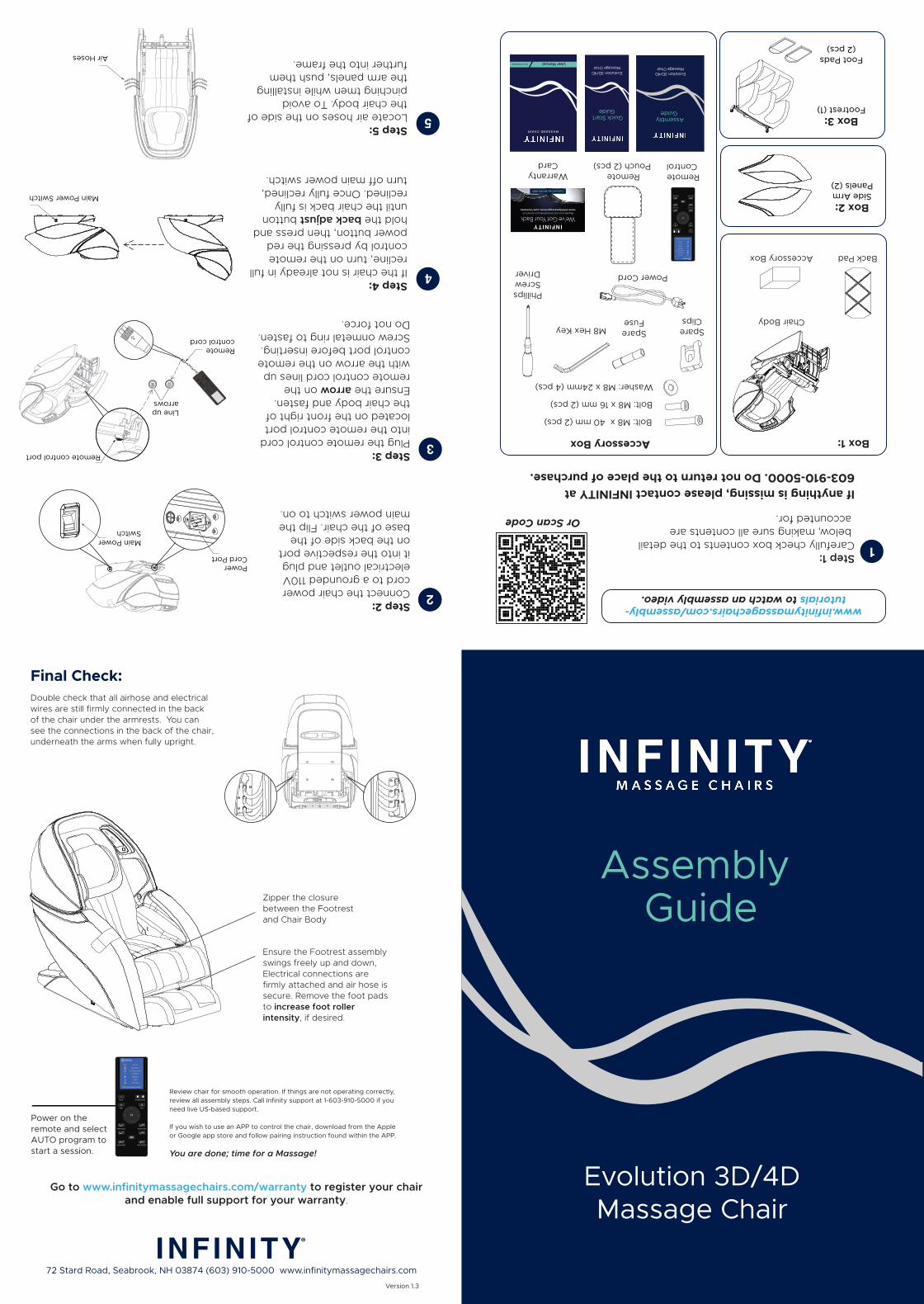
Power on the remote and select AUTO program to start a session.
Accessory Box
Evolution 3D/4DMassage Chair
Quick Start Guide
User ManualEVOLUTION 3D/4D
MASSAGE CHAIR
Evolution 3D/4DMassage Chair
Assembly Guide
72 Stard Road, Seabrook, NH 03874 (603) 910-5000 www.infinitymassagechairs.com
Double check that all airhose and electrical wires are still firmly connected in the back of the chair under the armrests. You can see the connections in the back of the chair, underneath the arms when fully upright.
Evolution 3D/4DMassage Chair
Assembly Guide
Go to www.infinitymassagechairs.com/warranty to register your chair and enable full support for your warranty.
1Step 1:Carefully check box contents to the detail below, making sure all contents are accounted for.
If anything is missing, please contact INFINITY at 603-910-5000. Do not return to the place of purchase.
Box 1:
Box 2: Side Arm Panels (2)
Box 3: Footrest (1)
Foot Pads (2 pcs)
www.infinitymassagechairs.com/assembly-tutorials to watch an assembly video.
Or Scan Code
Accessory Box
Chair Body
2Step 2:Connect the chair power cord to a grounded 110V electrical outlet and plug it into the respective port on the back side of the base of the chair. Flip the main power switch to on.
Step 3:Plug the remote control cord into the remote control port located on the front right of the chair body and fasten. Ensure the arrow on the remote control cord lines up with the arrow on the remote control port before inserting. Screw onmetal ring to fasten. Do not force.
3
Step 4:If the chair is not already in full recline, turn on the remote control by pressing the red power button, then press and hold the back adjust button until the chair back is fully reclined. Once fully reclined, turn off main power switch.
4
Step 5:Locate air hoses on the side of the chair body. To avoid pinching tmen while installing the arm panels, push them further into the frame.
5
Bolt: M8 x 16 mm (2 pcs)
Washer: M8 x 24mm (4 pcs)
Bolt: M8 x 40 mm (2 pcs)
SpareClips
M8 Hex Key
PhillipsScrewDriver Power Cord
SpareFuse
Remote Control
WarrantyCard
Remote Pouch (2 pcs)
Version 1.3
Review chair for smooth operation. If things are not operating correctly, review all assembly steps. Call Infinity support at 1-603-910-5000 if you need live US-based support.
If you wish to use an APP to control the chair, download from the Apple or Google app store and follow pairing instruction found within the APP.
You are done; time for a Massage!
Ensure the Footrest assembly swings freely up and down, Electrical connections are firmly attached and air hose is secure. Remove the foot pads to increase foot roller intensity, if desired.
Final Check:
Zipper the closure between the Footrest and Chair Body
Main Power Switch
Back Pad
Air Hoses
Main Power Switch
Power Cord Port
Remote control cord
Line up arrows
Remote control port

Step 6:Determine the left arm panel from the right and place next to the correct side of the chair. Note the locations of the arm panel clip, chair body rail, arm panel pin and the chair body hook.
6 Step 7:To attach the arm panel to the chair body, place the arm panel clip over the chair body rail.
7
Step 8:Ensure the arm panel clip remains on the chair body rail as you lift up the front of the arm panel slightly. Place your free hand on the back of the arm panel pushing it in towards the chair body, then push down on the front of the arm panel and slide the arm back so that the chair body hook aligns with the arm panel pin. Make sure that the hook and the pin are firmly in place before moving onto the next step.
8
Step 10:To secure the arm panel to the chair body, Locate the screw holes by the foot well of the chair body and insert the short black screw and washer. Hand-tighten.
10 Step 10:Next, locate the screw holes underneath the shoulder airbags. Pull back the Velcro cover and insert the long silver screw and washer. Tighten by hand, then finish the whole side with the Allen wrench. Close velcro back up.
10
Step 11:Turn the main power on. Press the red power button on the remote, once to turn it on and once more to bring the chair into an upright position.
Step 12:To finish each arm, locate the air hoses you previously tucked into the chair body frame and connect to the air nozzles located on the back of the arm panel. Make sure to connect the corresponding hoses to their nozzles by matching the numbers. Repeat on other side.
1211
Step 13:Remove the footrest from its packaging and position it in front of the main chair body. Connect the footrest by attaching the three white plugs from the footrest into their respective ports on the body of the chair. Ensure the thumb release is facing up and push in until it clips. Slide the air hose onto the white air nozzle.
13 Step 14:Before attaching the footrest to the chair body, Remove the clips on the chair body pins by sliding up. (If Clips are missing, there are spare clips in the Accessory Box)
14
Step 16:Remove the remote control pouch from the accesory box. Attach the velcro from the back of the remote control pouch to the velcro strip located on the underside of the right arm rest.
15 16
Arm Panel Pin
Arm Panel Clip
Chair Body Hook
Chair Body Rail
Arm Panel Side Indicator
Step 15:Lift the footrest and slide one side of the mounting bracket completely onto the chair body pin. Fasten the clip over the pin to secure. Carefully align the other side of the mounting bracket with the remaining pin and slide it on too. Make sure to center the footrest, then fasten the remaining clip over the pin to secure both sides of the footrest.
Arm Panel Clip
Chair Body Rail
M8 x 16 (Short Bolt)M8 x 24 (Washer)
M8 x 40 (Long Bolt)M8 x 24 (Washer)
Main Power Switch
Chair Body Footrest Pin
ClipChair Body Footrest Pin
Chair Body Footrest Pin
Mounting BracketChair Body Pin
Clip
Front Back
Remote PouchVelcro
Footrest drive connector port
Air nozzle Air hose
Footrest drive connector plug
Footrest power connector plug
Footrest air valveconnector plug
Footrest power connector port
Footrest air connector port
Leads from the Footrest
Chair Body Hook
Arm Panel Pin
Chair Body Air Hoses
Arm Panel Air Nozzles