evision studio user guide - oracle · creating a new style sheet 73 ... mapping data into a dynamic...
TRANSCRIPT

SeeBeyond Proprietary and Confidential
eVision Studio User’s Guide
Release 5.0.5
eVision Studio User’s Guide 2 SeeBeyond Proprietary and Confidential
The information contained in this document is subject to change and is updated periodically to reflect changes to the applicable software. Although every effort has been made to ensure the accuracy of this document, SeeBeyond Technology Corporation (SeeBeyond) assumes no responsibility for any errors that may appear herein. The software described in this document is furnished under a License Agreement and may be used or copied only in accordance with the terms of such License Agreement. Printing, copying, or reproducing this document in any fashion is prohibited except in accordance with the License Agreement. The contents of this document are designated as being confidential and proprietary; are considered to be trade secrets of SeeBeyond; and may be used only in accordance with the License Agreement, as protected and enforceable by law. SeeBeyond assumes no responsibility for the use or reliability of its software on platforms that are not supported by SeeBeyond.
SeeBeyond, e*Gate, e*Way, and e*Xchange are the registered trademarks of SeeBeyond Technology Corporation in the United States and/or select foreign countries. The SeeBeyond logo, SeeBeyond Integrated Composite Application Network Suite, eGate, eWay, eInsight, eVision, eXchange, eView, eIndex, eTL, ePortal, eBAM, and e*Insight are trademarks of SeeBeyond Technology Corporation. The absence of a trademark from this list does not constitute a waiver of SeeBeyond Technology Corporation’s intellectual property rights concerning that trademark. This document may contain references to other company, brand, and product names. These company, brand, and product names are used herein for identification purposes only and may be the trademarks of their respective owners.
© 2004 by SeeBeyond Technology Corporation. All Rights Reserved. This work is protected as an unpublished work under the copyright laws.
This work is confidential and proprietary information of SeeBeyond and must be maintained in strict confidence.
Version 20041119123918.

Contents
eVision Studio User’s Guide 3 SeeBeyond Proprietary and Confidential
Contents
List of Figures 10
List of Tables 15
Chapter 1
Introduction 17About This Document 17
What’s in This Document 17Scope 18Intended Audience 18Document Conventions 18Screenshots 19
Related Documents 19
SeeBeyond Web Site 19
SeeBeyond Documentation Feedback 19
Chapter 2
Overview of eVision Studio 20Summary of Features 20
eVision and the ICAN Suite 21ICAN Suite Integration 21
eVision Overview 22MVC Architecture 22
Process Overview 23User Interface Components 23
Page Layout Designer 24Page Flow Designer 24
Page Flow Engine 25
UTF-8 Support 25

Contents
eVision Studio User’s Guide 4 SeeBeyond Proprietary and Confidential
Chapter 3
Installing eVision Studio 26Supported Operating Systems 26
Database Support 26
Installing the Product Files 27Uploading eVision Studio to the Repository 27Updating Enterprise Designer with eVision Modules 29
IBM AIX Configuration Changes 31
Chapter 4
Using the Page Layout Designer 32Page Layout Designer Basics 32
Adding a Page Layout to a Project 32Page Layout Designer Toolbar 35Graphical User Interface Components 36Component Properties 38
Property Types 38Property Categories 39Property Values 40
Importing Images 41
HTML Objects 43Links 44
Using JavaScript to Specify Properties of a New Window 45Tables 46
Nested Tables 47Dynamic Tables 47
Adding Pagination to a Dynamic Table 48Adding Sorting to a Dynamic Table 48
Labels 49Images 50Image Maps 51Horizontal Lines 52
Form Objects 53Check Box Groups 55Radio Groups 56Drop-Down Lists 57Submit Buttons 58
Back-End System Scenario 58Image Buttons 59Text Boxes 60Text Areas 61Upload Components 62Password Boxes 62Hidden Elements 63Reset Buttons 63

Contents
eVision Studio User’s Guide 5 SeeBeyond Proprietary and Confidential
Extension Objects 64If and Switch 65Calendars 66Progress Bars 67Close Buttons 68Logout Buttons 69
Manipulating Objects on the Canvas 71Moving and Resizing Objects 71
Moving a Single Object 71Moving a Group of Objects 71Resizing Objects 71
Moving Overlapping Components in the Z-Direction 72z-index Property 72Send Backward and Bring Forward Options 72
Style Sheets 73Creating a New Style Sheet 73Importing a Style Sheet Into a Project 76Applying a Style Sheet to a Page Layout 76Applying a Local Style 77Applying Classes 78Referencing an External File 79
Additional Features 79Setting the Title of a Page Layout 79Setting a Background Image or Color for a Page Layout 80Automatically Refreshing Page Layouts 80Using the Save As Feature 81
Page Links 82
Chapter 5
Page Layout Designer Tutorial 85Tutorial Overview 85
Downloading the Sample Files 86
Starting a New Page Layout 87
Importing the Image Files 90
Placing GUI Components on the Canvas 91Create the Background Layer Component 91Create the Page Banner Component 93Create the Employee Name Label Component 93Create the Hours Worked Label Component 94Create the Rate Label Component 94Display the Form Objects Palette 95Create the Employee Name Input Field Component 96Create the Hours Worked Input Field Component 97Create the Rate Drop-Down List Component 97Create the Submit Button Component 99
Contents
eVision Studio User’s Guide 6 SeeBeyond Proprietary and Confidential
Aligning Objects Using the Alignment Tools 99
Previewing the Finished Web Page 100
Using the Version Control System 101
Chapter 6
Using the Page Flow Designer 103Page Flow Designer Overview 103
Adding a Page Flow to a Project 103Adding Components to a Page Flow 104
Page Flow Designer Tools 105
Page Flow Elements 106Basic Elements 106Branching Elements 108Intermediate Events 109While 110Scope 110Links 110Validating a Page Flow 111Saving a Page Flow 111
Configuring Page Flow Designer Elements 112Business Rule Designer Overview 112Adding an Inline Business Rule 112Method Palette 113Event Based Decision 114
Creating an Event Based Decision 115Configuring a Timer Event 116
Dynamic Tables 117Mapping Data into a Dynamic Table 117Using Predicates in a Dynamic Table 118Setting the Reset Destination Option 121
Image Buttons 122
Page Flow Properties 124General Tab 124Page Flow Attributes Tab 125Partners Tab 127Correlations Tab 127
Creating Correlation Keys 127Adding Correlation Sets 129Binding Correlation Sets to Page Flow Elements 130
WSDL Tab 131Creating a WSDL File 131Uploading a WSDL File 131
Persisting Page Flows 132Configuration Summary 132
Page Flows in Connectivity Maps 133Adding Each Page Flow to a Service 133
Contents
eVision Studio User’s Guide 7 SeeBeyond Proprietary and Confidential
Linking Each Service to a Web Connector 134
Deploying Page Flows 136Application URL 136
Hostname 136Servlet Context 137Multiple Web Applications 138
Manually Passing in Parameters 139Home Page 139Non-Home Page 139
eVision External System 140SSL Support 140
Invoking Another Page Flow or a Business Process 141
Chapter 7
Page Flow Designer Tutorial 145Tutorial Overview 145
Downloading the Sample Project 146
Importing the Sample Project into the Repository 147
Checking Out the Project Components 148
Creating the Page Flow 148Adding a Page Flow to the Project 149Adding the Page Flow Elements 149Connecting the Page Flow Elements 152Configuring the First Business Rule Element 152Specifying the Boolean Expression for the While Loop 154Configuring the Decision Logic 155
Opening the Decision Gate Properties Window 155Defining the Properties for Case 1 157Defining the Properties for Case 2 158
Mapping the Employee Name to the Vacation Form 159Restoring the Input Values 160
Creating the Connectivity Map 162
Creating the Environment 163
Creating and Activating the Deployment Profile 164
Running and Testing the Application 166Starting the Logical Host 166Accessing the Web Application 167
Importing the Working Sample Project 168

Contents
eVision Studio User’s Guide 8 SeeBeyond Proprietary and Confidential
Chapter 8
Creating Charts 169Charts Overview 169
Adding a Chart to a Page Layout 169Chart Types 170
Area 170Bar 171Line 172Pie 173Scatter Plot 174Waterfall 175XY Step Area 176
Data Sets 177Guidelines for Category Series Charts 178Guidelines for XY Series Charts 178
Additional Properties 178
Mapping Data into the Chart 179
Chapter 9
Authentication and Error Handling 181Authentication and Error Handling Overview 181
Creating Authentication and Error-Handling Pages 182
Configuring the Connectivity Map 183
Specifying Users and Roles 184
Method Palette 186Operators 186
String 189
Number 192
Boolean 194
Nodes 195
Datetime 197
Conversion 199Data Type Conversions 199
String 200Boolean 200Float 201Double 201Decimal 201Byte 202Short 202

Contents
eVision Studio User’s Guide 9 SeeBeyond Proprietary and Confidential
Int 203Long 203Duration 203dateTime 204time 204date 204gYearMonth 205gYear 205gMonthDay 205gDay 205gMonth 206hexBinary 206base64Binary 206anyURI 206QName 207NOTATION 207
Conversational State in eVision Studio Web Applications 208Overview 208
Example 209
Index 211
List of Figures
eVision Studio User’s Guide 10 SeeBeyond Proprietary and Confidential
List of Figures
Figure 1 eVision Studio Integration With the ICAN Suite 21
Figure 2 Model/View/Controller (MVC) Architecture 22
Figure 3 Page Layout Designer in Enterprise Designer 24
Figure 4 Enterprise Manager ADMIN Page 28
Figure 5 upload now Button 28
Figure 6 Update Center Wizard - Select Modules to Install 29
Figure 7 Update Center Wizard - Download Modules 30
Figure 8 Page Layout Wizard - Step 1 33
Figure 9 Page Layout Wizard - Step 2 33
Figure 10 Page Layout Designer 34
Figure 11 Page Layout Designer Toolbar 35
Figure 12 GUI Component Palettes and Property Sheet 37
Figure 13 GUI Component Palettes 38
Figure 14 Changing the Property Type 39
Figure 15 Page Properties 39
Figure 16 Category and Alphabetical Formats 40
Figure 17 Command Button 40
Figure 18 Example Dialog Boxes Displayed With the Command Button 41
Figure 19 Restoring the Original Value of a Property 41
Figure 20 Import Files Dialog Box 42
Figure 21 Imported Images in the Project Explorer 42
Figure 22 Link Example (Preview Mode) 44
Figure 23 New Table Dialog Box 46
Figure 24 Selecting a Nested Table 47
Figure 25 Default Pagination Buttons 48
Figure 26 Label Examples 49
Figure 27 Enter value Dialog Box 50
Figure 28 Checkbox Group Example (Preview Mode) 55
Figure 29 Radio Group Example (Preview Mode) 56
Figure 30 Drop-Down List (Preview Mode) 57
Figure 31 Enter value Dialog Box 59
Figure 32 Adding a Case to the Switch Component 65
List of Figures
eVision Studio User’s Guide 11 SeeBeyond Proprietary and Confidential
Figure 33 Calendar Example (Preview Mode) 66
Figure 34 Progress Bar Example (Preview Mode) 67
Figure 35 Catching Named Exception in Page Flow with Close Button 68
Figure 36 Moving Overlapping Components in the Z-Direction 72
Figure 37 Choose CSS to Edit Dialog Box 74
Figure 38 eVision Style Editor - Elements 74
Figure 39 Style Attributes Dialog Boxes 75
Figure 40 Style Sheet in the Project Explorer 76
Figure 41 Enter value for “styleSheet” Dialog Box 77
Figure 42 eVision Style Editor - Classes 78
Figure 43 refreshSecs Property 81
Figure 44 Save as Dialog Box 82
Figure 45 Page Link Wizard - Step 1 83
Figure 46 Page Link Wizard - Step 2 83
Figure 47 Page Link in the Project Explorer 84
Figure 48 Finished Web Page 86
Figure 49 New Project in Project Explorer 87
Figure 50 Page Layout Wizard - Step 1 88
Figure 51 Page Layout Wizard - Step 2 88
Figure 52 New Page Layout in Project Explorer 89
Figure 53 Page Layout Designer with a Blank Canvas 89
Figure 54 Import Files Dialog Box 90
Figure 55 Imported Image Files in Project Explorer 91
Figure 56 HTML Objects Palette 91
Figure 57 Enter value Dialog Box 92
Figure 58 Properties Sheet for the Image Component 92
Figure 59 Progress Check 1 95
Figure 60 Form Objects Palette 96
Figure 61 Progress Check 2 97
Figure 62 Edit Options Dialog Box 98
Figure 63 Progress Check 3 99
Figure 64 Page Layout Designer Toolbar 100
Figure 65 Finished Web Page in Preview Mode 101
Figure 66 Version Control - Check In Dialog Box 102
Figure 67 Version Control - Check Out Dialog Box 102
Figure 68 Page Flow in the Page Flow Designer 104
Figure 69 Page Flow Designer Tools 105
Figure 70 Starting a Link 111

List of Figures
eVision Studio User’s Guide 12 SeeBeyond Proprietary and Confidential
Figure 71 Finished Link 111
Figure 72 Business Rule Designer 112
Figure 73 Business Rule Icon 113
Figure 74 Business Rule Designer Toolbar 113
Figure 75 Event Based Decision Example 114
Figure 76 Page Links in Home Page Example 115
Figure 77 Dynamic Table Example 117
Figure 78 Dynamic Table Example in the Business Rule Designer 117
Figure 79 Dynamic Table Example at Run Time 118
Figure 80 Dynamic Table with Radio Group Component 118
Figure 81 Predicate Window 119
Figure 82 Mapping from Predicate Version of Repeating Node (Radio Group) 120
Figure 83 Mapping from Predicate Version of Repeating Node (Checkbox Group) 120
Figure 84 Displaying the Business Rules Window 121
Figure 85 Business Rules Window 122
Figure 86 Page Flow for Image Button Example 122
Figure 87 Decision Gate Properties Window for Image Button Example 123
Figure 88 Page Flow Properties: General Tab 124
Figure 89 New Page Flow Attribute Dialog Box 126
Figure 90 Page Flow Properties: Page Flow Attributes Tab 126
Figure 91 Page Flow Properties: Correlations Tab 128
Figure 92 New Correlation Key Dialog Box 128
Figure 93 New Correlation Set Dialog Box 129
Figure 94 Page Flow Element Properties Window 130
Figure 95 Page Flow Properties: WSDL Tab 131
Figure 96 Load WSDL Dialog Box 132
Figure 97 Database Install and Uninstall Scripts 133
Figure 98 Change in Appearance of Service 133
Figure 99 Service Binding Box 134
Figure 100 Linked Service and Web Connector 134
Figure 101 Web Connector Configuration Properties 135
Figure 102 eVision Application URL Dialog Box 136
Figure 103 Integration Server Properties - Web Container Configuration 137
Figure 104 Connectivity Map with Multiple Web Applications 138
Figure 105 servlet-context Properties for Multiple Web Applications 138
Figure 106 Web Connector Components in eVision External System 140
Figure 107 Parent Page Flow - Empty Activity 141
Figure 108 Child Page Flow - Empty Receive and Reply 141

List of Figures
eVision Studio User’s Guide 13 SeeBeyond Proprietary and Confidential
Figure 109 WSDL Interface Designer Window 142
Figure 110 Parent Page Flow - Activity Invokes Child Operation 143
Figure 111 Connectivity Map - Connecting the Partners 144
Figure 112 Page Flow Designer View of Sample Application 146
Figure 113 Sample Project Components in Project Explorer 148
Figure 114 Page Flow Designer Toolbar 149
Figure 115 Initial Page Flow Elements 150
Figure 116 Page Flow Elements Inside the While Loop 151
Figure 117 Unconnected Page Flow Components 151
Figure 118 Connected Page Flow Components 152
Figure 119 Displaying the Business Rule Designer 153
Figure 120 Mapping a String Literal 153
Figure 121 While Loop Icon 154
Figure 122 Boolean Expression for the While Loop 155
Figure 123 Decision Element in While Loop 155
Figure 124 Decision Gate Properties Window 156
Figure 125 Method Palette Dialog Box with Operator Tab Selected 156
Figure 126 Defining Decision Gate Properties - Case 1 158
Figure 127 Defining Decision Gate Properties - Case 2 159
Figure 128 Business Rule Element in the While Loop 159
Figure 129 Mapping the Employee Name to the Vacation Form 160
Figure 130 Adding a Business Rule 161
Figure 131 Mapping the Employee Name and Employee Number 161
Figure 132 Linking the Service to the Web Connector 162
Figure 133 Crossed Appearance of Connectors 163
Figure 134 Create Deployment Profile Dialog Box 164
Figure 135 Automatic Mapping of Components 164
Figure 136 Activate Dialog Box 165
Figure 137 eVision Application URL Dialog Box 165
Figure 138 Sample Web Application Startup Page 167
Figure 139 Source Data for areaChart Example 170
Figure 140 areaChart Example 170
Figure 141 Source Data for barChart Example 171
Figure 142 barChart Example 171
Figure 143 Source Data for lineChart Example 172
Figure 144 lineChart Example 172
Figure 145 Source Data for pieChart Example 173
Figure 146 pieChart Example 173

List of Figures
eVision Studio User’s Guide 14 SeeBeyond Proprietary and Confidential
Figure 147 Source Data for scatterPlotChart Example 174
Figure 148 scatterPlotChart Example 174
Figure 149 Source Data for waterfallChart Example 175
Figure 150 waterfallChart Example 175
Figure 151 Source Data for xyStepAreaChart Example 176
Figure 152 xyStepAreaChart Example 176
Figure 153 Edit Datasets Dialog Box 177
Figure 154 Page Flow for Mapping Example 179
Figure 155 Inline Business Rule Mapping 179
Figure 156 WebConnector Configuration Properties 183
Figure 157 eVision External System Properties 185
Figure 158 Method Palette: Operator Tab 186
Figure 159 Method Palette: String Tab 189
Figure 160 Method Palette: Number Tab 193
Figure 161 Method Palette: Boolean Tab 194
Figure 162 Method Palette: Nodes Tab 196
Figure 163 Method Palette: Datetime Tab 198
Figure 164 Method Palette: Conversion Tab 199
Figure 165 Page Flow Example - Part 1 209
Figure 166 Page Flow Example - Part 2 209

List of Tables
eVision Studio User’s Guide 15 SeeBeyond Proprietary and Confidential
List of Tables
Table 1 Document Conventions 18
Table 2 Page Layout Designer Tools 35
Table 3 HTML Objects 43
Table 4 Valid Values of target Property 44
Table 5 Form Objects 53
Table 6 Validation Functions 60
Table 7 Extension Objects 64
Table 8 Switch Property Types 65
Table 9 Alignment Tools 100
Table 10 Page Flow Designer Tools 105
Table 11 Basic Elements 106
Table 12 Branching Elements 108
Table 13 Intermediate Events 109
Table 14 While Loop 110
Table 15 Scope Element 110
Table 16 Alarm Type Options 116
Table 17 General Tab Properties 125
Table 18 Page Layouts in Sample Project 149
Table 19 Logical Host Bootstrap Required Arguments 166
Table 20 Page Flows and Connectivity Maps in eVisionTutorial Project 168
Table 21 Chart Types and Number of Data Sets 177
Table 22 Preconfigued Authentication Pages 181
Table 23 Preconfigured Error-Handling Pages 182
Table 24 Operator Methods 187
Table 25 String Methods 190
Table 26 Number Methods 193
Table 27 Boolean Methods 195
Table 28 Nodes Methods 196
Table 29 Datetime Methods 198
Table 30 Conversion Methods 199
Table 31 String 200
Table 32 Boolean 200

List of Tables
eVision Studio User’s Guide 16 SeeBeyond Proprietary and Confidential
Table 33 Float 201
Table 34 Double 201
Table 35 Decimal 201
Table 36 Byte 202
Table 37 Short 202
Table 38 Int 203
Table 39 Long 203
Table 40 Duration 203
Table 41 dateTime 204
Table 42 time 204
Table 43 date 204
Table 44 gYearMonth 205
Table 45 gYear 205
Table 46 gMonthDay 205
Table 47 gDay 205
Table 48 gMonth 206
Table 49 hexBinary 206
Table 50 base64Binary 206
Table 51 anyURI 206
Table 52 QName 207
Table 53 NOTATION 207

eVision Studio User’s Guide 17 SeeBeyond Proprietary and Confidential
Chapter 1
Introduction
This chapter introduces you to the eVision Studio User’s Guide, its general purpose and scope, and its organization. It also provides sources of related documentation and information.
What’s in This Chapter
“About This Document” on page 17
“Related Documents” on page 19
“SeeBeyond Web Site” on page 19
“SeeBeyond Documentation Feedback” on page 19
1.1 About This Document
1.1.1 What’s in This DocumentThis document includes the following information:
Chapter 1, “Introduction” introduces you to the eVision Studio User’s Guide, its general purpose and scope, and its organization. It also provides sources of related documentation and information.
Chapter 2, “Overview of eVision Studio” provides an overview of eVision Studio, including how the product is integrated with the ICAN Suite.
Chapter 3, “Installing eVision Studio” describes how to install eVision Studio.
Chapter 4, “Using the Page Layout Designer” describes how to use the Page Layout Designer to create eVision Web pages. Each component that you can include in a Page Layout is described. This chapter also describes how to create Page Links.
Chapter 5, “Page Layout Designer Tutorial” guides you through the process of starting a new page, placing GUI components on the canvas, and using the property sheets.
Chapter 6, “Using the Page Flow Designer” describes how to use the Page Flow Designer to create an eVision Studio Web application, which consists of Page Layouts and specialized design elements that are linked together.

Chapter 1 Section 1.1Introduction About This Document
eVision Studio User’s Guide 18 SeeBeyond Proprietary and Confidential
Chapter 7, “Page Flow Designer Tutorial” guides you through the process of creating and deploying an eVision Studio Web application.
Chapter 8, “Creating Charts” describes how to use the Chart GUI component.
Chapter 9, “Authentication and Error Handling” describes how to add authentication to eVision Web applications, as well as how to return preconfigured pages for certain errors.
Appendix A, “Method Palette” describes each method that appears in Method Palette of the Business Rule Designer.
Appendix B, “Conversational State in eVision Studio Web Applications” describes the support for conversational state in eVision Studio Web applications.
1.1.2 ScopeThe eVision Studio User’s Guide explains how to use eVision Studio to create and deploy user interfaces for composite applications.
1.1.3 Intended AudienceThis document is intended for experienced computer users who need to create and deploy user interfaces for composite applications.
1.1.4 Document ConventionsThe following conventions are observed throughout this document.
Table 1 Document Conventions
Text Convention Example
Names of buttons, files, icons, parameters, variables, methods, menus, and objects
Bold text Click OK to save and close.From the File menu, select Exit.Select the logicalhost.exe file.Enter the timeout value.Use the getClassName() method.Configure the Inbound File eWay.
Command line arguments, code samples
Fixed font. Variables are shown in bold italic.
bootstrap -p password
Hypertext links Blue text See “Document Conventions” on page 18
Hypertext links for Web addresses (URLs) or email addresses
Blue underlined text http://www.seebeyond.com [email protected]

Chapter 1 Section 1.2Introduction Related Documents
eVision Studio User’s Guide 19 SeeBeyond Proprietary and Confidential
1.1.5 ScreenshotsDepending on what products you have installed, and how they are configured, the screenshots in this document may differ from what you see on your system.
1.2 Related DocumentsThe following documents provide additional information of interest to eVision Studio users:
eGate Integrator User’s Guide
eInsight Business Process Manager User’s Guide
eVision Studio Release Notes
1.3 SeeBeyond Web SiteThe SeeBeyond Web site is your best source for up-to-the-minute product news and technical support information. The site’s URL is:
http://www.seebeyond.com
1.4 SeeBeyond Documentation FeedbackWe appreciate your feedback. Please send any comments or suggestions regarding this document to:

eVision Studio User’s Guide 20 SeeBeyond Proprietary and Confidential
Chapter 2
Overview of eVision Studio
This chapter provides an overview of eVision Studio, including how the product is integrated with the ICAN Suite.
What’s in This Chapter
“Summary of Features” on page 20
“eVision and the ICAN Suite” on page 21
“eVision Overview” on page 22
“Process Overview” on page 23
“UTF-8 Support” on page 25
2.1 Summary of FeatureseVision Studio is a graphical environment that enables you to rapidly create interfaces for composite applications, without the need for advanced programming abilities. When you perform drag-and-drop tasks using the eVision tools, the underlying code is automatically generated.
eVision provides two main tools: the Page Layout Designer and the Page Flow Designer. Both tools are integrated within Enterprise Designer.
The Page Layout Designer is used to create Web pages. This tool includes a design canvas, GUI component palettes, a properties window, and a toolbar. Among the components in the palettes are check box groups, text boxes, hyperlinks, image maps, progress bars, submit buttons, and charts. The properties window allows you to specify a variety of attributes for the GUI components and the overall Web page. The toolbar includes functions such as cut, copy, and paste; left align, right align, top align, and bottom align; and preview.
The Page Flow Designer is used to manage the Web pages within a composite application. The Web pages are combined with specialized elements to create a Page Flow. Page Flows can include data mappings from one component to the next. These mappings are configured using a business rule designer.
eVision can be used in a variety of ways as a front end to SeeBeyond ICAN Suite integration solutions. For example:

Chapter 2 Section 2.2Overview of eVision Studio eVision and the ICAN Suite
eVision Studio User’s Guide 21 SeeBeyond Proprietary and Confidential
In conjunction with eInsight Business Process Manager, eVision allows users to participate in business processes. The users perform workflow tasks with eVision Web pages that are tailored for specific organizational roles.
eVision can provide the login pages in which users enter their user name and password, which are then authenticated.
2.2 eVision and the ICAN SuiteeVision is part of the SeeBeyond ICAN Suite of products. eVision provides Web application design and deployment features and functions to the ICAN Suite.
eVision simplifies the task of developing Web applications by using patterns and metaphors that are familiar to Web developers, providing graphical abstractions of back-end data, and modeling of user/system interactions.
2.2.1 ICAN Suite IntegrationeVision is tightly integrated with the ICAN Suite and runs as a component within the ICAN Suite environment. The Page Layout Designer and Page Flow Designer run as components within Enterprise Designer. eVision Web applications are stored in the SeeBeyond Repository.
Figure 1 shows how eVision is integrated with the ICAN Suite.
Figure 1 eVision Studio Integration With the ICAN Suite
eVision Studio runs as a component within Enterprise Designer.

Chapter 2 Section 2.3Overview of eVision Studio eVision Overview
eVision Studio User’s Guide 22 SeeBeyond Proprietary and Confidential
Page Layouts, Page Flows, GUI components, and Deployment Profiles are stored in the SeeBeyond Repository.
The Page Flow Engine, which coordinates all process-related activity of a deployed project, runs in a SeeBeyond Integration Server.
2.3 eVision OvervieweVision applications receive data from and send data to ICAN Suite components, allowing users to interact with the data at run time. Web applications enable the distribution of integrated business processes across the enterprise and allow real-time user interaction with those processes. eVision allows the organization to present a single, unified view of enterprise data and applications to employees, customers, and partners.
With eVision, you can create personalized views of business information, allowing Web application users to interact with running business processes in real time, while working with only the information that they need to see. Web applications can be structured to allow employees to see what tasks are assigned to them, then to interact with and complete the tasks.
2.3.1 MVC Architecture
eVision applications are based on the Model/View/Controller (MVC) architecture. MVC is a software development paradigm that enhances the task of building software systems, particularly those that generate multiple, synchronized presentations of the same data. For example, MVC is ideal for the development of a graphical statistical presentation application that requires simultaneous rendering of the same data in bar, line, and pie chart formats.
The MVC architecture consists of three types of objects: the Model, the View, and the Controller.
Figure 2 Model/View/Controller (MVC) Architecture
Chapter 2 Section 2.4Overview of eVision Studio Process Overview
eVision Studio User’s Guide 23 SeeBeyond Proprietary and Confidential
The Model object represents the data in a program, which manages behaviors and data within an application. The Model responds to requests for information about its current state (typically requested by the View) and responds to instructions to change its state (typically requested by the Controller).
The View object manages the visual display of the Model data; for example, displaying graphics and text to users in a browser.
The Controller object enables user interaction with the Model data; for example, mouse and keyboard inputs from the user, which instruct the Model and/or View to perform an action.
eVision’s application architecture fully supports the MVC paradigm. In an eVision Web application, user input, modeling of the external world, and visual feedback are managed by MVC objects, where each object is specialized for its task. For example:
The Model, represented by the Page Flow, contains the business logic (Object Type Definitions and Collaborations) that interacts with the back-end system applications.
The View contains the JavaServer Pages (JSPs) that are generated with the Page Layout Designer.
The Controller is the Web-enabled Page Flow created with the Page Flow Designer. The Controller orchestrates the sequence of pages being sent to the browser in response to user actions.
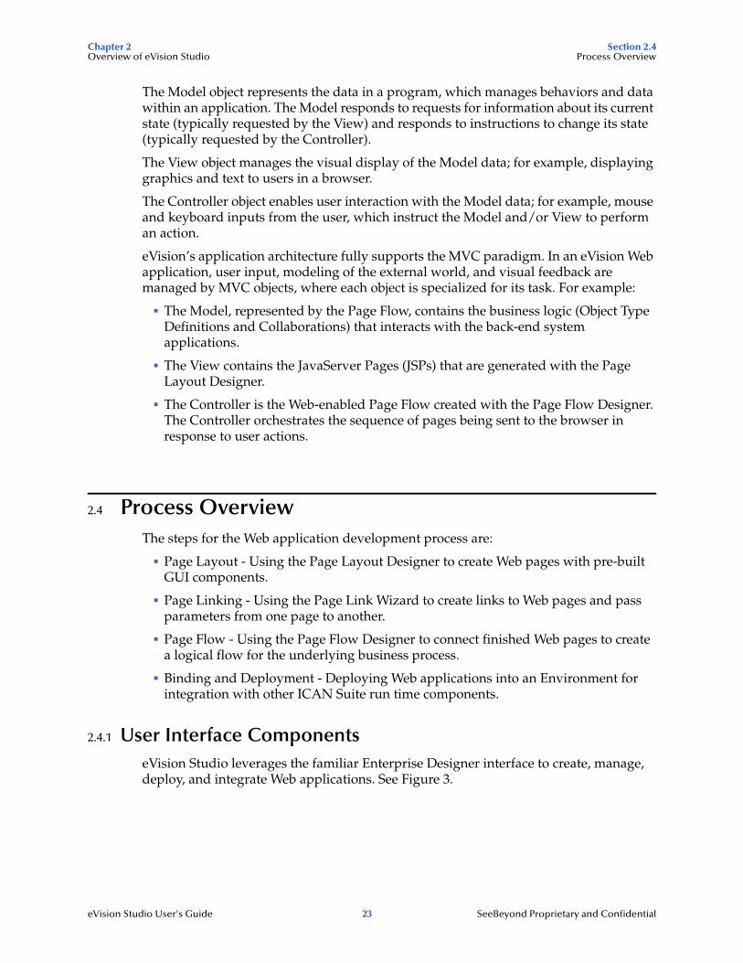
2.4 Process OverviewThe steps for the Web application development process are:
Page Layout - Using the Page Layout Designer to create Web pages with pre-built GUI components.
Page Linking - Using the Page Link Wizard to create links to Web pages and pass parameters from one page to another.
Page Flow - Using the Page Flow Designer to connect finished Web pages to create a logical flow for the underlying business process.
Binding and Deployment - Deploying Web applications into an Environment for integration with other ICAN Suite run time components.
2.4.1 User Interface ComponentseVision Studio leverages the familiar Enterprise Designer interface to create, manage, deploy, and integrate Web applications. See Figure 3.

Chapter 2 Section 2.4Overview of eVision Studio Process Overview
eVision Studio User’s Guide 24 SeeBeyond Proprietary and Confidential
Figure 3 Page Layout Designer in Enterprise Designer
Page Layout Designer
The Page Layout Designer allows you to specify the details of individual pages in the application using familiar drag-and-drop techniques to place GUI components (Web page design objects) onto a design canvas.
The Page Layout Designer provides a comprehensive collection of pre-built GUI components and a Web page editor.
Page Flow DesignerThe Page Flow Designer facilitates the flow of Web-based business activities. The functions include Page Flow modeling, monitoring, and execution, as well as the ability to analyze how data messages flow from page to page.
The Page Flow Designer allows you to lay out the user workflow of a Web application by modeling the high-level, logical, page-by-page flow that users will follow through the Web application to complete a given task (the Page Flow). You can lay out a Web application’s page flow using the Page Flow Designer’s set of graphical modeling tools. At run time, the Page Flow drives the display of eVision Web pages and orchestrates the interactions with back-end systems.

Chapter 2 Section 2.5Overview of eVision Studio UTF-8 Support
eVision Studio User’s Guide 25 SeeBeyond Proprietary and Confidential
Through the deployment of Web pages that are developed with the Page Layout Designer and Page Flow Designer, you can enable enterprise-wide, internal and external access to Web applications across an intranet or the Internet.
2.4.2 Page Flow EngineThe Page Flow Engine orchestrates the system responses to the execution of Web page component code. At run time, the Page Flow Engine executes Page Links, receives and processes user input, and, based on human interaction, moves the viewer from page to page until the underlying process is complete.
2.5 UTF-8 SupporteVision Studio provides support for the UTF-8 encoding scheme during both design time and run time. Therefore, an eVision Web application can include any character set that is supported by UTF-8, including Asian language character sets.

Chapter 3 Section 3.1Installing eVision Studio Supported Operating Systems
eVision Studio User’s Guide 26 SeeBeyond Proprietary and Confidential
Chapter 3
Installing eVision Studio
This chapter describes how to install eVision Studio.
What’s in This Chapter
“Supported Operating Systems” on page 26
“Database Support” on page 26
“Installing the Product Files” on page 27
“IBM AIX Configuration Changes” on page 31
3.1 Supported Operating SystemseVision Studio is available on the following operating systems:
Windows 2000, Windows XP, and Windows Server 2003
HP Tru64 V5.1A and V5.1B
HP-UX 11.0, 11i (PA-RISC), and 11i v2.0 (11.23)
IBM AIX 5.1L and 5.2
Red Hat Enterprise Linux AS 2.1 (Intel x86)
Red Hat Linux 8 (Intel x86)
Sun Solaris 8 and 9
3.2 Database SupportIf desired, you can persist eVision Page Flows using a database. eVision supports the following databases:
Oracle 8.1.7, 9.1, and 9.2
Sybase 12.5
Microsoft SQL Server 2000
IBM DB2 Universal Database 8.1

Chapter 3 Section 3.3Installing eVision Studio Installing the Product Files
eVision Studio User’s Guide 27 SeeBeyond Proprietary and Confidential
3.3 Installing the Product FilesThe installation procedure for eVision Studio is similar to the installation procedure for other ICAN Suite products. You can find general product installation instructions in the SeeBeyond ICAN Suite Installation Guide, which is available from the Enterprise Manager DOCUMENTATION page.
Before you begin, ensure that the Repository is running.
3.3.1. Uploading eVision Studio to the RepositoryeVision Studio consists of two .sar files:
The eVision.sar file contains the product software.
The eVisionDocs.sar file contains the documentation and sample files.
The following procedure must be performed by the Administrator user, or by a user that has been granted a role with upload privileges.
To upload eVision Studio to the Repository
1 Start Internet Explorer.
2 In the Address field, enter http://hostname:portnumber
where
hostname is the TCP/IP host name of the server where the Repository is installed.
portnumber is the base port number of the Repository.
The SeeBeyond Customer Login window of Enterprise Manager appears.
3 Enter your username and password.
4 Click Login.
The Enterprise Manager home page appears.
5 Click the ADMIN tab.
The list of uploaded products appears. At a minimum, the license and eGate must already be uploaded. See Figure 4.

Chapter 3 Section 3.3Installing eVision Studio Installing the Product Files
eVision Studio User’s Guide 28 SeeBeyond Proprietary and Confidential
Figure 4 Enterprise Manager ADMIN Page
6 Click Browse. The Choose file dialog box appears.
7 Select the ProductsManifest.xml file in the top level of the Products - Disc 1 CD-ROM.
8 Click Open.
You are returned to the Enterprise Manager ADMIN page.
9 Click Submit.
The list of products available for uploading appears.
10 On the eVision row, click Browse. The Choose file dialog box appears.
11 Select the eVision.sar file.
12 Click Open.
You are returned to the Enterprise Manager ADMIN page.
13 Click upload now. See Figure 5.
Figure 5 upload now Button
A progress bar indicates the status of the upload.
14 When the upload is finished, click Back to component installation.
eVision now appears in the list of uploaded products.

Chapter 3 Section 3.3Installing eVision Studio Installing the Product Files
eVision Studio User’s Guide 29 SeeBeyond Proprietary and Confidential
15 To upload the eVision Studio documentation and sample files to the Repository, repeat steps 6 through 14 with the following differences:
Use the ProductsManifest.xml file in the Documentation subdirectory.
Upload the eVisionDocs.sar file in the Documentation subdirectory.
The documentation and sample files will be accessible from the Enterprise Manager DOCUMENTATION page.
3.3.2. Updating Enterprise Designer with eVision ModulesThe following procedure adds the eVision modules to Enterprise Designer.
To update Enterprise Designer with eVision modules
1 On the client computer where Enterprise Designer is installed, start Enterprise Designer.
2 On the Tools menu, click Update Center.
The Update Center Wizard appears.
3 Click Next.
Step 2 appears. The items in the Available Updates and New Modules box may differ in your installation. See Figure 6.
Figure 6 Update Center Wizard - Select Modules to Install
4 Click the Add All button.
The items in the Available Updates and New Modules box move to the Include in Install box.
Add All

Chapter 3 Section 3.3Installing eVision Studio Installing the Product Files
eVision Studio User’s Guide 30 SeeBeyond Proprietary and Confidential
5 Click Next. The License Agreement window appears.
6 Click Accept.
The progress bars indicate the status of the download. See Figure 7.
Figure 7 Update Center Wizard - Download Modules
When the download is complete, the message Done appears below the progress bars.
7 Click Next.
8 The Update Center Wizard displays the list of certificates and installed modules.
9 Click Finish. The Restart the IDE dialog box appears.
10 Click OK.
When you log into Enterprise Designer again, you can start using eVision Studio.

Chapter 3 Section 3.4Installing eVision Studio IBM AIX Configuration Changes
eVision Studio User’s Guide 31 SeeBeyond Proprietary and Confidential
3.4 IBM AIX Configuration ChangesIf you using a Repository that is running IBM AIX, you must perform the following procedure in order to monitor eVision Studio Projects in the ICAN Monitor.
To make the configuration changes on an IBM AIX Repository
1 Go to the computer on which the Repository is installed.
2 If the Repository is running, shut it down.
3 Set the DISPLAY environment variable to somehost:0.0, where somehost is the hostname or IP address of one of the computers that will be using the ICAN Monitor. The UNIX user that starts the Repository must perform this step.
Here is an example for the csh shell:
setenv DISPLAY 10.1.192.13:0.0
Here is an example for the sh shell:
DISPLAY=10.1.192.13:0.0export DISPLAY
4 Open the startserver.sh file in the ICAN-root/repository directory.
5 Add the following command to the JAVA_OPTS environment variable:
-Djava.awt.headless=true
6 Save the file.
7 Start the Repository.

eVision Studio User’s Guide 32 SeeBeyond Proprietary and Confidential
Chapter 4
Using the Page Layout Designer
This chapter describes how to use the Page Layout Designer to create eVision Web pages. Each component that you can include in a Page Layout is described. This chapter also describes how to create Page Links.
What’s in This Chapter
“Page Layout Designer Basics” on page 32
“HTML Objects” on page 43
“Form Objects” on page 53
“Extension Objects” on page 64
“Manipulating Objects on the Canvas” on page 71
“Style Sheets” on page 73
“Additional Features” on page 79
“Page Links” on page 82
4.1 Page Layout Designer BasicsThrough the use of drag-and-drop techniques and text-based property sheets, the Page Layout Designer allows you to interactively add graphics, text, and programmatic content to the Web pages in your application.
You drag pre-built components from a component palette and position them on the design canvas. The component’s property sheet is opened automatically. The property sheet allows you to specify attributes, such as the component’s logical name and the user-facing text to be displayed on a Web page.
As you create your Web pages, you can preview the design in your browser at any time.
4.1.1 Adding a Page Layout to a ProjectYou use the Page Layout Wizard to add a Page Layout to a Project.
To add a Page Layout to a Project
1 In the Project Explorer, right-click the Project.
Chapter 4 Section 4.1Using the Page Layout Designer Page Layout Designer Basics
eVision Studio User’s Guide 33 SeeBeyond Proprietary and Confidential
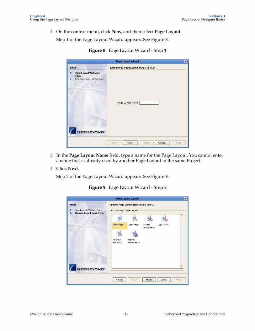
2 On the context menu, click New, and then select Page Layout.
Step 1 of the Page Layout Wizard appears. See Figure 8.
Figure 8 Page Layout Wizard - Step 1
3 In the Page Layout Name field, type a name for the Page Layout. You cannot enter a name that is already used by another Page Layout in the same Project.
4 Click Next.
Step 2 of the Page Layout Wizard appears. See Figure 9.
Figure 9 Page Layout Wizard - Step 2

Chapter 4 Section 4.1Using the Page Layout Designer Page Layout Designer Basics
eVision Studio User’s Guide 34 SeeBeyond Proprietary and Confidential
5 Click one of the Page Layout types based on the Project’s requirements.
Note: Chapter 9, “Authentication and Error Handling” describes the Login Page, Access Denied Error, Login Error, No Such Resource, and Internal Server Error types.
6 Click Finish.
The Page Layout is added to the Project Explorer, and the Page Layout Designer appears with a blank canvas. See Figure 10.
Figure 10 Page Layout Designer

Chapter 4 Section 4.1Using the Page Layout Designer Page Layout Designer Basics
eVision Studio User’s Guide 35 SeeBeyond Proprietary and Confidential
4.1.2 Page Layout Designer ToolbarThe Page Layout Designer toolbar allows you to manipulate the objects that you place on the canvas. See Figure 11.
Figure 11 Page Layout Designer Toolbar
Table 2 describes each tool.
Table 2 Page Layout Designer Tools
Tool Name Purpose
Cut Components Cuts a component from the canvas and places it on the clipboard.
Delete Deletes a component permanently.
Copy Components Copies a component from the canvas and places it on the clipboard.
Paste Components Pastes a component from the clipboard onto the canvas.
Undo Rolls back your most recent input or interaction, and then continues backward up to the last time the layout was saved.
Redo Reverses the most recent rollback, and continues forward up to your last input or interaction.
Left Align Aligns two or more selected components with the left-most component in the selected group.
Right Align Aligns two or more selected components with the right-most component in the selected group.
Center Align Aligns two or more selected components with the center of the canvas (the center of the Web page).
Top Align Aligns two or more selected components with the top-most component in the selected group.

Chapter 4 Section 4.1Using the Page Layout Designer Page Layout Designer Basics
eVision Studio User’s Guide 36 SeeBeyond Proprietary and Confidential
4.1.3 Graphical User Interface ComponentsGraphical User Interface (GUI) components gather input data from the user at run time, and add functions and interactivity to Web pages.
To add a GUI component to the canvas, you select a component from one of the GUI component palettes, drag it onto the canvas, and release the mouse button. The Page Layout Designer provides familiar Web design elements, such as check boxes, text boxes, drop-down lists, graphics containers, horizontal lines, and submit buttons.
GUI components are pre-built combinations of Java classes and JSP code that represent Web interface elements. When you place a GUI component on the canvas, the component’s property sheet is opened automatically. In the property sheet, you add the labeling, functionality, and appearance attributes that you want the component to have when it is presented to the user in a browser.
In the Page Layout Designer, the upper left pane contains the GUI component palettes. The lower left pane contains the property sheets. See Figure 12.
Bottom Align Aligns two or more selected components with the bottom component in the selected group.
Vertical Spacing Creates equal vertical spacing between objects in a group of three or more, based on an averaging algorithm.
Horizontal Spacing Creates equal horizontal spacing between objects in a group of three or more, based on an averaging algorithm.
Edit CSS Launches the Choose CSS to Edit dialog box, which allows you to select an imported style sheet to edit with the eVision Style Editor. For more information, see “Style Sheets” on page 73.
Preview Previews the Page Layout in your browser.
Print Prints the Page Layout.
Tool Name Purpose

Chapter 4 Section 4.1Using the Page Layout Designer Page Layout Designer Basics
eVision Studio User’s Guide 37 SeeBeyond Proprietary and Confidential
Figure 12 GUI Component Palettes and Property Sheet
The Page Layout Designer provides three palettes that allow you to drag and drop GUI components onto the canvas to quickly create a Web page layout from eVision’s collection of pre-built objects.
After you place a GUI component on the canvas, you customize its functional and visual presentation properties in the Properties window.
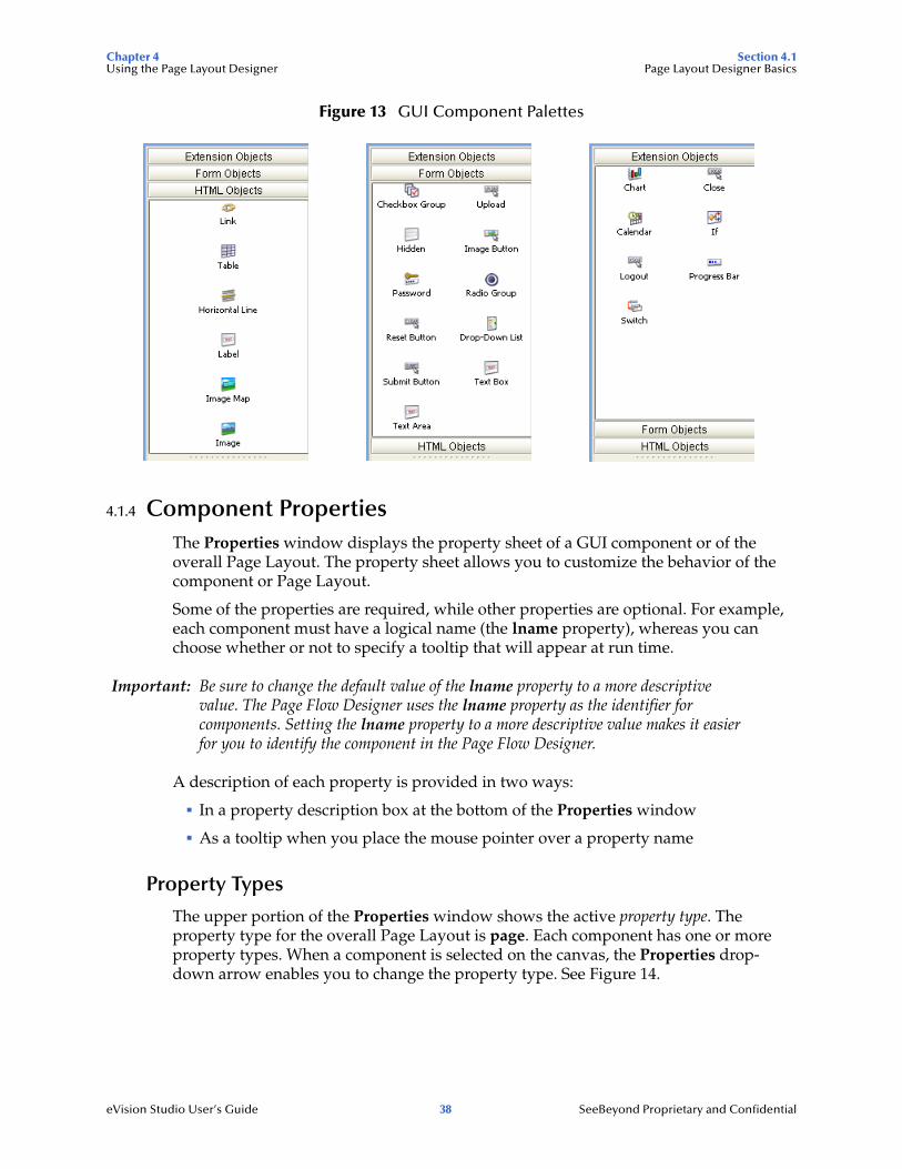
To access the HTML Objects palette, select the HTML Objects title bar. To access the Form Objects palette, select the Form Objects title bar. To access the Extension Objects palette, select the Extension Objects title bar. See Figure 13.
design canvas
GUIcomponentpalettes
propertysheet
Chapter 4 Section 4.1Using the Page Layout Designer Page Layout Designer Basics
eVision Studio User’s Guide 38 SeeBeyond Proprietary and Confidential
Figure 13 GUI Component Palettes
4.1.4 Component PropertiesThe Properties window displays the property sheet of a GUI component or of the overall Page Layout. The property sheet allows you to customize the behavior of the component or Page Layout.
Some of the properties are required, while other properties are optional. For example, each component must have a logical name (the lname property), whereas you can choose whether or not to specify a tooltip that will appear at run time.
Important: Be sure to change the default value of the lname property to a more descriptive value. The Page Flow Designer uses the lname property as the identifier for components. Setting the lname property to a more descriptive value makes it easier for you to identify the component in the Page Flow Designer.
A description of each property is provided in two ways:
In a property description box at the bottom of the Properties window
As a tooltip when you place the mouse pointer over a property name
Property Types
The upper portion of the Properties window shows the active property type. The property type for the overall Page Layout is page. Each component has one or more property types. When a component is selected on the canvas, the Properties drop-down arrow enables you to change the property type. See Figure 14.

Chapter 4 Section 4.1Using the Page Layout Designer Page Layout Designer Basics
eVision Studio User’s Guide 39 SeeBeyond Proprietary and Confidential
Figure 14 Changing the Property Type
Figure 15 shows the default settings of the page property type.
Figure 15 Page Properties
Property Categories
By default, the list of properties is divided into categories. For example, the categories for the page property type are this, IE, and resources. Most of the components have at least the following categories: (id), this, coreAttrs, and events.
Note: The IE category is used for Internet Explorer-specific properties.
You can specify whether to display the list of properties in category or alphabetical format. For category format, click the Categorize icon. For alphabetical format, click the Alphabetize icon. See Figure 16.
Properties drop-down arrow
property type

Chapter 4 Section 4.1Using the Page Layout Designer Page Layout Designer Basics
eVision Studio User’s Guide 40 SeeBeyond Proprietary and Confidential
Figure 16 Category and Alphabetical Formats
Property Values
To set the value for a property, select the property in the left column and then do one of the following in the right column:
Enter a value.
Select an option from the drop-down list.
Click the Command button (...). In the dialog box that appears, enter text or specify options. See Figure 17 and Figure 18.
Figure 17 Command Button
Categorize Alphabetize
Command button

Chapter 4 Section 4.1Using the Page Layout Designer Page Layout Designer Basics
eVision Studio User’s Guide 41 SeeBeyond Proprietary and Confidential
Figure 18 Example Dialog Boxes Displayed With the Command Button
You can restore the original value of a property by clicking the blue, circular arrow in the right column. See Figure 19.
Figure 19 Restoring the Original Value of a Property
4.1.5 Importing ImagesTo make graphic images accessible to your Web page, you must import them into the Project from their location on disk.
To import an image
1 In the Project Explorer, right-click the Project.
2 On the context menu, click New, and then select File.
The Import Files dialog box appears.
Reset arrow

Chapter 4 Section 4.1Using the Page Layout Designer Page Layout Designer Basics
eVision Studio User’s Guide 42 SeeBeyond Proprietary and Confidential
3 Navigate to the directory that contains the file or files that you want to import. See Figure 20.
The image files can reside anywhere on your machine or a network.
Figure 20 Import Files Dialog Box
4 For each file that you want to import, select the file and click Select.
The file names appear in the Selected Import Files box.
5 To remove a file from the list, select the file name in the Selected Import Files box and click Remove.
6 When you are done, click Import.
The images are displayed under your Project in the Project Explorer. See Figure 21.
Figure 21 Imported Images in the Project Explorer

Chapter 4 Section 4.2Using the Page Layout Designer HTML Objects
eVision Studio User’s Guide 43 SeeBeyond Proprietary and Confidential
4.2 HTML ObjectsThe HTML Objects palette allows you to drag and drop HTML-based GUI components onto the Page Layout Designer canvas. HTML objects are represented graphically on a Web page and may or may not have programmatic attributes. Table 3 describes the HTML objects.
Table 3 HTML Objects
Component Name Purpose
Link Creates a link to another location, another page, or an external Web site.
For more information, see “Links” on page 44.
Table Creates a table of rows and columns. Table cells may contain any object from the component palettes. A table can be static or dynamic.
For more information, see “Tables” on page 46 and “Dynamic Tables” on page 47.
Horizontal Line Places a horizontal line on the canvas. Use the Horizontal Line object to create visual separations in your layouts.
For more information, see “Horizontal Lines” on page 52.
Label Creates a field on the canvas to hold HTML (static) text, or can act as a placeholder for dynamic text. You use this component for labels and general information on a page.
For more information, see “Labels” on page 49.
Image Map Allows you to create a “hotspot” on an image that a user can select to perform a link action, linking to another page or an area within the current page. You import the base image the same way that you import a standard graphic image.
For more information, see “Image Maps” on page 51.
Image Holds a static graphic image. When you drag the icon onto the canvas, you are prompted to select the image.
For more information, see “Images” on page 50.

Chapter 4 Section 4.2Using the Page Layout Designer HTML Objects
eVision Studio User’s Guide 44 SeeBeyond Proprietary and Confidential
4.2.1 LinksThe Link component allows you to add an HTML link that points to an internal or external Web site.
Figure 22 shows how a link to the SeeBeyond Web site appears in Preview mode.
Figure 22 Link Example (Preview Mode)
Note: Do not confuse the Link component with Page Links. For information about Page Links, see “Page Links” on page 82.
To create a link
1 From the HTML Objects palette, drag the Link icon onto the canvas.
The link appears. The gold outline represents the outside boundaries.
2 In the Properties sheet, specify the target location of the link:
A In the left column, select the href property.
B In the right column, enter the target location (for example, http://www.seebeyond.com).
3 In the Properties sheet, specify the text that will appear to the user:
A In the left column, select the text property.
B In the right column, replace the default text with the new text (for example, SeeBeyond).
4 You can use the target property to specify how the target location opens. Table 4 describes the valid values.
Table 4 Valid Values of target Property
Value Description
_blank The target location opens in a new window.
_self The target location opens in the same frame.
_parent The target location opens in the parent frame (that is, one level up in the frame hierarchy).
_top The target location opens in the full body of the same window.
Chapter 4 Section 4.2Using the Page Layout Designer HTML Objects
eVision Studio User’s Guide 45 SeeBeyond Proprietary and Confidential
If the value is empty, then the target location opens in the full body of the same window.
5 The default font size is 16. If you want to change the font size, modify the value of the fontSize property.
6 The default font color is blue. If you want to change the font color, modify the value of the fontColor property.
7 For information about the z-index property, see “Moving Overlapping Components in the Z-Direction” on page 72.
8 For information about the class property, see “Applying Classes” on page 78.
9 The title property enables you to enter a tooltip.
10 If you want to add JavaScript that will be executed when the user clicks the link, enter the JavaScript code as the value of the onClick property.
Using JavaScript to Specify Properties of a New Window
You can use the JavaScript method window.open() to specify various properties of a link that opens in a new window.
To specify properties of a new window
1 Ensure that the target property is empty, which is the default setting.
2 In the onClick property, enter the window.open() method:
window.open(this.href,'reassignWindow1','toolbar=no,menubar=no,location=no,scrollbars=no,resizable=yes,status=no,width=600,height=400');return false;
The first parameter must be set to this.href.
The second parameter is an internal name for the window. You can set this parameter to any value. However, if you have multiple links on a page and you want them to open in separate windows at the same time, then the second parameter for each link must be unique.
The third parameter enables you to specify the properties, including the width and height.
Chapter 4 Section 4.2Using the Page Layout Designer HTML Objects
eVision Studio User’s Guide 46 SeeBeyond Proprietary and Confidential
4.2.2 TablesThe Table component enables you to organize information into rows and columns. You can add other GUI components to the table cells.
To create a table
1 From the HTML Objects palette, drag the Table icon onto the canvas.
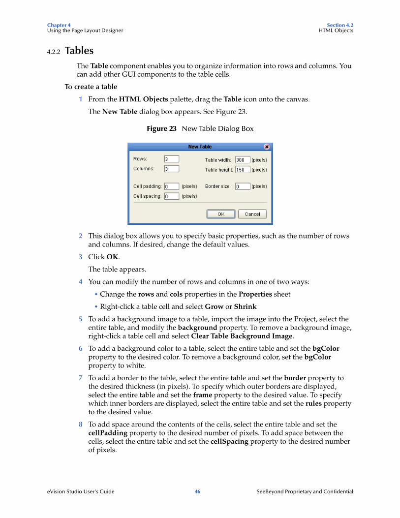
The New Table dialog box appears. See Figure 23.
Figure 23 New Table Dialog Box
2 This dialog box allows you to specify basic properties, such as the number of rows and columns. If desired, change the default values.
3 Click OK.
The table appears.
4 You can modify the number of rows and columns in one of two ways:
Change the rows and cols properties in the Properties sheet
Right-click a table cell and select Grow or Shrink
5 To add a background image to a table, import the image into the Project, select the entire table, and modify the background property. To remove a background image, right-click a table cell and select Clear Table Background Image.
6 To add a background color to a table, select the entire table and set the bgColor property to the desired color. To remove a background color, set the bgColor property to white.
7 To add a border to the table, select the entire table and set the border property to the desired thickness (in pixels). To specify which outer borders are displayed, select the entire table and set the frame property to the desired value. To specify which inner borders are displayed, select the entire table and set the rules property to the desired value.
8 To add space around the contents of the cells, select the entire table and set the cellPadding property to the desired number of pixels. To add space between the cells, select the entire table and set the cellSpacing property to the desired number of pixels.

Chapter 4 Section 4.2Using the Page Layout Designer HTML Objects
eVision Studio User’s Guide 47 SeeBeyond Proprietary and Confidential
9 To specify the width of the table, select the entire table and set the width property to the desired value (in pixels).
10 The summary property enables you to specify alternate text for the table.
11 For information about the class property, see “Applying Classes” on page 78.
12 The title property enables you to enter a tooltip.
13 To remove the contents of a table cell, right-click the cell and select Remove Cell Contents.
Nested Tables
You can add a Table component to a cell of another Table component. The inner table is called a nested table.
If you add a different component (such as a Label component) to a cell of a nested table, you must press and hold the Shift key before resizing the component.
If a nested table is deselected and you want to select it, click slightly outside the boundary of the nested table. A gold outline appears. See Figure 24.
Figure 24 Selecting a Nested Table
4.2.3 Dynamic TablesDynamic tables are created like static tables but with one or more rows designated as “dynamic.” In a dynamic table, the total number of rows, and the row content are undefined. At run time, table rows and content are dynamically generated by a repeating node in a Page Flow.
For information about mapping data into a dynamic table, see “Dynamic Tables” on page 117.
To define a dynamic row in a table
1 Select a cell in the table. The cell will be highlighted in blue.
2 Right-click the cell.
3 On the context menu, select Set As Dynamic Row.
The row will be marked as being dynamic.

Chapter 4 Section 4.2Using the Page Layout Designer HTML Objects
eVision Studio User’s Guide 48 SeeBeyond Proprietary and Confidential
Note: eVision allocates 20 extra pixels to the width of a dynamic table. If a vertical scrollbar is needed at run time, these pixels enable the scrollbar to appear correctly.
Adding Pagination to a Dynamic Table
You can add a “page-forward, page-back”, “page-first, page-last” function to a row or rows in a dynamic table. The pagination feature allows table cell data to be incrementally displayed. For example, if the table is set to read the results of a database query, the table will display the first 10 items returned by query, and allow the user to page forward to the second 10 items, and so on.
All rows are retrieved onto the client side, and the pagination is performed on the client side.
eVision provides the following default image files for the pagination buttons: firstImg.gif, prevImg.gif, nextImg.gif, and lastImg.gif. See Figure 25.
Figure 25 Default Pagination Buttons
If you want to use your own image files, you must first import them into the Project. See “Importing Images” on page 41. You then specify the replacement image files during the following procedure.
To add pagination to a row in a dynamic table
1 Right-click the dynamic row.
2 On the context menu, click Paginate.
3 Click and drag a bounding box around the table.
4 In the Properties sheet, the paginateCount property specifies how many rows the table will accept at a time. The default value is 10. If desired, increase or decrease the value.
5 In the Properties sheet, the firstImg, lastImg, nextImg, and prevImg properties are set to the default image files for the pagination buttons.
If you want to use your own image files, then click a property value, navigate to the image file, and click Open.
Adding Sorting to a Dynamic Table
You can specify that a column in a dynamic table will be sorted. The sort criteria include alphabetic, numeric, and date.
To add sorting to a dynamic table
1 In the row immediately above the dynamic row, click the cell in the column that you want to sort.
2 In the Properties sheet, make sure that the td property type is displayed.
3 Set the value of the sort property to true.
Chapter 4 Section 4.2Using the Page Layout Designer HTML Objects
eVision Studio User’s Guide 49 SeeBeyond Proprietary and Confidential
4 Specify how the column should be sorted by selecting a value for the sortType property. If you want to consider case when sorting alphabetic values, select the alpha value; otherwise, select the alphaIgnoreCase value.
5 Save the Page Layout.
4.2.4 LabelsThe Label component creates a field on the design canvas to hold HTML (static) text, or can act as a placeholder for dynamic text. You use this component for labels and general information on a page.
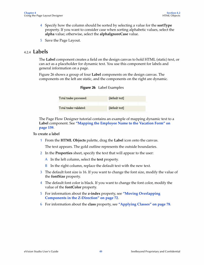
Figure 26 shows a group of four Label components on the design canvas. The components on the left are static, and the components on the right are dynamic.
Figure 26 Label Examples
The Page Flow Designer tutorial contains an example of mapping dynamic text to a Label component. See “Mapping the Employee Name to the Vacation Form” on page 159.
To create a label
1 From the HTML Objects palette, drag the Label icon onto the canvas.
The text appears. The gold outline represents the outside boundaries.
2 In the Properties sheet, specify the text that will appear to the user:
A In the left column, select the text property.
B In the right column, replace the default text with the new text.
3 The default font size is 16. If you want to change the font size, modify the value of the fontSize property.
4 The default font color is black. If you want to change the font color, modify the value of the fontColor property.
5 For information about the z-index property, see “Moving Overlapping Components in the Z-Direction” on page 72.
6 For information about the class property, see “Applying Classes” on page 78.

Chapter 4 Section 4.2Using the Page Layout Designer HTML Objects
eVision Studio User’s Guide 50 SeeBeyond Proprietary and Confidential
4.2.5 ImagesThe Image component holds a static graphic image. When you drag the icon onto the canvas, you are prompted to select the image.
Note: Before you begin, you must import the image into the Project. For more information, see “Importing Images” on page 41.
To create an image
1 From the HTML Objects palette, drag the Image icon onto the canvas.
The Enter value dialog box appears.
Figure 27 Enter value Dialog Box
2 Select the image and click Open.
The image appears on the canvas. The gold outline represents the outside boundaries.
3 If you want to resize the image container, click and drag a highlighted boundary element. The shape of the bidirectional arrow cursor indicates which way the container will be resized.
If you want to move the image container, click the container in the center (away from the edges) and drag it to the new location.
4 The alt property enables you to specify alternate text for the image.
5 The border property enables you to add a border to the image. The default value of 0 indicates the absence of a border. The value is measured in pixels.
6 The hSpace property enables you to add space to the left and right of the image. The vSpace property enables you to add space above and below the image. The values are measured in pixels.
7 The height property enables you to override the default height of the image. The width property enables you to override the default width of the image. The values are measured in pixels.

Chapter 4 Section 4.2Using the Page Layout Designer HTML Objects
eVision Studio User’s Guide 51 SeeBeyond Proprietary and Confidential
8 The src property enables you to select a different image.
9 For information about the z-index property, see “Moving Overlapping Components in the Z-Direction” on page 72.
10 If you want the My Pictures image toolbar to appear when the mouse pointer is placed over the image, set the galleryImg property to yes. This property is specific to Internet Explorer.
Note: The page property type includes a property called imageToolbar, which specifies the behavior of the My Pictures image toolbar for the overall Page Layout. Setting the galleryImg property overrides the imageToolbar setting.
11 For information about the class property, see “Applying Classes” on page 78.
12 The title property enables you to enter a tooltip.
4.2.6 Image MapsYou create an image map by bounding an area of an image and attaching linking code to the area within the boundary. Users can then click the area to execute the code. You can define an image map to link to an external Web site, or to link to another page in the Page Flow.
Note: Before you begin, you must import the image into the Project. For more information, see “Importing Images” on page 41.
When you work with image maps, the following tools are added to the Page Layout Designer toolbar:
The Select Link Area tool highlights the link area.
The Select Image Map tool highlights the image.
Only one of these tools is enabled at a time.
To create an image map
1 From the HTML Objects palette, drag the Image Map icon onto the canvas.
The Enter value dialog box appears.
2 Select the image for the image map and click Open.
The image appears on the canvas. The gold outline represents the outside boundaries.
3 If you want to resize the image container, click and drag a highlighted boundary element. The shape of the bidirectional arrow cursor indicates which way the container will be resized.
If you want to move the image container, click the container in the center (away from the edges) and drag it to the new location.
4 To add a link to the image, do one of the following:

Chapter 4 Section 4.2Using the Page Layout Designer HTML Objects
eVision Studio User’s Guide 52 SeeBeyond Proprietary and Confidential
In the Project Explorer tree, drag a Page Link and drop it onto the image. This link has predefined parameters and a target location.
From the HTML Objects palette, drag the Link icon onto the image. This link requires that you specify link parameters and a target location.
When you drop a link onto the image, a rectangle appears. This is the link area.
5 In the Properties sheet, specify the target location of the link area (if necessary):
A In the left column, select the href property.
B In the right column, enter the target location (for example, http://www.seebeyond.com).
6 If you want to resize the link area, click and slowly drag a highlighted boundary element.
If you want to move the link area, click the link area in the center (away from the edges) and drag it to the new location.
You can also resize and move the link area by manually entering the coordinates in the Properties sheet. In the left column, click the coords property. In the right column, change the value.
If the link area that you are trying to size to is too small, right-click the image and choose Set Link Area to Image Size.
7 If desired, create additional link areas in the image.
To test an image map
1 On the Page Layout Designer toolbar, click the Preview icon.
In the preview image, when you move the pointer over the mapped area, the cursor changes to the “hand” icon.
2 Click the defined image area to execute the link code.
4.2.7 Horizontal LinesThe Horizontal Line component enables you to create an HTML horizontal rule.
To create a horizontal line
1 From the HTML Objects palette, drag the Horizontal Line icon onto the canvas.
2 The line is initially of a fixed length. To extend the line, place the pointer on the end that you want to change (right or left, up or down). The pointer changes to a resize arrow (<-->). Drag the line end to modify the length. The bidirectional arrow cursor is dual-purpose. You can add thickness to the line as well as adjust the length. Drag the line end carefully, taking care not to add thickness to the line.
3 To move the line, click the line’s mid-point (avoid the end points) and drag it to a new location.
4 The default font color is black. If you want to change the font color, modify the value of the color property.

Chapter 4 Section 4.3Using the Page Layout Designer Form Objects
eVision Studio User’s Guide 53 SeeBeyond Proprietary and Confidential
5 For information about the z-index property, see “Moving Overlapping Components in the Z-Direction” on page 72.
6 For information about the class property, see “Applying Classes” on page 78.
4.3 Form ObjectsForm Objects are pre-built combinations of Java classes and JSP code representing Web interface entities. These objects allow users to communicate with Page Flows in the run-time environment. Table 5 describes the form objects.
Table 5 Form Objects
Component Name Purpose
Checkbox Group Creates a group of check boxes. Indicates inclusive user selection at run time. You can create multiple check boxes within a group.
For more information, see “Check Box Groups” on page 55.
Upload Allows the user to upload files and data to an application.
For more information, see “Upload Components” on page 62.
Hidden Creates a hidden text field (a text field that is hidden from users at run time), which can be used to pass session information to another page without being visible to users.
For more information, see “Hidden Elements” on page 63.
Image Button Creates an image “hotspot” that the user can click to perform an action, such as launching an application or jumping to another internal Web page or an external Web site.
For more information, see “Image Buttons” on page 59.
Password Creates a password input box with bullets that mask the password.
For more information, see “Password Boxes” on page 62.

Chapter 4 Section 4.3Using the Page Layout Designer Form Objects
eVision Studio User’s Guide 54 SeeBeyond Proprietary and Confidential
Radio Group Switches an attribute or condition on or off. You can create multiple buttons in a group.
Note: The value property cannot be empty. This object requires that a value be assigned in order to pass the true/false condition.
For more information, see “Radio Groups” on page 56.
Reset Button Allows the user to cancel an operation or reset values to a default condition.
For more information, see “Reset Buttons” on page 63.
Drop-Down List Allows the user to select an entry from a drop-down list. You can create multiple entries on a list.
For more information, see “Drop-Down Lists” on page 57.
Submit Button Allows the user to launch an operation or submit text to the application. Passes accumulated values to the ICAN system.
For more information, see “Submit Buttons” on page 58.
Text Box Allows the user to type text that will be displayed on the Web page surrounded by a bounding box.
For more information, see “Text Boxes” on page 60.
Text Area Allows the user to type an extensive body of text and place it anywhere on the Web page without disturbing formatting.
For more information, see “Text Areas” on page 61.
Component Name Purpose

Chapter 4 Section 4.3Using the Page Layout Designer Form Objects
eVision Studio User’s Guide 55 SeeBeyond Proprietary and Confidential
4.3.1 Check Box GroupsThe Checkbox Group component allows you to create a group of check boxes. You specify the label and value for each check box.
Figure 28 Checkbox Group Example (Preview Mode)
To create a check box group
1 From the Form Objects palette, drag the Checkbox Group component onto the canvas.
2 Right-click the component.
3 On the context menu, select Edit Options.
The Edit Options dialog box appears.
4 Select a Label field and type a label.
The label will be displayed next to the check box at run time.
5 In the Value field, type a value.
The value will be submitted when the user checks the box at run time.
6 To add additional check boxes to the group, click Add and repeat the previous steps.
7 Click OK.
8 If you want to ensure that the user selects at least one check box in the group, set the validationType property to isChecked. The validationMsg property specifies the error message that appears when the validation does not succeed.
9 For information about the z-index property, see “Moving Overlapping Components in the Z-Direction” on page 72.
Note: You can drag a Checkbox Group component into a table cell and make the table row dynamic. At run time, the component can be modified by external sources to generate additional cells containing check boxes.

Chapter 4 Section 4.3Using the Page Layout Designer Form Objects
eVision Studio User’s Guide 56 SeeBeyond Proprietary and Confidential
4.3.2 Radio GroupsThe Radio Group component allows you to create a group of radio buttons. You specify the label and value for each radio button.
Figure 29 Radio Group Example (Preview Mode)
To create a radio group
1 From the Form Objects palette, drag the Radio Group component onto the canvas.
2 Right-click the component.
3 On the context menu, select Edit Options.
The Edit Options dialog box appears.
4 Select a Label field and type a label.
The label will be displayed next to the button at run time.
5 In the Value field, type a value.
This value will be submitted when the user clicks the button at run time.
6 To create additional buttons in the group, click Add and repeat the previous steps.
7 Click OK.
8 If you want to ensure that the user makes a selection, set the validationType property to isChecked. The validationMsg property specifies the error message that appears when the validation does not succeed.
9 For information about the z-index property, see “Moving Overlapping Components in the Z-Direction” on page 72.
Note: You can drag a Radio Group component into a table cell and make the table row dynamic. At run time, the component can be modified by external sources to generate additional cells containing radio buttons.
Chapter 4 Section 4.3Using the Page Layout Designer Form Objects
eVision Studio User’s Guide 57 SeeBeyond Proprietary and Confidential
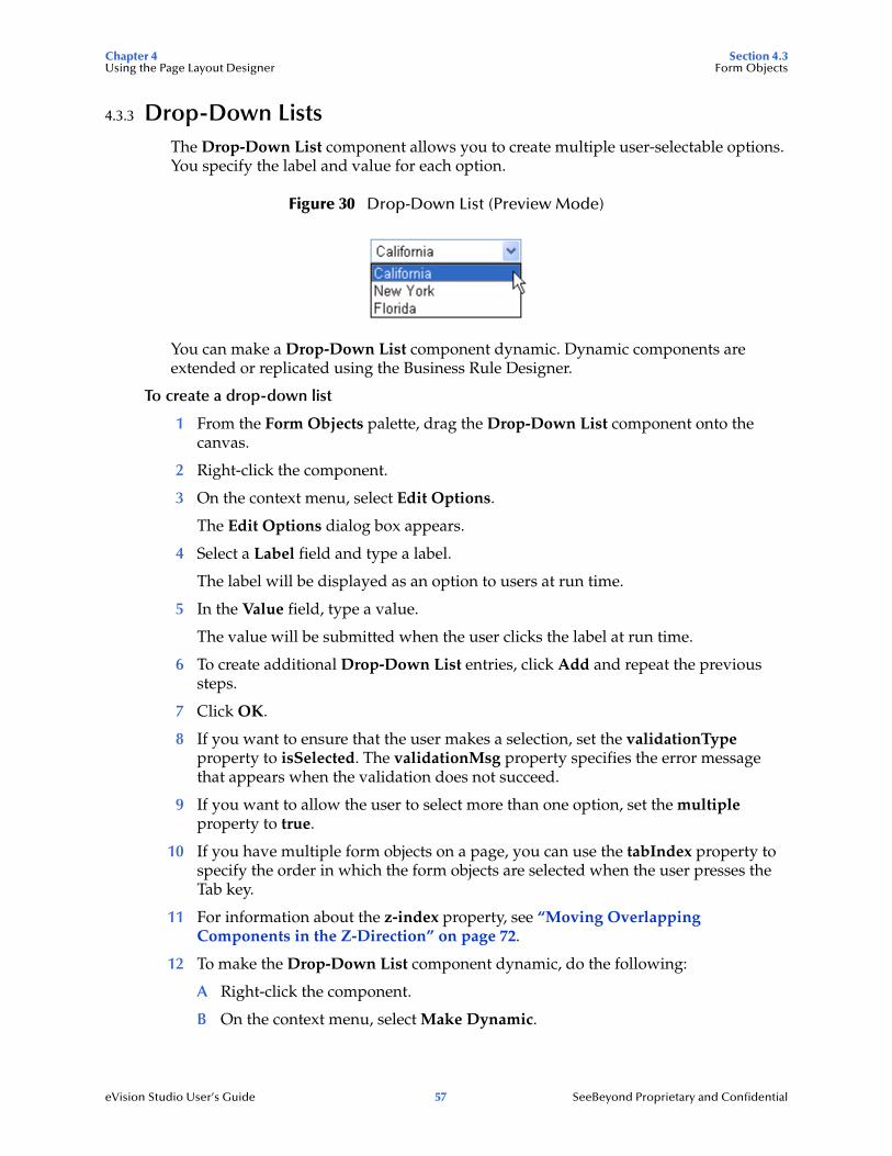
4.3.3 Drop-Down ListsThe Drop-Down List component allows you to create multiple user-selectable options. You specify the label and value for each option.
Figure 30 Drop-Down List (Preview Mode)
You can make a Drop-Down List component dynamic. Dynamic components are extended or replicated using the Business Rule Designer.
To create a drop-down list
1 From the Form Objects palette, drag the Drop-Down List component onto the canvas.
2 Right-click the component.
3 On the context menu, select Edit Options.
The Edit Options dialog box appears.
4 Select a Label field and type a label.
The label will be displayed as an option to users at run time.
5 In the Value field, type a value.
The value will be submitted when the user clicks the label at run time.
6 To create additional Drop-Down List entries, click Add and repeat the previous steps.
7 Click OK.
8 If you want to ensure that the user makes a selection, set the validationType property to isSelected. The validationMsg property specifies the error message that appears when the validation does not succeed.
9 If you want to allow the user to select more than one option, set the multiple property to true.
10 If you have multiple form objects on a page, you can use the tabIndex property to specify the order in which the form objects are selected when the user presses the Tab key.
11 For information about the z-index property, see “Moving Overlapping Components in the Z-Direction” on page 72.
12 To make the Drop-Down List component dynamic, do the following:
A Right-click the component.
B On the context menu, select Make Dynamic.

Chapter 4 Section 4.3Using the Page Layout Designer Form Objects
eVision Studio User’s Guide 58 SeeBeyond Proprietary and Confidential
At run time, a dynamic Drop-Down List component can be extended with additional labels and values generated by external sources at run time. The Edit Options menu is disabled when you select Make Dynamic.
Note: The values of dynamic components do not appear when you click the Preview icon, because the values are assigned at run time.
4.3.4 Submit ButtonsThe Submit Button component enables the user to send form data on the Page Layout to the Web application.
To create a submit button
1 From the Form Objects palette, drag the Submit Button component onto the canvas.
2 The value property specifies the text that appears on the button. If desired, change the default value.
3 For information about the z-index property, see “Moving Overlapping Components in the Z-Direction” on page 72.
4 For information about the class property, see “Applying Classes” on page 78.
5 The title property enables you to enter a tooltip.
6 If you have multiple form objects on a page, you can use the tabIndex property to specify the order in which the form objects are selected when the user presses the Tab key.
Back-End System Scenario
The Submit Button component is often used for a scenario in which you want to send data entered by the user to a back-end system.
To help ensure that the data is successfully sent to the back-end system, SeeBeyond recommends that you create two Page Layouts.
The first Page Layout contains the Submit Button component.
The second Page Layout is a confirmation page. Add a message such as the following:
Your data has been submitted.
Below the message, add a Close button, which enables the user to close the browser window.
If the Page Layouts are located within a sub-process, see “Close Buttons” on page 68 for information about the behavior of the Close button.

Chapter 4 Section 4.3Using the Page Layout Designer Form Objects
eVision Studio User’s Guide 59 SeeBeyond Proprietary and Confidential
4.3.5 Image ButtonsThe Image Button component enables you to create a graphical submit button.
Note: Before you begin, you must import the image into the Project. For more information, see “Importing Images” on page 41.
To create an image button
1 From the Form Objects palette, drag the Image Button component onto the canvas.
The Enter value dialog box appears.
Figure 31 Enter value Dialog Box
2 Select the image and click Open.
The image appears on the canvas. The gold outline represents the outside boundaries.
3 If you want to resize the image container, click and drag a highlighted boundary element. The shape of the bidirectional arrow cursor indicates which way the container will be resized.
If you want to move the image container, click the container in the center (away from the edges) and drag it to the new location.
4 The value property specifies the value that is submitted.
5 For information about the z-index property, see “Moving Overlapping Components in the Z-Direction” on page 72.
6 For information about the class property, see “Applying Classes” on page 78.
7 The title property enables you to enter a tooltip.

Chapter 4 Section 4.3Using the Page Layout Designer Form Objects
eVision Studio User’s Guide 60 SeeBeyond Proprietary and Confidential
4.3.6 Text BoxesThe Text Box component allows the user to enter text that will be displayed on the Web page surrounded by a box. This component supports one line of text. If you want the user to be able to enter more than one line of text, then create a Text Area component.
In the Page Layout Designer tutorial, you use this component to create the input fields where the user enters the employee name and number of hours worked.
To create a text box
1 From the Form Objects palette, drag the Text Box component onto the canvas.
2 To change the default text, modify the value of the value property.
3 If you want to prevent users from editing the text box, set the readOnly property to true.
4 For information about the z-index property, see “Moving Overlapping Components in the Z-Direction” on page 72.
5 For information about the class property, see “Applying Classes” on page 78.
6 The title property enables you to enter a tooltip.
7 If you have multiple form objects on a page, you can use the tabIndex property to specify the order in which the form objects are selected when the user presses the Tab key.
8 The validationType property enables you to validate the text that the user enters. For some of the functions, you must enter an argument in the validationArgs property. For all of the functions, the validationMsg property enables you to specify the error message that appears when the text is invalid. If you do not want an empty text box to be validated, then set the validateEmpty property to false.
Table 6 describes the validation functions:
Table 6 Validation Functions
Function Description
noValidation Does not validate the text.
isRequired Ensures that the text is not blank.
isMinimumLength Ensures that the text is a minimum number of characters. Enter the number in the validationArgs property.
isMaximumLength Ensures that the text does not exceed a maximum number of characters. Enter the number in the validationArgs property.
isValidInt Ensures that the text is a valid whole number (positive or negative).
isValidAmount Ensures that the text is a valid number (positive or negative) with two decimal places. For example, the number 100.00 is valid, but the number 100 is not.
isValidEmail Ensures that the text is an e-mail address in a valid format. The function does not ensure that the e-mail address actually exists.
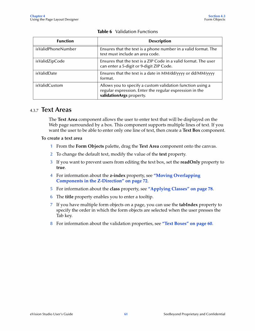
Chapter 4 Section 4.3Using the Page Layout Designer Form Objects
eVision Studio User’s Guide 61 SeeBeyond Proprietary and Confidential
4.3.7 Text AreasThe Text Area component allows the user to enter text that will be displayed on the Web page surrounded by a box. This component supports multiple lines of text. If you want the user to be able to enter only one line of text, then create a Text Box component.
To create a text area
1 From the Form Objects palette, drag the Text Area component onto the canvas.
2 To change the default text, modify the value of the text property.
3 If you want to prevent users from editing the text box, set the readOnly property to true.
4 For information about the z-index property, see “Moving Overlapping Components in the Z-Direction” on page 72.
5 For information about the class property, see “Applying Classes” on page 78.
6 The title property enables you to enter a tooltip.
7 If you have multiple form objects on a page, you can use the tabIndex property to specify the order in which the form objects are selected when the user presses the Tab key.
8 For information about the validation properties, see “Text Boxes” on page 60.
isValidPhoneNumber Ensures that the text is a phone number in a valid format. The text must include an area code.
isValidZipCode Ensures that the text is a ZIP Code in a valid format. The user can enter a 5-digit or 9-digit ZIP Code.
isValidDate Ensures that the text is a date in MM/dd/yyyy or dd/MM/yyyy format.
isValidCustom Allows you to specify a custom validation function using a regular expression. Enter the regular expression in the validationArgs property.
Table 6 Validation Functions
Function Description

Chapter 4 Section 4.3Using the Page Layout Designer Form Objects
eVision Studio User’s Guide 62 SeeBeyond Proprietary and Confidential
4.3.8 Upload ComponentsThe Upload component allows the user to upload a file to the Web application. The component consists of a text box and a browse button.
The user can specify the file in one of two ways:
Enter the fully qualified name of the file in the text box
Click the browse button to navigate the file system and select the file.
To create an upload component
1 From the Form Objects palette, drag the Upload component onto the canvas.
2 For information about the z-index property, see “Moving Overlapping Components in the Z-Direction” on page 72.
3 For information about the class property, see “Applying Classes” on page 78.
4 The title property enables you to enter a tooltip.
5 If you have multiple form objects on a page, you can use the tabIndex property to specify the order in which the form objects are selected when the user presses the Tab key.
4.3.9 Password BoxesThe Password component enables the user to enter a password into a text box. The password is masked with bullets.
To create a password box
1 From the Form Objects palette, drag the Password component onto the canvas.
2 By default, the password is not validated. If you want to validate the password, set the validationType property to the appropriate function. For example, you can ensure that the password is numeric by setting this property to isValidInt.
The validationMsg property specifies the error message that appears when the password is invalid. For example, if you are ensuring that the password is numeric, you could set this property to Please enter a numeric password.
3 For information about the z-index property, see “Moving Overlapping Components in the Z-Direction” on page 72.
4 For information about the class property, see “Applying Classes” on page 78.
5 The title property enables you to enter a tooltip.
6 If you have multiple form objects on a page, you can use the tabIndex property to specify the order in which the form objects are selected when the user presses the Tab key.

Chapter 4 Section 4.3Using the Page Layout Designer Form Objects
eVision Studio User’s Guide 63 SeeBeyond Proprietary and Confidential
4.3.10 Hidden ElementsThe Hidden component creates a hidden text box in the Page Layout. You can use this component to pass session information to another page without being visible to users. The component appears on the design canvas, but not in Preview mode or at run time.
To create a hidden element
1 From the Form Objects palette, drag the Hidden component onto the canvas.
2 The value property specifies the value that is submitted.
3 For information about the class property, see “Applying Classes” on page 78.
4 The title property enables you to enter a tooltip.
4.3.11 Reset ButtonsThe Reset Button component allows the user to change the settings of other form objects on the same page to their original values.
For example, assume that the Calendar component initially has no value in the text box. The user clicks the drop-down arrow and selects the date 07/14/2004. If the user clicks the Reset Button component, the date is removed from the text box.
To create a Reset button
1 From the Form Objects palette, drag the Reset Button component onto the canvas.
2 The value property specifies the text that appears on the button. If desired, change the default value.
3 For information about the z-index property, see “Moving Overlapping Components in the Z-Direction” on page 72.
4 For information about the class property, see “Applying Classes” on page 78.
5 The title property enables you to enter a tooltip.
6 If you have multiple form objects on a page, you can use the tabIndex property to specify the order in which the form objects are selected when the user presses the Tab key.

Chapter 4 Section 4.4Using the Page Layout Designer Extension Objects
eVision Studio User’s Guide 64 SeeBeyond Proprietary and Confidential
4.4 Extension ObjectsThe Extension Objects palette contains components that do not fall into the HTML or Form categories. Table 7 describes the extension objects.
Table 7 Extension Objects
Component Name Purpose
Chart Creates a two-dimensional chart. eVision provides a variety of predefined chart types, including area charts, bar charts, line charts, and pie charts.
For more information, see Chapter 8, “Creating Charts”.
Close Allows the user to close the browser window. The Page Flow is automatically ended.
For more information, see “Close Buttons” on page 68.
Calendar Adds a calendar under a drop-down arrow. On a Web page, selecting a date on the calendar object populates an attached text box with the selected date.
For more information, see “Calendars” on page 66.
If Allows you to conditionally display an area of a Page Layout.
For more information, see “If and Switch” on page 65.
Logout Allows the user to exit the eVision Web application. Clicking this button returns the user to the beginning of the Page Flow.
For more information, see “Logout Buttons” on page 69.
Progress Bar Creates a progress bar that allows the user to monitor the progress of a particular operation on a Web page.
For more information, see “Progress Bars” on page 67.
Switch Allows you to conditionally display an area of a Page Layout.
For more information, see “If and Switch” on page 65.

Chapter 4 Section 4.4Using the Page Layout Designer Extension Objects
eVision Studio User’s Guide 65 SeeBeyond Proprietary and Confidential
4.4.1 If and SwitchThe If component allows you to conditionally display an area of a Page Layout. After you drag the component onto the canvas, you add content. When the value property is set to true, the content inside this component (for example, a company logo) will appear at run time. When the value property is set to false, the content will not appear at run time. You can set this property statically in the Page Layout Designer, or dynamically in the Page Flow Designer.
You can resize the If component horizontally or vertically using the mouse.
The Switch component also allows you to conditionally display an area of a Page Layout. You specify two or more cases and add different content to each case.
To add a case, right-click the component and select Add Case. See Figure 32.
Figure 32 Adding a Case to the Switch Component
The Switch component contains three property types:
For a non-default case, the case property of the case property type enables you to change the name of the case.
The value property of the switch property type specifies the name of the case that appears at run time. You can set this property statically in the Page Layout Designer, or dynamically in the Page Flow Designer.
You can resize the Switch component horizontally or vertically using the mouse.
To remove a case, right-click the case and select Remove Case. You cannot remove the default case.
Table 8 Switch Property Types
Property Type Description
switch Properties for the overall component.
default Properties for the default case.
case Properties for a non-default case.
new case

Chapter 4 Section 4.4Using the Page Layout Designer Extension Objects
eVision Studio User’s Guide 66 SeeBeyond Proprietary and Confidential
4.4.2 CalendarsThe Calendar component enables the user to select a calendar date. The component consists of a text box and a drop-down arrow.
When the user clicks the drop-down arrow, the current month appears. The user can scroll back to previous months and forward to succeeding months. When the user clicks a date, the date appears in the text box.
Figure 33 shows how this component appears in Preview mode.
Figure 33 Calendar Example (Preview Mode)
To create a calendar
1 From the Extension Objects palette, drag the Calendar component onto the canvas.
2 By default, the selected date appears in MM/dd/yyyy format. The validationArgs property enables you to change the format to dd/MM/yyyy.
The validationMsg property specifies the error message that appears when the user enters an invalid date. If desired, change the default error message.
3 For information about the z-index property, see “Moving Overlapping Components in the Z-Direction” on page 72.
4 For information about the class property, see “Applying Classes” on page 78.
5 The title property enables you to enter a tooltip.
6 If you have multiple form objects on a page, you can use the tabIndex property to specify the order in which the form objects are selected when the user presses the Tab key.

Chapter 4 Section 4.4Using the Page Layout Designer Extension Objects
eVision Studio User’s Guide 67 SeeBeyond Proprietary and Confidential
4.4.3 Progress BarsThe Progress Bar component enables you to illustrate the percentage of completion of an action. The progress bar has a horizontal orientation. Figure 34 shows how this component appears in Preview mode.
Figure 34 Progress Bar Example (Preview Mode)
You specify the data for the progress bar in the Page Flow Designer, rather than the Page Layout Designer.
To create a progress bar
1 From the Extension Objects palette, drag the Progress Bar component onto the canvas.
2 This component has the following color-related properties. If desired, change the default color of one or more properties.
The backgroundColor property sets the color of the area in which the progress indicator expands.
The borderColor property sets the color of the outer border.
The progressColor property sets the color of the progress indicator.
3 You do not need to modify the percentComplete property in the Page Layout Designer. When you place the Page Layout in a Page Flow, create a business rule to specify the data that the progress bar will measure.
For example, assume that Page Layout 1 contains a text box and Page Layout 2 contains a progress bar. Create a business rule between the Page Layouts. In the Business Rule Designer, map the value node of the text box to the percentComplete node of the progress bar.
Chapter 6, “Using the Page Flow Designer” describes how to use the Business Rule Designer.
4 Set the Page Layout in which the progress bar is located to automatically refresh after a brief period of time (for example, 2 seconds). “Automatically Refreshing Page Layouts” on page 80 describes how to perform this task.
progress indicator
border
background

Chapter 4 Section 4.4Using the Page Layout Designer Extension Objects
eVision Studio User’s Guide 68 SeeBeyond Proprietary and Confidential
4.4.4 Close ButtonsWhen a user presses the Close button, eVision sends an exception for pending requests to the Page Flow, invalidates the session, and closes the browser.
If you want the Page Flow to continue after the user presses the Close button, then you must catch the exception.
Figure 35 shows a Page Flow in which the second Page Layout contains a Close button. The second Page Layout is followed by a long-running activity. The Page Flow includes a Catch Named Exception element, which catches the exception sent by the second Page Layout and performs appropriate business logic.
Figure 35 Catching Named Exception in Page Flow with Close Button
For more information about exception handling, see the eInsight Business Process Manager User’s Guide.
Note: If a session timeout occurs, eVision sends a page exception and invalidates the session. By default, the session timeout is 60 minutes. “Linking Each Service to a Web Connector” on page 134 describes how to change the default value.
To create a close button
1 From the Extension Objects palette, drag the Close icon onto the canvas.
The Close button appears. The gold outline represents the outside boundaries of the button.
2 If you want to change the default image, do the following:
A Import the image that you want to use into your Project. For more information, see Importing Images on page 41.
B In the Properties sheet, click the src property.
C Place your cursor over the existing value and click the Command button (...). The Enter value for “src” dialog box appears.
Chapter 4 Section 4.4Using the Page Layout Designer Extension Objects
eVision Studio User’s Guide 69 SeeBeyond Proprietary and Confidential
D Navigate to the image that you want to use.
E Click Open.
3 For information about the z-index property, see “Moving Overlapping Components in the Z-Direction” on page 72.
4 If you want the My Pictures image toolbar to appear when the mouse pointer is placed over the Close button, set the galleryImg property to yes. This property is specific to Internet Explorer.
Note: The page property type includes a property called imageToolbar, which specifies the behavior of the My Pictures image toolbar for the overall Page Layout. Setting the galleryImg property overrides the imageToolbar setting.
5 For information about the class property, see “Applying Classes” on page 78.
4.4.5 Logout ButtonsWhen a user presses the Logout button, eVision sends an exception for pending requests to the Page Flow, invalidates the session, and returns the user to the beginning of the Page Flow.
If you want the Page Flow to continue after the user presses the Logout button, then you must catch the exception. For information about exception handling, see the eInsight Business Process Manager User’s Guide.
Note: If a session timeout occurs, eVision sends a page exception and invalidates the session. By default, the session timeout is 60 minutes. “Linking Each Service to a Web Connector” on page 134 describes how to change the default value.
To create a logout button
1 From the Extension Objects palette, drag the Logout icon onto the canvas.
The Logout button appears. The gold outline represents the outside boundaries of the button.
2 If you want to change the default image, do the following:
A Import the image that you want to use into your Project. For more information, see Importing Images on page 41.
B In the Properties sheet, click the src property.
C Place your cursor over the existing value and click the Command button (...). The Enter value for “src” dialog box appears.
D Navigate to the image that you want to use.
E Click Open.
3 For information about the z-index property, see “Moving Overlapping Components in the Z-Direction” on page 72.

Chapter 4 Section 4.4Using the Page Layout Designer Extension Objects
eVision Studio User’s Guide 70 SeeBeyond Proprietary and Confidential
4 If you want the My Pictures image toolbar to appear when the mouse pointer is placed over the Logout button, set the galleryImg property to yes. This property is specific to Internet Explorer.
Note: The page property type includes a property called imageToolbar, which specifies the behavior of the My Pictures image toolbar for the overall Page Layout. Setting the galleryImg property overrides the imageToolbar setting.
5 For information about the class property, see “Applying Classes” on page 78.
Chapter 4 Section 4.5Using the Page Layout Designer Manipulating Objects on the Canvas
eVision Studio User’s Guide 71 SeeBeyond Proprietary and Confidential
4.5 Manipulating Objects on the CanvasThis section describes how to move objects, resize objects, and set the z-order of objects.
4.5.1 Moving and Resizing ObjectsWhen you are viewing a page in Preview mode, some components may not be located exactly where you want them, or a component may be too large or too small. For example, if two horizontal lines are not of equal length, and they are supposed to be separate but identical, this may detract from the overall composition of the Page Layout. This section describes the various ways that you can manually move and resize page components.
Moving a Single Object
To move a single object to any location, select the object. When the object is active, it is highlighted with a gold border. You can click-and-drag the object to any location on the page using the mouse. When the object is where you want it, release the mouse button.
You can also move an object using the arrow keys on your computer keyboard. When the object is where you want it, click the canvas in a blank area.
Moving a Group of Objects
To choose two or more objects to be moved simultaneously, do one of the following:
Select the canvas in a blank area adjacent to the objects that you want to move, and drag the cursor over the objects. Your mouse movement traces a bounding box for visual reference. You can surround the objects that you want to move, or more simply, one edge of the bounding box must intersect with an object to add it to the group.
Press and hold the Shift key on your computer and sequentially select the objects that you want to move.
When the objects are selected, click-and-drag one of the objects and the others will follow.
You can also move a group of objects using the arrow keys on your computer keyboard. When the objects are where you want them, click the canvas in a blank area.
Resizing Objects
You can resize objects vertically or horizontally, depending on the attributes of the object.
Select the object or objects as described in “Moving a Single Object” on page 71 and “Moving a Group of Objects” on page 71. Move the pointer over a border of the object. The pointer changes to a bidirectional arrow. Click-and-drag the border to resize the object.
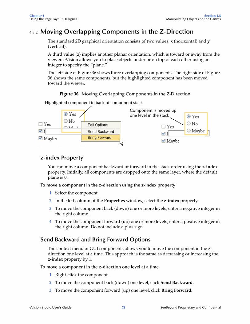
Chapter 4 Section 4.5Using the Page Layout Designer Manipulating Objects on the Canvas
eVision Studio User’s Guide 72 SeeBeyond Proprietary and Confidential
4.5.2 Moving Overlapping Components in the Z-DirectionThe standard 2D graphical orientation consists of two values: x (horizontal) and y (vertical).
A third value (z) implies another planar orientation, which is toward or away from the viewer. eVision allows you to place objects under or on top of each other using an integer to specify the “plane.”
The left side of Figure 36 shows three overlapping components. The right side of Figure 36 shows the same components, but the highlighted component has been moved toward the viewer.
Figure 36 Moving Overlapping Components in the Z-Direction
z-index Property
You can move a component backward or forward in the stack order using the z-index property. Initially, all components are dropped onto the same layer, where the default plane is 0.
To move a component in the z-direction using the z-index property
1 Select the component.
2 In the left column of the Properties window, select the z-index property.
3 To move the component back (down) one or more levels, enter a negative integer in the right column.
4 To move the component forward (up) one or more levels, enter a positive integer in the right column. Do not include a plus sign.
Send Backward and Bring Forward Options
The context menu of GUI components allows you to move the component in the z-direction one level at a time. This approach is the same as decreasing or increasing the z-index property by 1.
To move a component in the z-direction one level at a time
1 Right-click the component.
2 To move the component back (down) one level, click Send Backward.
3 To move the component forward (up) one level, click Bring Forward.
Highlighted component in back of component stack
Component is moved up one level in the stack

Chapter 4 Section 4.6Using the Page Layout Designer Style Sheets
eVision Studio User’s Guide 73 SeeBeyond Proprietary and Confidential
4.6 Style SheetsStyle sheets make it easier to apply a consistent look and feel to an eVision Web application. Instead of specifying the formatting for each instance of a component, you specify the formatting once for all instances of the component. For large Web applications, style sheets can save you a lot of time.
eVision uses the Cascading Style Sheets (CSS) standard. For detailed information about this standard, go to http://www.w3.org/Style/CSS/.
eVision Studio provides the following default style sheets:
eVision-default.css
eVision.css
template.css
The only difference between the eVision.css and template.css style sheets is the definition of the Body Border class. The eVision-default.css style sheet is smaller than the other style sheets and has different definitions for some of the elements and classes.
Before you start designing a page, you may want to import and apply your own customized style sheet. To import a style sheet, see “Importing a Style Sheet Into a Project” on page 76.
If you do not have a preferred style sheet that you want to apply, you may want to create an updated style sheet from the existing source files to manage the page format. You can create a custom style sheet in either of two ways:
Edit one of the default style sheets
Import a style sheet from an external source and modify it
4.6.1 Creating a New Style SheetTo create a custom style sheet, you can start by editing one of the default style sheets and use it as a starter template.
To create a new style sheet from eVision.css (recommended):
1 On the Page Layout Designer toolbar, click the Edit CSS icon.
The Choose CSS to Edit dialog box appears. See Figure 37.

Chapter 4 Section 4.6Using the Page Layout Designer Style Sheets
eVision Studio User’s Guide 74 SeeBeyond Proprietary and Confidential
Figure 37 Choose CSS to Edit Dialog Box
2 Select the eVision.css file.
3 Click Choose CSS to Edit.
The eVision Style Editor appears. The editor contains an Elements section and a Classes section. In this procedure, you use only the Elements section. See Figure 38.
Figure 38 eVision Style Editor - Elements
4 To make text-related modifications to an element, click the edit text style icon in the Style Attributes column.
edit text style
edit box style
revert
Elementssection

Chapter 4 Section 4.6Using the Page Layout Designer Style Sheets
eVision Studio User’s Guide 75 SeeBeyond Proprietary and Confidential
To make border- and box-related modifications to an element, click the edit box style icon in the Style Attributes column.
Figure 39 shows the attributes dialog boxes.
Figure 39 Style Attributes Dialog Boxes
The align attribute refers to horizontal alignment.
The values of the Size, Margin, and Padding attributes are expressed in pixels. Do not insert a space after the numeral.
When you are done making changes, click done. You can also click revert to cancel the changes.
The eVision Style Editor retains the original specifications for the elements that you change. The Before column shows the original element configuration. The After column shows a real-time rendering of the elements that you changed. The revert icon in the Style Attributes column allows you to restore the original configuration for an element.
5 To view the underlying style sheet, click Preview CSS. The style sheet contains an Elements section and a Classes section. When you are done, click Back to Editor.
6 To save your changes and overwrite the template (not recommended), click Save.
7 To save the style sheet under a new name (recommended), do the following:
A Click Save As.
B In the dialog box that appears, type the new name.
C Click OK.

Chapter 4 Section 4.6Using the Page Layout Designer Style Sheets
eVision Studio User’s Guide 76 SeeBeyond Proprietary and Confidential
4.6.2 Importing a Style Sheet Into a ProjectWhen you are done with the element configuration in your style sheet, you must import it into your Project before it can be applied to your Page Layouts.
To import a style sheet into a Project
1 In the Project Explorer, right-click the Project.
2 On the context menu, click New, and then select File. The Import Files dialog box appears.
3 Navigate to the ICAN-root/edesigner/usrdir/modules/ext/stc/evision_core/tigris/css directory.
4 Select a style sheet and click Select.
5 Click Import.
The style sheet appears in the Project Explorer. See Figure 40.
Figure 40 Style Sheet in the Project Explorer
You can now apply the style sheet to your Page Layouts.
4.6.3 Applying a Style Sheet to a Page LayoutOnce you have imported a style sheet into your Project, you can apply the style sheet to your Page Layouts.
To apply a style sheet to a Page Layout
1 In the Properties window, select the page property type from the drop-down menu.
2 In the left column, select the styleSheet property.
3 In the right column, click the Command button (...). The Enter value for “styleSheet” dialog box appears. See Figure 41.
style sheet

Chapter 4 Section 4.6Using the Page Layout Designer Style Sheets
eVision Studio User’s Guide 77 SeeBeyond Proprietary and Confidential
Figure 41 Enter value for “styleSheet” Dialog Box
4 Navigate to the Project folder and select the style sheet.
5 Click Open.
6 If you want to remove the style sheet at a later time, right-click the design canvas and select Clear Css Stylesheet.
4.6.4 Applying a Local StyleYou can apply a local style to an object. If a style sheet has been applied to the Page Layout, the local style overrides the style sheet definition.
This procedure assumes that you know how to create a CSS style rule. For detailed information about CSS, go to http://www.w3.org/Style/CSS/.
To apply a local style
1 Select the object.
2 In the left column of the Properties window, select the style property.
3 In the right column, click the Command button (...). The Enter value for “style” dialog box appears.
4 Enter the property, followed by a colon, followed by one or more values. For example:
color:blue
5 Click OK.
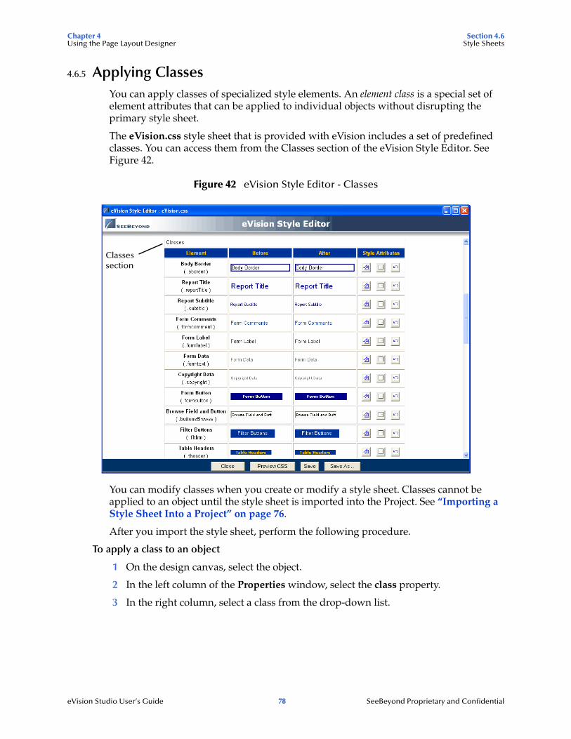
Chapter 4 Section 4.6Using the Page Layout Designer Style Sheets
eVision Studio User’s Guide 78 SeeBeyond Proprietary and Confidential
4.6.5 Applying ClassesYou can apply classes of specialized style elements. An element class is a special set of element attributes that can be applied to individual objects without disrupting the primary style sheet.
The eVision.css style sheet that is provided with eVision includes a set of predefined classes. You can access them from the Classes section of the eVision Style Editor. See Figure 42.
Figure 42 eVision Style Editor - Classes
You can modify classes when you create or modify a style sheet. Classes cannot be applied to an object until the style sheet is imported into the Project. See “Importing a Style Sheet Into a Project” on page 76.
After you import the style sheet, perform the following procedure.
To apply a class to an object
1 On the design canvas, select the object.
2 In the left column of the Properties window, select the class property.
3 In the right column, select a class from the drop-down list.
Classes section
Chapter 4 Section 4.7Using the Page Layout Designer Additional Features
eVision Studio User’s Guide 79 SeeBeyond Proprietary and Confidential
4.6.6 Referencing an External FileAccording to the CSS specification, a style sheet can include a reference to an external file. For example, the following property/value pair sets the background of an element to an image.
background-image: url("glblnav_selected.gif");
If you want to use a custom style sheet that includes references to one or more external file, then perform the following steps.
To incorporate a reference to an external file
1 Package the external file(s) in a .zip file. If the url reference points to a subdirectory, be sure that the files in the .zip file use the same directory structure.
2 Import the .zip file into the Project. You can follow the procedure in “Importing Images” on page 41.
3 For each Page Layout where the style sheet is used, set the imports property to the imported .zip file. To access the imports property, select the page property type from the Properties drop-down menu.
4.7 Additional FeaturesThis section describes a variety of additional Page Layout Designer features.
4.7.1 Setting the Title of a Page LayoutThe title property of a Page Layout enables you to specify the text that appears in the title bar at run time.
If you do not assign a value for the title property, then the servlet context appears in the title bar. For information about the servlet context, see “Servlet Context” on page 137.
You can also set the title dynamically. In the Page Flow Designer, the title property is exposed as a node of the Business Process Attributes.
To set the title of a Page Layout
1 From the Properties drop-down arrow, select the page property type.
2 In the left column, select the title property.
3 In the right column, enter the value that you want to appear in the title bar.
Chapter 4 Section 4.7Using the Page Layout Designer Additional Features
eVision Studio User’s Guide 80 SeeBeyond Proprietary and Confidential
4.7.2 Setting a Background Image or Color for a Page LayoutYou can specify that the background of a Page Layout will contain an image or a color. The image or color appears in Preview mode, but not on the design canvas.
Important: Before you set a background image, you must import the image into the Project. For more information, see “Importing Images” on page 41.
To set a background image for a Page Layout
1 From the Properties drop-down arrow, select the page property type.
2 In the left column, select the background property.
3 In the right column, click the Command button (...). The Enter value for “background” dialog box appears.
4 Select the image and click Open.
5 If you want to remove the background image at a later time, right-click the design canvas and select Clear Background Image.
To set a background color for a Page Layout
1 From the Properties drop-down arrow, select the page property type.
2 In the left column, select the bgcolor property.
3 In the right column, click the Command button (...). The Pick a Color dialog box appears.
4 Select a color. If you want to have more control over the settings, click the Advanced button.
5 Click OK.
4.7.3 Automatically Refreshing Page LayoutsYou can indicate that a Page Layout will automatically refresh after a specified period of time. A typical use for this feature is when the page contains dynamic content.
The following procedure requires you to set the refresh and refreshSecs properties of the Page Layout. If the Page Layout is not going to be the first Page Layout in a Page Flow, then you must set the method property of the immediately preceding Page Layout.
To automatically refresh a Page Layout
1 Open the Page Layout that you want to be automatically refreshed.
2 In the Properties window, select the page property type from the drop-down menu.
3 In the left column, select the refresh property.
4 In the right column, set the value to true.
A new property called refreshSecs appears. See Figure 43.
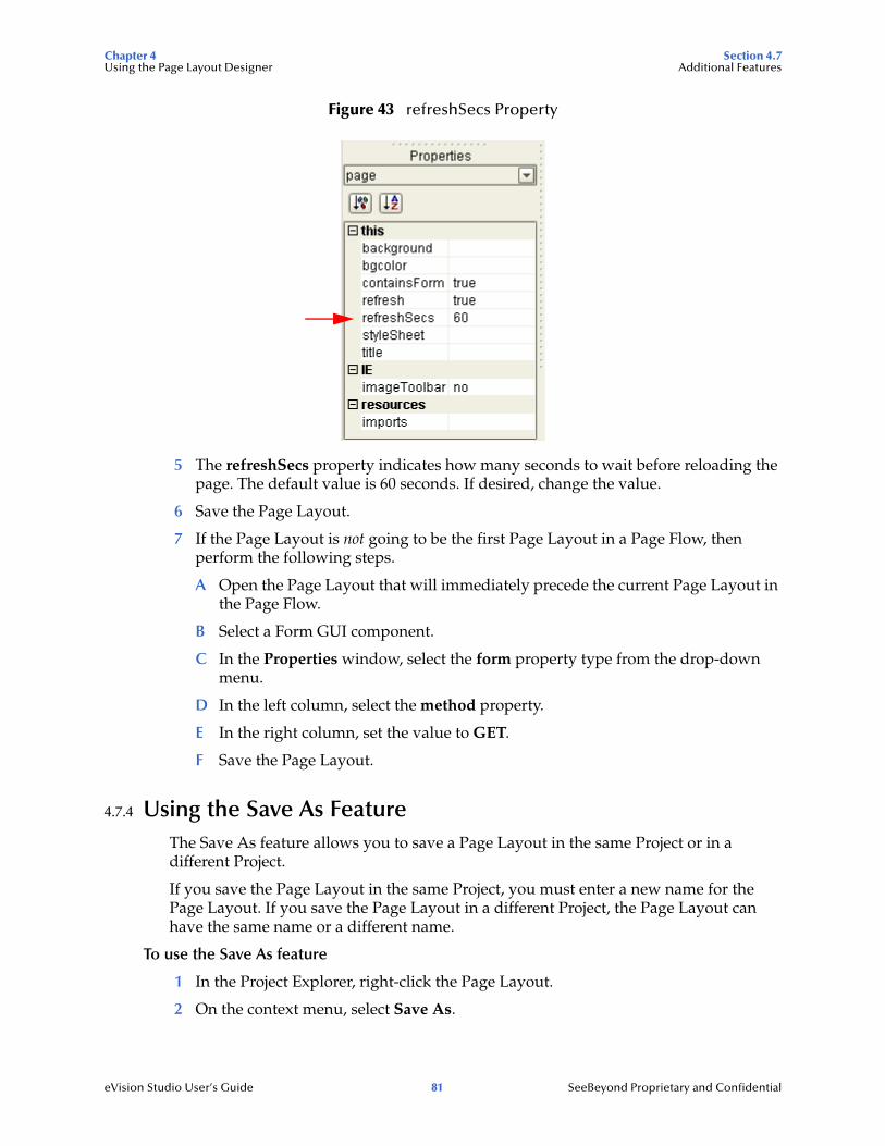
Chapter 4 Section 4.7Using the Page Layout Designer Additional Features
eVision Studio User’s Guide 81 SeeBeyond Proprietary and Confidential
Figure 43 refreshSecs Property
5 The refreshSecs property indicates how many seconds to wait before reloading the page. The default value is 60 seconds. If desired, change the value.
6 Save the Page Layout.
7 If the Page Layout is not going to be the first Page Layout in a Page Flow, then perform the following steps.
A Open the Page Layout that will immediately precede the current Page Layout in the Page Flow.
B Select a Form GUI component.
C In the Properties window, select the form property type from the drop-down menu.
D In the left column, select the method property.
E In the right column, set the value to GET.
F Save the Page Layout.
4.7.4 Using the Save As FeatureThe Save As feature allows you to save a Page Layout in the same Project or in a different Project.
If you save the Page Layout in the same Project, you must enter a new name for the Page Layout. If you save the Page Layout in a different Project, the Page Layout can have the same name or a different name.
To use the Save As feature
1 In the Project Explorer, right-click the Page Layout.
2 On the context menu, select Save As.

Chapter 4 Section 4.8Using the Page Layout Designer Page Links
eVision Studio User’s Guide 82 SeeBeyond Proprietary and Confidential
The Save as dialog box appears. See Figure 44.
Figure 44 Save as Dialog Box
3 If you want to save the Page Layout in a different Project, navigate to the desired Project.
4 If you want to change the Page Layout name, do so in the Name field.
5 Click Save.
4.8 Page LinksPage Links enable you to create links to other Page Layouts. A special type of Page Link points to the home page of an eVision Web application. You use the Page Link Wizard to create Page Links.
In the Page Layout Designer, you can drag a Page Link from the Project Explorer and drop it onto a Page Layout.
In the Page Flow Designer, you can drag the link operation of a Page Link from the Project Explorer and drop it onto a Page Flow.
“Event Based Decision” on page 114 describes the use of Page Links with the Event Based Decision element. The sample eVision Web application in Chapter 7, “Page Flow Designer Tutorial” includes a Page Link that points to the home page.
Note: Do not confuse Page Links with the Link component. For information about the Link component, see “Links” on page 44.
To create a Page Link
1 In the Project Explorer, right-click the Project.
2 On the context menu, click New, and then select Page Link.
Step 1 of the Page Link Wizard appears. See Figure 45.

Chapter 4 Section 4.8Using the Page Layout Designer Page Links
eVision Studio User’s Guide 83 SeeBeyond Proprietary and Confidential
Figure 45 Page Link Wizard - Step 1
3 In the Page Link Name field, type a descriptive name for the link.
4 If you want the link to point to the Page Flow’s home page, check Designate as Home Page.
The page will be the first page that appears when a user accesses the Web application. In a Page Flow, you can designate only one page as the home page.
5 Click Next.
Step 2 of the Page Link Wizard appears. See Figure 46.
Figure 46 Page Link Wizard - Step 2
6 If desired, add a Page Link parameter.

Chapter 4 Section 4.8Using the Page Layout Designer Page Links
eVision Studio User’s Guide 84 SeeBeyond Proprietary and Confidential
A Page Link parameter is a data type that is passed via the link to a GUI component on the linked destination page. You can pass one or more parameters.
Assume that you create a Project that includes the Page Flow shown in “Event Based Decision” on page 114. If the plCredit Page Link contains a parameter, then the parameter is passed to the pgCredit Page Layout when a user clicks the link.
In the Name column, enter the parameter’s name (the internal system name used when specifying a target for the link). In the Value column, enter the data to be passed via the link to a target object on the destination page.
Note: You must assign a value to the Page Link, even if the value is dynamically assigned at run time.
To add another parameter, click Add and enter the name and value. To delete a parameter, select the parameter and click Delete. To move a parameter up one level in the stack, select the parameter and click Up. To move a parameter down one level in the stack, select the parameter and click Down.
7 Click Finish.
The Page Link is added to your Project in the Project Explorer. See Figure 47.
Figure 47 Page Link in the Project Explorer
Page Link

eVision Studio User’s Guide 85 SeeBeyond Proprietary and Confidential
Chapter 5
Page Layout Designer Tutorial
This chapter guides you through the process of starting a new page, placing GUI components on the canvas, and using the property sheets.
What’s in This Chapter
“Tutorial Overview” on page 85
“Downloading the Sample Files” on page 86
“Starting a New Page Layout” on page 87
“Importing the Image Files” on page 90
“Placing GUI Components on the Canvas” on page 91
“Aligning Objects Using the Alignment Tools” on page 99
“Previewing the Finished Web Page” on page 100
“Using the Version Control System” on page 101
5.1 Tutorial OverviewIn the following tutorial, you build an input page for a small payroll calculation system. The purpose of the exercise is to create a finished Web page that you can preview in your browser. In the process of constructing the page, you will become familiar with the Page Layout Designer. For an example of the finished page, see Figure 48.

Chapter 5 Section 5.2Page Layout Designer Tutorial Downloading the Sample Files
eVision Studio User’s Guide 86 SeeBeyond Proprietary and Confidential
Figure 48 Finished Web Page
5.2 Downloading the Sample FilesThe sample files are provided in .zip file format. They are included in the eVision Studio documentation .sar file. The first step in this tutorial is to download the sample files from the Repository.
The Repository must be running before you can use Enterprise Manager or Enterprise Designer. The first step of any procedure is to make sure that the Repository is running. The SeeBeyond ICAN Suite Installation Guide describes how to start the Repository.
To download the sample files
1 Start Internet Explorer.
2 In the Address field, enter http://hostname:portnumber
where
hostname is the TCP/IP host name of the server where the Repository is installed.
portnumber is the base port number of the Repository.
The SeeBeyond Customer Login window of Enterprise Manager appears.
3 Enter your username and password.
4 Click Login.
The Enterprise Manager home page appears.
5 Click the DOCUMENTATION tab.
6 In the left frame of the Documentation page, click eVision Studio.
Note: If you do not see an eVision Studio link in the left frame, then the eVision Studio Documentation .sar file must be uploaded. See Chapter 3, “Installing eVision Studio” on page 26.

Chapter 5 Section 5.3Page Layout Designer Tutorial Starting a New Page Layout
eVision Studio User’s Guide 87 SeeBeyond Proprietary and Confidential
7 In the right frame of the Documentation page, click Download Sample.
8 Using an archive utility (such as WinZip), extract the sample files to a folder on your computer. Remember where you saved the files. If you use the folder names stored in the archive, the sample files will be stored in a directory called eVision_Sample.
The sample files are:
blueBG.gif
i_seebeyondlogo.gif
eVisionSampleComponents.zip
eVisionTutorial_sample.zip
In this tutorial, you use the blueBG.gif and i_seebeyondlogo.gif files.
5.3 Starting a New Page LayoutYou use the Page Layout Wizard to add a Page Layout to a Project.
To start a new Page Layout
1 Start Enterprise Designer.
2 In the Project Explorer, right-click the Repository.
3 On the context menu, select New Project.
A Project icon is added to the Enterprise Explorer tree. The new branch is called Projectn, where n is the next sequential default Project number. The keyboard focus is inside the Projectn field. See Figure 49.
Figure 49 New Project in Project Explorer
4 Without moving the cursor, type a name for the new Project (for example, MyProject).
5 Press Enter.
6 Right-click the Project.
7 On the context menu, click New, and then select Page Layout.

Chapter 5 Section 5.3Page Layout Designer Tutorial Starting a New Page Layout
eVision Studio User’s Guide 88 SeeBeyond Proprietary and Confidential
Step 1 of the Page Layout Wizard appears. See Figure 50.
Figure 50 Page Layout Wizard - Step 1
8 In the Page Layout Name field, type a name for the Page Layout (for example, MyWebPage).
9 Click Next.
Step 2 of the Page Layout Wizard appears. See Figure 51.
Figure 51 Page Layout Wizard - Step 2
10 The wizard allows you to select any of the preconfigured Web pages based on a particular Project’s requirements. For this Project, you start with a blank page. Therefore, click the Blank Page icon.

Chapter 5 Section 5.3Page Layout Designer Tutorial Starting a New Page Layout
eVision Studio User’s Guide 89 SeeBeyond Proprietary and Confidential
11 Click Finish.
A new Page Layout is added to the Project Explorer. See Figure 52.
Figure 52 New Page Layout in Project Explorer
The Page Layout Designer appears in the work area of Enterprise Designer with a blank canvas. See Figure 53.
Figure 53 Page Layout Designer with a Blank Canvas
You have just created a blank Web page and started the Page Layout Designer. You will now use the Page Layout Designer tools and pre-built GUI components to create a Web page that receives user input.

Chapter 5 Section 5.4Page Layout Designer Tutorial Importing the Image Files
eVision Studio User’s Guide 90 SeeBeyond Proprietary and Confidential
5.4 Importing the Image FilesThe sample Web page requires that you import two image files for use in the Page Layout: a background image (blueBG.gif) and a SeeBeyond logo (i_seebeyondlogo.gif). Before graphic images can be used in an eVision Web page, you must import them into the Project.
To import the image files
1 In the Project Explorer, right-click the Project.
2 On the context menu, click New, and then select File.
The Import Files dialog box appears. See Figure 54.
3 Navigate to the folder containing the image files that you extracted in “Downloading the Sample Files” on page 86.
Graphic images can reside in any directory that is accessible to your computer, locally or on a network.
4 Select blueBG.gif and click Select. The file name appears in the Selected Import Files box.
5 Select i_seebeyondlogo.gif and click Select. The file name appears in the Selected Import Files box.
Figure 54 Import Files Dialog Box
6 Click Import.

Chapter 5 Section 5.5Page Layout Designer Tutorial Placing GUI Components on the Canvas
eVision Studio User’s Guide 91 SeeBeyond Proprietary and Confidential
The image files are now part of your Project. See Figure 55.
Figure 55 Imported Image Files in Project Explorer
5.5 Placing GUI Components on the CanvasIn this section, you place a variety of GUI components on the Page Layout Designer canvas. You also specify some of the components’ properties.
Before you begin, make sure that the HTML Objects palette is in front. See Figure 56.
Figure 56 HTML Objects Palette
5.5.1 Create the Background Layer ComponentThe blueBG.gif file will be used as the background of the Web page.
1 From the HTML Objects palette, drag the Image icon onto the approximate center of the canvas.
The Enter value dialog box appears. See Figure 57.

Chapter 5 Section 5.5Page Layout Designer Tutorial Placing GUI Components on the Canvas
eVision Studio User’s Guide 92 SeeBeyond Proprietary and Confidential
Figure 57 Enter value Dialog Box
2 Select the blueBG.gif file and click Open.
The Image component appears with a gold outline. The Properties sheet for the Image component is automatically displayed. See Figure 58.
Figure 58 Properties Sheet for the Image Component
3 In the Properties sheet, define the value for lname by doing the following:
A In the left column, select the lname property.

Chapter 5 Section 5.5Page Layout Designer Tutorial Placing GUI Components on the Canvas
eVision Studio User’s Guide 93 SeeBeyond Proprietary and Confidential
B In the right column, delete the default value and enter Background.
lname is the internal, logical system name for the component, used to identify the component in a Page Flow.
4 In the Properties sheet, define the value for z-index by doing the following:
A In the left column, select the z-index property.
B In the right column, delete the default value and enter -1.
z-index specifies the placement of the object in the stack order. Setting the z-index property to -1 enables you to place components on top of the background layer and have the components be immediately visible. For more information, see “Moving Overlapping Components in the Z-Direction” on page 72.
5 If you want to move the component, click the component inside the boundary and drag it to the new location.
5.5.2 Create the Page Banner ComponentThe i_seebeyondlogo.gif file will be used as the company logo.
1 From the HTML Objects palette, drag the Image icon onto the canvas and inside the boundaries of the background image.
The Enter value dialog box appears.
2 Select the i_seebeyondlogo.gif file and click Open.
The Properties sheet for the Image component is automatically displayed.
3 In the Properties sheet, define the value for lname by doing the following:
A In the left column, select the lname property.
B In the right column, delete the default value and enter logo.
4 If you want to move the component, click the component inside the boundary and drag it to the new location. Figure 48 on page 86 shows the recommended location.
5.5.3 Create the Employee Name Label ComponentThis component identifies the input field where the user enters his or her name.
1 From the HTML Objects palette, drag the Label icon onto the canvas.
2 Place the component left-aligned with the logo component.
The Properties sheet for the Label component is automatically displayed.
3 In the Properties sheet, define the value for lname by doing the following:
A In the left column, select the lname property.
B In the right column, delete the default value and enter EmpName.
4 In the Properties sheet, define the value for text by doing the following:
A In the left column, select the text property.

Chapter 5 Section 5.5Page Layout Designer Tutorial Placing GUI Components on the Canvas
eVision Studio User’s Guide 94 SeeBeyond Proprietary and Confidential
B In the right column, click the [default text] field. The Enter value for “text” window appears.
C Delete the [default text] string and type Employee Name.
D Click OK.
5 On the canvas, the text string may appear truncated. To see the entire text string:
A Select the component.
B Press and hold the Shift key.
C Press the right arrow key until the entire text string is visible.
5.5.4 Create the Hours Worked Label ComponentThis component identifies the input field where the user enters the number of hours worked.
1 From the HTML Objects palette, drag the Label icon onto the canvas.
2 Place the component under and left-aligned with the EmpName component.
The Properties sheet for the Label component is automatically displayed.
3 In the Properties sheet, define the value for lname by doing the following:
A In the left column, click the lname property.
B In the right column, delete the default value and enter HoursWorked.
4 In the Properties sheet, define the value for text by doing the following:
A In the left column, select the text property.
B In the right column, click the [default text] field. The Enter value for “text” window appears.
C Delete the [default text] string and type Hours Worked.
D Click OK.
5 On the canvas, the text string may appear truncated. To see the entire text string:
A Select the component.
B Press and hold the Shift key.
C Press the right arrow key until the entire text string is visible.
5.5.5 Create the Rate Label ComponentThis component identifies the drop-down list where the user selects his or her hourly pay rate.
1 From the HTML Objects palette, drag the Label icon onto the canvas.
2 Place the component under and left-aligned with the HoursWorked component.
The Properties sheet for the Label component is automatically displayed.

Chapter 5 Section 5.5Page Layout Designer Tutorial Placing GUI Components on the Canvas
eVision Studio User’s Guide 95 SeeBeyond Proprietary and Confidential
3 In the Properties sheet, define the value for lname by doing the following:
A In the left column, click the lname property.
B In the right column, delete the default value and enter Rate.
4 In the Properties sheet, define the value for text by doing the following:
A In the left column, select the text property.
B In the right column, click the [default text] field. The Enter value for “text” window appears.
C Delete the [default text] string and type Rate.
D Click OK.
5 On the File menu, click Save All.
Check your progress. The page should look like the example in Figure 59.
Figure 59 Progress Check 1
5.5.6 Display the Form Objects PaletteTo bring the Form Objects palette to the front, click the Form Objects title bar. See Figure 60.

Chapter 5 Section 5.5Page Layout Designer Tutorial Placing GUI Components on the Canvas
eVision Studio User’s Guide 96 SeeBeyond Proprietary and Confidential
Figure 60 Form Objects Palette
5.5.7 Create the Employee Name Input Field ComponentThis component will be displayed to users as an empty input field to the right of the Employee Name label.
1 From the Form Objects palette, drag the Text Box icon onto the canvas.
2 Align the component horizontally with and to the right of the EmpName component. Make sure that the components do not overlap.
The Properties sheet for the Text Box component is automatically displayed.
3 In the Properties sheet, define the value for lname by doing the following:
A In the left column, click the lname property.
B In the right column, delete the default value and enter EmpNameInput.
4 In the Properties sheet, define the value for value by doing the following:
A In the left column, select the value property.
B In the right column, delete the [default text] string. (You want this input field to be initially blank, to receive input from users.)
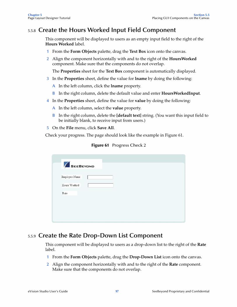
Chapter 5 Section 5.5Page Layout Designer Tutorial Placing GUI Components on the Canvas
eVision Studio User’s Guide 97 SeeBeyond Proprietary and Confidential
5.5.8 Create the Hours Worked Input Field ComponentThis component will be displayed to users as an empty input field to the right of the Hours Worked label.
1 From the Form Objects palette, drag the Text Box icon onto the canvas.
2 Align the component horizontally with and to the right of the HoursWorked component. Make sure that the components do not overlap.
The Properties sheet for the Text Box component is automatically displayed.
3 In the Properties sheet, define the value for lname by doing the following:
A In the left column, click the lname property.
B In the right column, delete the default value and enter HoursWorkedInput.
4 In the Properties sheet, define the value for value by doing the following:
A In the left column, select the value property.
B In the right column, delete the [default text] string. (You want this input field to be initially blank, to receive input from users.)
5 On the File menu, click Save All.
Check your progress. The page should look like the example in Figure 61.
Figure 61 Progress Check 2
5.5.9 Create the Rate Drop-Down List ComponentThis component will be displayed to users as a drop-down list to the right of the Rate label.
1 From the Form Objects palette, drag the Drop-Down List icon onto the canvas.
2 Align the component horizontally with and to the right of the Rate component. Make sure that the components do not overlap.

Chapter 5 Section 5.5Page Layout Designer Tutorial Placing GUI Components on the Canvas
eVision Studio User’s Guide 98 SeeBeyond Proprietary and Confidential
The Properties sheet for the Drop-Down List component is automatically displayed.
3 In the Properties sheet, define the value for lname by doing the following:
A In the left column, click the lname property.
B In the right column, delete the default value and enter RateDropDown.
4 On the canvas, right-click the Drop-Down List component.
5 On the context menu, select Edit Options.
The Edit Options dialog box appears.
6 Under the Labels heading, click the empty input field and type 20. This is the default pay rate that will be displayed to users in the drop-down list on the Web page.
7 Under the Values heading, click the empty input field and type 20. This is the label for the drop-down list entry.
8 To add three additional input rows:
A Click Add three times.
B In row 2, type 25 under the Labels heading and again under the Values heading.
C In row 3, type 30 under the Labels heading and again under the Values heading.
D In row 4, type 40 under the Labels heading and again under the Values heading.
The Edit Options dialog box should now look like Figure 62.
Figure 62 Edit Options Dialog Box

Chapter 5 Section 5.6Page Layout Designer Tutorial Aligning Objects Using the Alignment Tools
eVision Studio User’s Guide 99 SeeBeyond Proprietary and Confidential
9 Click OK.
5.5.10 Create the Submit Button ComponentThis component will be displayed to users as a button with the label Submit.
1 From the Form Objects palette, drag the Submit Button icon onto the canvas.
2 Place the component below and right-aligned with the Drop-Down List component.
The Properties sheet for the Submit Button component is automatically displayed.
3 In the Properties sheet, define the value for lname by doing the following:
A In the left column, click the lname field.
B In the right column, delete the default value and enter Submit.
4 On the File menu, click Save All.
Check your progress. The page should look like the example in Figure 63.
Figure 63 Progress Check 3
5.6 Aligning Objects Using the Alignment ToolsIf the GUI components are not precisely aligned, or if the space between the objects is inconsistent, you can adjust the alignment of the components using the alignment tools.
To choose two or more objects to be aligned, do the following:
1 Press and hold the Shift key on your computer.
2 Select the objects that you want to align.
3 Click the desired alignment tool on the Page Layout Designer toolbar. Table 9 describes the alignment tools.

Chapter 5 Section 5.7Page Layout Designer Tutorial Previewing the Finished Web Page
eVision Studio User’s Guide 100 SeeBeyond Proprietary and Confidential
Table 9 Alignment Tools
5.7 Previewing the Finished Web PageTo preview the finished Web page in your browser, click the Preview icon on the Page Layout Designer toolbar.
Figure 64 Page Layout Designer Toolbar
The page should look like the example in Figure 65.
Tool Name Purpose
Left Align Aligns two or more selected components with the left-most component in the selected group.
Right Align Aligns two or more selected components with the right-most component in the selected group.
Center Align Aligns two or more selected components with the center of the canvas (the center of the Web page).
Top Align Aligns two or more selected components with the top-most component in the selected group.
Bottom Align Aligns two or more selected components with the bottom component in the selected group.
Vertical Spacing Creates equal vertical spacing between object in a group based on an averaging algorithm.
Horizontal Spacing Creates equal horizontal spacing between objects in a group based on an averaging algorithm.
Preview

Chapter 5 Section 5.8Page Layout Designer Tutorial Using the Version Control System
eVision Studio User’s Guide 101 SeeBeyond Proprietary and Confidential
Figure 65 Finished Web Page in Preview Mode
You can enter text in the text boxes and select values from the drop-down list. However, the submit button does not work.
5.8 Using the Version Control SystemThe ICAN Suite includes a Version Control system that allows you to maintain multiple versions of selected Project or Environment components. The version history of each component is recorded to a log file, and can be viewed by means of a menu option. For more information, see the eGate Integrator User’s Guide.
You can practice using the Version Control system with the Page Layout that you created in this chapter.
To check in a Page Layout
1 In the Project Explorer, right-click the Page Layout.
2 On the context menu, select Check In.
The Version Control - Check In dialog box appears. See Figure 66.
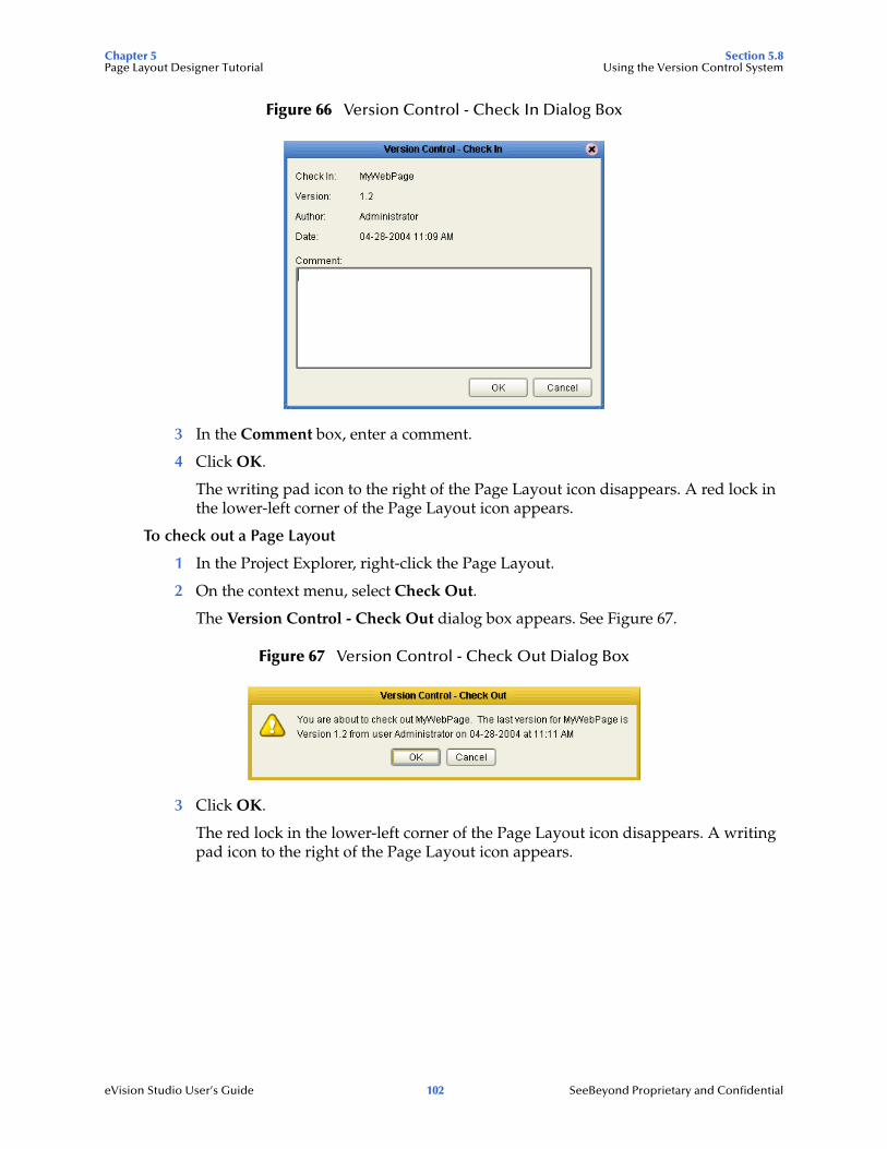
Chapter 5 Section 5.8Page Layout Designer Tutorial Using the Version Control System
eVision Studio User’s Guide 102 SeeBeyond Proprietary and Confidential
Figure 66 Version Control - Check In Dialog Box
3 In the Comment box, enter a comment.
4 Click OK.
The writing pad icon to the right of the Page Layout icon disappears. A red lock in the lower-left corner of the Page Layout icon appears.
To check out a Page Layout
1 In the Project Explorer, right-click the Page Layout.
2 On the context menu, select Check Out.
The Version Control - Check Out dialog box appears. See Figure 67.
Figure 67 Version Control - Check Out Dialog Box
3 Click OK.
The red lock in the lower-left corner of the Page Layout icon disappears. A writing pad icon to the right of the Page Layout icon appears.

eVision Studio User’s Guide 103 SeeBeyond Proprietary and Confidential
Chapter 6
Using the Page Flow Designer
This chapter describes how to use the Page Flow Designer to create an eVision Studio Web application, which consists of Page Layouts and specialized design elements that are linked together.
What’s in This Chapter
“Page Flow Designer Overview” on page 103
“Page Flow Designer Tools” on page 105
“Page Flow Elements” on page 106
“Configuring Page Flow Designer Elements” on page 112
“Page Flow Properties” on page 124
“Persisting Page Flows” on page 132
“Page Flows in Connectivity Maps” on page 133
“Deploying Page Flows” on page 136
“Invoking Another Page Flow or a Business Process” on page 141
6.1 Page Flow Designer OverviewA Page Flow is a structured series of Web pages that comprise a Web-enabled business process.
A Web-enabled business process can be an internal service, or it can be exposed as an external application over the Web. A Page Flow can involve a variety of participants, and may include internal and external computer systems. When you create a Page Flow, you are creating a graphical representation of what will become a fully functional and deployable Web application.
6.1.1. Adding a Page Flow to a ProjectWhen you add a Page Flow to a Project, the Page Flow Designer opens an empty Page Flow canvas that enables you to place Web pages and other design elements and then connect them together in a sequence. Before you can start building a Page Flow, you must add the Page Flow to your Project.

Chapter 6 Section 6.1Using the Page Flow Designer Page Flow Designer Overview
eVision Studio User’s Guide 104 SeeBeyond Proprietary and Confidential
To add a Page Flow to a Project
1 In the Project Explorer, right-click the Project.
2 On the context menu, click New, and then select Page Flow.
3 If desired, change the default name of the Page Flow.
6.1.2. Adding Components to a Page FlowAfter you add a Page Flow to a Project, you drag and drop Page Flow elements and Web page operations onto the canvas. An example of a Web page operation is the show operation of a Page Layout. You then link the components together.
The Page Flow Designer provides the tools to lay out and connect Page Flow elements and other specialized elements. Figure 68 shows an example of the Page Flow Designer GUI.
Figure 68 Page Flow in the Page Flow Designer
When you start a new Web application project, the Start and End icons automatically appear on the blank Page Flow Designer canvas. There can be only one starting point for a Page Flow. There can be multiple end points.
To add components to a Page Flow
1 Drag the desired Page Flow elements and Web page operations onto the Page Flow Designer canvas.
2 Create links between the elements.
3 Save the Page Flow to the Repository.
This action validates the connectivity of the Page Flow, generates the code to run it, and saves the Page Flow in the Repository.
canvasProject Explorer
elements
show operation

Chapter 6 Section 6.2Using the Page Flow Designer Page Flow Designer Tools
eVision Studio User’s Guide 105 SeeBeyond Proprietary and Confidential
6.2 Page Flow Designer ToolsThe Page Flow Designer tools are shown in Figure 69.
Figure 69 Page Flow Designer Tools
The Page Flow Designer tools are described in Table 10.
Table 10 Page Flow Designer Tools
Tool Name Description
Display Business Rule Designer
Opens a window in the lower portion of the Page Flow Designer that enables you to configure relationships between Input and Output attributes.
Show Page Flow Code Opens a window in the lower portion of the Page Flow Designer and displays the BPEL4WS code generated by the Page Flow Designer.
Synchronize Graphical Model and Page Flow Code
Synchronizes the Page Flow on the canvas with the underlying code generation.
Validate Page Flow Model Checks for and reports on execution errors in the Page Flow code.
Show Property Sheet Allows you to set alert, logging, message event, and timer event properties for the Page Flow.
Print Prints the Page Flow screen image. Allows you to control the scale of the printed image.
Zoom Increases or decreases the Page Flow image on the screen.
Synchronize Graphical Model and Page Flow Code
Display Business Rule Designer
Show Property Sheet
PrintValidate Page Flow Model
Show Page Flow Code
Zoom

Chapter 6 Section 6.3Using the Page Flow Designer Page Flow Elements
eVision Studio User’s Guide 106 SeeBeyond Proprietary and Confidential
6.3 Page Flow ElementsThe Page Flow Designer provides elements that allow you to customize and extend a Page Flow. You drag pages from the Project Explorer and and drop them onto the design canvas. In addition to Web pages, Page Flows can contain basic elements, branching elements, and intermediate events.
Chapter 7, “Page Flow Designer Tutorial” illustrates how to use many of these elements.
6.3.1. Basic ElementsYou can add several types of basic elements to a Page Flow. In addition, the Start Node and End Node elements are automatically added to a Page Flow. See Table 11.
Table 11 Basic Elements
Icon Name Description
Start Node The Start Node element indicates the start of the Page Flow. The Start Node is automatically added when you create a Page Flow. A Start Node can connect to a Page Link or an Event Based Decision element.
Link Links define the connectivity of the Page Flow by connecting page and sub-process elements together.
When you select a link, a context menu allows you to configure how data is going to be passed to and from the underlying component or Web Service using Attributes. The Page Flow Designer ensures that the Page Flow is correctly linked by rejecting invalid links.
Links can also accept mapped values. A link with mapped values will displayed with the “map” icon.
End Node The End Node element indicates the completed state of a Page Flow. The End Node is automatically added when you create a Page Flow.
Receive The Receive element can connect to a Page Link or can connect to a Start Node via a Page Link. It is used to indicate the invocation of the Page Flow. The Receive element represents the actual method by which a Page Flow is initiated, for example: A user types a URL into the browser and a servlet initiates the Page Flow.
Activity An Activity is a step in the Page Flow in which the Page Flow Engine will invoke a Web service or an eGate component. Depending on the configuration of the component, a response may or may not be required. One example would be a synchronous extraction process from a database to return the credit status of a trading partner.

Chapter 6 Section 6.3Using the Page Flow Designer Page Flow Elements
eVision Studio User’s Guide 107 SeeBeyond Proprietary and Confidential
Reply The Reply element allows a Page Flow to respond to the external system or user that originally invoked the Page Flow. The original Receive at the beginning of the Page Flow is paired with the Reply at the end. When a message must be sent back to the caller of the Page Flow, the Reply uses information that correlates the message in the calling system.
A Reply is the last step in a Page Flow that acts as a Web service or sub-process. A Reply correlates the outbound message back to the calling process. For example, it can reply to an external system as a Web service.
Business Rule The Business Rule element sets data values, including task assignments. It is used when pages have multiple data mappings between the invocation of human tasks or automated systems.
Compensate The Compensate element is used to invoke compensation on an inner scope that has already completed normally. This construct can be invoked only from within a fault handler or another compensation handler.
For more information, see the “Exception Handling” chapter in the eInsight Business Process Manager User’s Guide.
Empty The Empty element allows data to pass through without changes.
Wait The Wait element suspends processing for a specified period of time or until a deadline is reached.
If a Page Flow contains two simultaneous paths within a set framework (one for the Page Flow, one for the timer) and the timer condition takes place first, then an exception is thrown and handled, and the Page Flow ends.
Icon Name Description

Chapter 6 Section 6.3Using the Page Flow Designer Page Flow Elements
eVision Studio User’s Guide 108 SeeBeyond Proprietary and Confidential
6.3.2. Branching ElementsBranching elements allow you to specify the logical flow of information. eVision provides three types of branching elements: Decision, Event Based Decision, and Flow. See Table 12.
To add a Branching element to the Page Flow Designer canvas
1 On the Page Flow Designer toolbar, click the expansion arrow on the Branching Activities icon.
2 Click the Branching element that you want to use and drag it to the Page Flow Designer canvas.
Table 12 Branching Elements
Icon Name Description
Decision The Decision element allows one of several possible paths to execute, based on expression logic. This element is used to create complex expressions that determine the path of the Page Flow. It also contains the expression and connection names.
The Decision element allows you to define expressions that are evaluated to determine the routing of the Page Flow. Expressions are built using the mapping interface and Page Flow attributes.
Note: The Decision element is structured to automatically raise a run-time Exception to alert you to Page Flow errors during construction. You can set this value to Return True or Return False. However, it is not recommended during the construction phase; errors can be hidden during development and only surface in the post-deployment, run-time environment.
Event Based Decision
The Event Based Decision element allows one of several possible paths to execute, based on which link the user has selected.
For more information, see “Event Based Decision” on page 114.
Flow The Flow element specifies that one or more pages and/or processes are to flow concurrently.

Chapter 6 Section 6.3Using the Page Flow Designer Page Flow Elements
eVision Studio User’s Guide 109 SeeBeyond Proprietary and Confidential
6.3.3. Intermediate EventsIntermediate events are elements that can interrupt a Page Flow. Some intermediate events handle exceptions that may occur at run time or compensate for exceptions. See Table 13.
Table 13 Intermediate Events
Icon Name Description
Compensation Handler
The Compensation Handler is used when something in a Page Flow fails and requires a rollback based on upstream activities. On an automatic basis in the Page Flow, upstream steps in the Page Flow are notified that the failure has occurred and certain transactions need to be reversed, sometimes in a sequential order. The Compensation Handler allows you to design the process and circumstances in which the compensation takes place.
Catch Named Exception
Each automated system (backend system) or Web service can publish its possible error codes (for instance, fault 15 is “bad data”). Those codes can be mapped to exception handlers. Each exception handler is connected to the scope that surrounds one or more steps in a Page Flow. The components within that scope will throw the exceptions when errors occur and the exception handler will automatically initiate the appropriate process to handle the problem.
For more information, see the “Exception Handling” chapter in the eInsight Business Process Manager User’s Guide.
Catch All Exceptions
The Catch All Exceptions handler is configured to handle all exceptions.
For more information, see the “Exception Handling” chapter in the eInsight Business Process Manager User’s Guide.
Message Event The Message Event is similar to a Receive Activity, but it occurs only in the middle of a process.
For more information, see “Event Based Decision” on page 114.
Timer Event The Timer Event imposes a time-out condition on pages, groups of pages, or a Page Flow as a whole to ensure that processes complete within a specified time-frame. Conditions also allow the creation of the process that takes place after a time-out condition takes place.
For more information, see “Event Based Decision” on page 114.
Throw The Throw handler throws exceptions.
Terminate Process
The Terminate Process handler ends the Page Flow.
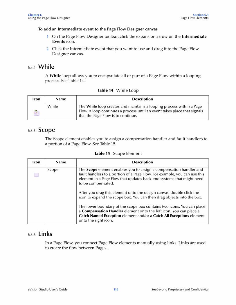
Chapter 6 Section 6.3Using the Page Flow Designer Page Flow Elements
eVision Studio User’s Guide 110 SeeBeyond Proprietary and Confidential
To add an Intermediate event to the Page Flow Designer canvas
1 On the Page Flow Designer toolbar, click the expansion arrow on the Intermediate Events icon.
2 Click the Intermediate event that you want to use and drag it to the Page Flow Designer canvas.
6.3.4. WhileA While loop allows you to encapsulate all or part of a Page Flow within a looping process. See Table 14.
6.3.5. ScopeThe Scope element enables you to assign a compensation handler and fault handlers to a portion of a Page Flow. See Table 15.
6.3.6. LinksIn a Page Flow, you connect Page Flow elements manually using links. Links are used to create the flow between Pages.
Table 14 While Loop
Icon Name Description
While The While loop creates and maintains a looping process within a Page Flow. A loop continues a process until an event takes place that signals that the Page Flow is to continue.
Table 15 Scope Element
Icon Name Description
Scope The Scope element enables you to assign a compensation handler and fault handlers to a portion of a Page Flow. For example, you can use this element in a Page Flow that updates back-end systems that might need to be compensated.
After you drag this element onto the design canvas, double click the icon to expand the scope box. You can then drag objects into the box.
The lower boundary of the scope box contains two icons. You can place a Compensation Handler element onto the left icon. You can place a Catch Named Exception element and/or a Catch All Exceptions element onto the right icon.

Chapter 6 Section 6.3Using the Page Flow Designer Page Flow Elements
eVision Studio User’s Guide 111 SeeBeyond Proprietary and Confidential
To link Web pages and other Page Flow elements
1 Move your cursor over the connector portion of the Page Flow element.
2 Hold the cursor over the outside edge of the element until it changes from the arrow pointer to the hand pointer. See Figure 70.
Figure 70 Starting a Link
3 Drag a line from the forward connector on the first Web page to the connector on the second Web page or design element, then release the mouse. See Figure 71.
Figure 71 Finished Link
Note: On a page with a mix of links and HTML forms, the links need to correspond to top-level entry points of the Page Flow, or to message events that trigger the Page Flow.
6.3.7. Validating a Page FlowAfter creating a Page Flow, you can check to see if there are any problems, such as pages that are not connected or an incorrect number of output links from a page.
To check the Page Flow for errors, click Validate Page Flow Model on the Page Flow Designer toolbar. If there are errors, a message box displays information about the errors. If there are no errors, a message appears stating that there were no errors.
6.3.8. Saving a Page FlowEven if a Page Flow is unfinished and/or contains errors, you can save it as a work in progress and return to it later.
To save a Page Flow
Do one of the following:
On the File menu, click Save.
Press Ctrl+S on your computer keyboard.
On the Enterprise Designer toolbar, click Save.

Chapter 6 Section 6.4Using the Page Flow Designer Configuring Page Flow Designer Elements
eVision Studio User’s Guide 112 SeeBeyond Proprietary and Confidential
6.4 Configuring Page Flow Designer ElementsSome elements in the Page Flow Designer have configurable options. This section describes the elements and explains how to configure the options.
6.4.1. Business Rule Designer OverviewThe Business Rule Designer allows you to configure relationships between Input and Output Attributes. Some attributes are automatically configured for each sub-process when you drag and drop a component on the Page Flow Designer. The area where you map attributes in the Business Rule Designer is called the Mapper. See Figure 72.
Figure 72 Business Rule Designer
The Business Rule Designer appears when you click the Display Business Rule Designer icon on the Page Flow Designer toolbar, or when you double click an inline Business Rule or Assign element.
6.4.2. Adding an Inline Business RuleYou can add Business Rules to a link that connects two Page Flow elements.
To add an inline Business Rule
1 In the Page Flow, right-click a link between two Page Flow elements.
2 On the context menu, select Add Business Rule. The Business Rule icon appears on the link.
Mapper

Chapter 6 Section 6.4Using the Page Flow Designer Configuring Page Flow Designer Elements
eVision Studio User’s Guide 113 SeeBeyond Proprietary and Confidential
Figure 73 Business Rule Icon
6.4.3. Method PaletteUse the Method Palette in the Business Rule Designer to configure data passed between input and output pages. You can drag and drop a method from the Method Palette to the Business Rule Designer and then configure the method.
To add methods to or remove methods from the Method Palette, click the vertical chevrons on the Business Rule Designer toolbar and then click Settings. See Figure 74.
Figure 74 Business Rule Designer Toolbar
Appendix A describes the methods.

Chapter 6 Section 6.4Using the Page Flow Designer Configuring Page Flow Designer Elements
eVision Studio User’s Guide 114 SeeBeyond Proprietary and Confidential
6.4.4 Event Based DecisionThe Event Based Decision element allows one of several possible paths to execute within a Page Flow, based on an event associated with each path.
Typically, you use this element when Page Layouts contain links to other Page Layouts that will appear in the same browser window. For example, a banking-related Web application might contain a home page, a credit page, and a mortgage page, all of which contain links to each other.
As long as the user clicks a link on each page, the Event Based Decision element displays the appropriate Page Layout. When the user clicks another type of component, such as a Submit button, control passes out of the Event Based Decision element. Thus, this element allows you to support a nonlinear flow.
There are two categories of events:
The Message Event represents an incoming message.
The Timer Event represents a duration period or a deadline.
At least one path must be associated with a Message Event.
Figure 75 shows an Event Based Decision element that has three paths. Each path is associated with a Message Event. Each Message Event represents the link operation of a Page Link.
Figure 75 Event Based Decision Example
The plHome Page Link is designated as the home page. Therefore, control passes to this Page Link first.
Figure 76 shows the Page Links in the pgHome Page Layout. Clicking the plHome Page Link displays the same page. Clicking the plCredit Page Link displays the credit page (the pgCredit Page Layout). Clicking the plMortgage Page Link displays the mortgage page (the pgMortgage Page Layout).

Chapter 6 Section 6.4Using the Page Flow Designer Configuring Page Flow Designer Elements
eVision Studio User’s Guide 115 SeeBeyond Proprietary and Confidential
Figure 76 Page Links in Home Page Example
In the example, each Page Layout contains a Logout button. When a user clicks this button, control passes out of the Event Based Decision element and the Page Flow exits.
A Page Flow can contain more than one Event Based Decision element. For information about how the element maintains conversational state in this situation, see Appendix B, “Conversational State in eVision Studio Web Applications”.
Creating an Event Based Decision
This section describes the basics of creating an Event Based Decision.
To create an Event Based Decision
1 Drag the Event Based Decision element from the Page Flow Designer toolbar onto the design canvas.
Two icons appear: Event Based Decision and Event Based Decision.end.
2 If you want to rename the icons, click the name of the first icon and enter a new name.
3 Create the two or more paths that can be executed.
4 Connect the Event Based Decision icon to the first element of each path. By default, a Message Event appears on the link.
5 Connect the last element of each path to the Event Based Decision.end icon.
6 Drag the link operation of a Page Link onto the links that have a Message Event. The name of the event changes based on the name of the Page Link.
7 To change a Message Event event to a Timer Event, drag the Timer Event from the Page Flow Designer toolbar and place it on top of the Message Event. You must then configure the Timer Event, as described in “Configuring a Timer Event” on page 116.
plCredit Page Link
plMortgage Page Link
plHome Page Link
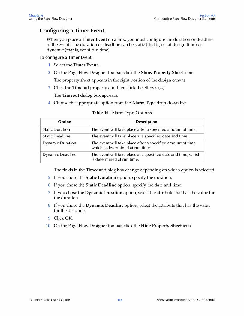
Chapter 6 Section 6.4Using the Page Flow Designer Configuring Page Flow Designer Elements
eVision Studio User’s Guide 116 SeeBeyond Proprietary and Confidential
Configuring a Timer Event
When you place a Timer Event on a link, you must configure the duration or deadline of the event. The duration or deadline can be static (that is, set at design time) or dynamic (that is, set at run time).
To configure a Timer Event
1 Select the Timer Event.
2 On the Page Flow Designer toolbar, click the Show Property Sheet icon.
The property sheet appears in the right portion of the design canvas.
3 Click the Timeout property and then click the ellipsis (...).
The Timeout dialog box appears.
4 Choose the appropriate option from the Alarm Type drop-down list.
The fields in the Timeout dialog box change depending on which option is selected.
5 If you chose the Static Duration option, specify the duration.
6 If you chose the Static Deadline option, specify the date and time.
7 If you chose the Dynamic Duration option, select the attribute that has the value for the duration.
8 If you chose the Dynamic Deadline option, select the attribute that has the value for the deadline.
9 Click OK.
10 On the Page Flow Designer toolbar, click the Hide Property Sheet icon.
Table 16 Alarm Type Options
Option Description
Static Duration The event will take place after a specified amount of time.
Static Deadline The event will take place at a specified date and time.
Dynamic Duration The event will take place after a specified amount of time, which is determined at run time.
Dynamic Deadline The event will take place at a specified date and time, which is determined at run time.

Chapter 6 Section 6.4Using the Page Flow Designer Configuring Page Flow Designer Elements
eVision Studio User’s Guide 117 SeeBeyond Proprietary and Confidential
6.4.5. Dynamic TablesThis section describes how to configure dynamic tables from the Business Rule Designer.
Mapping Data into a Dynamic Table
After you create a dynamic table in the Page Layout Designer, you map data into the table in the Page Flow Designer.
Figure 77 shows a dynamic table that will be used as an example. The first row is static. It contains two Label components that display column headings. The second row is dynamic. It contains two Text Box components.
Figure 77 Dynamic Table Example
Figure 78 shows how the dynamic table appears in the Business Rule Designer.
The logical name of this table is DynamicTable. The tr0 node represents the first row. The tr1 node represents the second row. Because the second row is dynamic, it appears within a repeating node (called repeat0). Repeating nodes are highlighted with a green, circular arrow.
Figure 78 Dynamic Table Example in the Business Rule Designer
first row
logical name of table
second row

Chapter 6 Section 6.4Using the Page Flow Designer Configuring Page Flow Designer Elements
eVision Studio User’s Guide 118 SeeBeyond Proprietary and Confidential
The td1_0 node represents the first cell in the second row. The Text Box component is called text0.
The td1_1 node represents the second cell in the second row. The Text Box component is called text1.
To populate the dynamic row, you map data from an input source (such as an Oracle database) into the appropriate nodes. In the dynamic table example, the data will be mapped into the value node of each Text Box component.
At run time, the repeating node reads data from the input source until no data is left. See Figure 79.
Figure 79 Dynamic Table Example at Run Time
Using Predicates in a Dynamic Table
You can select one row from a set of dynamically generated rows by creating a predicate.
Figure 80 shows a modified version of the dynamic table in Figure 77. The table now contains three columns. The third cell in the dynamic row contains a Radio Group component. A Submit Button component has been added below the table.
Figure 80 Dynamic Table with Radio Group Component
At run time, the user chooses one of the dynamically generated rows by selecting the radio button in the third cell. The user then clicks the Submit button.
Typically, you want to do something with the row that the user selected. For example, you could display additional information about the user’s selection in a new page. To select the row (rather than all of the dynamically generated rows), you can create a predicate in the Business Rule Designer.

Chapter 6 Section 6.4Using the Page Flow Designer Configuring Page Flow Designer Elements
eVision Studio User’s Guide 119 SeeBeyond Proprietary and Confidential
The predicate represents a condition. If the condition is met, the mappings underneath the predicate take place. In the dynamic table example, if the value of the radio button is equal to true, the radio button for this particular row is selected.
Once you create a predicate, the Business Rule Designer displays the predicate version of the repeating node immediately below the original version. You then perform the appropriate mapping from the predicate version.
You can edit or delete an existing predicate.
To create a predicate in a dynamic table
1 In the Business Rule Designer, right-click the repeating node that contains the dynamic row.
2 On the context menu, select New Predicate. The Predicate window appears.
3 Create the condition. The condition in Figure 81 states that the value of the radio button is equal to true.
Figure 81 Predicate Window
4 Click OK.
The Business Rule Designer displays the predicate version of the repeating node immediately below the original version. The syntax of the predicate appears in square brackets.
5 You can now map data from the predicate version of the repeating node.

Chapter 6 Section 6.4Using the Page Flow Designer Configuring Page Flow Designer Elements
eVision Studio User’s Guide 120 SeeBeyond Proprietary and Confidential
Figure 82 shows a repeating node that contains a Radio Group component. The data is mapped to an HTML Text component in a new page.
Figure 82 Mapping from Predicate Version of Repeating Node (Radio Group)
Figure 83 shows a repeating node that contains a Checkbox Group component. Because the user can select more than one check box at run time, this scenario differs from the Radio Group scenario. The repeating node returns repeating data. The data is mapped to a dynamic table in a new page.
Figure 83 Mapping from Predicate Version of Repeating Node (Checkbox Group)

Chapter 6 Section 6.4Using the Page Flow Designer Configuring Page Flow Designer Elements
eVision Studio User’s Guide 121 SeeBeyond Proprietary and Confidential
To edit a predicate
1 In the Business Rule Designer, right-click the predicate.
2 On the context menu, select Edit Predicate.
3 Click Yes. The Predicate window appears.
4 Make your changes.
5 Click OK.
To delete a predicate
1 In the Business Rule Designer, right-click the predicate.
2 On the context menu, select Delete Predicate.
3 Click Yes. The predicate is deleted.
Setting the Reset Destination Option
When you use predicates in a dynamic table, you might create a Page Flow in which the user can return to the Page Layout that contains the dynamic table. In this situation, you might want to “flush” the choices that the user made when the user previously accessed the Page Layout.
The following procedure describes how to set the appropriate option. Setting this option resets the values of the mapped nodes (that is, the destination) in the right side of the Business Rule Designer.
To set the Reset destination option
1 In the upper left corner of the Business Rule Designer, click the right-facing triangle. See Figure 84.
Figure 84 Displaying the Business Rules Window
The Business Rules window appears. This window lists the names of each mapping in the Business Rule Designer. See Figure 85.
click here

Chapter 6 Section 6.4Using the Page Flow Designer Configuring Page Flow Designer Elements
eVision Studio User’s Guide 122 SeeBeyond Proprietary and Confidential
Figure 85 Business Rules Window
2 Right-click the first business rule and select the Reset destination option. When this option is turned on, a check box appears next to the menu item.
3 Click the left-facing triangle. The Business Rules window closes.
6.4.6. Image ButtonsWhen you create an image button in the Page Layout Designer, the Page Flow Designer exposes the mouse coordinates of where the user clicked. The field lname.x represents the x coordinate, and the field lname.y represents the y coordinate.
Assume that:
A Page Layout called page1 contains two image buttons.
The lname property of the first image button is set to image1.
The lname property of the second image button is set to image2.
If you create a Decision element that follows the Page Layout, you can use the mouse coordinate fields to determine which image button the user clicked. You then perform the appropriate business logic.
Figure 86 shows the Page Flow for this example.
Figure 86 Page Flow for Image Button Example

Chapter 6 Section 6.4Using the Page Flow Designer Configuring Page Flow Designer Elements
eVision Studio User’s Guide 123 SeeBeyond Proprietary and Confidential
Figure 87 shows the Decision Gate Properties window for this example.
Figure 87 Decision Gate Properties Window for Image Button Example
The condition for Case 1 checks whether the x coordinate of the image1 image button contains a value. If the x coordinate contains a value, then the button was clicked and the condition evalues to TRUE.
The condition for Case 2 checks whether the x coordinate of the image2 image button contains a value. If the x coordinate contains a value, then the button was clicked and the condition evalues to TRUE.
For either condition, you can check the y coordinate instead.

Chapter 6 Section 6.5Using the Page Flow Designer Page Flow Properties
eVision Studio User’s Guide 124 SeeBeyond Proprietary and Confidential
6.5 Page Flow PropertiesEach Page Flow has a set of properties. eVision uses this information to automatically create the appropriate Page Flow attributes and input/output structures, for use in the Business Rule Designer.
To edit Page Flow properties
1 In the Project Explorer, right-click the Page Flow.
2 On the context menu, select Properties.
The Page Flow Properties dialog box appears.
3 Select one or more tabs and edit properties. For more information, see the following subsections.
6.5.1. General TabThe General tab allows you to edit general properties. See Figure 88.
Figure 88 Page Flow Properties: General Tab

Chapter 6 Section 6.5Using the Page Flow Designer Page Flow Properties
eVision Studio User’s Guide 125 SeeBeyond Proprietary and Confidential
Table 17 describes the properties.
6.5.2. Page Flow Attributes TabPage Flow Attributes are data values used by a Page Flow. They make it possible to share data between activities in a Page Flow as well as move data to and from the components that implement those activities. Complex structures such as Object Type Definitions (OTDs) and Collaborations are represented automatically in the Enterprise Explorer and are available for use in a Page Flow.
Some examples of Page Flow Attributes are:
Customer names
Addresses
Order quantities
Item descriptions
Page Flow Attributes are used to pass values between the Page Flow and external sources. You can assign Page Flow Attributes to specific activities. For example, the customer name is passed to an order process from the originating source. The customer name may be used by several of the activities in the Page Flow and is included in the Page Flow output.
eVision can pass all or part of a complex structure, or it can even assemble a composite input to a component or Web service from multiple Page Flow attributes.
To create a Page Flow attribute
1 In the Project Explorer, right-click the Page Flow.
2 On the context menu, select Properties.
3 Select the Page Flow Attributes tab.
4 Click Create.
Table 17 General Tab Properties
Property Description
Page Flow Name The name of the Page Flow.
Target Namespace The address of the Page Flow.
Persist State Indicates whether the Page Flow will be persisted using a database.
Lenient State This property applies only to Page Flows that are imported from ICAN Suite release 5.0.0, or third-party BPEL code that does not check for the presence of data before doing a copy.
If you incorrectly receive the error message No pointer for xpath: xpath, then set the value for this property to true.
Theme The look and feel of the Page Flow Designer. The default theme is BPMN.

Chapter 6 Section 6.5Using the Page Flow Designer Page Flow Properties
eVision Studio User’s Guide 126 SeeBeyond Proprietary and Confidential
The New Page Flow Attribute dialog box appears. See Figure 89.
Figure 89 New Page Flow Attribute Dialog Box
5 In the Name field, enter a name for the attribute.
6 In the Namespace field, select or browse for an existing namespace.
7 In the Type field, select one of the available types.
8 Click Add.
9 Click Close.
To edit a Page Flow attribute
1 On the Page Flow Properties dialog box, select the Page Flow Attributes tab. See Figure 90.
Figure 90 Page Flow Properties: Page Flow Attributes Tab

Chapter 6 Section 6.5Using the Page Flow Designer Page Flow Properties
eVision Studio User’s Guide 127 SeeBeyond Proprietary and Confidential
2 Select an existing attribute and do one of the following:
To rename an attribute, double click the attribute text and type a new name. Some attributes cannot be renamed.
To remove an attribute, select the attribute text and click Delete.
3 Click OK.
6.5.3. Partners TabA partner is an abstracted identification for an external system that will appear in the binding box in the Connectivity Map Editor. Multiple activities can use the same external system; therefore, multiple Activities may have the same Partner. By default, eVision assigns this identification to speed up and automate the model development.
When creating a Page Flow that will be used as a sub-process, you must create a partner and associate it with the Receive element or Receive/Reply pair. See “Invoking Another Page Flow or a Business Process” on page 141.
The Partners tab allows you to delete a partner that is not in use.
6.5.4. Correlations TabTo configure correlation, perform the following steps:
“Creating Correlation Keys” on page 127
“Adding Correlation Sets” on page 129
“Binding Correlation Sets to Page Flow Elements” on page 130
Creating Correlation Keys
A correlation key is a value that you can assign to a Page Flow, such as a Purchase Order number. The correlation key provides a way to associate and route information about specific Page Flow instances. For asynchronous message exchange between components, you must implement correlation of the instance identification. An example of when you use asynchronous message exchanges is when you create a Receive activity in the middle of a Page Flow.
To create a correlation key
1 In the Project Explorer, right-click the Page Flow.
2 On the context menu, select Properties.
3 Select the Correlations tab. See Figure 91.

Chapter 6 Section 6.5Using the Page Flow Designer Page Flow Properties
eVision Studio User’s Guide 128 SeeBeyond Proprietary and Confidential
Figure 91 Page Flow Properties: Correlations Tab
4 In the Correlation Keys section, click Create.
The New Correlation Key dialog box appears. See Figure 92.
Figure 92 New Correlation Key Dialog Box
5 Enter a Name (alias) for the correlation key.
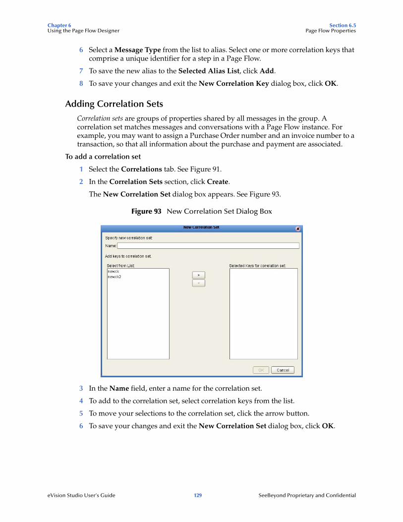
Chapter 6 Section 6.5Using the Page Flow Designer Page Flow Properties
eVision Studio User’s Guide 129 SeeBeyond Proprietary and Confidential
6 Select a Message Type from the list to alias. Select one or more correlation keys that comprise a unique identifier for a step in a Page Flow.
7 To save the new alias to the Selected Alias List, click Add.
8 To save your changes and exit the New Correlation Key dialog box, click OK.
Adding Correlation Sets
Correlation sets are groups of properties shared by all messages in the group. A correlation set matches messages and conversations with a Page Flow instance. For example, you may want to assign a Purchase Order number and an invoice number to a transaction, so that all information about the purchase and payment are associated.
To add a correlation set
1 Select the Correlations tab. See Figure 91.
2 In the Correlation Sets section, click Create.
The New Correlation Set dialog box appears. See Figure 93.
Figure 93 New Correlation Set Dialog Box
3 In the Name field, enter a name for the correlation set.
4 To add to the correlation set, select correlation keys from the list.
5 To move your selections to the correlation set, click the arrow button.
6 To save your changes and exit the New Correlation Set dialog box, click OK.

Chapter 6 Section 6.5Using the Page Flow Designer Page Flow Properties
eVision Studio User’s Guide 130 SeeBeyond Proprietary and Confidential
Binding Correlation Sets to Page Flow Elements
When you use one or more correlation sets in a Page Flow, the values must be initialized at some point. If the user chooses to initialize the set within an Activity, they will also identify which Page Flow Attribute will be used (or both).
To bind correlation sets to Page Flow elements
1 Select a Page Flow element.
2 On the Page Flow Designer toolbar, click the Show Property Sheet icon. The properties window appears in the right portion of the design canvas. See Figure 94.
Figure 94 Page Flow Element Properties Window
3 Locate the Use Correlations property and click the no field.
4 In the no field, click the Command (...) button. The Use Correlations dialog box appears.
5 Click Add. The Assign Correlation Set dialog box appears.
6 In the left pane, select the correlation set that you want to add to the Page Flow element.
7 Click the arrow button to move it to Selected Correlation Set(s) area.
8 Click OK.
9 In the Use Correlations dialog box, click OK.
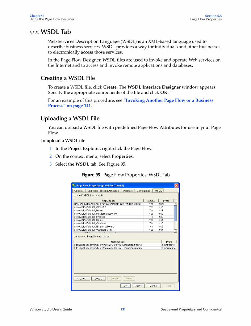
Chapter 6 Section 6.5Using the Page Flow Designer Page Flow Properties
eVision Studio User’s Guide 131 SeeBeyond Proprietary and Confidential
6.5.5. WSDL TabWeb Services Description Language (WSDL) is an XML-based language used to describe business services. WSDL provides a way for individuals and other businesses to electronically access those services.
In the Page Flow Designer, WSDL files are used to invoke and operate Web services on the Internet and to access and invoke remote applications and databases.
Creating a WSDL File
To create a WSDL file, click Create. The WSDL Interface Designer window appears. Specify the appropriate components of the file and click OK.
For an example of this procedure, see “Invoking Another Page Flow or a Business Process” on page 141.
Uploading a WSDL File
You can upload a WSDL file with predefined Page Flow Attributes for use in your Page Flow.
To upload a WSDL file
1 In the Project Explorer, right-click the Page Flow.
2 On the context menu, select Properties.
3 Select the WSDL tab. See Figure 95.
Figure 95 Page Flow Properties: WSDL Tab

Chapter 6 Section 6.6Using the Page Flow Designer Persisting Page Flows
eVision Studio User’s Guide 132 SeeBeyond Proprietary and Confidential
4 Click Load.
The Load WSDL dialog box appears. See Figure 96.
Figure 96 Load WSDL Dialog Box
5 To specify the location of your WSDL, select URL or File.
6 In the text field, type the path to the WSDL file.
7 Click UPLOAD.
6.6 Persisting Page FlowsIf you are using eVision in conjunction with eInsight to allow users to perform workflow tasks, then persisting Page Flows helps to ensure recoverability across the entire project.
eVision supports the following databases:
Oracle 8.1.7, 9.1, and 9.2
Sybase 12.5
Microsoft SQL Server 2000
IBM DB2 Universal Database 8.1
The procedure for setting up eVision persistence is the same as the procedure for setting up eInsight persistence. See the eInsight Business Process Manager User’s Guide for detailed instructions. This section provides a summary of the instructions.
6.6.1 Configuration SummaryeVision provides an install script and an uninstall script for each supported database. These scripts appear in the Project Explorer of Enterprise Designer. See Figure 97.

Chapter 6 Section 6.7Using the Page Flow Designer Page Flows in Connectivity Maps
eVision Studio User’s Guide 133 SeeBeyond Proprietary and Confidential
Figure 97 Database Install and Uninstall Scripts
You check out the database scripts from the Version Control system, specify connection information for the database, open the install script and change default values (if necessary), and then run the script. The appropriate tables are created in the database.
Page Flows include a property called Persist State. You set this property to yes. This action causes a database scripts folder to appear under the Page Flow. These scripts are similar to the scripts shown in Figure 97. Once again, you run the install script. The appropriate tables are created in the database.
Additional steps are required for the eInsight Worklist Viewer.
6.7 Page Flows in Connectivity MapsWhen you create the Connectivity Map for a Project that contains one or more Page Flows, you add each Page Flow in the Project to a Service. You then link each Service to a Web Connector.
6.7.1. Adding Each Page Flow to a ServiceFor each Page Flow in the Project, create a Service and then drag the Page Flow from the Project Explorer into the Service. The red gears in the Service change to a Page Flow symbol. See Figure 98.
Figure 98 Change in Appearance of Service
Before Page Flow is added
After Page Flow is added

Chapter 6 Section 6.7Using the Page Flow Designer Page Flows in Connectivity Maps
eVision Studio User’s Guide 134 SeeBeyond Proprietary and Confidential
As a shortcut, you can drag the Page Flow from the Project Explorer onto a blank area of the design canvas. This action automatically creates a Service. The Service name is based on the Page Flow name.
6.7.2. Linking Each Service to a Web ConnectorThe Web Connector is a logical representation of the Web container in which an eVision Studio Web application runs.
Drag a Web Connector from the Connectivity Map Editor toolbar onto the canvas. Double-click each Service that contains a Page Flow. A binding box appears. Link the WSPProvider Implemented Service to the Web Connector. Link the eVision_user Invoked Service to the Web Connector. See Figure 99.
Figure 99 Service Binding Box
Implemented Services represent the Web services that are implemented and thus served by the Page Flow. The WSPProvider service is the entry point (the home page) of the Web application.
Invoked Services represent the Web services that are called by the Page Flow.
When you minimize the binding box, the connectors appear crossed. This behavior is normal. In addition, a connection icon appears on the link. See Figure 100.
Figure 100 Linked Service and Web Connector
connection icon

Chapter 6 Section 6.7Using the Page Flow Designer Page Flows in Connectivity Maps
eVision Studio User’s Guide 135 SeeBeyond Proprietary and Confidential
The Web application consists of a presentation component and a back-end component. To configure properties for the presentation component of the application, open the binding box and double-click the connection icon between the WSPProvider Implemented Service and the Web Connector. The Properties dialog box appears.
Figure 101 Web Connector Configuration Properties
Chapter 9, “Authentication and Error Handling” describes the following properties:
auth-method
form-login-error-page
form-login-page
http-401-error-page
http-403-error-page
http-404-error-page
http-500-error-page
“Application URL” on page 136 describes the servlet-context property.
The session-timeout property is expressed in a whole number of minutes.
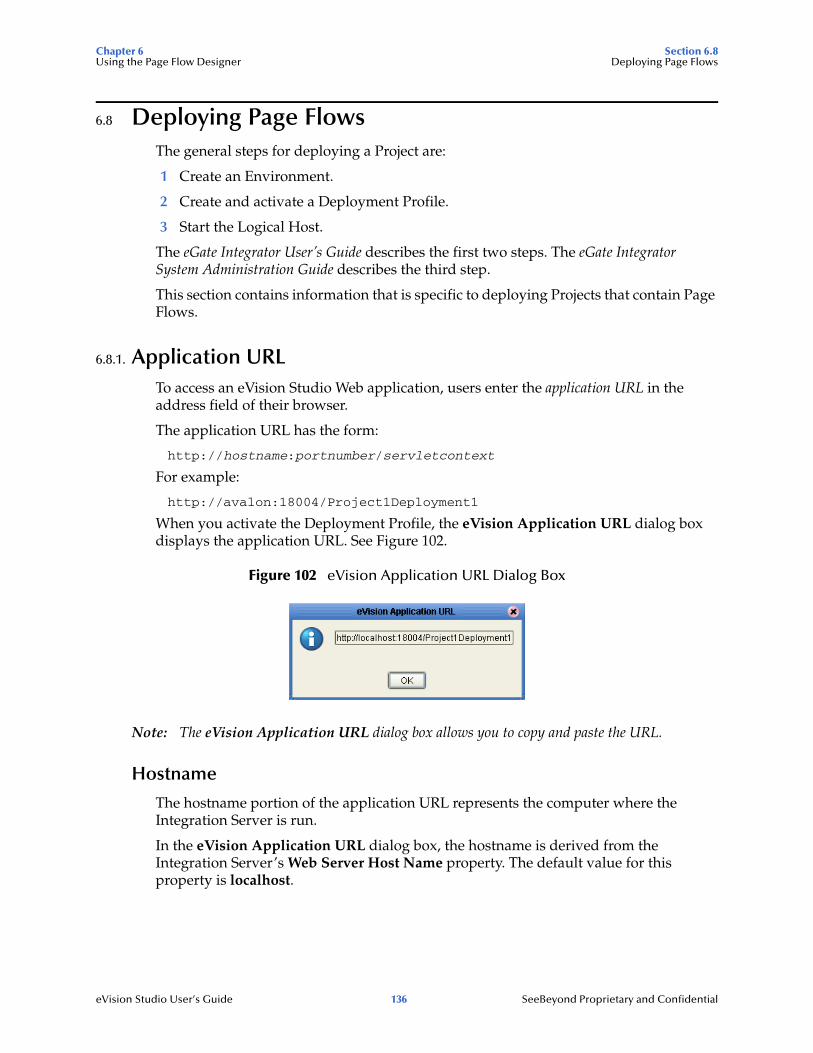
Chapter 6 Section 6.8Using the Page Flow Designer Deploying Page Flows
eVision Studio User’s Guide 136 SeeBeyond Proprietary and Confidential
6.8 Deploying Page FlowsThe general steps for deploying a Project are:
1 Create an Environment.
2 Create and activate a Deployment Profile.
3 Start the Logical Host.
The eGate Integrator User’s Guide describes the first two steps. The eGate Integrator System Administration Guide describes the third step.
This section contains information that is specific to deploying Projects that contain Page Flows.
6.8.1. Application URLTo access an eVision Studio Web application, users enter the application URL in the address field of their browser.
The application URL has the form:
http://hostname:portnumber/servletcontext
For example:
http://avalon:18004/Project1Deployment1
When you activate the Deployment Profile, the eVision Application URL dialog box displays the application URL. See Figure 102.
Figure 102 eVision Application URL Dialog Box
Note: The eVision Application URL dialog box allows you to copy and paste the URL.
Hostname
The hostname portion of the application URL represents the computer where the Integration Server is run.
In the eVision Application URL dialog box, the hostname is derived from the Integration Server’s Web Server Host Name property. The default value for this property is localhost.

Chapter 6 Section 6.8Using the Page Flow Designer Deploying Page Flows
eVision Studio User’s Guide 137 SeeBeyond Proprietary and Confidential
If the Integration Server is run on a computer other than the local host, then the hostname in the eVision Application URL dialog box will not be correct. However, users will still be able to access the Web application using the hostname of the computer where the Integration Server is run.
If you want to ensure that the eVision Application URL dialog box displays the correct hostname, perform the following steps before activating the Deployment Profile:
1 In the Environment Explorer of Enterprise Designer, right-click the Integration Server.
2 On the context menu, select Properties.
3 Expand the tree and select Web Container Configuration. See Figure 103.
Figure 103 Integration Server Properties - Web Container Configuration
4 Set the value of the Web Server Host Name property to the hostname of the computer where the Integration Server is run.
5 Click OK.
Servlet Context
The default value of the servlet context is the Project name concatenated with the Deployment Profile name. If you want to change the servlet context to a more user-friendly value, perform the following steps before activating the Deployment Profile:
1 In the Connectivity Map Editor, open the Service binding box and double-click the connection icon between the WSPProvider Implemented Service and the Web Connector.
2 Change the value of the servlet-context property.
3 Click OK.

Chapter 6 Section 6.8Using the Page Flow Designer Deploying Page Flows
eVision Studio User’s Guide 138 SeeBeyond Proprietary and Confidential
Multiple Web Applications
eVision support multiple Web applications in the same deployment. See Figure 104.
Figure 104 Connectivity Map with Multiple Web Applications
You must configure each application to have a different URL. To do this, open the connection icons and ensure that the servlet-context properties have different values. See Figure 105.
Figure 105 servlet-context Properties for Multiple Web Applications
If you do not perform this step, then the generated Web application will not deploy, because multiple .war files will conflict with the same servlet context.
Chapter 6 Section 6.8Using the Page Flow Designer Deploying Page Flows
eVision Studio User’s Guide 139 SeeBeyond Proprietary and Confidential
6.8.2. Manually Passing in ParametersYou can add one or more parameters to an application URL. The Page Flow can be designed to make a decision based on the value of a parameter. Because the value may differ among invocations, the same Page Flow may be invoked with different URLs.
Home Page
If you want to pass one or more parameters into the home page, add the following text before each parameter name:
input_link_Message_u002F_Input_u002F_
Note: The characters u002F represent a forward slash (/) in Unicode.
The following example passes one parameter into the home page. The URL appears on multiple lines for readability.
http://myhostname:18004/Project1Deployment1?input_link_Message_u002F_Input_u002F_username=bill
Non-Home Page
If you want to pass one or more parameters into a Page Layout other than the home page, then you must also add the following text after the servlet context. In the port type, LinkName refers to the Page Link that points to the Page Layout.
input_link_Message_u002F_Input_u002F_PortType={urn:ProjectName_LinkName}link&input_link_Message_u002F_Input_u002F_Operation=link&
The following example passes one parameter into a Page Layout other than the home page. The URL appears on multiple lines for readability.
http://myhostname:18004/Project1Deployment1?input_link_Message_u002F_Input_u002F_PortType={urn:Project1_link3}link&input_link_Message_u002F_Input_u002F_Operation=link&input_link_Message_u002F_Input_u002F_username=bill

Chapter 6 Section 6.8Using the Page Flow Designer Deploying Page Flows
eVision Studio User’s Guide 140 SeeBeyond Proprietary and Confidential
6.8.3. eVision External SystemWhen you create the Environment, you must include an eVision External System. The eVision External System is a logical representation of the Web container in which an eVision Studio Web application runs. It is where the presentation component of the application will execute.
When you create the Deployment Profile, some of the components in the left panel of the Deployment Profile Editor will contain a Web Connector. You can click the Auto Map icon, or you can manually drag these components into the eVision External System.
Figure 106 shows Web Connector components that have been deployed to an eVision External System.
Figure 106 Web Connector Components in eVision External System
The eVision External System contains a user-role property, which is used in authentication. For more information, see Chapter 9, “Authentication and Error Handling”.
6.8.4. SSL SupportYou can configure an eVision Web application to use the Secure Sockets Layer (SSL), which is designed to protect communication between clients and servers over the Internet. The protocol portion of the application URL will be https instead of http.
For detailed instructions, see the “Configuring a SeeBeyond Integration Server to Use SSL” section in the eGate Integrator System Administration Guide.

Chapter 6 Section 6.9Using the Page Flow Designer Invoking Another Page Flow or a Business Process
eVision Studio User’s Guide 141 SeeBeyond Proprietary and Confidential
6.9 Invoking Another Page Flow or a Business ProcessFrom within a Page Flow, you can invoke another Page Flow or an eInsight Business Process. The latter scenario assumes that you have installed eInsight Business Process Manager.
This feature lets you create reusable Page Flows and Business Processes.
In the following procedures, you create a Web service operation in the child Page Flow or Business Process, and then configure the parent Page Flow to call the operation.
To create the placeholder elements
1 In the parent Page Flow, create an empty Activity element as a placeholder for the child Page Flow or Business Process. See Figure 107.
Figure 107 Parent Page Flow - Empty Activity
In a later step, you will drag a Web service operation into this element.
2 In the child Page Flow or Business Process, create an empty Receive element at the beginning and an empty Reply element at the end. See Figure 108.
Figure 108 Child Page Flow - Empty Receive and Reply
To configure the child Page Flow or Business Process
1 In the Project Explorer, right-click the child Page Flow or Business Process and select Properties.
The Page Flow Properties dialog box appears.
2 Create a Page Flow Attribute, which will be used to move data betwen the parent Page Flow and the child Page Flow or Business Process:
A Select the Page Flow Attributes tab.
B Click Create. The New Page Flow Attribute dialog box appears.
C In the Name field, enter a name for the attribute (for example, String).
D In the Namespace field, select the namespace that begins with SimpleDataTypes.
E In the Type field, select one of the available types (for example, String).
F Click Add, and then click Close.
G Click Apply.

Chapter 6 Section 6.9Using the Page Flow Designer Invoking Another Page Flow or a Business Process
eVision Studio User’s Guide 142 SeeBeyond Proprietary and Confidential
3 Create a partner, which will appear in the Service binding boxes in the Connectivity Map:
A Select the Partners tab.
B Click New.
C If desired, change the partner name to a more descriptive name.
D Click Apply.
4 Create a WSDL file, which will define the Web service that the parent Page Flow calls:
A Select the WSDL tab.
B Click Create. The WSDL Interface Designer window appears.
C Click PortType. A port type contains one or more operations that a Web service performs. This port type will contain one operation.
D Click Operation. An operation is similar to a function or method.
E Click Input. The input represents the data that the parent Page Flow sends to the operation.
F In the Properties area, select the Page Flow Attribute that you defined in step 2.
G In the WSDL Definition area, select the operation that you just created.
H Click Output. The output represents the data that the child Page Flow or Business Process sends back to the parent Page Flow.
I In the Properties area, select the Page Flow Attribute that you defined in step 2.
Figure 109 WSDL Interface Designer Window
J Click OK.
K Click Apply.
5 Click OK.
The Page Flow Properties dialog box closes.

Chapter 6 Section 6.9Using the Page Flow Designer Invoking Another Page Flow or a Business Process
eVision Studio User’s Guide 143 SeeBeyond Proprietary and Confidential
6 Specify properties for the Receive and Reply elements:
A On the Page Flow Designer toolbar, click the Show Property Sheet icon.
B Click the Receive element. This element receives the invocation from the parent Page Flow.
C Select the partner that you created earlier, as well as the port type, operation, and output.
D Click the Reply element. This element provides a response to the parent Page Flow.
E Select the partner that you created earlier, as well as the port type, operation, and input.
Note: If the child Page Flow or Business Process is to be invoked as a synchronous request/reply Web service, then the Receive and Reply elements must have the same partner, port type, and operation.
F On the Page Flow Designer toolbar, click the Hide Property Sheet icon.
7 On the File menu, click Save.
8 Add one or more business rules and perform the appropriate mappings in the Business Rule Designer.
To configure the parent Page Flow
1 Display the parent Page Flow.
2 From the Project Explorer, select the operation that you created under the child Page Flow or Business Process and drag it onto the empty Activity in the parent Page Flow. See Figure 110.
Figure 110 Parent Page Flow - Activity Invokes Child Operation
3 Add one or more business rules and perform the appropriate mappings in the Business Rule Designer.
To create the Connectivity Map
When you create the Connectivity Map, note the following:
The Invoked Services box in the parent Page Flow contains the partner that you created earlier.
The Implemented Services box in the child Page Flow or Business Process contains the partner that you created earlier.
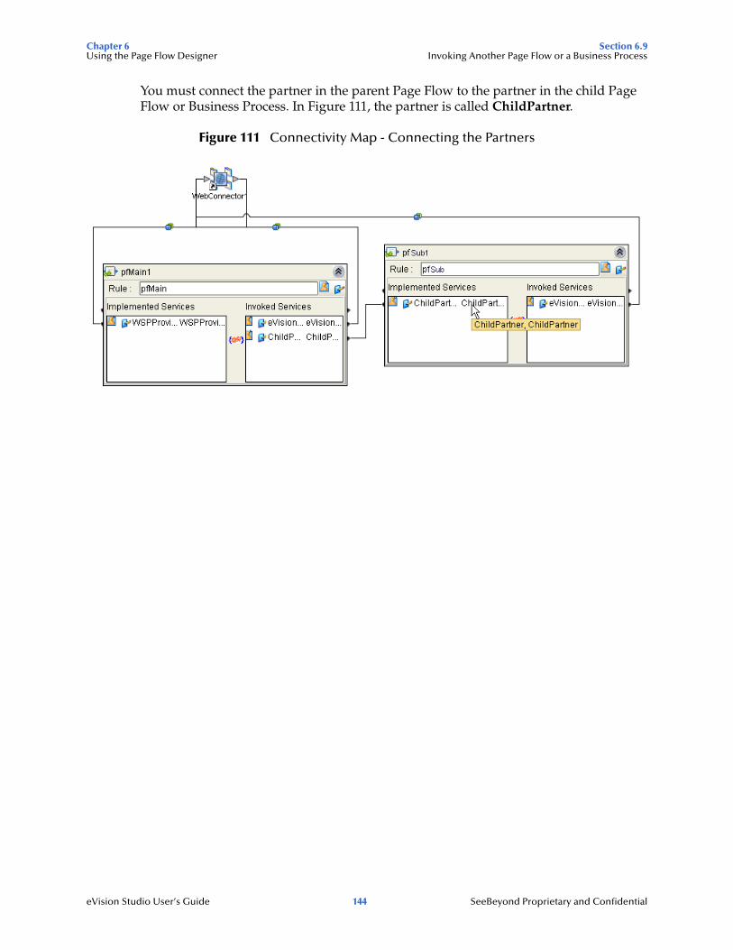
Chapter 6 Section 6.9Using the Page Flow Designer Invoking Another Page Flow or a Business Process
eVision Studio User’s Guide 144 SeeBeyond Proprietary and Confidential
You must connect the partner in the parent Page Flow to the partner in the child Page Flow or Business Process. In Figure 111, the partner is called ChildPartner.
Figure 111 Connectivity Map - Connecting the Partners

Chapter 7 Section 7.1Page Flow Designer Tutorial Tutorial Overview
eVision Studio User’s Guide 145 SeeBeyond Proprietary and Confidential
Chapter 7
Page Flow Designer Tutorial
This chapter guides you through the process of creating and deploying an eVision Studio Web application.
What’s in This Chapter
“Tutorial Overview” on page 145
“Downloading the Sample Project” on page 146
“Importing the Sample Project into the Repository” on page 147
“Checking Out the Project Components” on page 148
“Creating the Page Flow” on page 148
“Creating the Connectivity Map” on page 162
“Creating the Environment” on page 163
“Creating and Activating the Deployment Profile” on page 164
“Running and Testing the Application” on page 166
“Importing the Working Sample Project” on page 168
7.1 Tutorial OverviewIn the following tutorial, you import, assemble, and run the sample Web application that is packaged with eVision Studio. Going through the Page Flow creation process allows you to work with several of the most-used Page Flow Designer tools while assembling the necessary components to complete a Web application that you can deploy, then run on the Logical Host, and access with your browser.

Chapter 7 Section 7.2Page Flow Designer Tutorial Downloading the Sample Project
eVision Studio User’s Guide 146 SeeBeyond Proprietary and Confidential
Figure 112 shows the Page Flow Designer view of the sample application, which allows employees to request vacation time.
Figure 112 Page Flow Designer View of Sample Application
7.2 Downloading the Sample ProjectDownload the sample project only if you have not already done so. If you created the sample Web page as described in Chapter 5, “Page Flow Designer Tutorial”, then you already downloaded the files. Skip to “Importing the Sample Project into the Repository” on page 147.
The sample project is provided in .zip file format. It is included in the eVision Studio documentation .sar file. The first step in this tutorial is to download the sample project from the Repository.
The Repository must be running before you can use Enterprise Manager or Enterprise Designer. The first step of any procedure is to make sure that the Repository is running. The SeeBeyond ICAN Suite Installation Guide describes how to start the Repository.
To download the sample project
1 Start Internet Explorer.
2 In the Address field, enter http://hostname:portnumber
where
hostname is the TCP/IP host name of the server where the Repository is installed.
portnumber is the base port number of the Repository.
The SeeBeyond Customer Login window of Enterprise Manager appears.
3 Enter your username and password.
4 Click Login.
The Enterprise Manager home page appears.
5 Click the DOCUMENTATION tab.
6 In the left frame of the Documentation page, click eVision Studio.

Chapter 7 Section 7.3Page Flow Designer Tutorial Importing the Sample Project into the Repository
eVision Studio User’s Guide 147 SeeBeyond Proprietary and Confidential
Note: If you do not see an eVision Studio link in the left frame, then the eVision Studio Documentation .sar file must be uploaded. See Chapter 3, “Installing eVision Studio” on page 26.
7 In the right frame of the Documentation page, click Download Sample.
8 Using an archive utility (such as WinZip), extract the sample files to a folder on your computer. Remember where you saved the files. If you use the folder names stored in the archive, the sample files will be stored in a directory called eVision_Sample.
The eVisionSampleComponents.zip file contains the pre-built Web pages that you will use to create the sample application.
The eVisionTutorial_sample.zip file is for reference and analysis after you successfully build the sample application from the pre-built components.
7.3 Importing the Sample Project into the RepositoryYou import the eVisionSampleComponents.zip Project using Enterprise Designer. Make sure that the Repository is running before you start Enterprise Designer.
Note: Do not import the eVisionTutorial_sample.zip Project until you finish this tutorial.
To import the sample project into the Repository
1 Start Enterprise Designer.
2 In the Project Explorer, right click the Repository.
3 On the context menu, select Import. The Import dialog box prompts you to save any changes to other Projects.
4 Assuming that you have saved any changes to other Projects, click Yes. Import Manager appears.
5 Click Browse and navigate to the folder that contains the extracted sample files.
6 Select eVisionSampleComponents.zip and click Open.
7 Click Import.
When the import process is finished, a confirmation message appears.
8 Click OK and then click Close. The Repository refreshes.
9 In the Project Explorer, expand the eVisionSampleComponents Project. The Project contains a Page Link, five Page Layouts, and two image files. See Figure 113.

Chapter 7 Section 7.4Page Flow Designer Tutorial Checking Out the Project Components
eVision Studio User’s Guide 148 SeeBeyond Proprietary and Confidential
Figure 113 Sample Project Components in Project Explorer
7.4 Checking Out the Project ComponentsThe icon for each component includes a red lock, which means that the component is checked into the Version Control system. Before you can use the components, you must check them out one at a time.
To check out the Project components
1 In the Project Explorer, under eVisionSampleComponents, right-click the Home Page Link.
2 On the context menu, click Check Out. The Version Control - Check Out dialog box appears.
3 Click OK. The red lock disappears, and a writing pad icon appears.
4 Repeat these steps for each component.
Note: When you check out the two image files, the red lock disappears. However, a writing pad icon does not appear.
7.5 Creating the Page FlowThis section describes how to assemble the eVision components to create a Page Flow.
Because the Page Link and the Page Layouts are provided in the sample project, you do not need to create them.

Chapter 7 Section 7.5Page Flow Designer Tutorial Creating the Page Flow
eVision Studio User’s Guide 149 SeeBeyond Proprietary and Confidential
You will use elements in the Page Flow Designer’s toolbar to connect the components in a Page Flow. Chapter 6, “Using the Page Flow Designer” describes the elements in detail. See Figure 114.
Figure 114 Page Flow Designer Toolbar
Table 18 describes the Page Layouts in the sample project. You can open each Page Layout and examine it. However, do not modify any of the Page Layouts.
7.5.1 Adding a Page Flow to the ProjectYou must first add a Page Flow to the Project.
To add a Page Flow to the Project
1 In the Project Explorer, right-click eVisionSampleComponents.
2 On the context menu, click New, and then select Page Flow.
A new Page Flow icon appears in the Project Explorer tree under eVisionSampleComponents, and a blank Page Flow appears on the Page Flow Designer canvas (the right pane of Enterprise Designer). The default name is PageFlow1. A new Page Flow always contains a Start element and an End element.
7.5.2 Adding the Page Flow ElementsIn this procedure, you add the Page Flow elements to the Page Flow.
To add the initial Page Flow elements
1 In the Project Explorer, expand the Home Page Link.
2 From the Project Explorer, drag the Home.link operation onto the canvas.
Place the Home.link icon to the right of and below the Start element.
Table 18 Page Layouts in Sample Project
Page Layout Description
ClosePF Indicates that the vacation request has been submitted. The user can exit the application.
Continue Enables the user to continue or exit.
InputEmployeeInfo Enables the user to enter his or her name and employee number, and then click a Request Vacation button.
Reject Indicates that authorization of the employee information failed. The user can click a button to try again.
VacationForm Enables the user to enter the number of vacation days and the manager’s e-mail address, and then click a Submit button.

Chapter 7 Section 7.5Page Flow Designer Tutorial Creating the Page Flow
eVision Studio User’s Guide 150 SeeBeyond Proprietary and Confidential
3 From the Page Flow Designer toolbar, drag a Business Rule element onto the canvas.
Place the Business Rule element to the right of and below the Home.link icon.
4 From the Page Flow Designer toolbar, drag a While element onto the canvas.
Place the While icon between the Business Rule element and the End element.
5 Double-click the While icon to expand it.
6 Check your progress. The Page Flow should look like the example in Figure 115.
Figure 115 Initial Page Flow Elements
To add the Page Flow elements inside the While loop
1 From the Project Explorer, drag the InputEmployeeInfo.show operation onto the canvas.
Without releasing the mouse button, place the InputEmployeeInfo.show icon to the far left inside the While Loop boundaries.
Caution: Do not place the icon outside of the While Loop and then drag the icon inside the While Loop.
2 On the Page Flow Designer toolbar, click the Branching Activities icon. On the drop-down menu, click Decision, and drag the Decision element onto the canvas.
Without releasing the mouse button, place the Decision element to the right of and aligned with the InputEmployeeInfo.show icon inside the While loop.
Two icons appear: Decision and Decision.end.
3 Move the Decision.end icon to the right so that you have enough room to place two icons between Decision and Decision.end. Notice how the While loop becomes wider.
4 From the Page Flow Designer toolbar, drag a Business Rule element onto the canvas.
Without releasing the mouse button, place the Business Rule element to the right of and aligned with the Decision element inside the While loop.

Chapter 7 Section 7.5Page Flow Designer Tutorial Creating the Page Flow
eVision Studio User’s Guide 151 SeeBeyond Proprietary and Confidential
5 From the Project Explorer, drag the VacationForm.show operation onto the canvas.
Without releasing the mouse button, place the VacationForm.show icon to the right of and aligned with the Business Rule element inside the While loop.
6 From the Project Explorer, drag the Continue.show operation onto the canvas.
Without releasing the mouse button, place the Continue.show icon to the right of and aligned with the Decision.end element inside the While loop.
7 From the Project Explorer, drag the Reject.show operation onto the canvas.
Without releasing the mouse button, place the Reject.show icon above the other elements and center it in the While loop. Notice how the While loop becomes taller.
8 Check your progress. The While loop should look like the example in Figure 116.
Figure 116 Page Flow Elements Inside the While Loop
To add the final Page Flow element
1 From the Project Explorer, drag the ClosePF.show operation onto the canvas.
Place the ClosePF.show icon between the While loop and the End element.
2 Check your progress. The Page Flow should look like the example in Figure 117.
Figure 117 Unconnected Page Flow Components

Chapter 7 Section 7.5Page Flow Designer Tutorial Creating the Page Flow
eVision Studio User’s Guide 152 SeeBeyond Proprietary and Confidential
7.5.3 Connecting the Page Flow ElementsIn this procedure, you link the Page Flow elements that you added to the Page Flow.
To connect the Page Flow elements
1 Place your mouse pointer over the arrow on the right edge of the Start icon until the pointer changes to the hand symbol.
2 Click and drag a connection line onto the Home.link element and release the mouse button.
3 Proceeding from left to right, connect all of the Page Flow components. See Figure 118.
Note that the Decision element has two branching links. To ensure that Case 1 is on the top and Case 2 is on the bottom, create the link between the Decision element and the Reject.show icon and then create the link between the Decision element and the Business Rule element.
Figure 118 Connected Page Flow Components
4 On the File menu, click Save All.
7.5.4 Configuring the First Business Rule ElementIn the following procedures, you use the Business Rule Designer to configure relationships between Output and Input Attributes. The Business Rule Designer consists of three panes:
Output (on the left)
Mapper (in the center)
Input (on the right)
To configure the first Business Rule element
1 On the Page Flow Designer toolbar, click the Display Business Rule Designer icon. See Figure 119.

Chapter 7 Section 7.5Page Flow Designer Tutorial Creating the Page Flow
eVision Studio User’s Guide 153 SeeBeyond Proprietary and Confidential
Figure 119 Displaying the Business Rule Designer
The Business Rule Designer appears in the lower pane of the Page Flow Designer.
2 On the Page Flow Designer canvas, select the Business Rule element that resides outside and to the left of the While loop.
Caution: Do not select the Business Rule element that resides inside the While loop.
The Business Rule Designer is populated with Output and Input Attributes.
3 In the Business Rule Designer Input pane (the right pane), expand Continue.show.Output to expose the radiogroup0 node.
The radiogroup0 node represents the Radio Group component in the Continue Page Layout. radiogroup0 is the value of the component’s lname property.
4 Expand the radiogroup0 node to expose the value element.
5 From the Business Rule Designer Method Palette, click the String menu and drag the string literal icon onto the Mapper. The Input dialog box appears.
6 In the Enter a Literal Value box, type yes. Make sure that the text is lower-case.
7 Click OK.
8 Select the string literal container within the yes box, drag it into the Input pane, and drop it onto the value element. See Figure 120.
Figure 120 Mapping a String Literal
Display Business Rule Designer
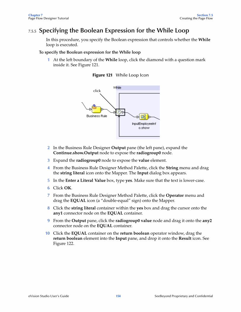
Chapter 7 Section 7.5Page Flow Designer Tutorial Creating the Page Flow
eVision Studio User’s Guide 154 SeeBeyond Proprietary and Confidential
7.5.5 Specifying the Boolean Expression for the While LoopIn this procedure, you specify the Boolean expression that controls whether the While loop is executed.
To specify the Boolean expression for the While loop
1 At the left boundary of the While loop, click the diamond with a question mark inside it. See Figure 121.
Figure 121 While Loop Icon
2 In the Business Rule Designer Output pane (the left pane), expand the Continue.show.Output node to expose the radiogroup0 node.
3 Expand the radiogroup0 node to expose the value element.
4 From the Business Rule Designer Method Palette, click the String menu and drag the string literal icon onto the Mapper. The Input dialog box appears.
5 In the Enter a Literal Value box, type yes. Make sure that the text is lower-case.
6 Click OK.
7 From the Business Rule Designer Method Palette, click the Operator menu and drag the EQUAL icon (a “double-equal” sign) onto the Mapper.
8 Click the string literal container within the yes box and drag the cursor onto the any1 connector node on the EQUAL container.
9 From the Output pane, click the radiogroup0 value node and drag it onto the any2 connector node on the EQUAL container.
10 Click the EQUAL container on the return boolean operator window, drag the return boolean element into the Input pane, and drop it onto the Result icon. See Figure 122.
click

Chapter 7 Section 7.5Page Flow Designer Tutorial Creating the Page Flow
eVision Studio User’s Guide 155 SeeBeyond Proprietary and Confidential
Figure 122 Boolean Expression for the While Loop
7.5.6 Configuring the Decision LogicA Decision Gate element must have its properties defined such that, based on incoming events, there can be two or more path possibilities within the Page Flow. In this procedure, you define properties for a Decision Gate element that contains two cases.
Opening the Decision Gate Properties Window
You configure the decision logic from the Decision Gate Properties window.
To open the Decision Gate Properties window
1 On the Page Flow Designer canvas, double-click the Decision element inside the While loop. See Figure 123.
Figure 123 Decision Element in While Loop
The Decision Gate Properties window appears. See Figure 124.
double-click

Chapter 7 Section 7.5Page Flow Designer Tutorial Creating the Page Flow
eVision Studio User’s Guide 156 SeeBeyond Proprietary and Confidential
Figure 124 Decision Gate Properties Window
2 Under the Order of Execution heading, click Case 1 to activate the Mapper.
3 When you define the properties for Case 1, you use the greater than function on the Operator menu. If the greater than function does not currently appear on the Operator menu, perform the following steps:
A On the Operator menu, click Settings. The Method Palette dialog box appears.
B Ensure that the Operator tab is selected. See Figure 125.
Figure 125 Method Palette Dialog Box with Operator Tab Selected
Operator tab
greater than function

Chapter 7 Section 7.5Page Flow Designer Tutorial Creating the Page Flow
eVision Studio User’s Guide 157 SeeBeyond Proprietary and Confidential
C Click the greater than check box.
D Click Close.
Defining the Properties for Case 1
Case 1 is triggered when the user enters an invalid employee number in the InputEmployeeInfo Page Layout. Any number greater than 5000 is invalid.
To define the properties for Case 1
1 Click the String menu and drag the string literal icon onto the Mapper. The Input dialog box appears.
2 In the Enter a Literal Value box, type 5000. This number represents the highest valid employee number.
3 Click OK.
4 Click the Operator menu and drag the greater than icon onto the Mapper.
5 In the Output pane (the left pane) of the Decision Gate Properties window, expand the InputEmployeeInfo.show.Output node until the EmpNumber node appears.
The EmpNumber node represents the text box to the right of the Enter Employee Number label in the InputEmployeeInfo Page Layout. EmpNumber is the value of the text box component’s lname property.
6 Drag the EmpNumber node onto the Mapper and, on the greater than container, drop it onto the any1 node.
7 Click the string literal container near the right of the value box (the value is 5000) and, on the greater than container, drop it onto the any2 node.
8 Click the greater than container near the right of the return boolean box, drag it into the Input pane (the right pane), and drop it onto the Result icon. See Figure 126.

Chapter 7 Section 7.5Page Flow Designer Tutorial Creating the Page Flow
eVision Studio User’s Guide 158 SeeBeyond Proprietary and Confidential
Figure 126 Defining Decision Gate Properties - Case 1
Defining the Properties for Case 2
Case 2 is triggered when the user enters a valid employee number in the InputEmployeeInfo Page Layout. Any number less than or equal to 5000 is valid.
To define the properties for Case 2
1 Under the Order of Execution heading, click Case 2.
2 In the Output pane (the left pane), click the vacationRequest node under the InputEmployee.show.Output node.
The vacationRequest node represents the Request Vacation button in the InputEmployeeInfo Page Layout. vacationRequest is the value of the component’s lname property.
3 Click the vacationRequest node, drag it into the Input pane (the right pane), and drop it onto the Result icon. See Figure 127.

Chapter 7 Section 7.5Page Flow Designer Tutorial Creating the Page Flow
eVision Studio User’s Guide 159 SeeBeyond Proprietary and Confidential
Figure 127 Defining Decision Gate Properties - Case 2
4 Click Apply.
5 Click OK. The Decision Gate Properties window closes.
7.5.7 Mapping the Employee Name to the Vacation FormIn this procedure, you map the employee name that the user entered in the InputEmployeeInfo Page Layout to the VacationForm Page Layout. This mapping helps to personalize the Web application.
To map the employee name to the vacation form
1 On the Page Flow Designer canvas, click the Business Rule element inside the While loop. See Figure 128.
Figure 128 Business Rule Element in the While Loop

Chapter 7 Section 7.5Page Flow Designer Tutorial Creating the Page Flow
eVision Studio User’s Guide 160 SeeBeyond Proprietary and Confidential
2 In the Business Rule Designer Output pane (the left pane), expand the InputEmployeeInfo.show.Output node to expose the EmpName node.
The EmpName node represents the text box to the right of the Enter Name label in the InputEmployeeInfo Page Layout. EmpName is the value of the text box component’s lname property.
3 In the Business Rule Designer Input pane (the right pane), expand the VacationForm.show.Input node to expose the empName text node.
The empName node represents the upper HTML Text component in the VacationForm Page Layout. empName is the value of the component’s lname property.
4 Click the EmpName node, drag it onto the Input pane, and drop it onto the text node. See Figure 129.
Figure 129 Mapping the Employee Name to the Vacation Form
7.5.8 Restoring the Input ValuesThis is the last mapping procedure. In the Web application, when the user returns to the InputEmployeeInfo Page Layout, the input values are restored.
To restore the input values
1 On the Page Flow Designer canvas, right-click the connector between the Continue.show page and the While loop.
2 On the context menu, click Add Business Rule. See Figure 130.
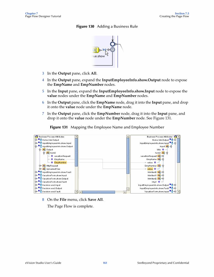
Chapter 7 Section 7.5Page Flow Designer Tutorial Creating the Page Flow
eVision Studio User’s Guide 161 SeeBeyond Proprietary and Confidential
Figure 130 Adding a Business Rule
3 In the Output pane, click All.
4 In the Output pane, expand the InputEmployeeInfo.show.Output node to expose the EmpName and EmpNumber nodes.
5 In the Input pane, expand the InputEmployeeInfo.show.Input node to expose the value nodes under the EmpName and EmpNumber nodes.
6 In the Output pane, click the EmpName node, drag it into the Input pane, and drop it onto the value node under the EmpName node.
7 In the Output pane, click the EmpNumber node, drag it into the Input pane, and drop it onto the value node under the EmpNumber node. See Figure 131.
Figure 131 Mapping the Employee Name and Employee Number
8 On the File menu, click Save All.
The Page Flow is complete.
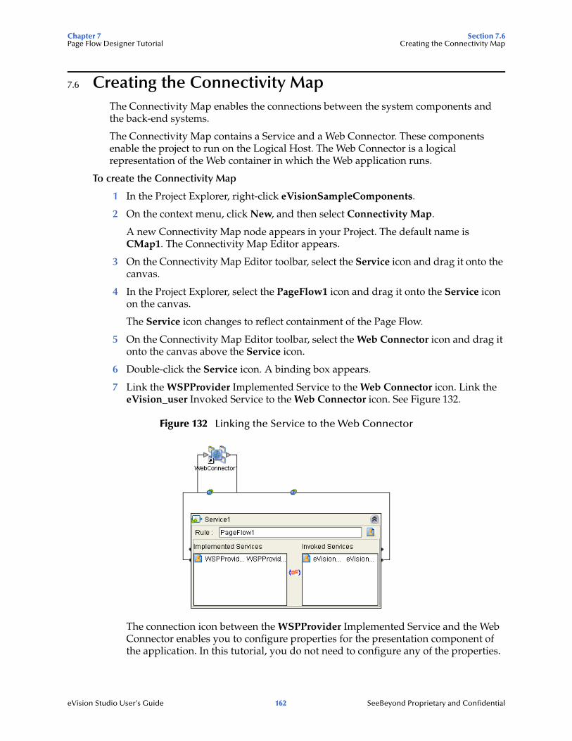
Chapter 7 Section 7.6Page Flow Designer Tutorial Creating the Connectivity Map
eVision Studio User’s Guide 162 SeeBeyond Proprietary and Confidential
7.6 Creating the Connectivity MapThe Connectivity Map enables the connections between the system components and the back-end systems.
The Connectivity Map contains a Service and a Web Connector. These components enable the project to run on the Logical Host. The Web Connector is a logical representation of the Web container in which the Web application runs.
To create the Connectivity Map
1 In the Project Explorer, right-click eVisionSampleComponents.
2 On the context menu, click New, and then select Connectivity Map.
A new Connectivity Map node appears in your Project. The default name is CMap1. The Connectivity Map Editor appears.
3 On the Connectivity Map Editor toolbar, select the Service icon and drag it onto the canvas.
4 In the Project Explorer, select the PageFlow1 icon and drag it onto the Service icon on the canvas.
The Service icon changes to reflect containment of the Page Flow.
5 On the Connectivity Map Editor toolbar, select the Web Connector icon and drag it onto the canvas above the Service icon.
6 Double-click the Service icon. A binding box appears.
7 Link the WSPProvider Implemented Service to the Web Connector icon. Link the eVision_user Invoked Service to the Web Connector icon. See Figure 132.
Figure 132 Linking the Service to the Web Connector
The connection icon between the WSPProvider Implemented Service and the Web Connector enables you to configure properties for the presentation component of the application. In this tutorial, you do not need to configure any of the properties.

Chapter 7 Section 7.7Page Flow Designer Tutorial Creating the Environment
eVision Studio User’s Guide 163 SeeBeyond Proprietary and Confidential
8 Minimize the binding box. The connectors appear crossed. This behavior is normal. See Figure 133.
Figure 133 Crossed Appearance of Connectors
7.7 Creating the EnvironmentIn this procedure, you create the run-time environment for the Web application. The environment consists of:
Logical Host (serves as the run-time platform)
SeeBeyond Integration Server (provides run-time services for the application)
eVision External System (represents where the presentation component of the application will execute)
To create the Environment
1 On the View menu, click Environment Explorer.
2 Right-click the Repository. On the context menu, select New Environment.
The default name of the Environment is Environmentn, where n is the next sequential default Environment number. You can accept the default name.
3 Right-click the Environment. On the context menu, click New, and then select New Logical Host.
The default name of the Logical Host is LogicalHost1. You can accept the default name.
4 Right-click the Logical Host. On the context menu, select New SeeBeyond Integration Server.
The default name of the Integration Server is IntegrationSvr1. You can accept the default name.
5 Right-click the Environment. On the context menu, click New, and then select New eVision External System. The Please input the name dialog box appears.
6 Type eVisionExtSys and click OK.
7 On the File menu, click Save All.
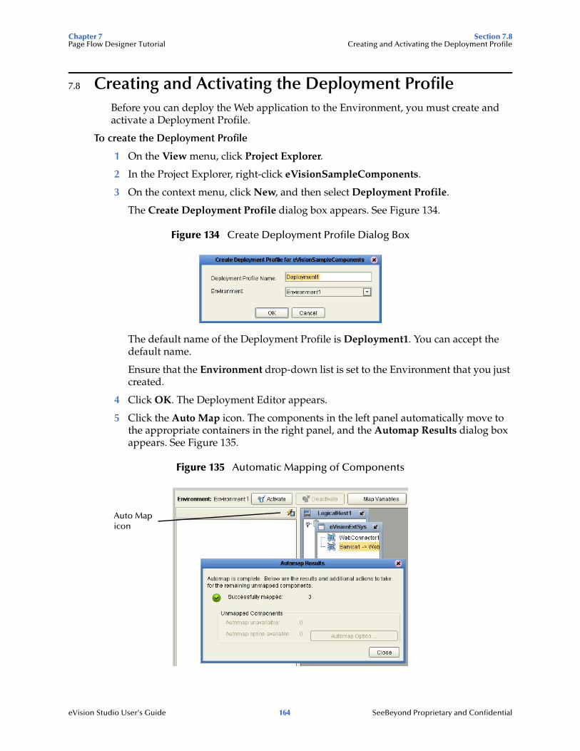
Chapter 7 Section 7.8Page Flow Designer Tutorial Creating and Activating the Deployment Profile
eVision Studio User’s Guide 164 SeeBeyond Proprietary and Confidential
7.8 Creating and Activating the Deployment ProfileBefore you can deploy the Web application to the Environment, you must create and activate a Deployment Profile.
To create the Deployment Profile
1 On the View menu, click Project Explorer.
2 In the Project Explorer, right-click eVisionSampleComponents.
3 On the context menu, click New, and then select Deployment Profile.
The Create Deployment Profile dialog box appears. See Figure 134.
Figure 134 Create Deployment Profile Dialog Box
The default name of the Deployment Profile is Deployment1. You can accept the default name.
Ensure that the Environment drop-down list is set to the Environment that you just created.
4 Click OK. The Deployment Editor appears.
5 Click the Auto Map icon. The components in the left panel automatically move to the appropriate containers in the right panel, and the Automap Results dialog box appears. See Figure 135.
Figure 135 Automatic Mapping of Components
Auto Map icon

Chapter 7 Section 7.8Page Flow Designer Tutorial Creating and Activating the Deployment Profile
eVision Studio User’s Guide 165 SeeBeyond Proprietary and Confidential
6 Click Close.
To activate the Deployment Profile
1 Click Activate. After a while, the Activate dialog box appears. See Figure 136.
Figure 136 Activate Dialog Box
2 Click No.
You click No because the Logical Host is not yet running. If you click Yes, the operation will fail. You will start the Logical Host in the next procedure.
If a project is deployed and you modify it and then re-deploy it, you can click Yes (if the Logical Host is already running).
3 The eVision Application URL dialog box displays the URL for the Web application that you just created. You will need to enter the URL in the address field of your browser to access the Web application. Note that the Application URL dialog box allows you to copy and paste the URL. See Figure 137.
Figure 137 eVision Application URL Dialog Box
4 Click OK.

Chapter 7 Section 7.9Page Flow Designer Tutorial Running and Testing the Application
eVision Studio User’s Guide 166 SeeBeyond Proprietary and Confidential
7.9 Running and Testing the ApplicationNow that you have activated the Deployment Profile, you can start the Logical Host and access the Web application in your browser.
7.9.1 Starting the Logical HostIf you do not have a Logical Host installed, follow the instructions in the SeeBeyond ICAN Suite Installation Guide to install one.
The Logical Host bootstrap process executes the eVisionSampleComponents Project. The bootstrap process will pick up the Deployment Profile the first time it runs; after that, you select Reactivate and click Yes to apply the most recent changes to the Logical Host.
To start the Logical Host, you run a bootstrap script. The syntax is:
bootstrap argument1 ... argumentN
Some of the arguments are required, and other arguments are optional. Table 19 describes the required arguments.
The following procedure assumes that the Logical Host is installed on a Windows system.
To start the Logical Host
1 Open a command prompt.
2 Navigate to the ICAN-root\logicalhost\bootstrap\bin directory.
3 Run the bootstrap script with the required arguments. For example:
bootstrap -e Environment1 -l LogicalHost1 -r http://frodo.acme.com:12000/MyRepository -i Administrator -p STC
4 Wait until a message appears indicating that the Logical Host is ready.
Table 19 Logical Host Bootstrap Required Arguments
Argument Description
-e environment name
The name of the Environment where the Logical Host is deployed.
-l logicalhost name
The name of the Logical Host.
-r repository URL The root URL of the Repository containing the Logical Host data.
-i username The user name for accessing the Repository.
-p password The password for accessing the Repository.

Chapter 7 Section 7.9Page Flow Designer Tutorial Running and Testing the Application
eVision Studio User’s Guide 167 SeeBeyond Proprietary and Confidential
7.9.2 Accessing the Web ApplicationYou can now access the Web application in your browser.
To access the Web application
1 Ensure that the Repository is running.
2 Start your Web browser.
3 Enter the URL that appeared in the eVision Application URL dialog box.
The first page should look like the example in Figure 138.
Figure 138 Sample Web Application Startup Page
Enter an employee name and an employee number less than or equal to 5000, and then click RequestVacation. The vacation form prompts you to enter the desired number of days and your manager’s e-mail address.
On the first page, you can try entering an employee number greater than 5000. A page with an error message prompts you to try again.

Chapter 7 Section 7.10Page Flow Designer Tutorial Importing the Working Sample Project
eVision Studio User’s Guide 168 SeeBeyond Proprietary and Confidential
7.10 Importing the Working Sample ProjectWhen you are done with the tutorial, you can examine the sample reference Project in the eVisionTutorial_sample.zip file.
The Project is called eVisionTutorial. The Project contains two Page Flows. Each Page Flow has a corresponding Connectivity Map. Therefore, the Project enables you to deploy two Web applications. See Table 20.
To deploy either application, you must import the Project, create an Environment, create and activate a Deployment Profile, and start a Logical Host.
When you create a Deployment Profile, the components for both Page Flows appear in the left panel. You can do one of the following:
Deploy the components for the pf eVision Tutorial Page Flow
Deploy the components for the pfTutorial2 Page Flow
Deploy the components for both Page Flows
If you deploy the components for both Page Flows, two versions of the eVision Application URL dialog box will appear.
The application URL for the pf eVision Tutorial Page Flow will end with testPF.
You can access the applications in your browser, and work through the finished applications from a user’s perspective. You can also modify the Project to experiment with various features.
Table 20 Page Flows and Connectivity Maps in eVisionTutorial Project
Page Flow Connectivity Map Description
pf eVision Tutorial cm eVision Tutorial This application is a completed version of the application that you created in this chapter.
pfTutorial2 pfTutorialcmap This application is a more complex version of the application that you created in this chapter. In addition to requesting vacation time, employees can submit data for their timecard.
eVision Studio User’s Guide 169 SeeBeyond Proprietary and Confidential
Chapter 8
Creating Charts
This chapter describes how to use the Chart GUI component. This component is available from the Form Objects palette in the Page Layout Designer.
What’s in This Chapter
“Charts Overview” on page 169
“Adding a Chart to a Page Layout” on page 169
“Mapping Data into the Chart” on page 179
8.1 Charts OvervieweVision provides a variety of predefined chart types, including area charts, bar charts, line charts, and pie charts.
The process of creating a chart is divided into two phases:
1 Adding the chart to a Page Layout in the Page Layout Designer
2 Mapping data into the chart in the Page Flow Designer
8.2 Adding a Chart to a Page LayoutThe Page Layout Designer allows you to add one or more charts to a Page Layout.
To add a chart to a Page Layout
1 From the Extension Objects palette, drag the Chart component onto the canvas.
An area chart with boilerplate information appears.
2 If you want to change the chart type, do the following in the Properties sheet:
A In the left column, click the type property.
B In the right column, select the chart type from the drop-down menu. “Chart Types” on page 170 describes the available chart types.
3 Specify the behavior of each data set. See “Data Sets” on page 177.
4 Set additional properties as needed. See “Additional Properties” on page 178.

Chapter 8 Section 8.2Creating Charts Adding a Chart to a Page Layout
eVision Studio User’s Guide 170 SeeBeyond Proprietary and Confidential
5 To preview the chart, click the Preview icon on the Page Layout Designer toolbar. This feature has the following limitations:
Because you have not mapped data into the chart, you will see only boilerplate information. The actual data will appear at runtime.
You cannot see the values of the xAxisLabel and yAxisLabel properties until runtime.
You cannot see the color specified by the bgColor property until runtime.
8.2.1 Chart TypesThis section describes the available chart types.
Area
An area chart fills in the portion of the chart between the category axis and the lines that connect the data points. eVision provides the following area chart types:
areaChart
stackedAreaChart
xyAreaChart
The following figures show an example of the areaChart type.
Figure 139 Source Data for areaChart Example
Figure 140 areaChart Example

Chapter 8 Section 8.2Creating Charts Adding a Chart to a Page Layout
eVision Studio User’s Guide 171 SeeBeyond Proprietary and Confidential
The xyAreaChart type displays (x,y) pairs of data. Rather than presenting a category axis and a value axis, this chart type presents two value axes.
Bar
A bar chart displays the data points as vertical rectangles. eVision provides the following bar chart types:
barChart
barChart3D
stackedBarChart
stackedBarChart3D
The following figures show an example of the barChart type.
Figure 141 Source Data for barChart Example
Figure 142 barChart Example
The barChart3D and stackedBarChart3D types provide a 3-D visual effect.
The stackedBarChart and stackedBarChart3D types use a single bar to display the values for each category.

Chapter 8 Section 8.2Creating Charts Adding a Chart to a Page Layout
eVision Studio User’s Guide 172 SeeBeyond Proprietary and Confidential
Line
A line chart connects the data points with lines. eVision provides the following line chart types:
lineChart
xyLineChart
The following figures show an example of the lineChart type.
Figure 143 Source Data for lineChart Example
Figure 144 lineChart Example
The xyLineChart type displays (x,y) pairs of data. Rather than presenting a category axis and a value axis, this chart type presents two value axes.

Chapter 8 Section 8.2Creating Charts Adding a Chart to a Page Layout
eVision Studio User’s Guide 173 SeeBeyond Proprietary and Confidential
Pie
A pie chart displays the data as a circle that has been divided into two or more wedge-shaped segments. eVision provides the following pie chart types:
pieChart
pieChart3D
The following figures show an example of the pieChart type. In the chart, each segment is labeled with the raw number and the percentage.
Figure 145 Source Data for pieChart Example
Figure 146 pieChart Example
The pieChart3D type provides a 3-D visual effect.

Chapter 8 Section 8.2Creating Charts Adding a Chart to a Page Layout
eVision Studio User’s Guide 174 SeeBeyond Proprietary and Confidential
Scatter Plot
A scatter plot chart illustrates the correlation between (x,y) pairs of data. Rather than presenting a category axis and a value axis, this chart type presents two value axes. Each data point is represented by a dot. eVision provides the following scatter plot type:
scatterPlotChart
The following figures show an example of the scatterPlotChart type. In this example, the data has a high negative correlation.
Figure 147 Source Data for scatterPlotChart Example
Figure 148 scatterPlotChart Example
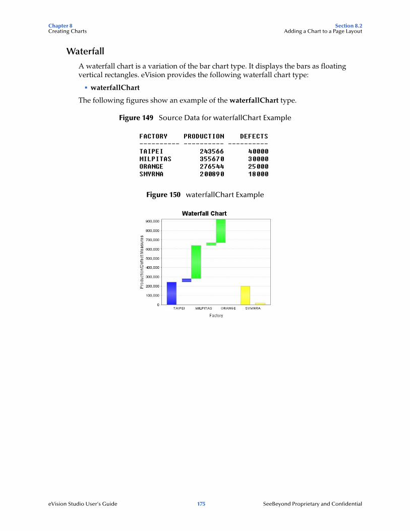
Chapter 8 Section 8.2Creating Charts Adding a Chart to a Page Layout
eVision Studio User’s Guide 175 SeeBeyond Proprietary and Confidential
Waterfall
A waterfall chart is a variation of the bar chart type. It displays the bars as floating vertical rectangles. eVision provides the following waterfall chart type:
waterfallChart
The following figures show an example of the waterfallChart type.
Figure 149 Source Data for waterfallChart Example
Figure 150 waterfallChart Example

Chapter 8 Section 8.2Creating Charts Adding a Chart to a Page Layout
eVision Studio User’s Guide 176 SeeBeyond Proprietary and Confidential
XY Step Area
An xy step area chart illustrates the correlation between (x,y) pairs of data. Rather than presenting a category axis and a value axis, this chart type presents two value axes. Each data point is represented by a vertical rectangle. The rectangles are joined in a way that makes them resemble a series of steps. eVision provides the following xy step area chart type:
xyStepAreaChart
The following figures show an example of the xyStepAreaChart type.
Figure 151 Source Data for xyStepAreaChart Example
Figure 152 xyStepAreaChart Example

Chapter 8 Section 8.2Creating Charts Adding a Chart to a Page Layout
eVision Studio User’s Guide 177 SeeBeyond Proprietary and Confidential
8.2.2 Data SetsA data set is a group of related data points. Each chart has one or more data sets.
The datasets property enables you to specify the characteristics of each data set. When you click the right column, the Edit Datasets dialog box appears. See Figure 153.
Figure 153 Edit Datasets Dialog Box
By default, the dialog box contains one data set.
For the chart types that are based on categories, you typically need to specify only one data set. For the chart types that are based on xy series, you may need to specify more than one data set. Table 21 lists the number of data sets for each chart type.
Table 21 Chart Types and Number of Data Sets
Chart Type Based On Number of Data Sets
areaChart Categories one
stackedAreaChart Categories one
xyAreaChart XY Series one or more
barChart Categories one
barChart3D Categories one
stackedBarChart Categories one
stackedBarChart3D Categories one
lineChart Categories one
xyLineChart XY Series one or more
pieChart Categories one
pieChart3D Categories one
scatterPlotChart XY Series one or more

Chapter 8 Section 8.2Creating Charts Adding a Chart to a Page Layout
eVision Studio User’s Guide 178 SeeBeyond Proprietary and Confidential
You will map data into the data set elements in the Page Flow Designer. See “Mapping Data into the Chart” on page 179.
Guidelines for Category Series Charts
The Number of X data column specifies the number of input sources to be used for the categories. For example, if you were creating the bar chart in Figure 142 on page 171, you would set this column to 1.
The Number of Y data column specifies the number of values for each category. For example, if you were creating the bar chart in Figure 142 on page 171, you would set this column to 2.
If you are creating a pie chart, then you must set the Number of Y data column to 1.
The Y Labels column enables you to specify the names in the chart legend. Separate the values with a comma (as in list price,sale price).
Guidelines for XY Series Charts
The Number of X data column specifies the number of input sources to be used for the x portion of the (x,y) pairs. For example, if you were creating the scatter plot chart in Figure 148 on page 174, you would set this column to 1.
The Number of Y data column specifies the number of input sources to be used for the y portion of the (x,y) pairs. For example, if you were creating the scatter plot chart in Figure 148 on page 174, you would set this column to 1.
The Y Labels column enables you to specify the names in the chart legend (as inPrice,Units Sold).
If the number of (x,y) pairs in each series is different, you must specify more than one data set.
8.2.3 Additional PropertiesAs with all of the eVision Studio GUI components, be sure to change the default value of the lname property to a more descriptive value.
The bgColor property indicates the color that appears in the background of the chart. The default color is white.
You can resize a chart using the mouse, or by changing values of the height and width properties.
The legend property indicates the location of the chart legend: north, east, south, or west. You can also remove the chart legend.
waterfallChart Categories one
xyStepAreaChart XY Series one or more
Table 21 Chart Types and Number of Data Sets
Chart Type Based On Number of Data Sets

Chapter 8 Section 8.3Creating Charts Mapping Data into the Chart
eVision Studio User’s Guide 179 SeeBeyond Proprietary and Confidential
The orientation property indicates whether the chart orientation is vertical or horizontal. The default setting is vertical.
Note: The pie chart types do not use the orientation property.
The title property enables you to add a title to the top of the chart. In addition, the value appears as a tooltip.
The xAxisLabel property enables you to specify a label for the category axis.
The yAxisLabel property enables you to specify a label for the value axis.
8.3 Mapping Data into the ChartAfter adding the chart to a Page Layout, you specify what data will appear in the chart. You perform this step in the Page Flow Designer.
The example in this section maps data from an Oracle database into the chart. Figure 154 shows the Page Flow.
Figure 154 Page Flow for Mapping Example
The mapping occurs in the inline business rule between the SelectAll operation of the Oracle OTD and the show operation of the Page Layout. Figure 155 shows the Business Rule Designer view of the inline business rule.
Figure 155 Inline Business Rule Mapping
inline business rule

Chapter 8 Section 8.3Creating Charts Mapping Data into the Chart
eVision Studio User’s Guide 180 SeeBeyond Proprietary and Confidential
The Output pane (on the left) represents the output from the SelectAll operation of the Oracle OTD. The OTD was created for a table called PRODUCTS that contains the following columns: PRODUCT_ID, PRODUCT_NAME, LIST_PRICE, and SALE_PRICE.
The Input pane (on the right) represents the input to the Page Layout. Each chart in the Page Layout is identified by its lname property. Figure 155 shows one chart named barChart.
The data set in each chart is identified by datasetn. The numeric portion starts from 0.
The x and y nodes under each data set correspond to the values that you entered in the Edit Datasets dialog box. The numeric portion starts from 0. For example, if you entered 2 in the Number of X data column and 4 in the Number of Y data column, the following nodes would appear:
x0
x1
y0
y1
y2
y3
In the example, the PRODUCT_NAME column represents the categories that will appear in the bar chart. Therefore, this column is mapped to the x0 node.
The LIST_PRICE and SALE_PRICE columns represent the values that will appear for each category. Therefore, these columns are mapped to the y0 and y1 nodes, respectively.
Figure 142 on page 171 shows how the chart appears when the Project is activated.

eVision Studio User’s Guide 181 SeeBeyond Proprietary and Confidential
Chapter 9
Authentication and Error Handling
This chapter describes how to add authentication to eVision Web applications, as well as how to return preconfigured pages for certain errors.
What’s in This Chapter
“Authentication and Error Handling Overview” on page 181
“Creating Authentication and Error-Handling Pages” on page 182
“Configuring the Connectivity Map” on page 183
“Specifying Users and Roles” on page 184
9.1 Authentication and Error Handling OverviewYou have for three authentication options for an eVision Web application:
No authentication.
Using the default ICAN Suite authentication.
Using the preconfigured authentication pages that are provided with eVision. This option is the most powerful.
Table 22 describes the preconfigured authentication pages.
Table 22 Preconfigued Authentication Pages
Authentication Page Description Required?
Login Page This page allows the user to enter login information. yes
Login Error This page is returned if the user enters an invalid username and/or password.
yes
Access Denied Error This page is returned if the user is not allowed to see the requested eVision page. Access Denied Error corresponds to the HTTP response codes 401 and 403. These response codes are two variations of the same error.
no

Chapter 9 Section 9.2Authentication and Error Handling Creating Authentication and Error-Handling Pages
eVision Studio User’s Guide 182 SeeBeyond Proprietary and Confidential
You can also return preconfigured error-handling pages to the user when a requested page cannot be found or when a more serious internal error has occurred. You can create these pages regardless of which authentication option you are using.
Table 23 describes the preconfigured error-handling pages that are provided with eVision.
Table 23 Preconfigured Error-Handling Pages
9.2 Creating Authentication and Error-Handling PagesThis section describes how to add a preconfigured authentication page or a preconfigured error-handling page to your Project. Perform this procedure for each page that you want to create.
To create an authentication or error-handling page
1 In the Project Explorer of Enterprise Designer, right-click the Project.
2 On the context menu, click New, and then select Page Layout.
Step 1 of the Page Layout Wizard appears.
3 In the Page Layout Name field, type a name for the Page Layout (for example, pgLoginError).
4 Click Next.
Step 2 of the Page Layout Wizard appears.
5 Select the authentication or error-handling page that you want to create.
6 Click Finish.
The Page Layout Designer appears with the page that you chose.
7 Because the page is preconfigured, you do not need make any changes in the Page Layout Designer. However, you might want to add a background or modify the title. You can perform these tasks in the Properties window.
Authentication Page Description
No Such Resource This page is returned if the requested eVision page cannot be found. No Such Resource corresponds to the HTTP response code 404.
Internal Server Error This page is returned to the user if there is a serious problem with the business process (for example, the business process is corrupt or the session was lost). Internal Server Error corresponds to the HTTP response code 500.
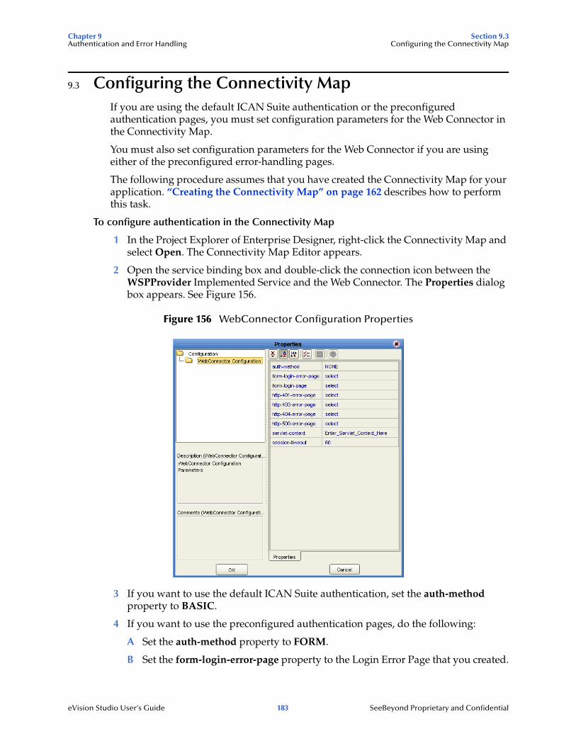
Chapter 9 Section 9.3Authentication and Error Handling Configuring the Connectivity Map
eVision Studio User’s Guide 183 SeeBeyond Proprietary and Confidential
9.3 Configuring the Connectivity MapIf you are using the default ICAN Suite authentication or the preconfigured authentication pages, you must set configuration parameters for the Web Connector in the Connectivity Map.
You must also set configuration parameters for the Web Connector if you are using either of the preconfigured error-handling pages.
The following procedure assumes that you have created the Connectivity Map for your application. “Creating the Connectivity Map” on page 162 describes how to perform this task.
To configure authentication in the Connectivity Map
1 In the Project Explorer of Enterprise Designer, right-click the Connectivity Map and select Open. The Connectivity Map Editor appears.
2 Open the service binding box and double-click the connection icon between the WSPProvider Implemented Service and the Web Connector. The Properties dialog box appears. See Figure 156.
Figure 156 WebConnector Configuration Properties
3 If you want to use the default ICAN Suite authentication, set the auth-method property to BASIC.
4 If you want to use the preconfigured authentication pages, do the following:
A Set the auth-method property to FORM.
B Set the form-login-error-page property to the Login Error Page that you created.

Chapter 9 Section 9.4Authentication and Error Handling Specifying Users and Roles
eVision Studio User’s Guide 184 SeeBeyond Proprietary and Confidential
C Set the form-login-page property to the Login Page that you created.
D If you created an Access Denied Error Page, set the http-401-error-page and http-403-error-page properties to the Access Denied Error Page.
Note: The Properties dialog box enables you to clear the values of the page properties.
5 If you created a No Such Resource Page, set the http-404-error-page property to the No Such Resource Page.
6 If you created an Internal Server Error Page, set the http-500-error-page property to the Internal Server Error Page.
7 Click OK.
9.4 Specifying Users and RolesThe final step of implementing the default ICAN Suite authentication or the preconfigured authentication pages is to specify which users and roles can access the application.
This step involves adding users and roles to the Environment and modifying the eVision External System to indicate which roles are authorized.
The following procedures assume that you have created an Environment for your application. The Environment must include an eVision External System. For more information, see “Creating the Environment” on page 163.
To add users and roles to the Environment
The “ICAN Security Features” chapter in the eGate Integrator System Administration Guide contains detailed information about how to add users and roles to an Environment. The following procedure is a condensed version of this information.
1 In the Environment Explorer of Enterprise Designer, right-click the Environment and select User Management. The User Management dialog box appears.
2 Click Add.
3 In the User field, enter a name for the user.
4 In the Password field, enter a password for the user.
5 In the Confirm Password field, enter the password again.
6 Click Add Role.
7 If you want to create a new role that can be assigned, do the following:
A Click Create Role.
B In the Role field, type the name of the role.
C Click OK.
8 Select the desired role(s) and click OK.
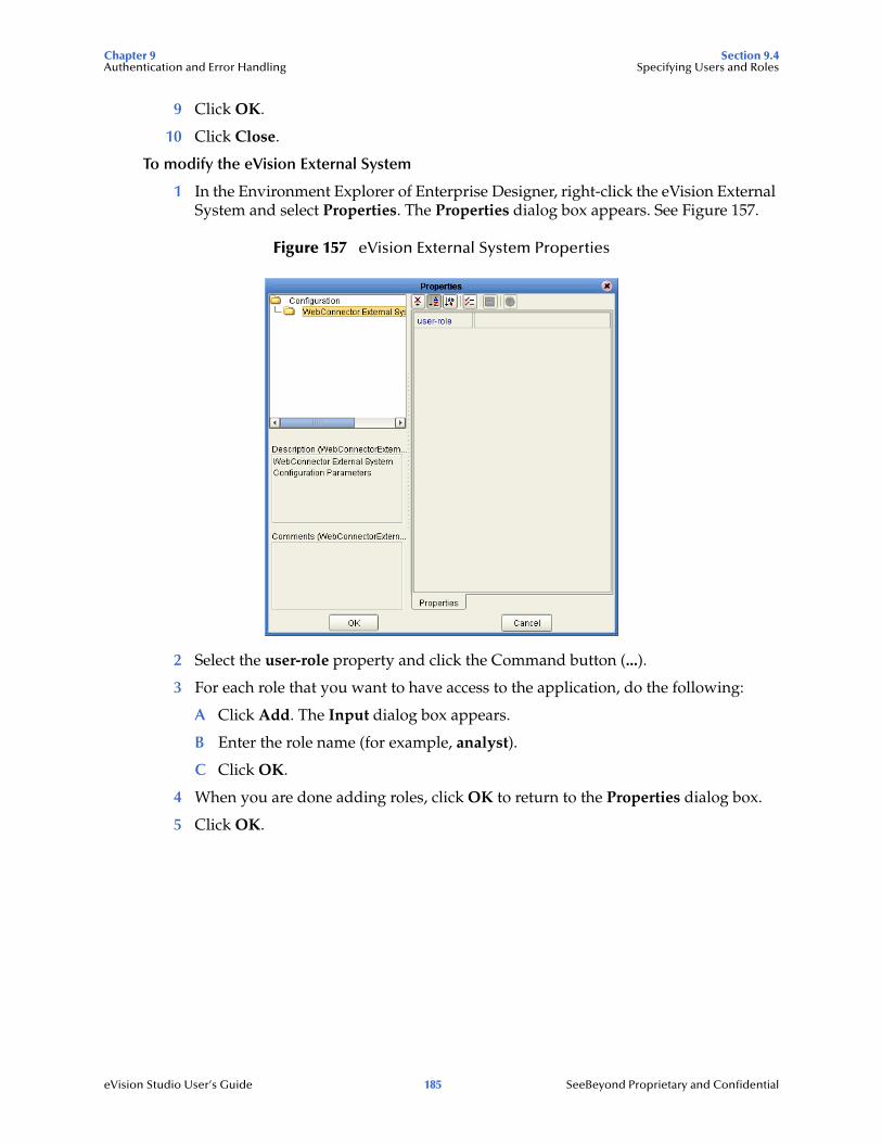
Chapter 9 Section 9.4Authentication and Error Handling Specifying Users and Roles
eVision Studio User’s Guide 185 SeeBeyond Proprietary and Confidential
9 Click OK.
10 Click Close.
To modify the eVision External System
1 In the Environment Explorer of Enterprise Designer, right-click the eVision External System and select Properties. The Properties dialog box appears. See Figure 157.
Figure 157 eVision External System Properties
2 Select the user-role property and click the Command button (...).
3 For each role that you want to have access to the application, do the following:
A Click Add. The Input dialog box appears.
B Enter the role name (for example, analyst).
C Click OK.
4 When you are done adding roles, click OK to return to the Properties dialog box.
5 Click OK.

eVision Studio User’s Guide 186 SeeBeyond Proprietary and Confidential
Appendix A
Method Palette
This appendix describes each method that appears in the Method Palette of the Business Rule Designer.
What’s in This Appendix
Operators on page 186String on page 189Number on page 192Boolean on page 194Nodes on page 195Datetime on page 197Conversion on page 199
A.1 OperatorsOperators are the methods that allow you to manipulate data with standard mathematical operators.
Figure 158 Method Palette: Operator Tab

Appendix A Section A.1Method Palette Operators
eVision Studio User’s Guide 187 SeeBeyond Proprietary and Confidential
Table 24 Operator Methods
Symbol Name Function
addition Adds the value of number1 to the value of number2, returns the sum.
div Divides the value of number1 by the value of number2, returns the quotient.
greater or equal Returns Boolean true if number1 is greater than or equal to number2; otherwise, returns Boolean false.
lesser or equal Returns Boolean true if number1 is less than or equal to number2; otherwise, returns Boolean false.
mod Used to divide two numbers and return only the remainder.
negative Converts the input number to negative. Result is a negative number having the same absolute value as the input number.
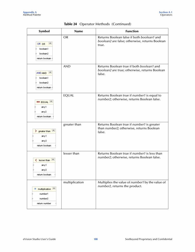
Appendix A Section A.1Method Palette Operators
eVision Studio User’s Guide 188 SeeBeyond Proprietary and Confidential
OR Returns Boolean false if both boolean1 and boolean2 are false; otherwise, returns Boolean true.
AND Returns Boolean true if both boolean1 and boolean2 are true; otherwise, returns Boolean false.
EQUAL Returns Boolean true if number1 is equal to number2; otherwise, returns Boolean false.
greater than Returns Boolean true if number1 is greater than number2; otherwise, returns Boolean false.
lesser than Returns Boolean true if number1 is less than number2; otherwise, returns Boolean false.
multiplication Multiplies the value of number1 by the value of number2, returns the product.
Table 24 Operator Methods (Continued)
Symbol Name Function

Appendix A Section A.1Method Palette String
eVision Studio User’s Guide 189 SeeBeyond Proprietary and Confidential
A.1 StringThe String methods allow you to manipulate string data.
Figure 159 Method Palette: String Tab
not equal Returns Boolean true if number1 is not equal to number2; otherwise, returns Boolean false.
subtraction Subtracts the numerical value of number2 from the numerical value of number1, returns the difference.
Table 24 Operator Methods (Continued)
Symbol Name Function

Appendix A Section A.1Method Palette String
eVision Studio User’s Guide 190 SeeBeyond Proprietary and Confidential
Table 25 String Methods
Symbol Name Function
bytes to text Decodes bytes into text using the specified encoding. If no encoding is specified, the platform's default encoding is used.
contains Returns true if the second string is contained within the first string, otherwise it returns false
copy to Allows you to type in the xpath expression for the destination of a copy operation. This is useful for entering xpath predicates. Note: This is for advanced users who are familiar with xpath and BPEL syntax.
starts with Returns true if the first string starts with the second string, otherwise it returns false
string length Returns the number of characters in a string
text to bytes Encodes the input text into a sequence of bytes using the specified encoding. If no encoding is specified, the platform's default encoding is used
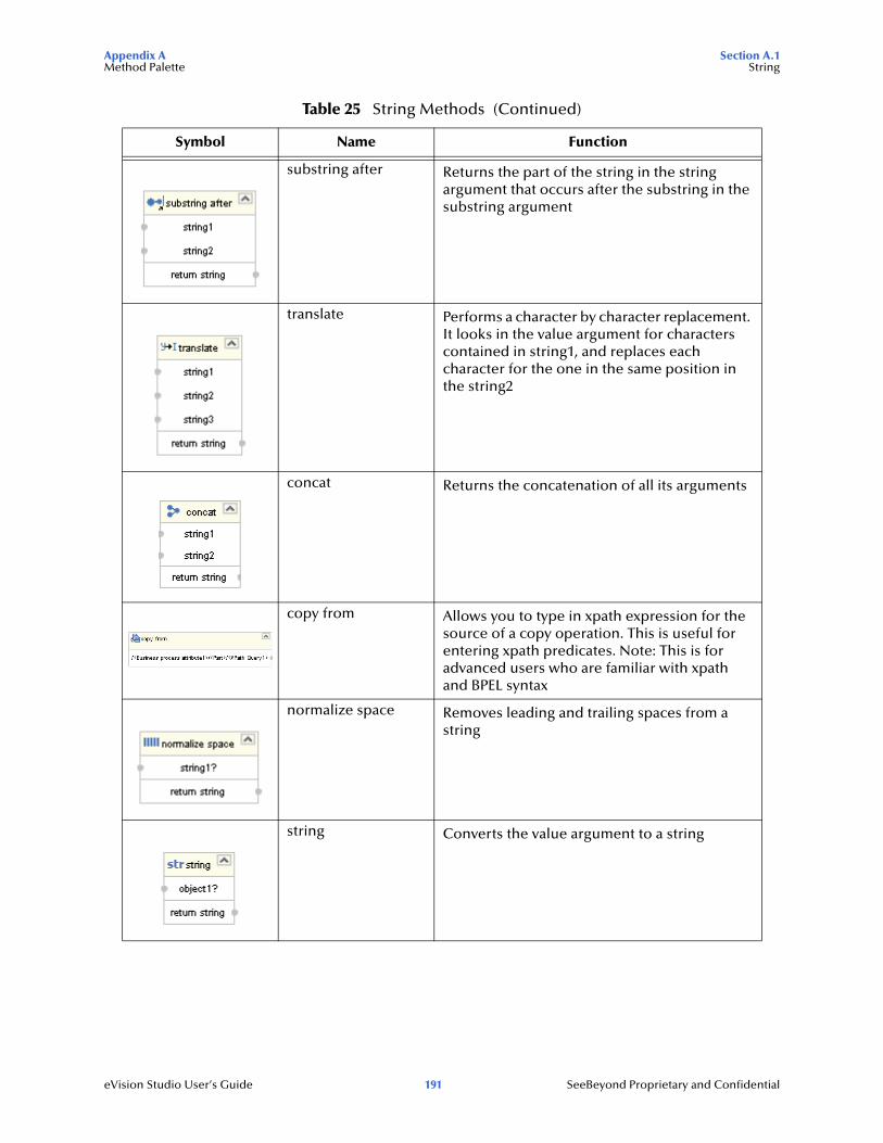
Appendix A Section A.1Method Palette String
eVision Studio User’s Guide 191 SeeBeyond Proprietary and Confidential
substring after Returns the part of the string in the string argument that occurs after the substring in the substring argument
translate Performs a character by character replacement. It looks in the value argument for characters contained in string1, and replaces each character for the one in the same position in the string2
concat Returns the concatenation of all its arguments
copy from Allows you to type in xpath expression for the source of a copy operation. This is useful for entering xpath predicates. Note: This is for advanced users who are familiar with xpath and BPEL syntax
normalize space Removes leading and trailing spaces from a string
string Converts the value argument to a string
Table 25 String Methods (Continued)
Symbol Name Function
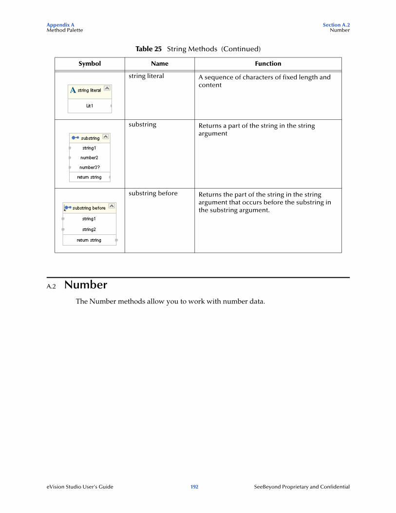
Appendix A Section A.2Method Palette Number
eVision Studio User’s Guide 192 SeeBeyond Proprietary and Confidential
A.2 NumberThe Number methods allow you to work with number data.
string literal A sequence of characters of fixed length and content
substring Returns a part of the string in the string argument
substring before Returns the part of the string in the string argument that occurs before the substring in the substring argument.
Table 25 String Methods (Continued)
Symbol Name Function

Appendix A Section A.2Method Palette Number
eVision Studio User’s Guide 193 SeeBeyond Proprietary and Confidential
Figure 160 Method Palette: Number Tab
Table 26 Number Methods
Symbol Name Function
ceiling Returns the smallest integer that is not less than the number argument
floor Returns the largest integer that is not greater than the number argument
number Converts the value argument to a number
number literal A literal number string of fixed length and content

Appendix A Section A.3Method Palette Boolean
eVision Studio User’s Guide 194 SeeBeyond Proprietary and Confidential
A.3 BooleanBoolean methods allow you to apply boolean logic to your data.
Figure 161 Method Palette: Boolean Tab
round Rounds the number argument to the nearest integer
sum Returns the total value of a set of numeric values in a node-set
Table 26 Number Methods (Continued)
Symbol Name Function

Appendix A Section A.4Method Palette Nodes
eVision Studio User’s Guide 195 SeeBeyond Proprietary and Confidential
A.4 NodesNode methods allow you to manipulate your data.
Table 27 Boolean Methods
Symbol Name Function
boolean Converts the value argument to Boolean and returns true or false.
true Returns true
false Returns false
lang Returns true if the language argument matches the language of the xsl:lang element, otherwise it returns false.
not Returns true if the condition argument is false, and false is the condition argument is true.
exists Checks to see if a value is present and returns a Boolean result.
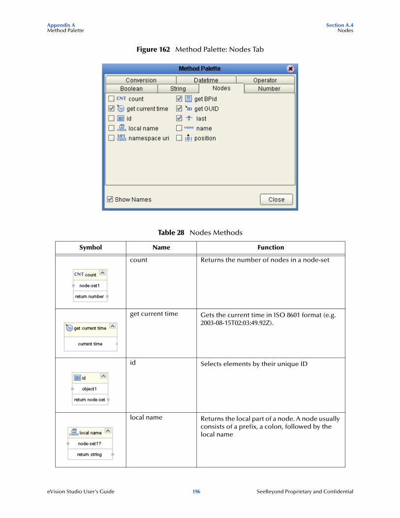
Appendix A Section A.4Method Palette Nodes
eVision Studio User’s Guide 196 SeeBeyond Proprietary and Confidential
Figure 162 Method Palette: Nodes Tab
Table 28 Nodes Methods
Symbol Name Function
count Returns the number of nodes in a node-set
get current time Gets the current time in ISO 8601 format (e.g. 2003-08-15T02:03:49.92Z).
id Selects elements by their unique ID
local name Returns the local part of a node. A node usually consists of a prefix, a colon, followed by the local name

Appendix A Section A.5Method Palette Datetime
eVision Studio User’s Guide 197 SeeBeyond Proprietary and Confidential
A.5 DatetimeDatetime methods allow you to manipulate date, time, and duration of data.
namespace uri Returns the namespace URI of a specified node
get BPid Gets the business process instance ID.
get GUID Gets a randomly generated globally unique ID.
last Returns the position number of the last node in the processed node list
name Returns the name of a node
position Returns the position in the node list of the node that is currently being processed
Table 28 Nodes Methods (Continued)
Symbol Name Function

Appendix A Section A.5Method Palette Datetime
eVision Studio User’s Guide 198 SeeBeyond Proprietary and Confidential
Figure 163 Method Palette: Datetime Tab
Table 29 Datetime Methods
Symbol Name Function
decrement datetime Dynamically decreases the date or time by a certain duration, such as days or hours.
increment datetime Dynamically increases the date or time by a certain duration, such as days or hours.
duration literal Allows you to set an actual date or time.
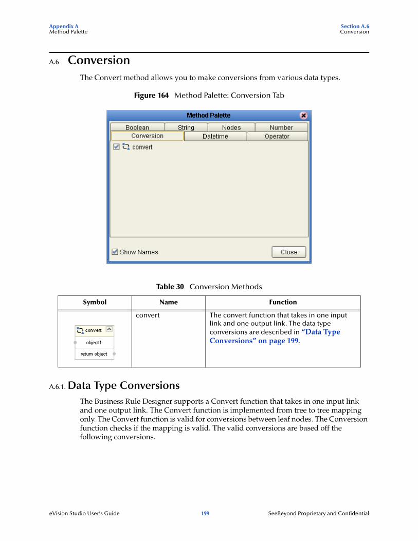
Appendix A Section A.6Method Palette Conversion
eVision Studio User’s Guide 199 SeeBeyond Proprietary and Confidential
A.6 ConversionThe Convert method allows you to make conversions from various data types.
Figure 164 Method Palette: Conversion Tab
A.6.1. Data Type ConversionsThe Business Rule Designer supports a Convert function that takes in one input link and one output link. The Convert function is implemented from tree to tree mapping only. The Convert function is valid for conversions between leaf nodes. The Conversion function checks if the mapping is valid. The valid conversions are based off the following conversions.
Table 30 Conversion Methods
Symbol Name Function
convert The convert function that takes in one input link and one output link. The data type conversions are described in “Data Type Conversions” on page 199.

Appendix A Section A.6Method Palette Conversion
eVision Studio User’s Guide 200 SeeBeyond Proprietary and Confidential
String
Boolean
Table 31 String
To From
Boolean custom
Float parse
Double parse
Decimal parse
Byte parse
Short parse
Int parse
Long parse
Duration parse
dateTime parse
time parse
date parse
gYearMonth parse
gYear parse
gMonthDay parse
gDay parse
gMonth parse
hexBinary textToByte
base64Binary textToByte
anyURI parse
QName parse
NOTATION parse
Table 32 Boolean
To From
String toString

Appendix A Section A.6Method Palette Conversion
eVision Studio User’s Guide 201 SeeBeyond Proprietary and Confidential
Float
Double
Decimal
Table 33 Float
To From
String toString
Boolean boolean
Double floatToDouble
Decimal floatToDecimal
Byte floatToByte
Short floatToShort
Int floatToInt
Long floatToLong
Table 34 Double
To From
String toString
Boolean boolean
Float doubleToFloat
Decimal doubleToDecimal
Byte doubleToByte
Short doubleToShort
Int doubleToInt
Long doubleToLong
Table 35 Decimal
To From
String toString
Boolean boolean
Float decimalToFloat
Double decimalToDouble
Byte decimalToByte

Appendix A Section A.6Method Palette Conversion
eVision Studio User’s Guide 202 SeeBeyond Proprietary and Confidential
Byte
Short
Short decimalToShort
Int decimalToInt
Long decimalToLong
Table 36 Byte
To From
String toString
Boolean boolean()
Float byteToFloat
Double byteToDouble
Decimal byteToDecimal
Short byteToShort
Int byteToInt
Long byteToLong
Table 37 Short
To From
String toString
Boolean boolean()
Float shortToFloat
Double shortToDouble
Decimal shortToDecimal
Byte shortToByte
Int shortToInt
Long shortToLong
Table 35 Decimal (Continued)
To From

Appendix A Section A.6Method Palette Conversion
eVision Studio User’s Guide 203 SeeBeyond Proprietary and Confidential
Int
Long
Duration
Table 38 Int
To From
String toString
Boolean boolean()
Float intToFloat
Double intToDouble
Decimal intToDecimal
Byte intToByte
Short intToShort
Long intToLong
Table 39 Long
To From
String toString
Boolean boolean()
Float longToFloat
Double longToDouble
Decimal longToDecimal
Byte longToByte
Short longToShort
Int longToInt
Table 40 Duration
To From
String toString
Boolean boolean

Appendix A Section A.6Method Palette Conversion
eVision Studio User’s Guide 204 SeeBeyond Proprietary and Confidential
dateTime
time
date
Table 41 dateTime
To From
String toString
Boolean boolean
time dateTimeToTime
date dateTimeToDate
gYearMonth dateTimeToGYearMonth
gYear dateTimeToGYear
gMonthDay dateTimeToGMonthDay
gDay dateTimeToGDay
gMonth dateTimeToGMonth
Table 42 time
To From
String toString
Boolean boolean
Table 43 date
To From
String toString
Boolean boolean
gYearMonth dateToGYearMonth
gYear dateToGYear
gMonthDay dateToGMonthDay
gDay dateToGDay
gMonth dateToGMonth

Appendix A Section A.6Method Palette Conversion
eVision Studio User’s Guide 205 SeeBeyond Proprietary and Confidential
gYearMonth
gYear
gMonthDay
gDay
Table 44 gYearMonth
To From
String toString
Boolean boolean
gYear gYearMonthToGYear
gMonth gYearMonthToGMonth
Table 45 gYear
To From
String toString
Boolean boolean
Table 46 gMonthDay
To From
String toString
Boolean boolean
gDay gMonthDayToGDay
gMonth gMonthDayToGMonth
Table 47 gDay
To From
String toString
Boolean boolean

Appendix A Section A.6Method Palette Conversion
eVision Studio User’s Guide 206 SeeBeyond Proprietary and Confidential
gMonth
hexBinary
base64Binary
anyURI
Table 48 gMonth
To From
String toString
Boolean boolean
Table 49 hexBinary
To From
String byteToText
Boolean boolean
base64Binary hexBinaryToBase64Binary
Table 50 base64Binary
To From
String byteToText
Boolean boolean
hexBinary base64BinaryToHexBinary
Table 51 anyURI
To From
String toString
Boolean boolean

Appendix A Section A.6Method Palette Conversion
eVision Studio User’s Guide 207 SeeBeyond Proprietary and Confidential
QName
NOTATION
Table 52 QName
To From
String toString
Boolean boolean
Table 53 NOTATION
To From
String toString
Boolean boolean

eVision Studio User’s Guide 208 SeeBeyond Proprietary and Confidential
Appendix B
Conversational State in eVision Studio Web Applications
This appendix describes the support for conversational state in eVision Studio Web applications.
What’s in This Appendix
“Overview” on page 208
“Example” on page 209
B.1 OverviewHTTP is a stateless protocol, which means that Web applications must use some type of mechanism to maintain conversational state with clients. For example, the application might store a cookie on the user’s computer.
In eVision Studio Web applications, Event Based Decision elements have the ability to maintain conversational state. When an Event Based Decision element is accessed in a Page Flow, the element keeps track of which Pages the user accesses. The user can leave a page and return to it as often as necessary.
This feature is particularly effective in promoting smooth page transitions when a user is moving from page to page in an unpredictable or non-sequential manner.

Appendix B Section B.2Conversational State in eVision Studio Web Applications Example
eVision Studio User’s Guide 209 SeeBeyond Proprietary and Confidential
B.2 ExampleThe following Page Flow will be used to illustrate conversational state in eVision Studio. Because of the size of the Page Flow, it is shown in two figures. The right boundary of Figure 165 continues to the left boundary of Figure 166. The letters A and B and the numbers 1 through 13 are used in the explanation that follows.
Figure 165 Page Flow Example - Part 1
Figure 166 Page Flow Example - Part 2
A
1 2 3
4 5 6
7B
8 9 10
11 12 13

Appendix B Section B.2Conversational State in eVision Studio Web Applications Example
eVision Studio User’s Guide 210 SeeBeyond Proprietary and Confidential
The Page Flow contains two Event Based Decision elements:
Event Based Decision A contains six pages (1 through 6).
Event Based Decision B contains six pages (8 through 13).
Page 7 is located between the Event Based Decisions.
Once a user enters Event Based Decision A and accesses the home page, Event Based Decision A becomes “active” for the remainder of the Page Flow. If the user jumps from page 1 to page 2 and then clicks the Back button, the state of page 1 is preserved. Similarly, the user can jump from page 1 to page 2 to page 3 to page 2 to page 1.
Event Based Decision A must be active before Event Based Decision B can become active.
In addition, the user must access page 7 before Event Based Decision B can become active. For example, the user can jump from page 1 to page 2 to page 3 to page 7 to page 8. The user cannot jump from page 1 directly to page 8.
Once a user enters Event Based Decision B and accesses either link, Event Based Decision B becomes active for the remainder of the Page Flow. As with Event Based Decision A, the user can click the Button button and the state of previous pages are preserved. For example, the following sequence is valid:
1 - 2 - 3 - 7 - 8 - 9 - 10 - 9 - 8 - 7 - 3 - 2 - 1 - 2 - 3 - 7 - 11 - 12 - 13
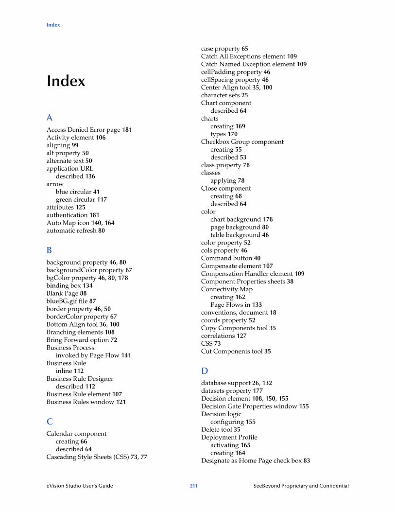
Index
eVision Studio User’s Guide 211 SeeBeyond Proprietary and Confidential
Index
AAccess Denied Error page 181Activity element 106aligning 99alt property 50alternate text 50application URL
described 136arrow
blue circular 41green circular 117
attributes 125authentication 181Auto Map icon 140, 164automatic refresh 80
Bbackground property 46, 80backgroundColor property 67bgColor property 46, 80, 178binding box 134Blank Page 88blueBG.gif file 87border property 46, 50borderColor property 67Bottom Align tool 36, 100Branching elements 108Bring Forward option 72Business Process
invoked by Page Flow 141Business Rule
inline 112Business Rule Designer
described 112Business Rule element 107Business Rules window 121
CCalendar component
creating 66described 64
Cascading Style Sheets (CSS) 73, 77
case property 65Catch All Exceptions element 109Catch Named Exception element 109cellPadding property 46cellSpacing property 46Center Align tool 35, 100character sets 25Chart component
described 64charts
creating 169types 170
Checkbox Group componentcreating 55described 53
class property 78classes
applying 78Close component
creating 68described 64
colorchart background 178page background 80table background 46
color property 52cols property 46Command button 40Compensate element 107Compensation Handler element 109Component Properties sheets 38Connectivity Map
creating 162Page Flows in 133
conventions, document 18coords property 52Copy Components tool 35correlations 127CSS 73Cut Components tool 35
Ddatabase support 26, 132datasets property 177Decision element 108, 150, 155Decision Gate Properties window 155Decision logic
configuring 155Delete tool 35Deployment Profile
activating 165creating 164
Designate as Home Page check box 83

Index
eVision Studio User’s Guide 212 SeeBeyond Proprietary and Confidential
document conventions 18documentation
uploading 29Drop-Down List component
creating multiple entries 57described 54making dynamic 57
dynamic tablesabout 47mapping data into 117pagination 48predicates 118sorting 48
EEdit CSS tool 36, 73eInsight 132, 141element class 78Empty element 107Enterprise Designer
updating with eVision modules 29Enterprise Manager
logging in 27, 86, 146EQUAL method 154Event Based Decision element 108, 208
configuring 114eVision External System 140eVision Studio
described 17installing 26operating systems 26overview 20
eVision Style Editor 74eVision.css file 73eVision.sar file 28eVision_user service 134eVision-default.css file 73eVisionDocs.sar file 29eVisionSampleComponents.zip file 147eVisionTutorial_sample.zip file 147, 168exception handling 109Extension Objects palette
accessing 37described 64
External SystemeVision 140
FfirstImg property 48Flow element 108fontColor property 45, 49fontSize property 45, 49
Form Objects paletteaccessing 37described 53
form property type 81frame property 46
GgalleryImg property 51, 69, 70GUI components
described 36placing on the canvas 91
Hheight property 50, 178Hidden component
creating 63described 53
Home pagedesignating 83
Horizontal Line componentcreating 52described 43
Horizontal Spacing tool 36href property 44, 52hSpace property 50HTML Objects palette
accessing 37described 43
Ii_seebeyondlogo.gif file 87IBM AIX
configuration changes 31IE category 39If component
creating 65described 64
Image Button componentcreating 59described 53mouse coordinates 122
Image componentcreating 50described 43
Image Map componentcreating 51described 43
imagesimporting 41
imageToolbar property 51, 69, 70
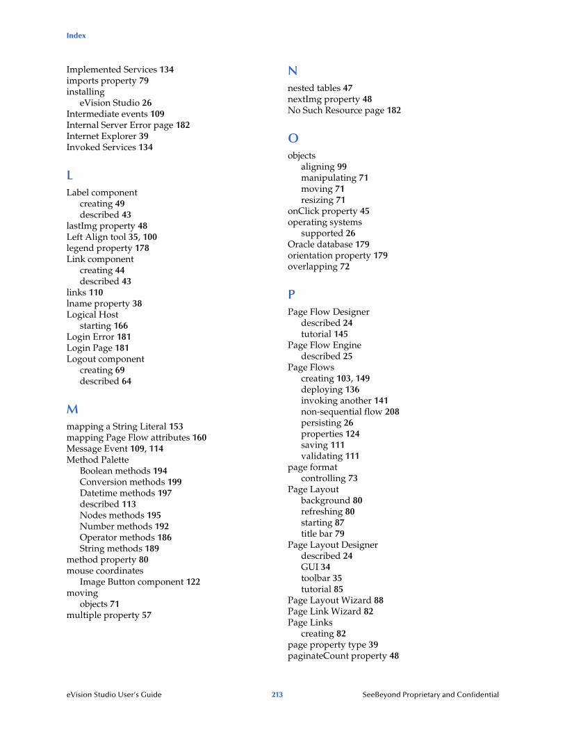
Index
eVision Studio User’s Guide 213 SeeBeyond Proprietary and Confidential
Implemented Services 134imports property 79installing
eVision Studio 26Intermediate events 109Internal Server Error page 182Internet Explorer 39Invoked Services 134
LLabel component
creating 49described 43
lastImg property 48Left Align tool 35, 100legend property 178Link component
creating 44described 43
links 110lname property 38Logical Host
starting 166Login Error 181Login Page 181Logout component
creating 69described 64
Mmapping a String Literal 153mapping Page Flow attributes 160Message Event 109, 114Method Palette
Boolean methods 194Conversion methods 199Datetime methods 197described 113Nodes methods 195Number methods 192Operator methods 186String methods 189
method property 80mouse coordinates
Image Button component 122moving
objects 71multiple property 57
Nnested tables 47nextImg property 48No Such Resource page 182
Oobjects
aligning 99manipulating 71moving 71resizing 71
onClick property 45operating systems
supported 26Oracle database 179orientation property 179overlapping 72
PPage Flow Designer
described 24tutorial 145
Page Flow Enginedescribed 25
Page Flowscreating 103, 149deploying 136invoking another 141non-sequential flow 208persisting 26properties 124saving 111validating 111
page formatcontrolling 73
Page Layoutbackground 80refreshing 80starting 87title bar 79
Page Layout Designerdescribed 24GUI 34toolbar 35tutorial 85
Page Layout Wizard 88Page Link Wizard 82Page Links
creating 82page property type 39paginateCount property 48

Index
eVision Studio User’s Guide 214 SeeBeyond Proprietary and Confidential
pagination 48parameters
Page Link 83passing into application URL 139
partners 127, 142Password component
creating 62described 53
Paste Components tool 35percentComplete property 67Persist State property 125, 133persistence
configuration summary 132databases supported 26
predicates 118Preview tool 36, 58, 100prevImg property 48ProductsManifest.xml file 28Progress Bar component
creating 67described 64
progressColor property 67properties
alt 50background 46, 80backgroundColor 67bgColor 46, 80, 178border 46, 50borderColor 67case 65cellPadding 46cellSpacing 46class 78color 52cols 46coords 52datasets 177defining 38firstImg 48fontColor 45, 49fontSize 45, 49frame 46galleryImg 51, 69, 70height 50, 178href 44, 52hSpace 50imageToolbar 51, 69, 70imports 79lastImg 48legend 178lname 38method 80multiple 57nextImg 48
onClick 45orientation 179paginateCount 48percentComplete 67prevImg 48progressColor 67readOnly 60, 61refresh 80refreshSecs 80rows 46rules 46sort 48sortType 49src 51, 68, 69style 77styleSheet 76summary 47tabIndex 57, 62target 44text 44, 49, 61title 45, 63, 79, 179type 169validationArgs 60, 66validationEmpty 60validationMsg 55, 56, 57, 60, 62, 66validationType 55, 56, 57, 60, 62value 58, 59, 60, 63, 65vSpace 50width 47, 50, 178xAxisLabel 179yAxisLabel 179z-index 72, 93
property categories 39property sheets 36property types 38
RRadio Group component
creating 56described 54
readOnly property 60, 61Receive element 106Redo tool 35refresh
automatic 80refresh property 80refreshSecs property 80repeating node 47, 117Reply element 107Reset Button component
creating 63described 54
Reset destination 121

Index
eVision Studio User’s Guide 215 SeeBeyond Proprietary and Confidential
resizingobjects 71
revert 75Right Align tool 35, 100roles
specifying 184rows property 46rules property 46
Ssample project
downloading 146importing 147
Save As feature 81Scope element 110Screenshots 19Select Image Map tool 51Select Link Area tool 51Send Backward option 72servlet context 137servlet-context property 137session-timeout property 135sort property 48sorting
dynamic tables 48sortType property 49src property 51, 68, 69SSL support 140state 208string literal method 153style editor 74style property 77style sheet
applying 76clearing 77customizing 73elements 74importing 76local styles 77
styleSheet property 76Submit Button component
creating 58, 99described 54
summary property 47Switch component
creating 65described 64
TtabIndex property 57, 62Table component
background color 46
background image 46border 46described 43dynamic 47nesting 47pagination 48sorting 48
Target Namespace property 125target property 44template.css file 73Terminate Process handler 109Text Area component
creating 61described 54
Text Box componentcreating 60described 54
text property 44, 49, 61theme 125Throw handler 109timeout 68, 69, 135Timer Event 109, 114title property 45, 63, 79, 179tooltip 45, 63, 179Top Align tool 35, 100tutorial
Page Flow Designer 145Page Layout Designer 85
type property 169
Uu002F 139Undo tool 35Update Center Wizard 29Upload component
creating 62described 53
URLeVision application 136, 165
user-role property 185users
specifying 184UTF-8 support 25
VvalidationArgs property 60, 66validationEmpty property 60validationMsg property 55, 56, 57, 60, 62, 66validationType property 55, 56, 57, 60, 62value property 58, 59, 60, 63, 65Version Control 101, 148Vertical Spacing tool 36

Index
eVision Studio User’s Guide 216 SeeBeyond Proprietary and Confidential
vSpace property 50
WWait element 107Web Connector 134, 162While element 110, 150width property 47, 50, 178window.open() method 45Worklist Viewer 133WSDL 131WSPProvider service 134
XxAxisLabel property 179
YyAxisLabel property 179
Zz-direction 72z-index property 72, 93